Embed Size (px)
Citation preview

By BILL HUSA, EAA 236620,1827 N. 192nd St., Seattle, WA 98133
With the nearly ridiculous pricesmost of us are forced to pay for air-craft engines, fuel and enginecomponents, it is only natural for theconsumer to be looking for alterna-tives. About two years ago ourcompany conducted a market sur-vey of this industry to see what thecurrent demands are and what fu-ture trends might evolve. Althoughwe were primarily looking at aircraftconfigurations, the survey did touchupon powerplant options.
The results were interesting inthat they pointed out a number ofunexpected values the aviationbuyer seems to hold dear. Althoughthere was a significant interest in thedevelopment of alternative power-plants for aircraft, the averageaircraft buyer or builder still pre-ferred the conservative Lycoming orContinental, even if he had to paythrough the nose to get it. This wasespecially interesting since most ofthose questioned seemed to con-sider both engines outdated, ineffi-cient, overpriced, and mechanicallypoor in design.
The key to the popularity of thoseengines today seems to be that ofperception, the feeling being thatsince the designs have been flyingfor more than four decades with rel-atively good performance and safety,that's what most want to stick with.Over the years a number of develop-ers have come out with promisingnew engines or engine configura-tions only to fail within a very shorttime, wondering why the aviationworld hasn't beat a path to theirdoors. The answer, of course, issimple - the aviation engine is not amousetrap.
Too much rides on the selectionof an engine, namely your life. Againthe idea of perception comes in. Anew engine or reduction drive is of-ten viewed as an item of interest orin some cases as an interesting odd-ity, but hardly what one would wantto install into his or her airplane, notuntil it's proven anyway. Only whenthe items have been installed into anairplane, have demonstrated safeand dependable operation and havebeen exposed to the market in a pro-
fessional and responsible way, onlythen will the aviation buyer considerthe new product a viable option.But, unfortunately, even all that isnot a guarantee.
The supplier or designer mustalso be able to demonstrate techni-cal and engineering know-how orthe credibility of the design is noth-ing more than meaningless armwaving; this is where I find quite alarge number of the reduction drivesofferd today fall short. They aredesigned and/or fabricated by indi-viduals who may be mechanicalcraftsmen, or may have a bit of tech-nical background and an impressivearray of machining tools, producinggear-trains that look to be works ofart, but on closer examination I'veoften found the advertised perfor-mance values questionable.
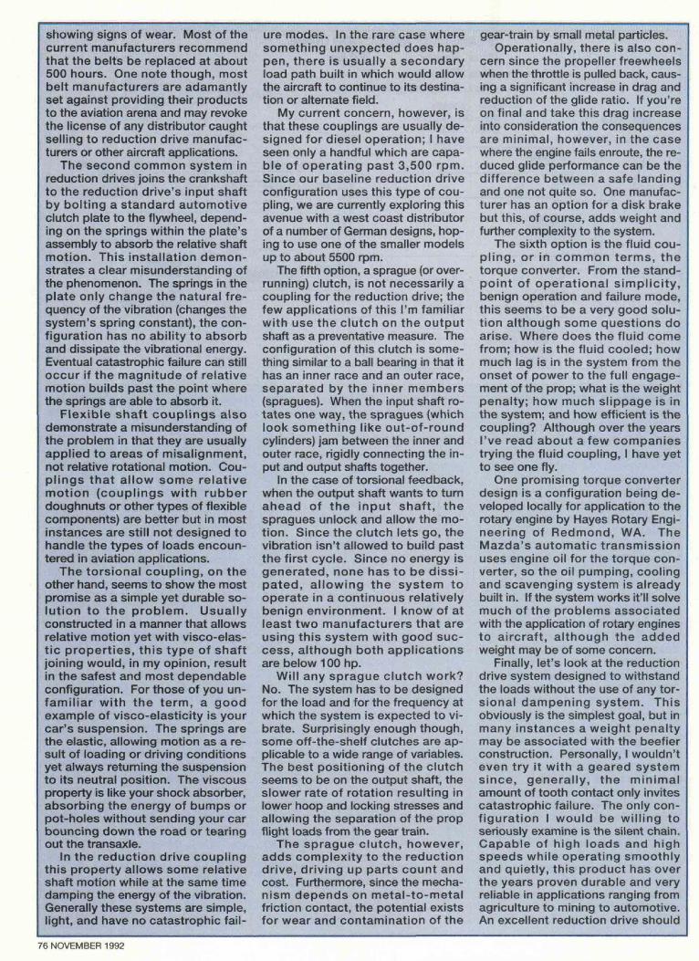
After looking at the market andnot finding anything suitable for ourpurposes (either due to our lack ofconfidence in the product or its in-capability to conform to ourapplication), we've decided to de-sign and manufacture a reductiondrive of our own (the layout of theprototype is shown in Figure 1). Thefirst box should be assembled andready for testing by the time youread this issue although at this timethere are no plans for further pro-duction or marketing.
So what designs the componentsof a gearbox? I was amazed at thenumber of different and imaginativeanswers I received in doing our sur-vey. Through our experience in thearena we've developed the followingpartial list of considerations thatneed to be addressed in designing areduction drive suitable for aircraftapplications:
1. Propeller size2. Flight conditions3. Torsional vibration characteristics4. Power (torque and rpm)5. Environmental effects6. Material endurance properties7. Lubrication8. Engine selectionNotice what's at the top. In de-
signing a reduction drive one mustconsider all the possible forces thatthe structure may see in its life. Some
of these are a function of power, butthe most significant loads are flightrelated. Let's take a look at a briefcalculation using a prop similar tothat used on a Lycoming O-360: apropeller of 72" dia., weighing justabout 30 Ibs. (fixed pitch) and turning3000 rpm (over-speed condition).What we're looking for is the gyro-scopic moment generated by thespinning prop when the airframe ismomentarily acted upon by a gust orcontrol input resulting in a momen-tary pitching or yawing condition.For the sake of this calculation wewill assume that the instantaneousrate of pitch or yaw will be 360 de-grees per second (this may soundhigh but is easily achievable inmoderate turbulence or during aero-batics). The equation (in vector form)governing this condition is:
M = IQ (0j x I3j)where M is the resulting gyro-
scopic moment in ft.-lbs.; IQ is thepropeller's mass moment of inertia;0j is the propeller rpm expressed inradians per second; and Bj is therate of pitch or yaw, again in radiansper second.
The propeller's mass moment of in-ertia, a function of weight and diameter,can be approximated by the followingequation (for a two-blade prop):
IQ = .66667(m)(l)2where "m" is the propeller's mass
(weight divided by 32.17) and "I" isthe length of the blade from the out-put shaft's centerline to the tip of theblade (propeller's radius).
Substituting all the appropriatevalues we get an applied moment ofover 11,000 ft.-lbs. to the end of thatgearbox. If the output shaft sup-ports are about six inches apart, thismoment translates to a radial bear-ing load of over 22,000 pounds!
Granted, this is momentary and aworst case condition, but in the lifeof an aircraft loads of similar magni-tude will occur quite often due toturbulence or control input (the latteris especially true if flying aerobaticmaneuvers). The condition is criticalin selection of the bearings and de-sign of the case, especially if thelatter is fabricated from an aluminumcasting (very low endurance limit -
74 NOVEMBER 1992

Bolt - AN 3
• Bolt - AN 16
PLANETARY REDUCTION DRIVEMax. Power - 250 hpMax. Prop Dia. - 75"Max. Prop Weight - 35 Ibs.
Seal -#34860Bore OD - 4.3760"Width - .375"
BearingSKF6204Bore - .7874"OD - 1.8504"Width - .5512"
Seal -#11066Bore OD -1.5610"Width - .250"
BearingSKF6206Bore- 1.1811"OD - 2.4409"Width - .6299"
8.20
BearingSKF6312Bore - 2.3622OD-5.1181"Width - 1.2205'
-15.6203
on the order of 4,000 psi for rough orgrooved material).
The second design considerationon our list, flight conditions, is nearlyself-explanatory in that the serviceenvironment, the flight quality, thetype of flying, etc. will contribute tomany of the factors used in the over-all design. If all your flying is in nicecalm conditions, your design con-straints will not be as critical asthose for flying in areas of significantturbulence or rough operating condi-tions such as flying in the bush.
The third item, torsional vibra-tion, is an interesting characteristicin that it is almost more importantthan any of the other considera-tions if not accounted for in thedesign of the coupling (joining thecrankshaft to the reduction drive) orother mechanism, yet it is the oneleast addressed and least knownabout. A good example of this phe-nomenon is again a LycomingO-360 idling at about 600 rpm orso, or just after you shut it down.The vibration (about a 9.0 on theRichter scale?) that occurs is a re-sult of torsional feedback.
To explain without going into alengthy engineering dissertation, thepropeller is a form of spring, beingacted upon by the ignition impulsesof the engine (compression impulsesat shutdown). As the impulse strikes,the propeller bends back (loads uplike a compressed spring), thenswings forward (unloads) pastneutral position, momentarily accel-erating the output shaft, then swings
back past neutral, gets furtherloaded by the next impulse, swingsforward again, etc. If the system isoperating at an rpm where the nextimpulse comes in just as the propswings backward past neutral again,additional energy is added to thesystem and the deflections grow.The timing of the oscillations at thatinstance is the natural frequency ofthe system.
As the reactions feed on them-selves and the deflections grow, themagnitude of the torsional feedback(torque) also grows, sometimesmuch higher than even the worstcase design condition for normal op-eration. Since the load application isquite sudden, the effect also actssimilarly to an impact loading, againneeding higher service factors forsafe design.
How high can these loads go? Asmuch as 25 times the operationalload, although theoretically, givenenough time, the magnitude can bevirtually infinite. The actual value de-pends on how much dampening thereis within the system, and how longthe condition is allowed to persist.
Looking at a practical case andassuming no dampening, the naturalfrequency for the O-360 occurs nearidle, say for the sake of argument,around 600 rpm. At that speed theengine transfers about 10% of itsrated torque to the prop, or about 33ft.-Ibs. If the system resonates, thetorque load will climb with every im-pulse, potentially exceeding 800ft.-Ibs. in a very short time - 2-1/2
times the rated torque of the engineat full power. This results in theneed for a very strong crank andoutput shaft.
If we examine an automotive pow-erplant application, the reductiondrive complicates the problem sinceeach component adds a variable ora set of variables to the system'snatural frequency determination,making the overall solution more dif-ficult to achieve.
The bottom line is that in the in-stance of resonance, the systemmust either be able to absorb the vi-brational energy and not allow theharmonic vibration to build or be de-signed beefy enough to handle theloads imposed upon the components.Assuming you want the lightest re-duction drive possible, you need toeliminate the vibrational energy.Some of today's solutions are: a flex-ible drive belt; a conventional clutchplate; a flexible coupling; a torsionalcoupling; a Sprague clutch; and afluid coupling (torque converter).
Originally applied to aircraft manyyears ago, the belt reduction drivehas an inherent capability to absorbthe feedback energy and eliminatemuch of the problem. Absorbed vi-brational energy, however, manifestsitself as heat; if too much energy isdissipated, deterioration of the beltcan occur. In early applications itwas not uncommon to get belt livesof only 15 hours or so. Today's sys-tems are similar except that the beltsare much larger per horsepower andcan absorb more energy before
SPORT AVIATION 75
showing signs of wear. Most of thecurrent manufacturers recommendthat the belts be replaced at about500 hours. One note though, mostbelt manufacturers are adamantlyset against providing their productsto the aviation arena and may revokethe license of any distributor caughtselling to reduction drive manufac-turers or other aircraft applications.
The second common system inreduction drives joins the crankshaftto the reduction drive's input shaftby bolting a standard automotiveclutch plate to the flywheel, depend-ing on the springs within the plate'sassembly to absorb the relative shaftmotion. This installation demon-strates a clear misunderstanding ofthe phenomenon. The springs in theplate only change the natural fre-quency of the vibration (changes thesystem's spring constant), the con-figuration has no ability to absorband dissipate the vibrational energy.Eventual catastrophic failure can stilloccur if the magnitude of relativemotion builds past the point wherethe springs are able to absorb it.
Flexible shaft couplings alsodemonstrate a misunderstanding ofthe problem in that they are usuallyapplied to areas of misalignment,not relative rotational motion. Cou-plings that allow some relativemotion (couplings with rubberdoughnuts or other types of flexiblecomponents) are better but in mostinstances are still not designed tohandle the types of loads encoun-tered in aviation applications.
The torsional coupling, on theother hand, seems to show the mostpromise as a simple yet durable so-lution to the problem. Usuallyconstructed in a manner that allowsrelative motion yet with visco-elas-tic properties, this type of shaftjoining would, in my opinion, resultin the safest and most dependableconfiguration. For those of you un-familiar with the term, a goodexample of visco-elasticity is yourcar's suspension. The springs arethe elastic, allowing motion as a re-sult of loading or driving conditionsyet always returning the suspensionto its neutral position. The viscousproperty is like your shock absorber,absorbing the energy of bumps orpot-holes without sending your carbouncing down the road or tearingout the transaxle.
In the reduction drive couplingthis property allows some relativeshaft motion while at the same timedamping the energy of the vibration.Generally these systems are simple,light, and have no catastrophic fail-
ure modes. In the rare case wheresomething unexpected does hap-pen, there is usually a secondaryload path built in which would allowthe aircraft to continue to its destina-tion or alternate field.
My current concern, however, isthat these couplings are usually de-signed for diesel operation; I haveseen only a handful which are capa-ble of operating past 3,500 rpm.Since our baseline reduction driveconfiguration uses this type of cou-pling, we are currently exploring thisavenue with a west coast distributorof a number of German designs, hop-ing to use one of the smaller modelsup to about 5500 rpm.
The fifth option, a Sprague (or over-running) clutch, is not necessarily acoupling for the reduction drive; thefew applications of this I'm familiarwith use the clutch on the outputshaft as a preventative measure. Theconfiguration of this clutch is some-thing similar to a ball bearing in that ithas an inner race and an outer race,separated by the inner members(spragues). When the input shaft ro-tates one way, the spragues (whichlook something like out-of-roundcylinders) jam between the inner andouter race, rigidly connecting the in-put and output shafts together.
In the case of torsional feedback,when the output shaft wants to turnahead of the input shaft, thespragues unlock and allow the mo-tion. Since the clutch lets go, thevibration isn't allowed to build pastthe first cycle. Since no energy isgenerated, none has to be dissi-pated, allowing the system tooperate in a continuous relativelybenign environment. I know of atleast two manufacturers that areusing this system with good suc-cess, although both applicationsare below 100 hp.
Will any Sprague clutch work?No. The system has to be designedfor the load and for the frequency atwhich the system is expected to vi-brate. Surprisingly enough though,some off-the-shelf clutches are ap-plicable to a wide range of variables.The best positioning of the clutchseems to be on the output shaft, theslower rate of rotation resulting inlower hoop and locking stresses andallowing the separation of the propflight loads from the gear train.
The Sprague clutch, however,adds complexity to the reductiondrive, driving up parts count andcost. Furthermore, since the mecha-nism depends on metal-to-metalfriction contact, the potential existsfor wear and contamination of the
gear-train by small metal particles.Operationally, there is also con-
cern since the propeller freewheelswhen the throttle is pulled back, caus-ing a significant increase in drag andreduction of the glide ratio. If you'reon final and take this drag increaseinto consideration the consequencesare minimal, however, in the casewhere the engine fails enroute, the re-duced glide performance can be thedifference between a safe landingand one not quite so. One manufac-turer has an option for a disk brakebut this, of course, adds weight andfurther complexity to the system.
The sixth option is the fluid cou-pling, or in common terms, thetorque converter. From the stand-point of operational simplicity,benign operation and failure mode,this seems to be a very good solu-tion although some questions doarise. Where does the fluid comefrom; how is the fluid cooled; howmuch lag is in the system from theonset of power to the full engage-ment of the prop; what is the weightpenalty; how much slippage is inthe system; and how efficient is thecoupling? Although over the yearsI've read about a few companiestrying the fluid coupling, I have yetto see one fly.
One promising torque converterdesign is a configuration being de-veloped locally for application to therotary engine by Hayes Rotary Engi-neering of Redmond, WA. TheMazda's automatic transmissionuses engine oil for the torque con-verter, so the oil pumping, coolingand scavenging system is alreadybuilt in. If the system works it'll solvemuch of the problems associatedwith the application of rotary enginesto aircraft, although the addedweight may be of some concern.
Finally, let's look at the reductiondrive system designed to withstandthe loads without the use of any tor-sional dampening system. Thisobviously is the simplest goal, but inmany instances a weight penaltymay be associated with the beefierconstruction. Personally, I wouldn'teven try it with a geared systemsince, generally, the minimalamount of tooth contact only invitescatastrophic failure. The only con-figuration I would be willing toseriously examine is the silent chain.Capable of high loads and highspeeds while operating smoothlyand quietly, this product has overthe years proven durable and veryreliable in applications ranging fromagriculture to mining to automotive.An excellent reduction drive should
76 NOVEMBER 1992

be able to be put together with off-the-shelf components for areasonable cost.
The only question then in this caseis can the engine's crankshaft with-stand the torsional loads transmittedthrough the chain?
But back to the list of design con-siderations. Torque and rpm shouldbe self-explanatory. Both drive thedesign of the gears, couplings, bear-ings and, of course, the shafts.Careful attention must be paid to ar-eas of shaft diameter changes,key-ways or splines, and snap ringgrooves . . . all being sources ofstress concentrations and areas ofpotential failure.
Environment is most critical to re-duction drives that have thecomponents open to the surround-ings. Entrance of foreign matter, beit sand or dirt, oil, loose tools, etc.,will have eventual effect on the per-formance and life of the criticalcomponents. On the other hand, toomuch enclosure could limit accessfor inspection or even more impor-tantly, block off cooling air.
Material endurance propertiesshould probably be nearer the top ofthe list in that this more than any-thing else will determine the life ofthe drive. Although in many in-stances the drive is designed forultimate loads, it's the day-to-dayoperations that affect the wear, fa-tigue, and, ultimately, the longevityof the components. The fatiguecharacteristics of many materialsare very sensitive to material condi-tion, the service environment andeven finish. A good example is alu-minum. A standard endurance limit(stress level the material can with-stand for 500,000,000 cycles - alsoused as infinite life criteria) forsmooth 2024-T3 is almost 20,000psi; for 6061-T6, over 1 2,000 psi;while for casting alloys the en-durance limit is less than 8,500 psi.Effects of snap ring grooves or otherstress risers such as surface rough-ness due to sand casting, can dropthe endurance limit by more than50%. If these conditions are nottaken into account when designingthe case or other critical compo-nents, failure could occur evenduring mild loading conditions. Ourreduction drive case, for instance, ismachined from 6061-T6 billet ratherthan cast. Yes, it's a bit more ex-pensive but it gives us the highestcontrol over material quality, surfacefinish and overall strength.
Lubrication seems obvious but afew folks miss the secondary func-tion of the oil - to carry away the
excess heat. There is no gear, chainor friction drive that is 100% effi-cient. A spur gear generally loses1.5% to 5% per mesh; a chain 2% to8%; a traction drive 3% to 12%.What this means is that if you input100 hp into your gear box (assume asingle spur reduction for simplicity),on the average you have about threehorsepower equivalent of heat gen-erated. Over time this could ofcourse destroy your drive system,therefore the need for oil to lubricateand cool the components. If the hotoil is not taken care of properly it willeventually deteriorate, leave de-posits and again damage thecomponents.
In simple systems the heat ex-changer can be the housing,tranferring heat to the surroundingair in the engine compartment. Inmore complex systems a pump isused to circulate the oil not onlythrough the gearbox but also to anexternal heat exchanger. If you'reusing engine oil for the drive, youmust remember to increase the sizeof the oil cooler to account for theadditional energy.
As far as the engine is concerned,usually you have made the selectionbefore choosing the gear drive, soyou must make sure that the reduc-tion components can withstand theenvironment which the engine willgenerate. If the reduction drive andits coupling is designed for an 8 cylin-der engine but you put it on a 4 or 6(or vice-versa), you will have to makesure that the operating conditionsmatch the components so you don'trun into the aforementioned vibrationproblems, cooling complications, etc.Even more critical is the applicationof Wankel engines as they produce adifferent mode of torsional vibrationfrom that generated by conventionalpiston configurations. The coupling,even one designed for a bigger en-gine, may not be able to handle thevibration feed-back encountered withthe rotary.
And, finally, a few general com-ments about automotive engines inaircraft applications. Many seem tobe of the opinion that if an enginelasts over 100,000 miles on the road itwill be a good 2,000 hour engine foran airplane. Well, maybe, but keep inmind that the aircraft application hasmuch more severe load conditionsthan the engine ever sees in a car.Installed in a car the engine is gener-ally operated at only a fraction of itsrated power. Taking a 100 hp power-plant, let's say in a Honda CRX, formost of the 100,000 miles the engineoperates on residential roads or on
the freeway. For the CRX it only takeson the order of 18 horsepower tomaintain 60 mph on a level highway,and about the same or less is used inthe city, so for most of its expectedlife the engine operates at only about20% of its rated power with only briefexcursions of 80% to 90% for accel-eration or hill climbs.
In an aircraft, however, the enginewill be expected to operate between70% and 90% of the rated power forits entire life, or almost four timesthat of a road application. Further-more, other factors also enter intothe equation, the chief of which Italked about earlier, gyroscopicloads. Most automotive enginesneed to be turning quite fast to gen-erate the higher power levels, that'swhy we need reduction drives. Aswith the prop, couple this crank rota-tion with a sudden pitching or yawingof the aircraft and you get a gyro-scopic moment maybe even anorder of magnitude higher thanthe engine will ever see in a car. Thiscan lead to early bearing wear, fatiguecracking of bearing supports, or evencatastrophic crankshaft failure.
Careful selection must be made ofthe engine and its associated com-ponents before installation into anaircraft can be made safely and suc-cessfully enough to give the sameperception as Lycomings or Conti-nentals do today. Some seriousengineering and testing will need tobe done, especially on the smaller,lighter automotive engines (Honda,Subaru, etc.), to determine their ulti-mate suitability for flight application.This is not to imply that automotiveengines cannot or should not bemodified for aircraft use. All I meanto say is that the buyer must make acareful selection of the engine(s) andreduction drive to his or her airplaneand expected flight conditions.Don't take the manufacturers' com-pany line and pretty brochures asgospel; do some digging to seewhether enough substantiation hasbeen done to assure the highestlevel of safety. Have the compo-nents been tested under all flightconditions or has the test pilot justhopped around for 40 hours or so inmostly level flight with calm air?Have the tests been flown in yourairplane or just a slow moving ultra-light or light plane?
Ask for the hard data and designassumptions. If you don't have thebackground, ask someone to repre-sent you. If the company refuses togive this information out, go some-where else. Remember, your lifedepends on your choice. +
SPORT AVIATION 77