Embed Size (px)
Citation preview
Calhoun: The NPS Institutional ArchiveDSpace Repository
Theses and Dissertations 1. Thesis and Dissertation Collection, all items
2003
Planning and implementation of non-potablewater reuse projects at U.S. Naval installations
Malkin, Joshua Benjamin
http://hdl.handle.net/10945/11037
This publication is a work of the U.S. Government as defined in Title 17, UnitedStates Code, Section 101. Copyright protection is not available for this work in theUnited States.
Downloaded from NPS Archive: Calhoun
PLANNING AND IMPLEMENTATION OF NON-POTABLE WATER REUSE PROJECTS AT U.S. NAVAL INSTALLATIONS
by
Joshua Benjamin Malkin Lieutenant, Civil Engineer Corps, U.S. Navy
Scholarly Paper submitted in partial fulfillment of the requirements for the degree of Master of Science in Civil Engineering
August 2003
Advisor: Alba Torrents, PhD, Associate Professor Department of Civil and Environmental Engineering University of Maryland, College Park
DISTRIBUTION STATEMENT A Approved for Public Release
Distribution Unlimited
20030929 115
ABSTRACT
Title of Paper: PLANNING AND IMPLEMENTATION OF NON-POTABLE WATER REUSE PROJECTS AT U.S. NAVAL INSTALLATIONS
Name of Degree Candidate: Joshua Benjamin Malkin
Degree and Year: Master of Science in Civil Engineering, 2003
Advisor: Alba Torrents, PhD, Associate Professor
With the passage of Executive Orders 12902 and 13123, the U.S. Navy has been forced
to develop water conservation programs and evaluate how water is used at each of its
installations. The central goal of these orders is to reduce potable water consumption at federal
facilities. Water reuse and recycling has been listed as a best management practice for achieving
this goal. However, only a handful of Navy facilities have implemented water reuse projects to
date. One of the reasons for this phenomenon is the lack of comprehensive guidance for
planning and executing water reuse projects. Consequently, very few Navy facility and energy
managers have experience or knowledge regarding water reuse applications. This paper
addresses the key factors that must be considered when attempting to execute water reuse
projects on Navy installations. Specifically, the following areas are examined: (1) scope and
requirements of the U.S. Navy Water Conservation Program, (2) Federal, state, and local
regulations, guidance, and other legal issues relating to water reuse, (3) treatment processes used
to remove contaminants in order to meet process or regulatory requirements, (4) potential water
reuse applications, (5) water storage, (6) risk management, (7) economic considerations, and (8)
the project implementation process. Finally, a case study of the U.S. Naval Construction
Battalion Center, Gulfport, MS that evaluates various options for water reuse is included at the
end of the paper.
This paper is intended to establish baseline guidance for planning and implementing
water reuse projects at Navy installations. However, site-specific requirements must be
considered when planning individual projects. Each base and community will view water reuse
differently. The availability of water, public perceptions, intended applications, funding
availability, and a host of other issues will determine a water reuse project's success. It is up to
facility managers to balance technical requirements, benefits, risks, and local concerns in the
planning process.

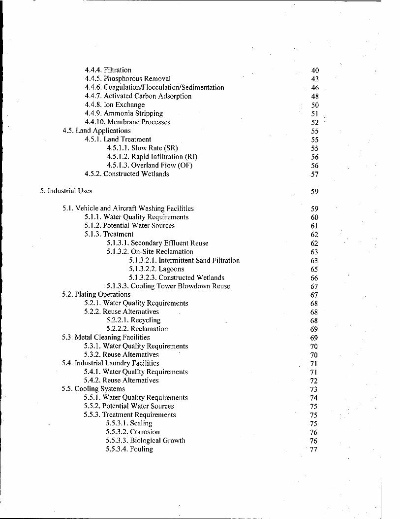
TABLE OF CONTENTS
Page
1. Background and Introduction 1
1.1. Purpose and Scope 1 1.2. The Need for Water Reuse 4
2. U.S. Navy Water Conservation Program 7
2.1. Executive Order 12902 7 2.2. Executive Order 13123 9
3. Legal Issues 11
3.1. Federal Environmental Regulations 11 3.1.1. National Environmental Policy Act 12 3.1.2. Clean Water Act 14 3.1.3. Safe Drinking Water Act 16
3.2. State Level Water Reuse Regulations 17 3.3. EPA Recommended Guidelines for Water Reuse 20 3.4. Water Rights 21
4. Water Treatment Processes 23
4.1. Preliminary Treatment 23 4.1.1. Screening 24 4.1.2. Comminution 24 4.1.3. Grit Removal 25 4.1.4. Flow Equalization 25
4.2. Primary Treatment 26 4.3. Secondary Treatment 28
4.3.1. Aerobic Biological Treatment 28 4.3.1.1. High-Rate Processes 28
4.3.1.1.1. Activated Sludge 29 4.3.1.1.2. Trickling Filters 29 4.3.1.1.3. Rotating Biological Contactors 30
4.3.1.2. Low-Rate Processes 31 4.3.1.2.1. Aerated Lagoons 31 4.3.1.2.2. Stabilization Ponds 32
4.3.2. Secondary Sedimentation 33 4.4. Advanced Treatment 34
4.4.1. Disinfection 34 4.4.2. Nitrification 38 4.4.3. Denitrification 39
4.4.4. Filtration 40 4.4.5. Phosphorous Removal 43 4.4.6. Coagulation/Flocculation/Sedimentation 46 4.4.7. Activated Carbon Adsorption 48 4.4.8. Ion Exchange 50 4.4.9. Ammonia Stripping 51 4.4.10. Membrane Processes 52
4.5. Land Applications 55 4.5.1. Land Treatment 55
4.5.1.1. Slow Rate (SR) 55 4.5.1.2. Rapid Infiltration (RI) 56 4.5.1.3. Overland Flow (OF) 56
4.5.2. Constructed Wetlands 57
5. Industrial Uses 59
5.1. Vehicle and Aircraft Washing Facilities 59 5.1.1. Water Quality Requirements 60 5.1.2. Potential Water Sources 61 5.1.3. Treatment 62
5.1.3.1. Secondary Effluent Reuse 62 5.1.3.2. On-Site Reclamation 63
5.1.3.2.1. Intermittent Sand Filtration 63 5.1.3.2.2. Lagoons 65 5.1.3.2.3. Constructed Wetlands 66
5.1.3.3. Cooling Tower Slowdown Reuse 67 5.2. Plating Operations 67
5.2.1. Water Quality Requirements 68 5.2.2. Reuse Alternatives 68
5.2.2.1. Recycling 68 5.2.2.2. Reclamation 69
5.3. Metal Cleaning Facilities 69 5.3.1. Water Quality Requirements 70 5.3.2. Reuse Alternatives 70
5.4. Industrial Laundry Facilities 71 5.4.1. Water Quality Requirements 71 5.4.2. Reuse Alternatives 72
5.5. Cooling Systems 73 5.5.1. Water Quality Requirements 74 5.5.2. Potential Water Sources 75 5.5.3. Treatment Requirements 75
5.5.3.1. Scaling 75 5.5.3.2. Corrosion 76 5.5.3.3. Biological Growth 76 5.5.3.4. Fouling 77
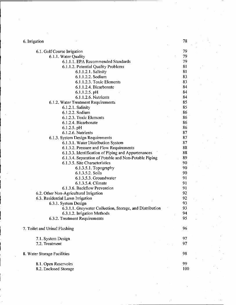
6. Irrigation - 78
6.1. Golf Course Irrigation 79 6.1.1. Water Quality 79
6.1.1.1. EPA Recommended Standards 79 6.1.1.2. Potential Quality Problems 81
6.1.1.2.1. Salinity 81 6.1.1.2.2. Sodium 83 6.1.1.2.3. Toxic Elements 83 6.1.1.2.4. Bicarbonate 84 6.1.1.2.5. pH 84 6.1.1.2.6. Nutrients 84
6.1.2. Water Treatment Requirements 85 6.1.2.1. Salinity 85 6.1.2.2. Sodium 86 6.1.2.3. Toxic Elements 86 6.1.2.4. Bicarbonate 86 6.1.2.5. pH 86 6.1.2.6. Nutrients 87
6.1.3. System Design Requirements 87 6.1.3.1. Water Distribution System 87 6.1.3.2. Pressure and Flow Requirements 88 6.1.3.3. Identification of Piping and Appurtenances 88 6.1.3.4. Separation of Potable and Non-Potable Piping 89 6.1.3.5. Site Characteristics 90
6.1.3.5.1. Topography 90 6.1.3.5.2. Soils 90 6.1.3.5.3. Groundwater 91 6.1.3.5.4. Climate 91
6.1.3.6. Backflow Prevention 91 6.2. Other Non-Agricultural Irrigation 92 6.3. Residential Lawn Irrigation 92
6.3.1. System Design 93 6.3.1.1. Greywater Collection, Storage, and Distribution 93 6.3.1.2. Irrigation Methods 94
6.3.2. Treatment Requirements 95
7. Toilet and Urinal Flushing 96
7.1. System Design 97 7.2. Treatment 97
8. Water Storage Facilities 98
8.1. Open Reservoirs 99 8.2. Enclosed Storage 100
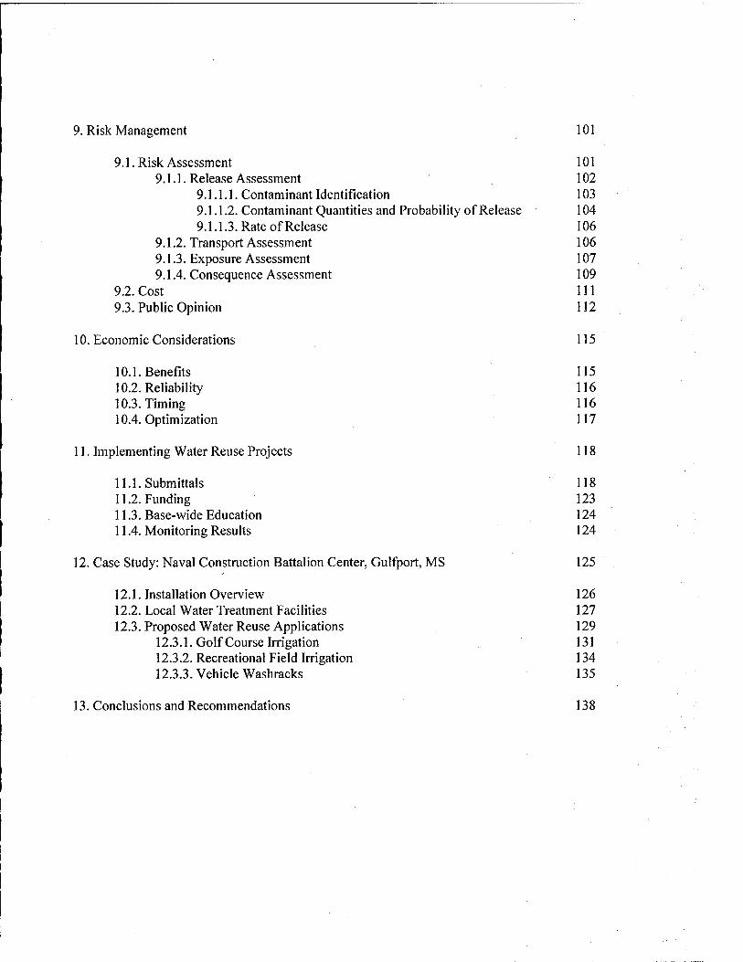
9. Risk Management 101
9.1. Risk Assessment 101 9.1.1. Release Assessment 102
9.1.1.1. Contaminant Identification 103 9.1.1.2. Contaminant Quantities and Probability of Release 104 9.1.1.3. Rate of Release 106
9.1.2. Transport Assessment 106 9.1.3. Exposure Assessment 107 9.1.4. Consequence Assessment 109
9.2. Cost 111 9.3. Public Opinion 112
10. Economic Considerations 115
10.1. Benefits 115 10.2. Reliability 116 10.3. Timing 116 10.4. Optimization 117
11. Implementing Water Reuse Projects 118
ll.l.Submittals 118 11.2. Funding 123 11.3. Base-wide Education 124 11.4. Monitoring Results 124
12. Case Study: Naval Construction Battalion Center, Gulfport, MS 125
12.1. Installation Overview 126 12.2. Local Water Treatment Facilities 127 12.3.Proposed Water Reuse Applications 129
12.3.1. Golf Course Irrigation 131 12.3.2. Recreational Field Irrigation 134 12.3.3. Vehicle Washracks 135
13. Conclusions and Recommendations 138
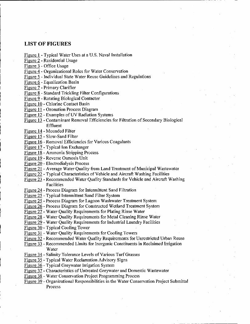
LIST OF FIGURES
Figure 1 - Typical Water Uses at a U.S. Naval Installation Figure 2 - Residential Usage Figure 3 - Office Usage Figure 4 - Organizational Roles for Water Conservation Figure 5 - Individual State Water Reuse Guidelines and Regulations Figure 6 - Equalization Basin Figure 7 - Primary Clarifier Figure 8 - Standard Trickling Filter Configurations Figure 9 - Rotating Biological Contactor Figure 10 - Chlorine Contact Basin Figure 11 - Ozonation Process Diagram Figure 12 - Examples of UV Radiation Systems Figure 13 - Contaminant Removal Efficiencies for Filtration of Secondary Biological
Effluent Figure 14 - Mounded Filter Figure 15 - Slow-Sand Filter Figure 16 - Removal Efficiencies for Various Coagulants Figure 17 - Typical Ion Exchanger Figure 18 - Ammonia Stripping Process Figure 19 - Reverse Osmosis Unit Figure 20 - Electrodialysis Process Figure 21 - Average Water Quality from Land Treatment of Municipal Wastewater Figure 22 - Typical Characteristics of Vehicle and Aircraft Washing Facilities Figure 23 - Recommended Water Quality Standards for Vehicle and Aircraft Washing
Facilities Figure 24 - Process Diagram for Intermittent Sand Filtration Figure 25 - Typical Intermittent Sand Filter System Figure 25 - Process Diagram for Lagoon Washwater Treatment System Figure 26 - Process Diagram for Constructed Wetland Treatment System Figure 27 - Water Quality Requirements for Plating Rinse Water Figure 28 - Water Quality Requirements for Metal Cleaning Rinse Water Figure 29 - Water Quality Requirements for Industrial Laundry Facilities Figure 30 - Typical Cooling Tower Figure 31 - Water Quality Requirements for Cooling Towers Figure 32 - Recommended Water Quality Requirements for Unrestricted Urban Reuse Figure 33 - Recommended Limits for Inorganic Constituents in Reclaimed Irrigation
Water Figure 34 - Salinity Tolerance Levels of Various Turf Grasses Figure 35 - Typical Water Reclamation Advisory Signs Figure 36 - Typical Greywater Irrigation System Figure 37 - Characteristics of Untreated Greywater and Domestic Wastewater Figure 38 - Water Conservation Project Programming Process Figure 39 - Organizational Responsibilities in the Water Conservation Project Submittal
Process
Figure 40 - Mississippi Precipitation Statistics: 1993 to Present Figure 41 - Aerial Photo of NCBC Gulfport, MS Figure 41 - Aerial Photo of NCBC Gulfport, MS Figure 42 - Aerial Photo of Gulfport South W WTP Figure 43 - Typical Water Quality at Gulfport South WWTP Figure 44 - Comparison of Water Quality at Gulfport South WWTP to EPA Recommended
Standards for Unrestricted Urban Reuse Figure 45 - Comparison of Water Quality at Gulfport South WWTP, EPA Recommended
Standards for Unrestricted Urban Reuse, and Washrack Requirements
APPENDICES
Appendix I - Gbssary Appendix II - EPA Recommended Guidelines for Water Reuse Appendix 111 - Irrigation System for the Front Nine Holes at Pine Bayou Golf Course, NCBC
Gulfport, MS Appendix IV - Irrigation System for the Back Nine Holes at Pine Bayou Golf Course, NCBC
Gulfport, MS Appendix V - References
1. BACKGROUND AND INTRODUCTION
1.1. PURPOSE AND SCOPE
For many years, potable water has been considered a renewable resource. It is cheap and
abundant in many areas of the U.S., and most people take for granted that it will flow freely
every time they turn on the tap. In the past 30 years, however, the Federal Government has taken
a closer look at water use and conservation practices. Passage of environmental legislation such
as the National Environmental Policy Act, Clean Water Act, and Safe Drinking Water Act have
forced public and private agencies alike to reconsider how they use and dispose of water. More
recently, President William J. Clinton signed Executive Order 12902, followed by Executive
Order 13123 as a follow-on to the 1992 Energy Policy Act. These orders forced Federal
agencies to develop water conservation programs and implement water conservation measures
for all Federal facilities. One of the options designated as a best management practice for water
conservation under Executive Order 13123 is water reuse and recycling.
This paper addresses the various issues that Navy facility planners must consider when
attempting to implement water reuse projects on Naval installations. Only non-potable uses are
considered, since the vast majority of potable water consumed on a base is not for potable
(consumption) use. Rather, it is used for various industrial, commercial, residential, and sanitary
applications. Further, the expense and lack public acceptance regarding water reuse for potable
purposes often makes this option impractical. As such, potable reuse is not addressed in this
paper. For purposes of discussion, the terms "Naval installations" and "Navy installations" refer
to U.S. Navy and Marine Corps-owned facilities operated and managed by the Naval Facilities
Engineering Command (NAVFAC) within the continental United States and around the world.
To date, no definitive guidance has been published by NAVFAC or other authority
specifically addressing planning and implementation of water reuse projects. Existing water and
energy conservation publications refer to water reuse as one of many design alternatives, but
only with limited detail. Altbugh water reuse is not new, a number of complex factors exist for
planning and executing projects of this nature. This report attempts to categorize these issues
and develop baseline guidance for Navy facility and energy managers regarding water reuse
applications. Sections 2 through 11 of this paper are organized to illustrate each distinct aspect
of the water reuse planning and implementation process. Each section is briefly described
below:
• Section 2 - U.S. Navy Water Conservation Program: This section addresses the various
aspects of the U.S. Navy Water Conservation Program as they relate to water reuse.
Specifically, the scope of Executive Orders 12902 and 13123 are discussed as well as key
milestones and best management practices they set forth.
• Section 3 - Legal Issues: Compliance with Federal, state, and local environmental
regulations with respect to water reuse are discussed. A brief review of the existence and degree
of state laws regulating water reuse is included. Finally, water rights considerations when
planning reuse projects are examined.
• Section 4 - Water Treatment Processes: This section describes the various processes that
may be used as part of a treatment scheme to improve the quality of reclaimed water to meet
Federal or state quality standards. Four distinct categories of treatment, including pretreatment,
primary treatment, secondary treatment, and advanced treatment are evaluated.
• Section 5 - Industrial Uses: Major industrial functions on Naval installations are
evaluated for potential water reuse applications. They include: vehicle and aircraft washing
facilities, plating operations, metal cleaning facilities, industrial laundry facilities, and cooling
systems.
• Section 6 - Irrigation: Irrigation options using secondary municipal wastewater effluent
and reclaimed greywater are considered for residential and commercial applications.
• Section 7 - Toilet and Urinal Flushing: Design of greywater collection and treatment
systems for toilet and urinal flushing in office and industrial facilities is evaluated in this section.
• Section 8 - Water Storage Facilities: Open and enclosed water storage facilities for reuse
applications are described in this section.
• Section 9 - Risk Management: Procedures for analyzing the three major factors in a risk
management decision; risk assessment, costs, and public opinion are described.
• Section 10 - Economic Considerations: Major economic considerations of a water reuse
project include: benefits, reliability, timing, and optimization. Each is addressed in this section.
• Section 11 - Implementing Water Reuse Projects: The steps that planners must take to
implement water reuse projects are described. Sources of funding, submittal requirements,
education, and monitoring results are all discussed.
The last two sections of the paper are a synthesis of ideas and issues discussed in Sections
1 through 11. Section 12 is a case study of the U.S. Naval Construction Battalion Center,
Gulfport, MS that evaluates various options for water reuse at that installation. Finally, Section
13 includes conclusions drawn about the planning and implementation process, along with
recommendations for the future of water reuse at Naval installations.
A number of technical terms are used throughout this report to describe the various
processes and applications related to water reuse. They are defined in Appendix I.
] .2. THE NEED FOR WATER REUSE
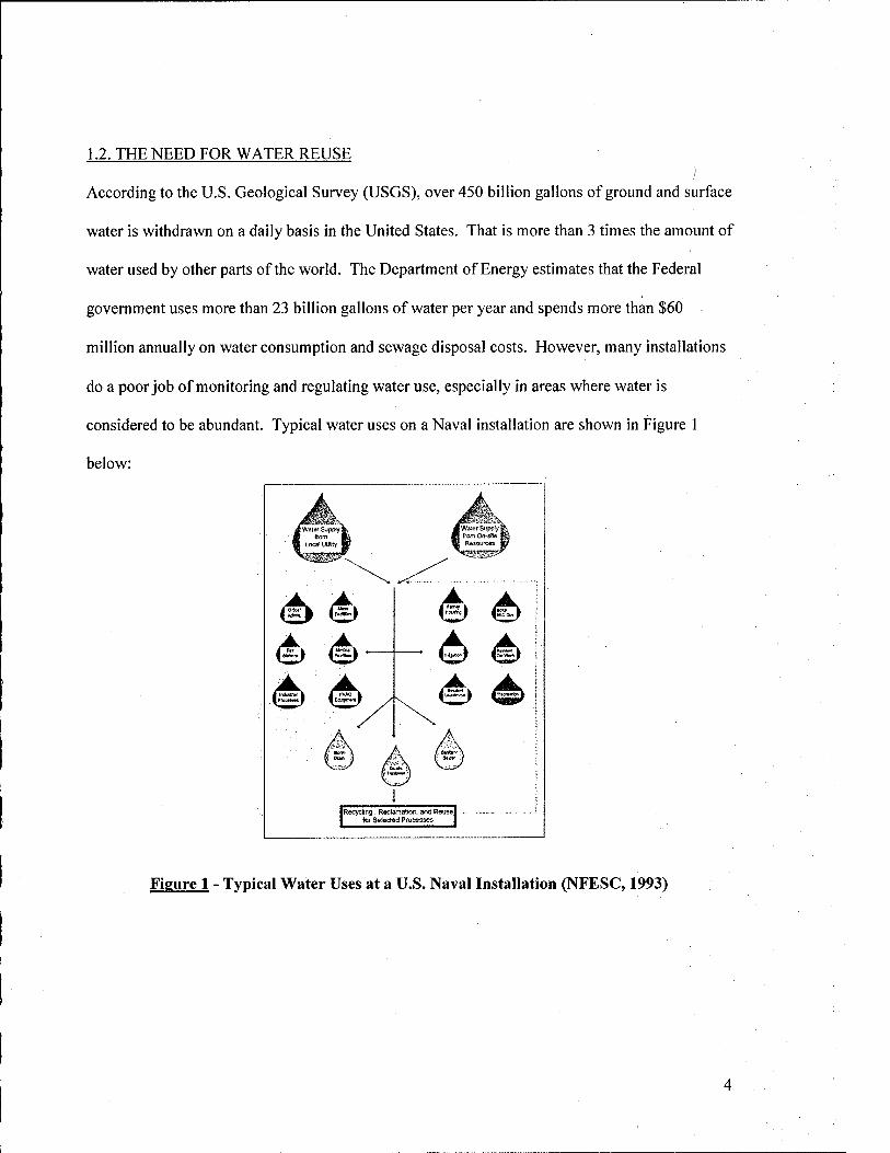
According to the U.S. Geological Survey (USGS), over 450 billion gallons of ground and surface
water is withdrawn on a daily basis in the United States. That is more than 3 times the amount of
water used by other parts of the world. The Department of Energy estimates that the Federal
government uses more than 23 billion gallons of water per year and spends more than $60
million annually on water consumption and sewage disposal costs. However, many installations
do a poor job of monitoring and regulating water use, especially in areas where water is
considered to be abundant. Typical water uses on a Naval installation are shown in Figure 1
below:
Figure 1 - Typical Water Uses at a U.S. Naval Installation (NFESC, 1993)
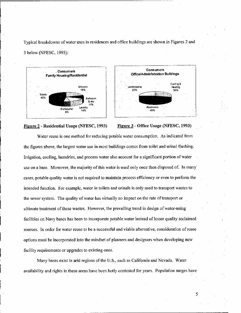
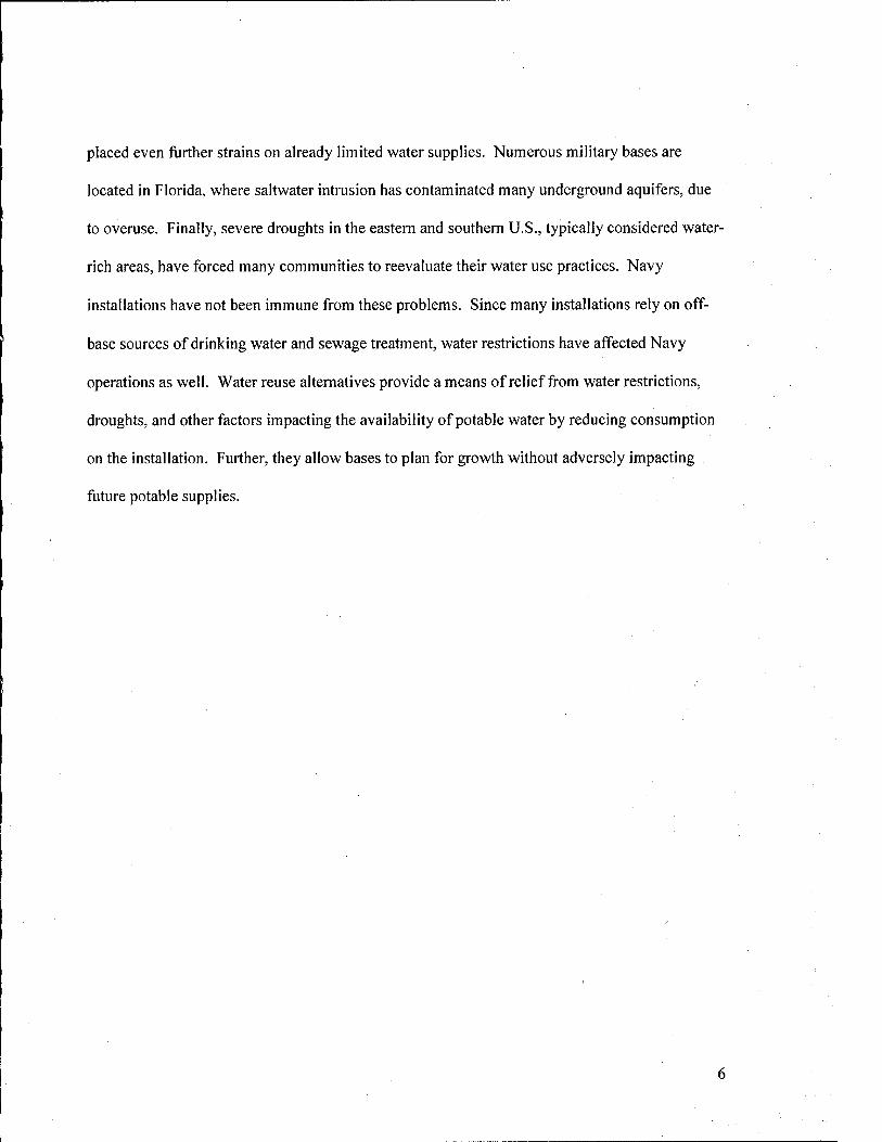
Typical breakdowns of water uses in residences and office buildings are shown in Figures 2 and
3 below (NFESC, 1993):
Consumers ■~— . i
1
Family Housing/Residential i )
Showers 19%
ToiHs ^ggniH ^^^ 45% ^^^■■rc"*" ̂ JH Bathroom
^^^^^^CsmTf-"' 1 Sinks ^^^mm ,—-^ 11%
Dishivasher 6%
Laindry 14%
Consumers Office/Administration Buildings
Landscaping . 25%
Cooling & Healing
30%
Figure 2 - Residential Usage (NFESC, 1993) Figure 3 - Office Usage (NFESC, 1993)
Water reuse is one method for reducing potable water consumption. As indicated from
the figures above, the largest water use in most buildings comes from toilet and urinal flushing.
Irrigation, cooling, laundries, and process water also account for a significant portion of water
use on a base. Moreover, the majority of this water is used only once then disposed of In many
cases, potable quality water is not required to maintain process efficiency or even to perform the
intended function. For example, water in toilets and urinals is only used to transport wastes to
the sewer system. The quality of water has virtually no impact on the rate of transport or
ultimate treatment of these wastes. However, the prevailing trend in design of water-using
facilities on Navy bases has been to incorporate potable water instead of lesser quality reclaimed
sources. In order for water reuse to be a successful and viable alternative, consideration of reuse
options must be incorporated into the mindset of planners and designers when developing new
facility requirements or upgrades to existing ones.
Many bases exist in arid regions of the U.S., such as California and Nevada. Water
availability and rights in these areas have been hotly contested for years. Population surges have
placed even further strains on already limited water supplies. Numerous military bases are
located in Florida, where saltwater intrusion has contaminated many underground aquifers, due
to overuse. Finally, severe droughts in the eastern and southern U.S., typically considered water-
rich areas, have forced many communities to reevaluate their water use practices. Navy
installations have not been immune from these problems. Since many installations rely on off-
base sources of drinking water and sewage treatment, water restrictions have affected Navy
operations as well. Water reuse alternatives provide a means of relief from water restrictions,
droughts, and other factors impacting the availability of potable water by reducing consumption
on the installation. Further, they allow bases to plan for growth without adversely impacting
future potable supplies.
2. U.S. NAVY WATER CONSERVATION PROGRAM
In 1992, the U.S. Congress passed the Energy Policy Act. This was the first of many
steps taken to reduce energy and utilities consumption at Federal facilities. It was soon followed
by Executive Order 12902 in 1994, which established the Federal Energy Management Program.
The Department of Energy (DOE) and General Services Administration (GSA) were placed in
charge of this program. NAVFAC has been assigned as the lead agent for energy and water
conservation programs and policies for the U.S. Navy. Within NAVFAC, the Naval Facilities
Engineering Service Center (NFESC) in Port Hueneme, CA serves as the primary point of
authority for all water and energy conservation related issues. The purpose of the Navy Water
Conservation Program is to develop methods to reduce water consumption on Naval facilities to
meet the goals set forth in Executive Order 12902 and most recently in Executive Order 13123.
Goals of the Navy Water Conservation Program are described in terms of the guidelines
established in each of these executive orders. While many water-saving measures are available
for use on Navy installations, only water reuse options are considered in the context of this
paper.
2.1. EXECUTIVE ORDER 12902
Executive Order 12902, "Energy Efficiency and Water Conservation at Federal
Facilities," was issued in March 1994. It mandates that all Federal agencies must take specific
actions to reduce energy and water consumption at federally owned facilities. Moreover, it
requires that energy consumption in Federal buildings be reduced by 30% from 1985 levels by
the year 2005. Although the central focus is on energy conservation, water conservation is
addressed as well. The primary agencies responsible for implementing Executive Order 12902
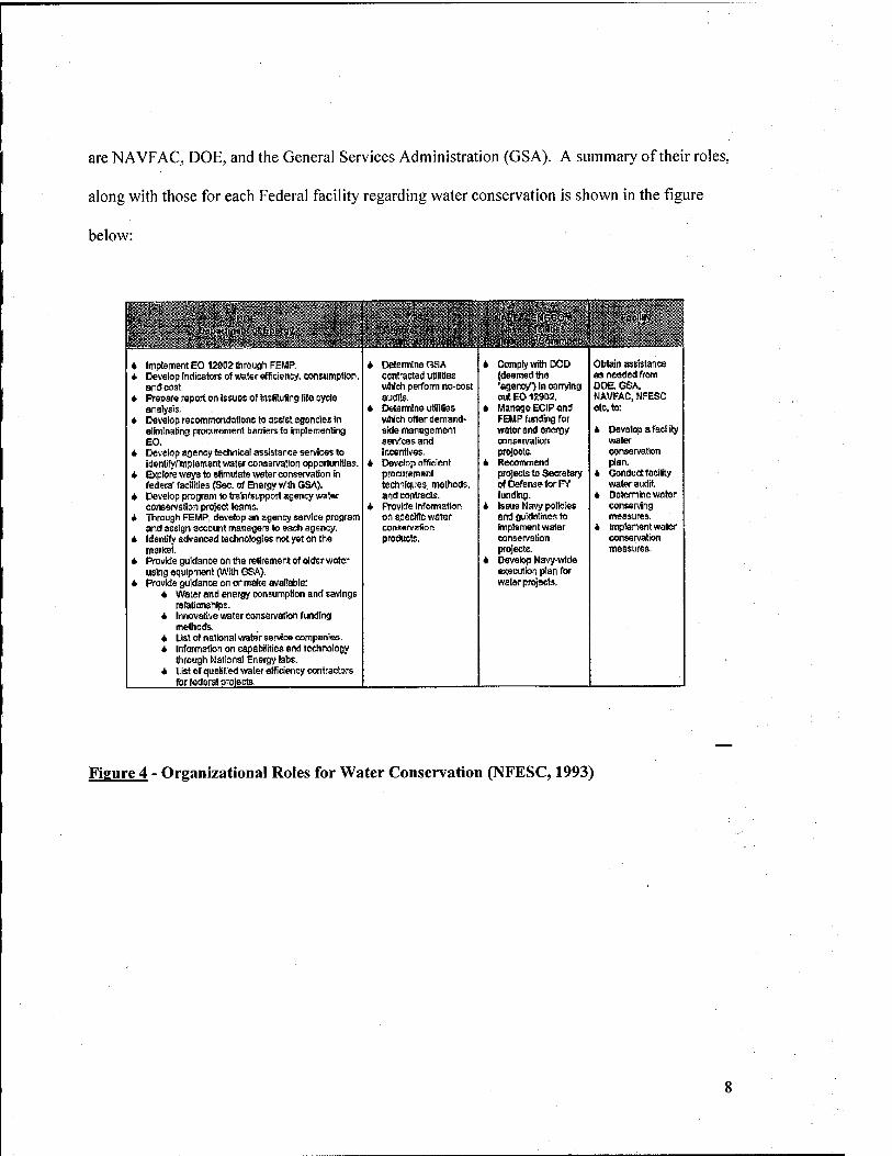
are NAVFAC, DOE, and the General Services Administration (GSA). A summary of their roles,
along with those for each Federal facility regarding water conservation is shown in the figure
below:
rrf, ■■ ■ ■■ £11. ••■ 1 t 1 ^' - "'J ■ ( 1 • -" :;, JcrJOS' - ' ;. ■. "feSA'tfe r>«iirAc;Hdcij'« - . Fcc.W§?, " ! * ' ' ,^mmoi*)ft-'>'itii' ' 'Vt' <S411&i^ ;$j^>li^sfn^> .jj 1 aciU'ics
I * ^tM^ - • — - Ai^*tli«tnt!}^l;''ik'*. ti'$ln''i ir^Coiin'-a t *■
i ImptementEO 12902 through FEMP. 4 Determine GSA 4 Comply With DOD Obtain assistance * Develop Indicators oJ water efficiency, consumption, contracted utililie$ (deemed the as needed from
and cost. which perfomi no-cost "agency") In oanylng DOE, GSA. * Prepare report on Issues of Itisfilufing lite cycle audits. outEOiZ9D2, NAVPAC.HI=FSC
analysis. 4 Determine uSliliss 4 Manage EClP and etc to: * Develop recommendations to assist agencies in which offer demand- FEMP funding for
eliminaBng procurement barriers to impSemenling side management water and energy 4 Develop 3 facility EO. services and oonseivalion water
4 Develop agency technical assistance services to incentives. projects. conservation idenlifyflrfiptement water consaivation opportgnifies. 4 Develop efficient 4 Recommend plan.
4 Explore ways to stimulate vrater oonsenraBon in procursmw^i projecls to Secretary 4 Conduct facility federal facilities fSec. of Energy with GSA). techniques, methods, of Defense for FY water audit.
4 Develop program to train/support agency water and coritracts. funding. 4 Determine water conservation project teams. 4 Provide Inforniation 4 Issue Navy policies conserving
4 Through FEMP, develop an agency service program on specific water and gutdetines to measures. and assign account managers to each agency. consen/afion implsment water 4 Implement water
4 Identify edvanr-.erf technologies not yet on the products. conservation conservation market. projects. measures.
4 Provide guidance on the reh'reinenl of older v/ater 4 Develop Navy-wide using equipment (With GSA). e>^cution plan for
4 provide guidance on or make available: water prajacts. * Water and energy consumption and savings
retalianships. 4 Innovattve water eonsenrafion funding
melhods. 4 list of national water service oompanias. 4 bifoimation on capabilities and technology
ttirough National Energy labs. 4 List of qualified water efficiency contractors
for federal prelects
Figure 4 - Organizational Roles for Water Conservation (NFESC, 1993)
2.2. EXECUTIVE ORDER 13123
In May 2000, Executive Order 13123, "Guidance to Establish Water Efficiency
Improvement Goal for Federal Agencies" was promulgated by President William J. Clinton,
which superseded Executive Order 12902. It states that all Federal agencies are required to
reduce potable water use on Federal facilities using life cycle cost-effective water efficiency
programs that include a water management plan. In addition, they must implement at least four
FEMP Water Efficiency Improvement Best Management Practices (BMP) as defined in the
order.
Water management plans must be developed for all Federal installations and should
indicate how a facility uses its water, all the way from the water source to disposal. The
following information must be included in a water management plan:
• Operation and maintenance recommendations
• Utility information, including points of contact, rate schedules, copies of water and sewer
bills dating back at least 2 years, sources of financial and technical assistance, and production
information.
• Facility information
• Emergency response information
• Comprehensive planning to incorporate all aspects of facility operation.
Executive Order 13123 outlines ten potential best management practices that agencies can
implement on Federal installations. They include:
• BMP # 1 - Public Information and Education Programs
• BMP # 2 - Distribution System Audits, Leak Detection & Repair
• BMP # 3 - Water Efficient Landscape
BMP # 4 - Toilets and Urinals
BMP # 5 - Faucets and Showerheads
BMP # 6 - Boiler/Steam Systems
BMP # 7 - Single-Pass Cooling Systems
BMP # 8 - Cooling Tower Systems
BMP # 9 - Miscellaneous High Water Using Processes
BMP #10- Water Reuse and Recycling
The primary emphasis of this paper is on planning and implementing projects in accordance with
BMP #10, "Water Reuse and Recycling". BMP #10 focuses on substitution of non-potable water
for uses that are currently served by potable supplies. Both treated secondary municipal
wastewater effluent and greywater sources should be considered for non-potable water reuse.
Treated secondary effluent is preferred over greywater, due to high capital costs associated with
retrofits and potential health concerns. However, greywater systems are considered in this paper
as potential options for residential irrigation and toilet/urinal flush water. BMP #10 also
recommends that non-potable reuse alternatives are included in the design of new facilities,
which is generally more cost effective than funding retrofits.
10
3. LEGAL ISSUES
There are a number of regulatory issues that must be addressed when planning a water
reuse project on a Navy installation. Federal environmental laws, namely the National
Environmental Policy Act, Clean Water Act, and Safe Drinking Water Act, will likely require
some level of compliance. While none of these laws specifically address water reuse, they all
regulate the impact of contaminant loading on the environment. Many states have implemented
water reuse regulations, which will apply depending on the location of the installation. Where
no state regulations apply, the U.S. Environmental Protection Agency (EPA) has developed
recommended water quality and planning guidelines for reuse applications. Finally, existing
water rights doctrine, especially in the Western U.S., may impact on the extent and nature of
water reuse projects. This section highlights the key areas of concern for installation planners as
they apply to water reuse.
3.1. FEDERAL ENVIRONMENTAL REGULATIONS
As stated above, no specific Federal laws explicitly regulate water reuse. However, due
to the nature of water reuse projects, they may fail under the jurisdiction of one or more Federal
environmental laws. The National Environmental Policy Act (NEPA), Clean Water Act (CWA),
and Safe Drinking Water Act (SDWA) are of primary concern. Since Navy installations are
federally controlled, NEPA compliance will be necessary. Further, many water reuse projects
rely on secondary municipal wastewater effluent, which is regulated under the Clean Water Act.
Finally, if groundwater or potable water supplies are potentially impacted by a water reuse
scheme, Safe Drinking Water Act requirements may apply. Each of these regulations is
discussed below:
3.1.1. National Environmental Policy Act
The National Environmental Policy Act was enacted in 1969 to establish a national
environmental policy that all Federal agencies must adhere to. Specifically, all Federal agencies
must consider the environmental consequences of all proposed legislation and other major
Federal actions. Major Federal actions include:
• Programs conducted, regulated or approved by the Federal government
• Projects entirely or partially financed with Federal funds
• New or revised policies, regulations, procedures, and legislative proposals
• Plans created to guide or specify use of Federal resources
Under NEPA, a detailed statement must be prepared to address significant environmental
effects resulting from proposed legislation or major Federal actions, alternatives to the proposed
actions, and the relationships between environmental damage and benefits from implementing
the proposed strategy. This document is known as an Environmental Impact Statement (EIS).
Preparation of an EIS is an extremely long, intensive, and costly process. Fortunately, there are
many instances where an EIS is not required.
Water reuse projects are defined as major Federal actions, since they are funded and
conducted by the government. The first step in determining whether a water reuse project is
subject to NEPA (specifically, whether an EIS is required), is to perform an Environmental
Assessment (EA). An EA is a 10-15 page document prepared to provide sufficient evidence and
analysis as to whether an EIS will be required. The impact of the proposed project and its
alternatives are reviewed to determine if there will be a significant impact on the environment as
a result of implementation. If no adverse impacts are discovered, the Navy may issue a Finding
of No Significant Impact (FONSI). The FONSI will satisfy NEPA requirements, without having
12
to perform an EIS. However, if potentially significant environmental impacts exist, an EIS will
need to be prepared (White, 2003; Kontos and Asano, 1996).
Some projects may be considered "categorical exclusions", in that they are specifically
exempted from NEPA requirements. Categorical exclusions do not require an EIS, but are very
limited. The Federal or state Council on Environmental Quality (CEQ) should be contacted
regarding categorical exclusions (White, 2003).
The standard format for an Environmental Impact Statement is as follows (Aston, 2003):
• Cover Sheet
• Summary
• Table of Contents
• Purpose of and Need for Action
• Alternatives Including Proposed Action
• Affected Environment
• Environmental Consequences
• List of Preparers
• List of Agencies, Organizations, and Persons to Whom Copies are Sent
• Index
• Appendices
The process of preparing an EIS is briefly described below (Kontos and Asano, 1996):
• Notice of Intent: A notice of intent must be published in the Federal Register. It includes
a description of the project, an overview of the scoping process, and key points of contact.
• Scoping: Scoping involves the determination of issues to be included in the EIS. This
typically involves public input and coordination with other agencies.
13
• Draft EIS: A Draft EIS must be prepared and sent for review by Federal and state
agencies with jurisdiction, expertise, or interest in the project. It must also be available to the
public, upon request. The review and comment period will last 45 days or more. The Draft EIS
is also filed with the EPA.
• Final EIS: After comments from the Draft EIS have been received, they are incorporated
into the Final EIS. The Final EIS must address all concerns and comments from the Draft EIS.
Copies of the Final EIS are sent to all reviewers of the draft EIS. A notice must be filed with
EPA, who will then publish it in the Federal Register. A 30-day review period is required to
make all necessary changes before the Final EIS can be adopted.
3.1.2. Clean Water Act
The Federal Water Pollution Control Act (also known as the Clean Water Act or CWA)
was promulgated by Congress in 1972. Its primary objective is to restore and maintain the
quality of U.S. waters to a level that provides for protection offish and wildlife and allows for
recreation in and on the water. The CWA specifically prohibits discharge of any pollutant by
any person into any navigable waters, unless an exception has been made. Navigable waters
refer to all "waters of the United States", including rivers, lakes, streams, impoundments,
tributaries, wetlands, and the like. Groundwater and water/wastewater treatment plants are not
considered navigable waters and are therefore not regulated under the CWA. Exceptions to the
no-discharge rule are normally handled through the National Pollution Discharge Elimination
System (NPDES). In order to discharge any quantity of pollutant into any navigable water, the
polluter must obtain an NPDES permit. For water reuse projects, this may be the local
wastewater treatment plant or the installation, depending on the nature of the project. NPDES
permits are administered by the state environmental authority (i.e. Maryland Department of the
14
Environment) and overseen by EPA. The permits will typically set numerical limits for the
concentration (i.e. mg/L) or total loading (i.e. g/yr) of pollutants that may be discharged into the
environment. Requirements are usually state-specific and are designed to maintain the quality of
a state's water bodies. However, they will be at least as stringent as EPA standards for
individual pollutants. Although CWA standards primarily address point source polluters (i.e.
pipes, culverts, etc.), provisions for non-point source pollution (i.e. runoff) also exist (White,
2003).
In many cases, water reuse projects are designed to reduce pollutant loading to navigable
waters by diverting some of the effluent from municipal wastewater treatment plants for use on
Navy installations. This strategy has two benefits. First, a reduction in pollutant loading allows
for future expansion of the treatment plant without obtaining another NPDES permit. Also, it
allows for reduction in potable water consumption by the base. However, if the installation does
not take appropriate measures to prevent discharge of the reuse water (treated or not) to
navigable waters, the Navy becomes liable under the Clean Water Act. In many cases, this
cannot be avoided and the installation must apply for an NPDES permit. For example, storage
ponds containing reclaimed water for golf course irrigation will require an NPDES permit. The
ponds, whether manmade or natural, pre-existing or not, are by definition navigable waters, and
therefore subject to the CWA. Input of reclaimed water, even if it is of higher quality relative to
existing water in the pond, can only be done with an NPDES permit.
Runoff is another concern when using water reuse applications on a base. Systems must
be designed to minimize or collect runoff to prevent contamination of surface waters. As
previously indicated, runoff is a non-point pollution source and subject to the CWA.
15
3.1.3. Safe Drinking Water Act
The Safe Drinking Water Act is designed to protect sources of drinking water and
regulate the systems that provide it. A number of provisions in the 1986 amendments to the
SDWA have potential implications for water reuse projects. Most importantly, maximum
contaminant levels (MCL) were established as health-based standards to control contaminant
concentrations in drinking water. If these standards are exceeded, the municipality or installation
(depending on who controls the drinking water source) may be liable. Two applicable programs
designed to enhance groundwater protection were also included in the 1986 SDWA amendments.
They are the Underground Injection Control Program (UICP) and the Sole-Source Aquifer
Program (SSAP). The UICP is designed to protect usable aquifers and regulates the use of
injection wells. The SSAP prohibits the use of Federal funds on projects that may contaminate
critical potable aquifers (White, 2003).
Land use applications, such as irrigation and non-potable aquifer storage, will frequently
face SDWA compliance issues. For example, many states strictly regulate nitrogen in
groundwater, due to its deleterious effects on water quality. Unless nitrogen can be removed in
treatment to extremely low levels, irrigation with reclaimed water may cause MCLs to be
exceeded. This is also true for other contaminants that may be present in wastewater and
introduced to drinking water sources. Non-potable aquifer storage has been considered as an
efficient means for storing reclaimed water for later use. However, the potential to contaminate
nearby potable aquifers will often prevent their use. Further, under the SSAP, if there is a
potential to contaminate potable aquifers, the project cannot legally be funded. In order to
overcome these regulatory hurdles, treatment processes must be designed to reduce contaminants
16
in municipal wastewater effluent or greywater sources to acceptable levels. Treatment options
are described in detail in Section 4.
3.2. STATE LEVEL WATER REUSE REGULATIONS
A number of states have developed regulations regarding water reuse in their
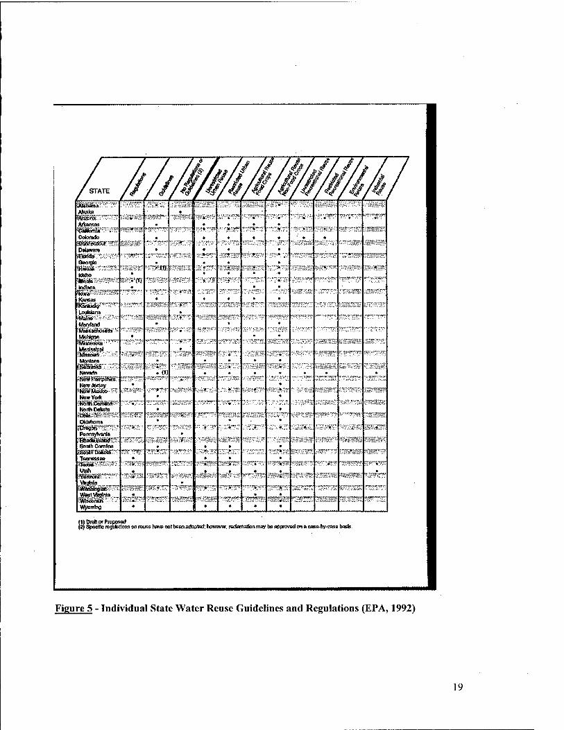
jurisdictions. As of 1992, 18 of the 50 states had specific regulations, 18 others had guidelines or
design standards, while 14 had no standards. State regulations and guidance documents are
typically broken down into several categories, including (EPA, 1992):
• Water Quality and Treatment Requirements: The most common reuse regulations involve
water quality and treatment requirements. Unrestricted urban reuse typically has the highest
standards, due to the high exposure potential. Other uses, where public exposure is less likely,
generally have less stringent standards. BOD, TSS, coliforms, and turbidity are the most
common water quality parameters included in state water reuse regulations.
• Monitoring Requirements: Monitoring involves routine examination of water quality
parameters, such as turbidity and fecal coliforms, to ensure that the reuse system is operating
correctly and treatment processes are effectively reducing contaminant levels to within
regulatory standards.
• Treatment Facility Reliability: Many states have incorporated reliability provisions into
water reuse regulations. The purpose of these provisions is to ensure that treatment systems are
operating at all times and to minimize bypass or flow-through potential, due to treatment system
inoperability. Reliability regulations include use of alarms for warning of power or essential
systems failures, use of automatic standby power, emergency storage, and redundant systems for
treatment processes.
17
• Minimum Storage Requirements: Minimum storage requirements are implementeid to
limit or prevent surface water discharge of treated reuse water. Most states do not differentiate
between operational and seasonal storage.
• Application Rates: Application rate requirements typically pertain to land application
uses (i.e. land treatment, irrigation, etc.). They are normally set well above irrigation demands,
since the intent of water reuse is to reduce discharges to water bodies. As such, the more treated
water that is applied to land, the better. Many states have limits on nitrogen loading, due to
potential groundwater contamination.
• Groundwater Monitoring: Many states require groundwater monitoring, especially for
land application uses. At least one well is required to be placed up-gradient of the reuse site to
observe background conditions. Typically, at least two or more wells must be placed down-
gradient from the site to assess water quality and contaminant transport. The primary focus of a
groundwater-monitoring program is the quality of aquifers close to the surface, since they have
the highest potential for being adversely affected by water reuse.
• Setback Distances: Often, setback distances or buffer zones will be required between
irrigation sites and potable wells, property lines, residential areas, and roadways in order to
minimize the potential for human contact with reclaimed water.
A summary of guidelines and regulations for each of the 50 states is shown on the following
page. Individual state environmental regulatory agencies should be contacted for specific
guidance regarding each of these requirements.
18
/- ////MMMMM . / / 1 /^ /
;jUab;<na » ♦
Atasta * <Anj»na Ailcansas
)» ■
• « • *
4 ^«^ *" • *
^tem1a~ w ^ w^^ » V" r""-— "" » ' J( «^ >^M^« « ■"• ■* ■> "t*
Colomda • « * ♦ « * -jSiwrMiat '-"
n * - ^ ^ ( -rJ-- ""' ■"■ / ■ "■
Delaware * « « Flotda ♦«* - « ■»■ ■r V N- W,
■^ ■"^ • ■ . J w ■
Qeorgia • « • 'HaiAa! ' "' f *t1) A " r n • ^' v ^ JK
_•**» * « • • MnooB ' -.fl) ™ " t * '"" "" ♦ " '"' ^»l-- ■ rt---f* ^^H ? ^ W
« . ^ • • ■^ 0. --MJ- , I- ^ " >* 't- -
Hfc-** * Knn$as • • » • •
»3l&ijdl<)r 1 •" ■* i"""^
,^ - ' LotimajiA •
'Wslna - ♦ "■ ' }" ^ "' -^ ^ i^ W^ •v
Msrytend • • » m,^d»itiii» • " V- ..-..-, ^ ™
iiSSfflwota
* _ *
^ v^
• ^* ^ w „_^^
.Mbslsstpd » 'MssoUfi ♦ »- f-
MontsAa • « ■ ♦
$i>^tei » ^ * ~*^ » ■ " "^ *" '' ^ NsvKb .(» * • • • • »
?«<Wfl5Ki»lhS« " - , * * -V T - ~. , t"-^" * *■} M*i f. i 1 **"'' ¥ '-
New JerS^ • HfSkUsSm f ' •- * » f ' -M -T~f_
Nswy««c • ^)lgfiii'£^illft»
f, - " "*" ""'■ .i"
■' "■ -^ » I y*
North DiAota • isasKssf """ " ^ » jir- - f ■" "* -»* "" ^«y « » >« J^ V.1-
OKlnhoma » .
• 1 " ^ - » ' t ^ * " f0«^|&S'^^ * • , -.j !/mmmM ^ »"'"'" " *- -, - " 5 ■' r
SoiMhCaroltna 9 • R
,S6lffliBskcM- ^ T l-V f) tl ** * *" ** T-f' "•*r"- ^ •'*v5* " *
Tenne»t» * * » -Tttfc.'-" ■ '* """ ' ^" • -~* ( >.^ ^ ""'• ^■^ " * -^ " "" » ^ Utah • * . • • (Wmwft "' ' " * *.. "^"^ ^ • " r-r-v^^ V. > %[* ■" 1 »--r
Virginia • ■meiikiglan «« """ r' • "" "*"* •■"
" ^trr »-^ ■^ * " * "»^ '^'"* ''^ "^ <I-*r LflY iT
i^^"" ' • * ... — - ' «.^ w • --; . — ""' i-" ^... k •"?«■"•* -
* • • ♦
mDraHcrrPniDoeKi (2) SpsclBc regutelforB on reuse hars not been atpted; howOTar, redarta&n may be approved on « eauft-by-case hseis.
Fi2ure 5 - Individual State Water Reuse Guidelines and Regulations (EPA, 1992)
19
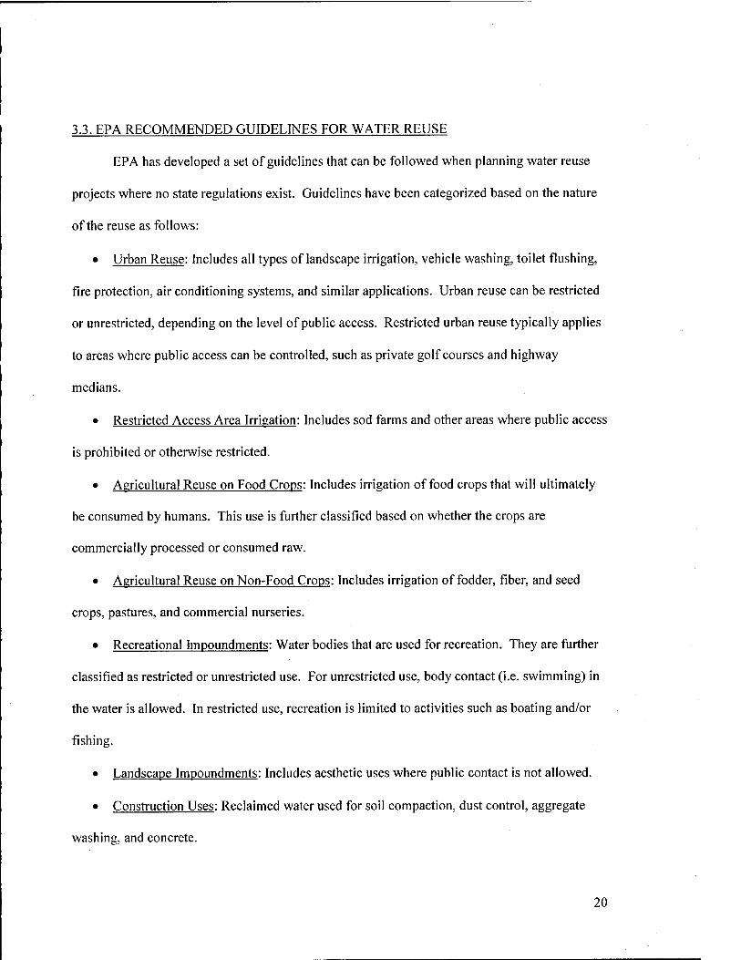
3.3. EPA RECOMMENDED GUIDELINES FOR WATER REUSE
EPA has developed a set of guidelines that can be followed when planning water reuse
projects where no state regulations exist. Guidelines have been categorized based on the nature
of the reuse as follows:
• Urban Reuse: Includes all types of landscape irrigation, vehicle washing, toilet flushing,
fire protection, air conditioning systems, and similar applications. Urban reuse can be restricted
or unrestricted, depending on the level of public access. Restricted urban reuse typically applies
to areas where public access can be controlled, such as private golf courses and highway
medians.
• Restricted Access Area Irrigation: Includes sod farms and other areas where public access
is prohibited or otherwise restricted.
• Agricultural Reuse on Food Crops: Includes irrigation of food crops that will ultimately
be consumed by humans. This use is further classified based on whether the crops are
commercially processed or consumed raw.
• Agricultural Reuse on Non-Food Crops: Includes irrigation of fodder, fiber, and seed
crops, pastures, and commercial nurseries.
• Recreational Impoundments: Water bodies that are used for recreation. They are further
classified as restricted or unrestricted use. For unrestricted use, body contact (i.e. swimming) in
the water is allowed. In restricted use, recreation is limited to activities such as boating and/or
fishing.
• Landscape Impoundments: Includes aesthetic uses where public contact is not allowed.
• Construction Uses: Reclaimed water used for soil compaction, dust control, aggregate
washing, and concrete.
20
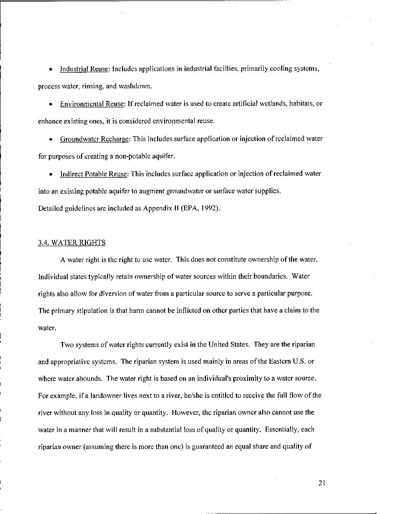
• Industrial Reuse: Includes applications in industrial faciliies, primarily cooling systems,
process water, rinsing, and washdown.
• Environmental Reuse: If reclaimed water is used to create artificial wetlands, habitats, or
enhance existing ones, it is considered environmental reuse.
• Groundwater Recharge: This includes surface application or injection of reclaimed water
for purposes of creating a non-potable aquifer.
• Indirect Potable Reuse: This includes surface application or injection of reclaimed water
into an existing potable aquifer to augment groundwater or surface water supplies.
Detailed guidelines are included as Appendix II (EPA, 1992).
3.4. WATER RIGHTS
A water right is the right to use water. This does not constitute ownership of the water.
Individual states typically retain ownership of water sources within their boundaries. Water
rights also allow for diversion of water from a particular source to serve a particular purpose.
The primary stipulation is that harm cannot be inflicted on other parties that have a claim to the
water.
Two systems of water rights currently exist in the United States. They are the riparian
and appropriative systems. The riparian system is used mainly in areas of the Eastern U.S. or
where water abounds. The water right is based on an individual's proximity to a water source.
For example, if a landowner lives next to a river, he/she is entitled to receive the full flow of the
river without any loss in quality or quantity. However, the riparian owner also cannot use the
water in a manner that will result in a substantial loss of quality or quantity. Essentially, each
riparian owner (assuming there is more than one) is guaranteed an equal share and quality of
21
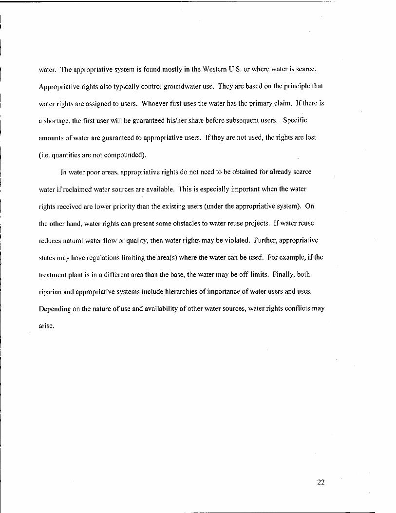
water. The appropriative system is found mostly in the Western U.S. or where water is scarce.
Appropriative rights also typically control groundwater use. They are based on the principle that
water rights are assigned to users. Whoever first uses the water has the primary claim. If there is
a shortage, the first user will be guaranteed his/her share before subsequent users. Specific
amounts of water are guaranteed to appropriative users. If they are not used, the rights are lost
(i.e. quantities are not compounded).
In water poor areas, appropriative rights do not need to be obtained for already scarce
water if reclaimed water sources are available. This is especially important when the water
rights received are lower priority than the existing users (under the appropriative system). On
the other hand, water rights can present some obstacles to water reuse projects. If water reuse
reduces natural water flow or quality, then water rights may be violated. Further, appropriative
states may have regulations limiting the area(s) where the water can be used. For example, if the
treatment plant is in a different area than the base, the water may be off-limits. Finally, both
riparian and appropriative systems include hierarchies of importance of water users and uses.
Depending on the nature of use and availability of other water sources, water rights conflicts may
arise.
22
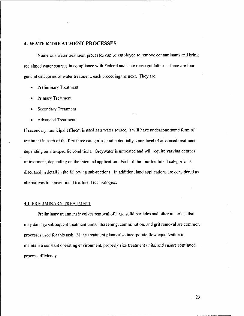
4. WATER TREATMENT PROCESSES
Numerous water treatment processes can be employed to remove contaminants and bring
reclaimed water sources in compliance with Federal and state reuse guidelines. There are four
general categories of water treatment, each preceding the next. They are:
• Preliminary Treatment
• Primary Treatment
• Secondary Treatment
• Advanced Treatment
If secondary municipal effluent is used as a water source, it will have undergone some form of
treatment in each of the first three categories, and potentially some level of advanced treatment,
depending on site-specific conditions. Greywater is untreated and will require varying degrees
of treatment, depending on the intended application. Each of the four treatment categories is
discussed in detail in the following sub-sections. In addition, land applications are considered as
alternatives to conventional treatment technologies.
4.1. PRELIMINARY TREATMENT
Preliminary treatment involves removal of large solid particles and other materials that
may damage subsequent treatment units. Screening, comminution, and grit removal are common
processes used for this task. Many treatment plants also incorporate flow equalization to
maintain a constant operating environment, properly size treatment units, and ensure continued
process efficiency.
23
4.1.1. Screening
Typically the first process in a wastewater treatment scheme, the purpose of screening is
to remove large solid materials that could potentially damage the distribution system and
downstream treatment equipment, reduce treatment efficiency, and contaminate water bodies.
Influent passes through a metal screen with uniform openings, which retains the solid material.
Screen openings may be classified as coarse (6 to 150 mm), fine (< 6 mm), or micro (< 50 fxm),
depending on the size particles they are intended to remove. Coarse screens are generally
composed of parallel bars or rods, and are often referred to as "bar racks". Fine screens are
constructed of perforated plates or wire cloth. Screens may be either manually or mechanically
cleaned (Metcalf and Eddy, 2003).
4.1.2. Comminution
Comminution is an alternative to screening influent wastewater, wherein coarse solid
materials are grinded or shredded by mechanical units and subsequent treatment processes
remove the resulting particulates. The main advantage of comminution is that there are no
screens to be cleaned, which can often be an unpleasant task. There are three types of units
commonly used. They include comminutors, macerators, and grinders. Comminutors are used
primarily for small treatment systems (less than 5 MOD). They use a stationary horizontal
screen to intercept inflow and a rotating arm with cutting teeth to mesh with the screen.
Macerators operate at slow speeds with two sets of counter-rotational cutting assemblies.
Material is chopped up as it passes through the unit. Grinders are high-speed machines used in
conjunction with bar racks. A high speed rotating knife assembly cuts the materials received
from the bar racks. Wash water introduced into the unit keeps it clean and sends the shredded
material back into the wastewater stream (Metcalf and Eddy, 2003).
24
4.1.3. Grit Removal
Grit removal typically occurs after screening or comminution and before primary
treatment facilities. The purpose of this process is to remove inorganic solids (i.e. gravel, sand,
coffee grounds, etc.) from the wastewater, which may cause problems in subsequent treatment
units. Grit chambers are designed to only remove particles with specific gravity greater than 2.5
(most inorganic matter). Lighter organic particles are allowed to pass through for removal in
later processes. The types of grit chambers include horizontal flow, aerated, and vortex-type.
Horizontal flow chambers may be either rectangular or square. Influent enters one side of the
chamber and flows horizontally in the tank until it reaches a discharge weir. In aerated grit
chambers, air is pumped to one side of the tank, which creates a spiral flow perpendicular to the
wastewater flowing through the chamber. This process helps to increase grit removal efficiency,
and close to 100% removal can be achieved with these types of grit chambers. Finally, vortex-
type grit chambers employ a rotating turbine to create a vortex flow pattern to promote
separation of organic and inorganic material. The grit is then collected at the bottom of the tank
in a hopper (Hao, 2003; Metcalf and Eddy, 2003).
4.1.4. Flow Equalization
Flow equalization facilities are designed to achieve a constant flow rate into treatment
facilities. Incoming wastewater flows typically vary with time of day, season, and a number of
other factors. In order to maximize treatment efficiency, reduce shock loading, and design
correctly sized treatment units, flow equalization is often necessary. There are two types of
configurations that can be employed. The first is called on-line (or in-line) equalization. Here,
all of the incoming wastewater enters the basin and is discharged at a constant output rate. The
other type, called off-line equalization, is not directly in the treatment train. Instead, its use is
25
based on a predetermined average flow rate for the system. If the flow is higher than average,
the excess flow is diverted into the basin. If flow is below average, water is pumped from the
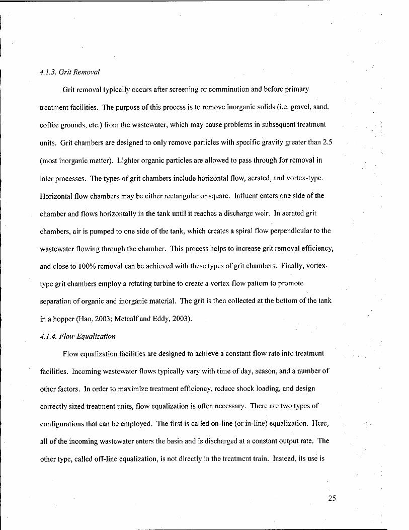
equalization basin to maintain constant flow (Hao, 2003; Metcalf and Eddy, 2003). A typical
equalization basin is shown in Figure 6 below:
Figure 6 - Equalization Basin
4.2. PRIMARY TREATMENT
Primary sedimentation is typically accomplished with rectangular or circular
sedimentation basins (clarifiers), which are designed to remove organic settleable solids and
floating material from the waste stream. In rectangular tanks, water flows over an influent weir
and along the length of the tank at a slow velocity, while solids settle on the tank bottom. Chain
and flight conveyors or traveling bridge type collectors are used to remove the settled material
from the tank for further processing and disposal. In circular tanks, influent can either be
introduced along the periphery of the tank or through an outlet at the center. Typically, the
former configuration (referred to as rim-feed) is used, because it produces higher removal
efficiency. A continuous effluent channel, composed of v-notch weirs is located approximately
26
75% of the radial distance from the tank center. Skimmers collect residue in the influent and
effluent channels and settled solids in the bottom of the basin are scraped to a center hopper,
where they are pumped to sludge treatment facilities. Some organic nitrogen, organic
phosphorous, and heavy metals may be removed during primary sedimentation. However, to
achieve contaminant concentrations acceptable by most EPA and state water reuse guidelines,
further treatment is almost always required. Addition of chemical coagulants, such as alum,
ferric chloride, and lime can increase the removal efficiency of these compounds. More
information on coagulants can be found in Section 4.4, Advanced Treatment (Metcalf and Eddy,
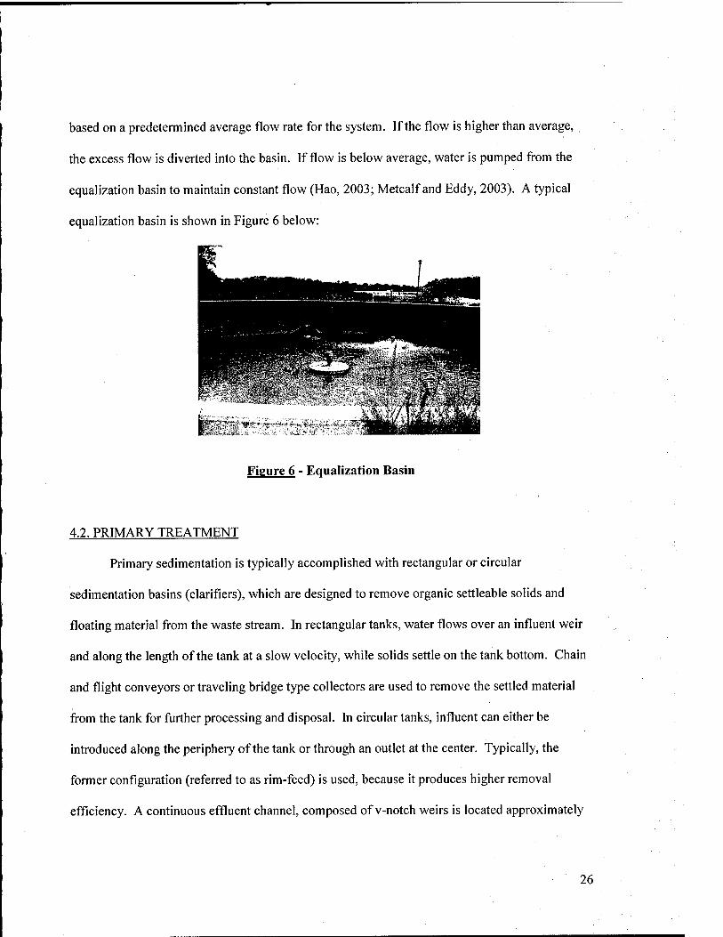
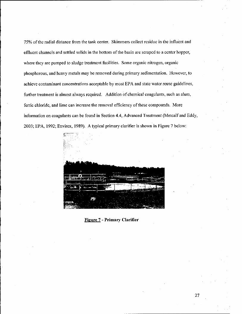
2003; EPA, 1992; Envirex, 1989). A typical primary clarifier is shown in Figure 7 below:
Figure 7 - Primary Clarifier
27
4.3. SECONDARY TREATMENT
Secondary treatment normally involves aerobic biological treatment followed by
secondary sedimentation. The primary purpose of secondary treatment is to reduce BOD and
nutrient content in the water. The most popular form of aerobic biological treatment is the
activated sludge process. To a lesser extent, trickling filters, rotating biological contactors,
aerated lagoons, and stabilization ponds may also be used. Sedimentation facilities are employed
to remove suspended material created during biological treatment and improve water quality.
4.3.1. Aerobic Biological Treatment
Aerobic biological treatment is performed to reduce organic matter (BOD),
microorganisms, and in some instances nitrogen and phosphorous in the water. As the name
suggests, this type of treatment is performed in an aerobic (oxygen-rich) environment, allowing
microorganisms in the treatment system to oxidize organic and other matter present in the water.
Aerobic biological treatment processes can be classified as high-rate and low-rate, based on the
concentrations of microorganisms used. High-rate processes use high microbial concentrations,
where low-rate processes use lower concentrations.
4.3.1.1. High-Rate Processes
Standard high-rate biological treatment includes activated sludge, trickling filters, and
rotating biological contactors. Activated sludge is further classified as a suspended growth
process, since the microorganisms used for treatment (commonly referred to as Mixed Liquor
Suspended Solids (MLSS)) are suspended in the treatment tank. Trickling filters and rotating
biological contactors are attached growth processes, since the microorganisms are attached to the
treatment media (Hao, 2003; EPA, 1992).
28

4.3.1.1.1. Activated Sludge
In the activated sludge process, an aerated tank reactor is used to maintain the MLSS
responsible for biological treatment. A portion of the influent organic matter is converted to
carbon dioxide, while the remaining matter is synthesized to produce more biomass. The effluent
is sent to secondary sedimentation facilities, where the treated wastewater is separated from the
MLSS. A portion of the settled solids in the secondary clarifier is recycled back to the head of
the activated sludge tank to provide a continuous supply of microorganisms. The remaining
solids are sent to sludge processing facilities. Close to 90% BOD removal can be obtained using
the activated sludge process. Over the years, multi-stage activated sludge systems have been
developed to remove other nutrients, such as nitrogen and phosphorous in the water to meet
increasingly stringent treatment requirements. These are briefly addressed in Section 4.4,
Advanced Treatment (Hao, 2003).
4.3.1.1.2. Trickling Filters
Trickling filters are composed of a rock or plastic media bed on top of an underdrain
system. Water is distributed over the top of the media and allowed to percolate through. The
effluent is then sent to secondary clarifiers. The biomass that treats the water grows on the
media surface and continues to accumulate as more wastewater is applied over time. Eventually,
some of the biomass dies due to lack of oxygen and falls off the media. These "sloughed" solids,
as they are called are removed during secondary sedimentation. Typically, around 70% BOD
removal can be obtained using trickling filters. Unlike activated sludge, trickling filters are less
effective in removing other organic compounds, due to less contact between the media (biomass)
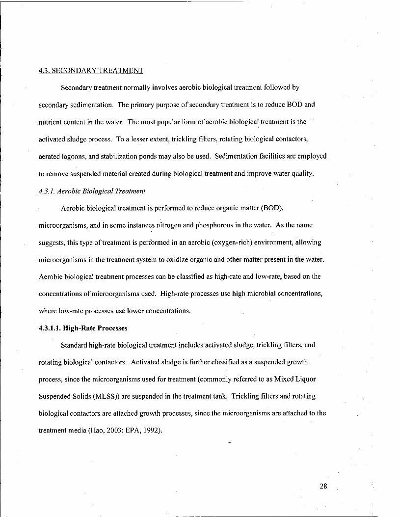
and wastewater (EPA, 1992; Noyes, 1980). Some trickling filter configurations are shown on
the following page:
29
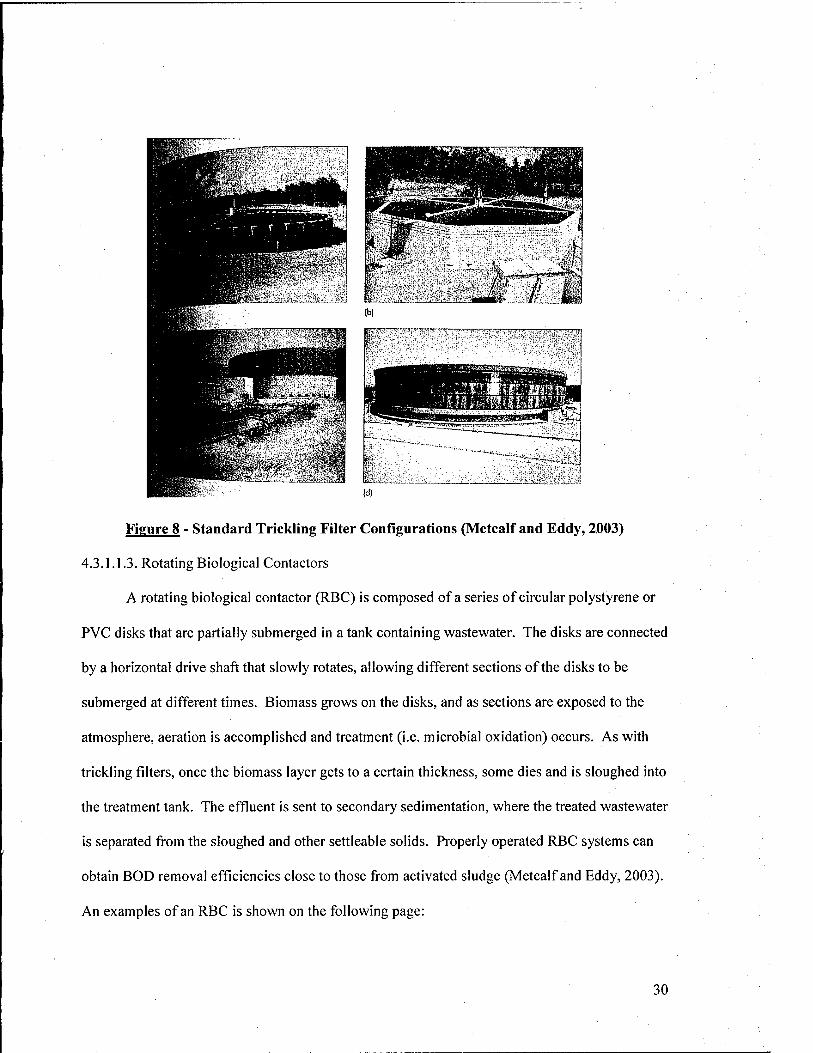
Figure 8 - Standard Trickling Filter Configurations (Metcalf and Eddy, 2003)
4.3.1.1.3. Rotating Biological Contactors
A rotating biological contactor (RBC) is composed of a series of circular polystyrene or
PVC disks that are partially submerged in a tank containing wastewater. The disks are connected
by a horizontal drive shaft that slowly rotates, allowing different sections of the disks to be
submerged at different times. Biomass grows on the disks, and as sections are exposed to the
atmosphere, aeration is accomplished and treatment (i.e. microbial oxidation) occurs. As with
trickh'ng filters, once the biomass layer gets to a certain thickness, some dies and is sloughed into
the treatment tank. The effluent is sent to secondary sedimentation, where the treated wastewater
is separated from the sloughed and other settleable solids. Properly operated RBC systems can
obtain BOD removal efficiencies close to those from activated sludge (Metcalf and Eddy, 2003).
An examples of an RBC is shown on the following page:
30
Figure 9 - Rotating Biological Contactor (Environmental Technology Centre, 2003)
4.3.1.2. Low-Rate Processes
4.3.1.2.1. Aerated Lagoons
Aerated lagoons are similar to the activated sludge process, in that they rely on suspended
growth to microorganisms in an aerobic environment to oxidize organic matter in the
wastewater. They are typically constructed of earthen materials and vary in depth from 1 to 5 m
(3 to 16 ft). Mechanical aerators are normally fixed on floats or platforms to provide aeration.
Effluent is then sent to earthen sedimentation basins or conventional clarifiers.
There are three primary types of aerated lagoons. They include facultative partially
mixed, aerobic flow through with partial mixing, and aerobic with solids recycle and nominal
complete mixing. The first type only provides enough aeration to perform wastewater treatment,
but not to keep all of the solids suspended. As a result, some settle into deeper, anaerobic
regions of the lagoon. These lagoons eventually become stratified with an aerobic layer on top,
anaerobic layer at bottom, and an intermediate zone in-between. They are referred to as
facultative lagoons, since biological degradation (treatment) occurs in both aerobic and anaerobic
environments. Due to the uncontrollable nature of facultative lagoons they have fallen out of
31
favor in recent years. In aerobic flow-through partially mixed lagoons, oxygen supplied is
enough to meet treatment requirements and maintain a completely aerobic environment, but not
sufficient to keep all solids in suspension. Finally, the aerobic lagoon with solids recycle is
essentially identical to the activated sludge process. The environment is entirely aerobic and
solids remain suspended. Further, a portion of the settled solids from the secondary
sedimentation process is recycled back to the head of the lagoon (Metcalf and Eddy, 2003;
USAGE, 1995).
4.3.1.2.2. Stabilization Ponds
Stabilization ponds are constructed in a similar manner to aerated lagoons. The primary
difference, however, is that stabilization ponds do not use mechanical aeration to provide oxygen
for biological treatment. Instead, they rely on oxygen produced from algae during
photosynthesis. They are also characterized by long residence times, typically on the order of 10
to 50 days. There are different types of stabilization ponds, which are typically built in series.
They include anaerobic or facultative oxidation ponds, high-rate ponds, algae settling ponds, and
maturation ponds. The first step in the treatment process involves removal of organic matter via
methanogenesis (methane formation). This is accomplished in an anaerobic environment,
typically at the bottom of an anaerobic or facultative oxidation pond. Influent wastewater is
discharged at the bottom of the pond to minimize dissolved oxygen intrusion and maintain an
anaerobic environment. Organic matter is transformed to methane gas via biological reduction.
In many cases, fermentation pits or in-pond digesters are located along the pond bottom to aid
this process. Anaerobic ponds maintain a strictly anaerobic environment, while facultative
oxidation ponds have three distinct layers (anaerobic, facultative, aerobic) as described in
Section 4.3.1.2.1 above. High-rate ponds (HRP) are utilized in the next step. They rely on
32
oxygen produced by algae to remove BOD from the water. In order to keep algae in suspension
and improve floe formation, paddle wheel mixers are normally installed in these ponds. Some
of the biomass produced in the HRP is recycled back to the anaerobic or facultative ponds to
increase removal efficiency. Once aerobic treatment is complete, some of the algae are removed
in algae settling ponds to maintain low effluent nutrient concentrations. Finally, aerobic
maturation ponds are used for effluent storage and to remove pathogens after biological
treatment. Stabilization pond systems have been shown to reduce BOD to 15-30 mg/L, SS to 15-
40 mg/L and 3-6 orders of magnitude for pathogens. They are also effective in removing
nitrogen, and to a lesser extent, phosphorous. However, chemical addition in the HRP stage is
often required to obtain acceptable removal efficiencies without any further treatment. (Green et
al., 1995; Nurdogan et al., 1995; EPA, 1992).
4.3.2. Secondary Sedimentation
Secondary sedimentation normally follows all aerobic biological treatment processes
described previously, and fiinctions in the same manner as primary sedimentation facilities.
During biological treatment, additional settleable solids are created and must be removed. BOD,
COD, some heavy metals, and organic compounds can be significantly reduced after biological
treatment and secondary sedimentation have occurred (EPA, 1992).
33
4.4. ADVANCED TREATMENT
Advanced treatment is a general treatment category involving high-efficiency and
specialized processes designed to reduce specific contaminants to extremely low levels in order
to meet permit or process requirements. The most common form of advanced treatment is
disinfection, which is employed by most domestic wastewater treatment plants before
discharging their effluent into surface water bodies. Advanced treatment processes can often be
expensive require considerable maintenance to ensure continued process efficiency. However,
they can produce very high quality effluents designed to be used in a myriad of applications.
Some of the most common forms of advanced treatment, specifically those employed in water
reuse projects, are described below.
4.4.1. Disinfection
The purpose of disinfection is to reduce pathogen concentrations to an acceptable level
(i.e. minimal risk to exposed individuals) in water used for reuse. While disinfection is not
technically an advanced treatment process, it is performed after secondary treatment, and
therefore can be considered separately. There are three primary types of disinfection processes
used today. They include chlorination, ozonation, and ultraviolet (UV) radiation. Chlorination
is by far the most popular method, due to its low cost and high effectiveness. Chlorine is added
to secondary effluent in the form of chlorine gas (CI2 (g), sodium hypochlorite (NaOCl), calcium
hypochlorite (Ca(0Cl)2), chlorine dioxide (CIO2), and in some case monochloramine (NH2CI).
The efficiency of disinfection and the chlorine dose required are dependent on water
temperature, pH, mixing, contact time, and presence of interfering substances (such as organics
and ammonia). A typical chlorine contact basin is pictured on the following page:
34
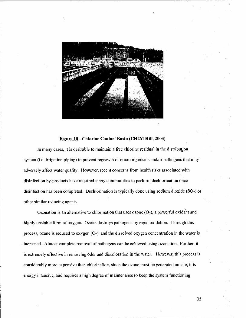
Figure 10 - Chlorine Contact Basin (CH2M Hill, 2003)
In many cases, it is desirable to maintain a free chlorine residual in the distribujjon
system (i.e. irrigation piping) to prevent regrowth of microorganisms and/or pathogens that may
adversely affect water quality. However, recent concerns from health risks associated with
disinfection by-products have required many communities to perform dechlorination once
disinfection has been completed. Dechlorination is typically done using sodium dioxide (SO2) or
other similar reducing agents.
Ozonation is an alternative to chlorination that uses ozone (O3), a powerful oxidant and
highly unstable form of oxygen. Ozone destroys pathogens by rapid oxidation. Through this
process, ozone is reduced to oxygen (O2), and the dissolved oxygen concentration in the water is
increased. Almost complete removal of pathogens can be achieved using ozonation. Further, it
is extremely effective in removing odor and discoloration in the water. However, this process is
considerably more expensive than chlorination, since the ozone must be generated on site, it is
energy intensive, and requires a high degree of maintenance to keep the system functioning
35
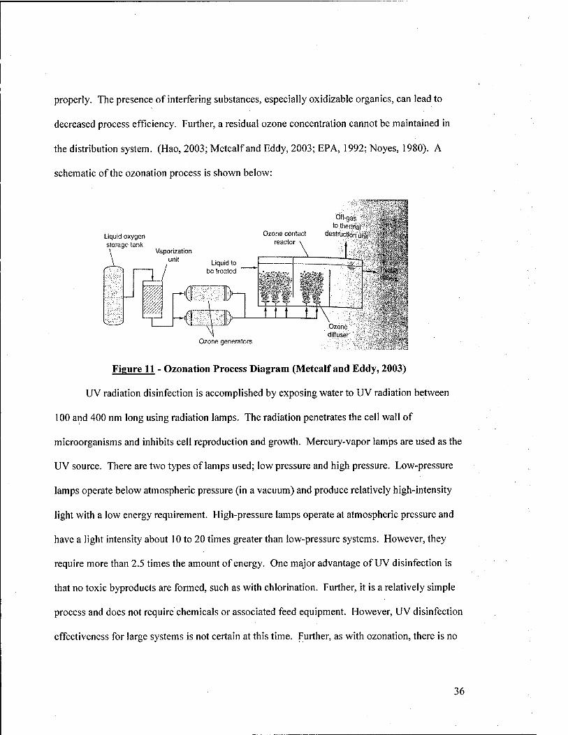
properly. The presence of interfering substances, especially oxidizable organics, can lead to
decreased process efficiency. Further, a residual ozone concentration cannot be maintained in
the distribution system. (Hao, 2003; Metcalf and Eddy, 2003; EPA, 1992; Noyes, 1980). A
schematic of the ozonation process is shown below:
Liquid oxygen storage tanl<
Vaporization unit Liquid to
be treated
m u ' ' D
cp
Off-gas to thermal
Ozone contact destruction utift reactor \ i
^W'Wi^'i
-^-T^ ^
t t t tf\
Pflimnl
Ozone generators
Ozone diffuser
Figure 11 - Ozonation Process Diagram (Metcalf and Eddy, 2003)
UV radiation disinfection is accomplished by exposing water to UV radiation between
100 and 400 nm long using radiation lamps. The radiation penetrates the cell wall of
microorganisms and inhibits cell reproduction and growth. Mercury-vapor lamps are used as the
UV source. There are two types of lamps used; low pressure and high pressure. Low-pressure
lamps operate below atmospheric pressure (in a vacuum) and produce relatively high-intensity
light with a low energy requirement. High-pressure lamps operate at atmospheric pressure and
have a light intensity about 10 to 20 times greater than low-pressure systems. However, they
require more than 2.5 times the amount of energy. One major advantage of UV disinfection is
that no toxic byproducts are formed, such as with chlorination. Further, it is a relatively simple
process and does not require chemicals or associated feed equipment. However, UV disinfection
effectiveness for large systems is not certain at this time. Further, as with ozonation, there is no
36
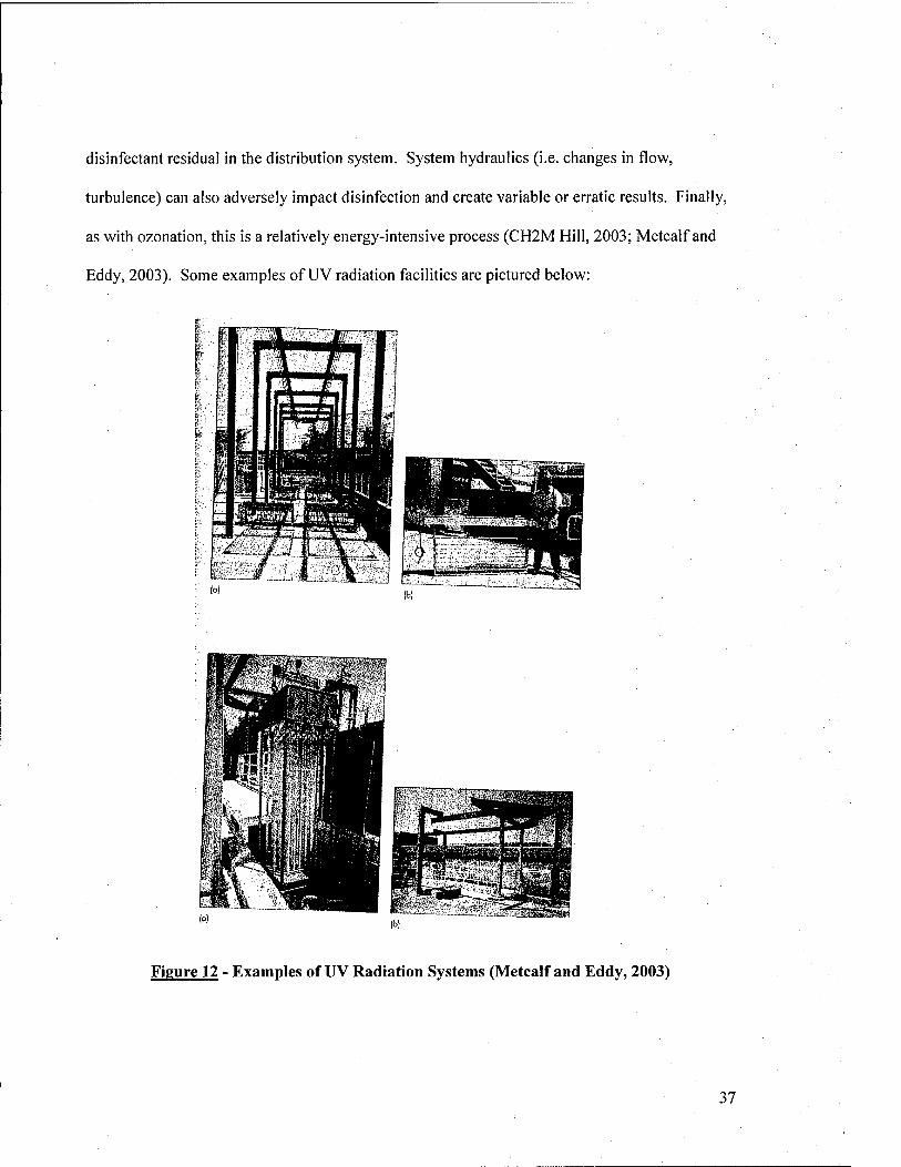
disinfectant residual in the distribution system. System hydraulics (i.e. changes in flow,
turbulence) can also adversely impact disinfection and create variable or erratic results. Finally,
as with ozonation, this is a relatively energy-intensive process (CH2M Hill, 2003; Metcalf and
Eddy, 2003). Some examples of UV radiation facilities are pictured below:
Figure 12 - Examples of UV Radiation Systems (Metcalf and Eddy, 2003)
37
4.4.2. Nitrification
Nitrification is the process of converting ammonia nitrogen (NH/) to nitrate nitrogen
(NO3') tlirougli biological oxidation. Due to the deleterious effects of ammonia nitrogen on
receiving waters and biota, it is often necessary to provide treatment involving nitrification. It is
important to note that the total nitrogen concentration is not reduced during nitrification, but only
its form is changed. Nitrification is normally performed using traditional suspended or attached
growth processes. The activated sludge system can be modified to incorporate nitrification. This
can be done in two ways. The first, and most common, is by increasing the residence time of the
water in the aeration tank. Nitrifying bacteria grow much slower than heterotrophic (carbon-
oxidizing) bacteria, and therefore require a much longer time to perform their function. If
traditional residence times are maintained, only BOD removal will be achieved, since the
heterotrophic bacteria will dominate. The second method involves a dual-stage activated sludge
process, whereby BOD removal and nitrification are achieved in different reactors. This process
essentially consists of two aeration tanks and two secondary clarifiers in series. The first
aeration tank has a shorter residence time for BOD removal, and the second has a longer one for
nitrification. Nitrification can occur in the second stage, since most of the BOD has already been
removed in the first stage.
Attached growth processes, such as rotating biological contactors and trickling filters can
also be used to achieve nitrification. In both cases, separate systems for BOD removal and
nitrification will have to be designed, since BOD removal dominates (as with single-stage
activated sludge) with only one reactor. As before, nitrification will occur in the second system
after BOD is removed (Hao, 2003; Metcalf and Eddy, 2003).
38
4.4.3. Denitrification
Denitrification is the biological reduction of nitrate nitrogen (NO3") to nitrate gas (N2 (g)).
Once nitrogen is converted to the gaseous form, it can escape into the atmosphere and reduce the
overall nitrogen concentration discharged into the environment. The most common methods of
denitrification involve modifications to suspended grov/th processes (i.e. activated sludge).
Denitrification requires an electron donor, which can come in the form of influent organic
matter, endogenous respiration, or an externally added carbon source (typically methanol).
Denitrification process units will either be constructed before or after biological aerobic
treatment facilities. They are further classified by the number of stages of sludge (solids)
removal that occur. In a single-stage system, all processes (BOD removal, nitrification,
denitrification) are completed before the effluent reaches a secondary clarifier. In multi-stage
sludge removal, secondary clarifiers are located after each process step. For denitrification that
occurs before aerobic biological treatment, the effluent from the aerobic processes is recycled to
the head of the denitrification unit. The effluent (which contains NOs') along with the influent
water provides the necessary conditions to promote denitrification. In addition, the tank is not
aerated in order to create an anoxic environment (absence of oxygen, presence of NOs'). For
systems where denitrification occurs after aerobic treatment, effluent from the aerobic processes
is sent directly to the denitrification unit. Denitrification occurs in the same manner as
previously described. Single stage sludge removal systems can employ either the pre- or post-
denitrification processes, since there is enough organic biomass in the unsettled effluent to act as
an electron donor. However, multi-stage sludge removal systems typically only employ the post-
denitrification system, since most of the biomass has been removed in previous steps. As such.
39
before the denitrification unit, organic carbon is added to facilitate the process (Hao, 2003;
Metcalf and Eddy, 2003).
Another option for denitrification is the use of deep bed denitrifying filters (DBDF).
These units utilize a packed bed filter to remove suspended solids and biological nitrogen.
Denitrifying bacteria grow on the filter media, which is provided with an external carbon source
as described for the multi-stage sludge removal systems. The media is composed of coarse,
high-density sand. Filter beds are normally overlain with a gravel underdrain system. Hydraulic
loading rates are typically 1 to 2 gpm/ft^, with backwash frequencies of 1 to 4 days. Effluent
nitrate concentrations have been measured at or near 1 mg/L, which is significantly below most
state and Federal standards. Another benefit to the DBDF technology, is that is can be used
solely for suspended solids removal by ceasing external carbon source addition. This may be
done during times of low reuse water demand to augment the existing treatment facilities (CH21VI
Hill, 2003).
4.4.4. Filtration
Filtration is typically performed after secondary biological treatment and before
disinfection. In recent years, it has become extremely popular in treatment of secondary
effluents and greywater, due to the significant additional contaminant removal that may be
achieved. There are two primary classes of filters that can be used for treatment of water for
reuse applications. They include manufactured and in-situ technologies. The former are
comprised of more conventional technologies used in drinking and wastewater treatment plants,
and are considered first. Conventional depth filters involve percolating a secondary effluent or
greywater through a granular media bed. The bed is typically contained in a filter column or
tank. Standard filtration rates range from 3-6 gpm/ft^. Solid material in the water is retained on
40
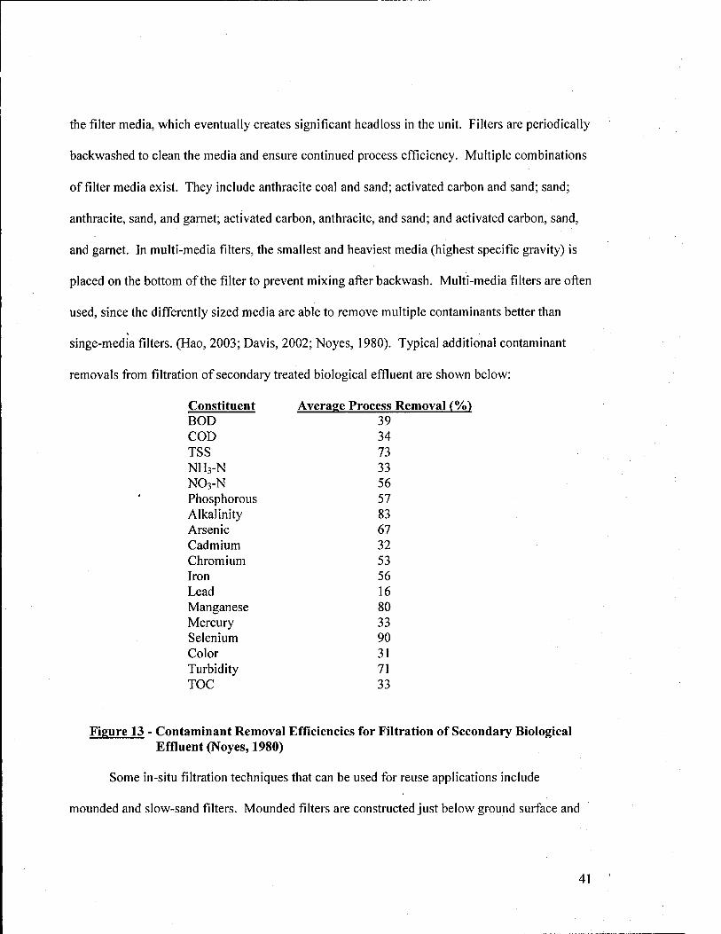
the filter media, which eventually creates significant headloss in the unit. Filters are periodically
backwashed to clean the media and ensure continued process efficiency. Multiple combinations
of filter media exist. They include anthracite coal and sand; activated carbon and sand; sand;
anthracite, sand, and garnet; activated carbon, anthracite, and sand; and activated carbon, sand,
and garnet. In multi-media filters, the smallest and heaviest media (highest specific gravity) is
placed on the bottom of the filter to prevent mixing after backwash. Multi-media filters are often
used, since the differently sized media are able to remove multiple contaminants better than
singe-media filters. (Hao, 2003; Davis, 2002; Noyes, 1980). Typical additional contaminant
removals from filtration of secondary treated biological effiuent are shown below:
Constituent Average Process Removal (%) BOD 39 COD 34 TSS 73 NH3-N 33 NO3-N 56 Phosphorous 57 Alkalinity 83 Arsenic 67 Cadmium 32 Chromium 53 Iron 56 Lead 16 Manganese 80 Mercury 33 Selenium 90 Color 31 Turbidity 71 TOC 33
Figure 13 - Contaminant Removal Efficiencies for Filtration of Secondary Biological Effluent (Noyes, 1980)
Some in-situ filtration techniques that can be used for reuse applications include
mounded and slow-sand filters. Mounded filters are constructed just below ground surface and
41
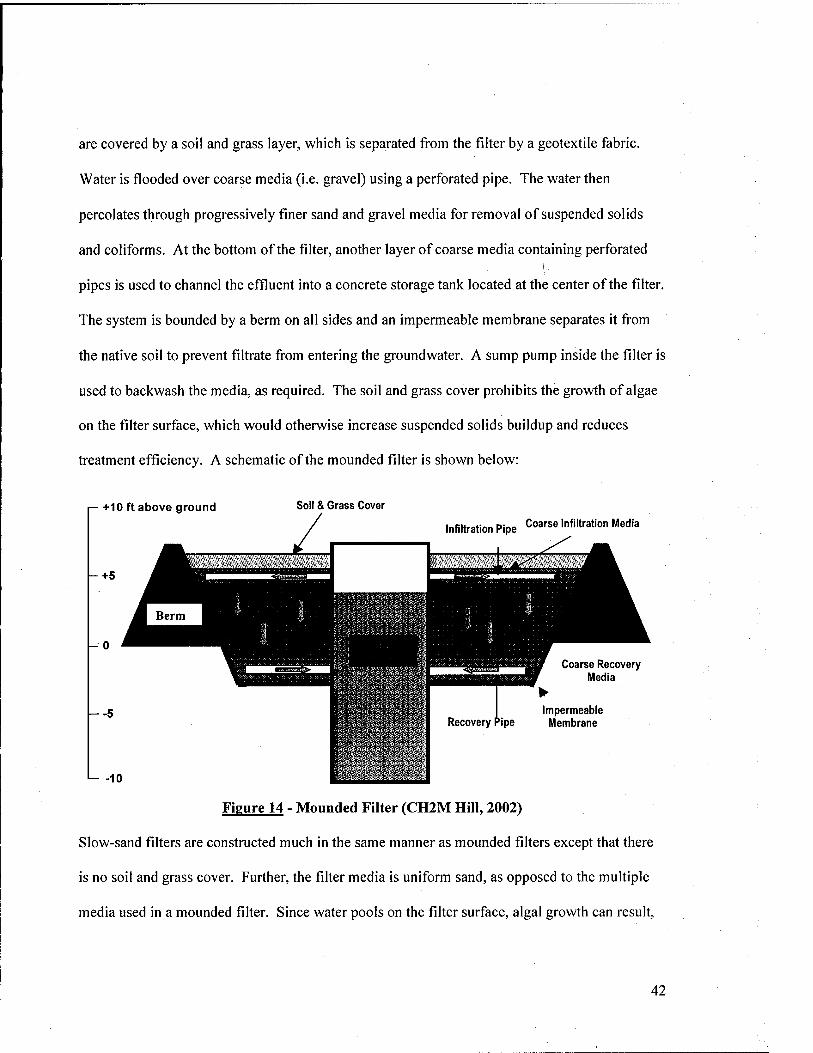
are covered by a soil and grass layer, which is separated from the filter by a geotextile fabric.
Water is flooded over coarse media (i.e. gravel) using a perforated pipe. The water then
percolates through progressively finer sand and gravel media for removal of suspended solids
and conforms. At the bottom of the filter, another layer of coarse media containing perforated
pipes is used to channel the effluent into a concrete storage tank located at the center of the filter.
The system is bounded by a berm on all sides and an impermeable membrane separates it from
the native soil to prevent filtrate from entering the groundwater. A sump pump inside the filter is
used to backwash the media, as required. The soil and grass cover prohibits the growth of algae
on the filter surface, which would otherwise increase suspended solids buildup and reduces
treatment efficiency. A schematic of the mounded filter is shown below:
+10 ft above ground Soil & Grass Cover
Infiltration Pipe Coarse Infiltration Media
Coarse Recovery Media
Impermeable Membrane
Figure 14 - Mounded Filter fCH2M Hill, 2002)
Slow-sand filters are constructed much in the same manner as mounded filters except that there
is no soil and grass cover. Further, the filter media is uniform sand, as opposed to the multiple
media used in a mounded filter. Since water pools on the filter surface, algal growth can result,
42
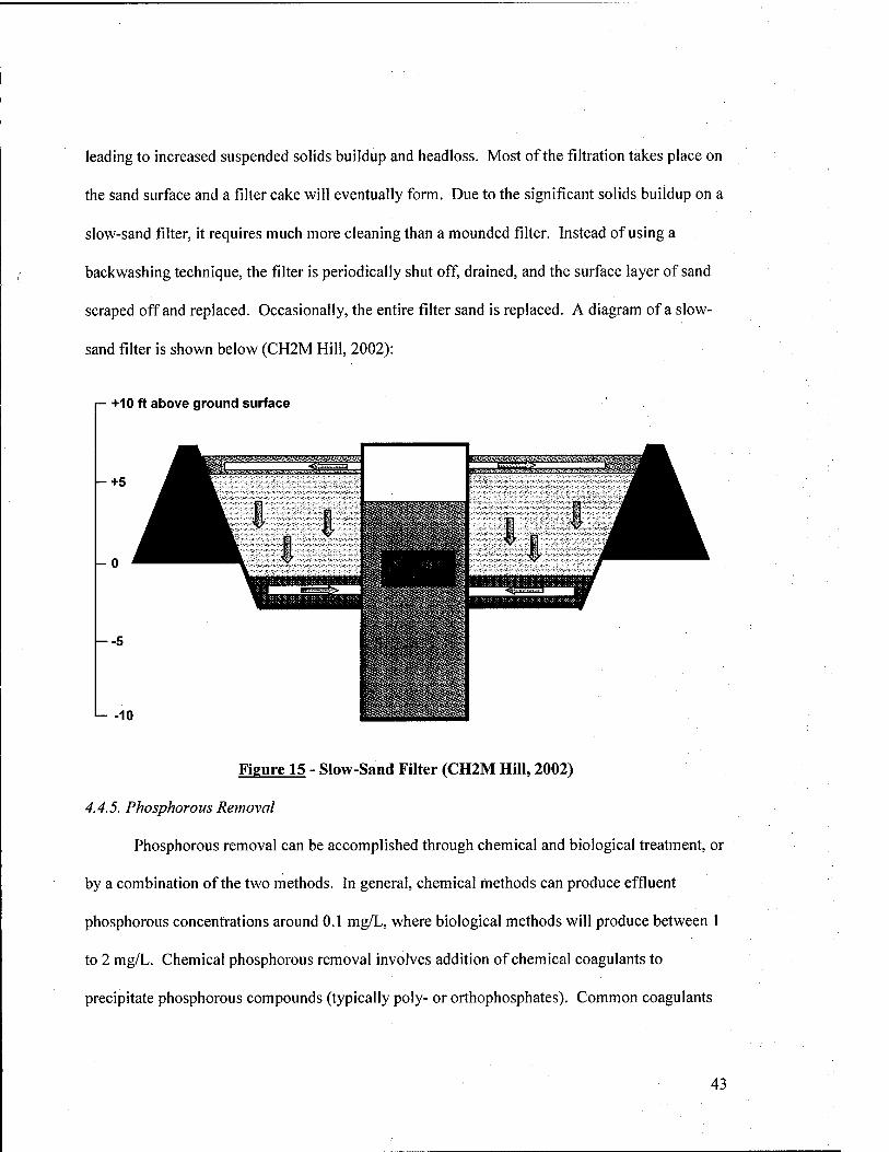
leading to increased suspended solids buildup and headloss. Most of the filtration takes place on
the sand surface and a filter cake will eventually form. Due to the significant solids buildup on a
slow-sand filter, it requires much more cleaning than a mounded filter. Instead of using a
backwashing technique, the filter is periodically shut off, drained, and the surface layer of sand
scraped off and replaced. Occasionally, the entire filter sand is replaced. A diagram of a slow-
sand filter is shown below (CH2M Hill, 2002):
+10 ft above ground surface
--5
-10
Figure 15 - Slow-Sand Filter (CH2M Hill, 2002)
4.4.5. Phosphorous Removal
Phosphorous removal can be accomplished through chemical and biological treatment, or
by a combination of the two methods. In general, chemical methods can produce effluent
phosphorous concentrations around 0.1 mg/L, where biological methods will produce between 1
to 2 mg/L. Chemical phosphorous removal involves addition of chemical coagulants to
precipitate phosphorous compounds (typically poly- or orthophosphates). Common coagulants
43
include lime (Ca(0H)2 or CaO), alum (Al2(S04)3-nH20), and ferric chloride (FeCls). Lime has
recently fallen out of favor, because of the large amounts of chemical sludge generated. As a
result, metal salts (alum and ferric chloride) tend to be more popular. Phosphorous precipitation
can occur at various points in the treatment process. Pre-precipitation involves addition of
chemicals to wastewater as it enters primary sedimentation facilities. The precipitated
phosphorous is then removed as part of the primary sludge., Co-precipitation occurs when
phosphorus compounds are removed along with biomass solids generated during aerobic
biological treatment. In this case, chemicals are added after primary sedimentation, directly to
the aerobic reactor (i.e. activated sludge), or before secondary sedimentation. Finally, in post-
precipitation, chemicals are added after secondary sedimentation. Here, separate facilities are
constructed to coagulate and remove phosphorous. The latter option typically produces the best
results, since poly-phosphorous and organic phosphorous are much more difficult to remove than
ortho-phosphorous. During biological treatment, most of the phosphorous is converted to the
ortho-form. As such, when post-precipitation is employed, the maximum phosphorous removal
is obtained. Post-precipitation is usually conducted using a coagulation/flocculation/
sedimentation treatment scheme, often followed by fiUration (Metcalf and Eddy, 2003; EPA,
1992). This process is discussed in detail in Section 4.4.6.
Biological phosphorous removal operates by cuhivating^cwe/o6ac/er(phosphorous
accumulating organisms (PAO)), which uptake and store phosphorous under aerobic conditions
and release it under anaerobic conditions. It is normally performed using suspended growth
processes (i.e. activated sludge) with alternating anaerobic, aerobic, and/or anoxic zones. A
number of processes have been developed for biological process removal. They include
44
anaerobic/aerobic only (A/0), anaerobic/anoxic/aerobic (A^/0), Photostrip™^, and the Modified
Bardenpho 5-Stage process.
The A/0 process an anaerobic zone is followed by an aerobic zone, which allows for the
uptake of phosphorous by the MLSS. The effluent is sent to a clarifier, where the phosphorous is
removed along with the settleable solids. Some of the sludge from the clarifier is recycled back
to the head of the process to maintain the biomass concentration in the reactors.
The AVO process uses the same basic concept as A/0, except that an anoxic zone is
added after the anaerobic zone for denitrification. Effluent from the aerobic zone is recycled to
the head of the anoxic zone to provide nitrate nitrogen (NO3"). The anoxic zone also serves to
minimize the amount of nitrate nitrogen in the recycled sludge sent to the anaerobic zone. This
improves phosphorous removal, since heterotrophic bacteria use nitrate nitrogen to consume
organics in the anaerobic zone, leaving less "food" for the PAO.
The Photostrip^^ process uses a combination of chemical and biological means to
remove phosphorous. Water enters and aerobic zone, where phosphorus uptake occurs. The
effluent is sent to a clarifier, where a portion of the settled sludge is sent to an anaerobic tank.
Since the sludge has a high phosphorous content and anaerobic conditions exist, the phosphorous
is released into solution. Some settled solids from the anaerobic tank are returned to the aerobic
process, while lime is added to the supernatant to chemically precipitate the phosphorous.
Finally, the Modified Bardenpho 5-Stage process incorporates an anaerobic tank,
followed by an anoxic tank, aerobic tank, anoxic tank, and finally another aerobic tank. This is a
single-stage activated sludge process, similar to that described in Section 4.4.3, where the
effluent from the final aerobic tank is sent to a clarifier. A portion of the settled solids is
recycled back to the head of the process to maintain the MLSS concentration. This process
45
provides for staged nitrogen, phosphorous, and carbon (BOD) removal. In the anaerobic stage,
phosphorous is released into solution. The first anoxic stage is used to denitrify nitrate nitrogen
that is recycled in from the proceeding aerobic stage. As previously stated, the anoxic stage
helps to improve phosphorous removal efficiency. Phosphorous uptake occurs in the aerobic
stage, along with nitrification and BOD removal. Endogenous respiration (using nitrate
nitrogen) for denitrification occurs in the second anoxic stage to provide additional nitrogen
removal. Finally, in the second aerobic stage, remaining nitrogen gas is stripped from the water
and dissolved oxygen concentration is increased in the effluent The solids removed from the
clarifier have a high phosphorous concentration (Hao, 2003; Metcalf and Eddy, 2003; EPA,
1992).
4.4.6. Coagulation/Flocculation/Sedimentation
The coagulation-flocculation-sedimentation process is performed to remove colloidal
particles in the effluent from secondary or other advanced treatment processes. Coagulants such
as lime (Ca(0H)2 or CaO), alum (Al2(S04)3-nH20), and ferric chloride (FeCls) are used to
destabilize particles in solution by reducing the thickness of the electrical double layer that
surrounds them. This allows attractive forces between the particles to dominate causing them to
"stick" together and form larger particles (called floes). Eventually the floes get large enough
that they settle out of solution, allowing them to be removed by sedimentation (Davis, 2002).
Coagulants are available in both wet and dry form and must be blended to the appropriate
strength using a chemical feed system. The first step in the process is termed rapid mixing.'
Here, chemicals from the feed system are blended with the water in a small tank with about a 30-
second retention time. Baffles are often installed in the tank to improve mixing efficiency. The
rapid mix tank is normally located directly adjacent to a flocculation basin, which is a slow mix
46
tank (or series of tanks) used to promote floe formation. The flocculation tank contains a series
of mixers, which gently agitate the water. Three basic types of flocculation mixers exist
including static, turbines/propellers, and paddles. Static mixers are impediments placed in the
tank (i.e. baffles) causing flow direction to be changed or reversed. Turbine or propeller mixers
use a rotating vertical or horizontal shaft with three or four blades attached. Paddle mixers are
constructed of a series of vertically or horizontally mounted paddles attached to a central drive
shaft. Many wastewater treatment plants employ a combination of paddle mixers with baffles to
prevent short-circuiting of the flocculation process by the wastewater. The type of mixer used
often depends on the contaminants being removed and type of coagulants. Further, flocculation
basins can be either single- or multi-stage. For example, phosphorous removal is best
accomplished through staged flocculation. In multi-stage flocculation, baffles normally separate
the units and the velocity gradient is reduced in each successive basin. This allows for
progressively larger particles to be formed as the wastewater travels through each basin.
Variable drive speed shafts or changing the size and/or number of paddles will cause the velocity
gradients to change. Once flocculation is complete, the water is sent to a sedimentation basin to
remove the settled particles (Hao, 2003; Metcalf and Eddy, 2003; Envirex, 1989). Typical
removal efficiencies using various types of coagulants are shown on the following page:
47
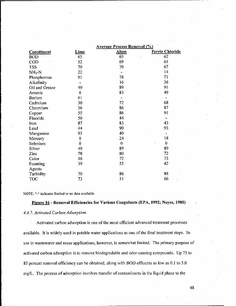
Average Process Removal (Vo) Constituent Lime Alum Ferric Chloride BOD 65 65 62 COD 52 69 61 TSS 70 70 67 NH3-N 22 - 14 Phosphorous 91 78 71 Alkalinity - 16 36 Oil and Grease 40 89 91 Arsenic 6 83 49 Barium 61 - -
Cadmium 30 72 68 Chromium 56 86 87 Copper 55 86 91 Fluoride 50 44 -
Iron 87 83 43 Lead 44 90 93 Manganese 93 40 -
Mercury 0 24 18 Selenium 0 0 0 Silver 49 89 89 Zinc 78 80 72 Color 46 72 73 Foaming 39 55 42 Agents Turbidity 70 86 88 TOC 73 51 66
NOTE: "-" indicates limited or no data available.
Figure 16 - Removal Efficiencies for Various Coagulants (EPA, 1992; Noyes, 1980)
4.4.7. A ctivated Carbon A dsorption
Activated carbon adsorption is one of the most efficient advanced treatment processes
available. It is widely used in potable water applications as one of the final treatment steps. Its
use in wastewater and reuse applications, however, is somewhat limited. The primary purpose of
activated carbon adsorption is to remove biodegradable and odor-causing compounds. Up 75 to
85 percent removal efficiency can be obtained, along with BOD effluents as low as 0.1 to 5.0
mg/L. The process of adsorption involves transfer of contaminants in the liquid phase to the
48
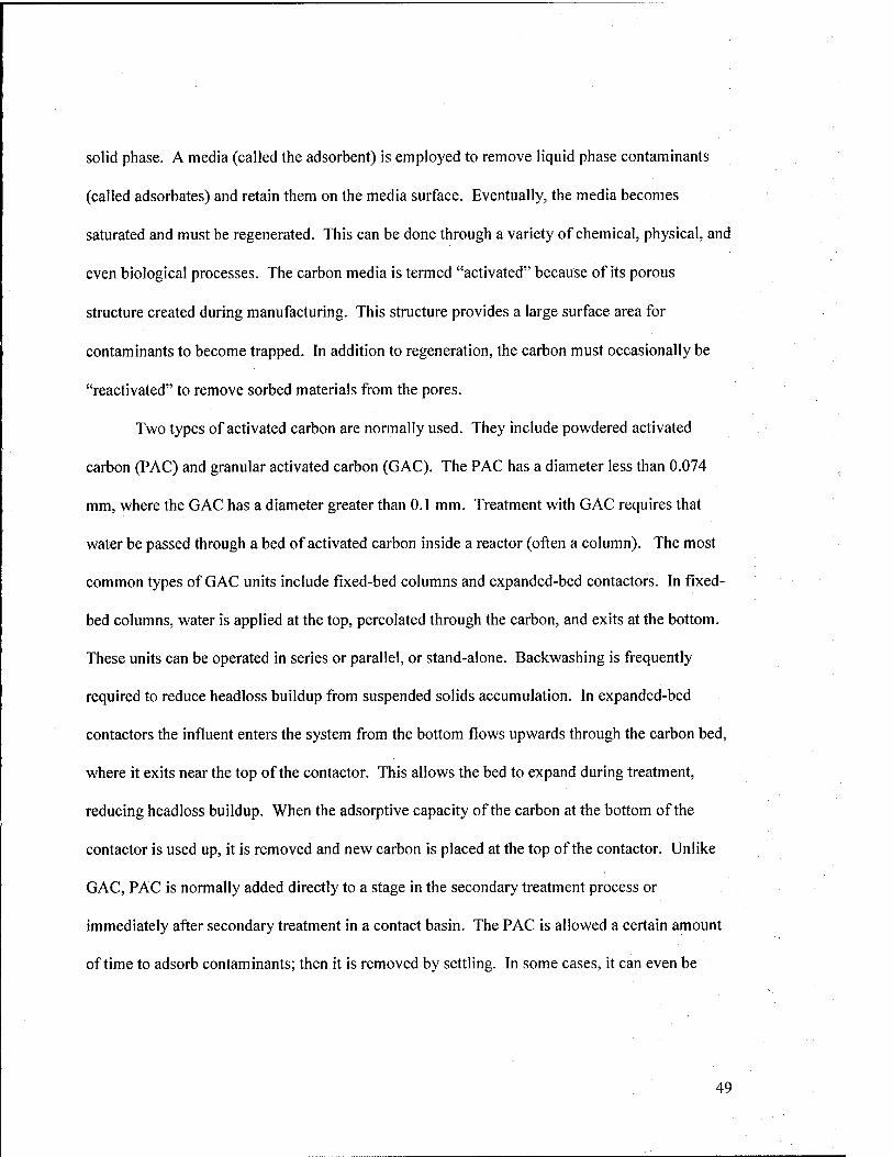
solid phase. A media (called the adsorbent) is employed to remove liquid phase contaminants
(called adsorbates) and retain them on the media surface. Eventually, the media becomes
saturated and must be regenerated. This can be done through a variety of chemical, physical, and
even biological processes. The carbon media is termed "activated" because of its porous
structure created during manufacturing. This structure provides a large surface area for
contaminants to become trapped. In addition to regeneration, the carbon must occasionally be
"reactivated" to remove sorbed materials from the pores.
Two types of activated carbon are normally used. They include powdered activated
carbon (PAC) and granular activated carbon (GAC). The PAC has a diameter less than 0.074
mm, where the GAC has a diameter greater than 0.1 mm. Treatment with GAC requires that
water be passed through a bed of activated carbon inside a reactor (often a column). The most
common types of GAC units include fixed-bed columns and expanded-bed contactors. In fixed-
bed columns, water is applied at the top, percolated through the carbon, and exits at the bottom.
These units can be operated in series or parallel, or stand-alone. Backwashing is frequently
required to reduce headloss buildup from suspended solids accumulation. In expanded-bed
contactors the influent enters the system from the bottom flows upwards through the carbon bed,
where it exits near the top of the contactor. This allows the bed to expand during treatment,
reducing headloss buildup. When the adsorptive capacity of the carbon at the bottom of the
contactor is used up, it is removed and new carbon is placed at the top of the contactor. Unlike
GAC, PAC is normally added directly to a stage in the secondary treatment process or
immediately after secondary treatment in a contact basin. The PAC is allowed a certain amount
of time to adsorb contaminants; then it is removed by settling. In some cases, it can even be
49
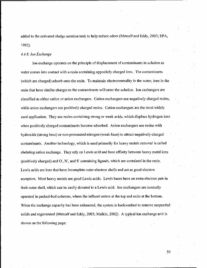
added to the activated sludge aeration tank to help reduce odors (Metcalf and Eddy, 2003; EPA,
1992).
4.4.8. Ion Exchange
Ion exchange operates on the principle of displacement of contaminants in solution as
water comes into contact with a resin containing oppositely charged ions. The contaminants
(which are charged) adsorb onto the resin. To maintain electroneutrality in the water, ions in the
resin that have similar charges to the contaminants will enter the solution. Ion exchangers are
classified as either cation or anion exchangers. Cation exchangers use negatively charged resins,
while anion exchangers use positively charged resins. Cation exchangers are the most widely
used application. They use resins containing strong or weak acids, which displace hydrogen ions
when positively charged contaminants become adsorbed. Anion exchangers use resins with
hydroxide (strong base) or non-protonated nitrogen (weak-base) to attract negatively charged
contaminants. Another technology, which is used primarily for heavy metals removal is called
chelating cation exchange. They rely on Lewis acid and base affinity between heavy metal ions
(positively charged) and O', N', and S" containing ligands, which are contained in the resin.
Lewis acids are ions that have incomplete outer electron shells and act as good electron
acceptors. Most heavy metals are good Lewis acids. Lewis bases have an extra electron pair in
their outer shell, which can be easily donated to a Lewis acid. Ion exchangers are normally
operated in packed-bed columns, where the influent enters at the top and exits at the bottom.
When the exchange capacity has been exhausted, the system is backwashed to remove suspended
solids and regenerated (Metcalf and Eddy, 2003; Malkin, 2002). A typical ion exchange unit is
shown on the following page:
50
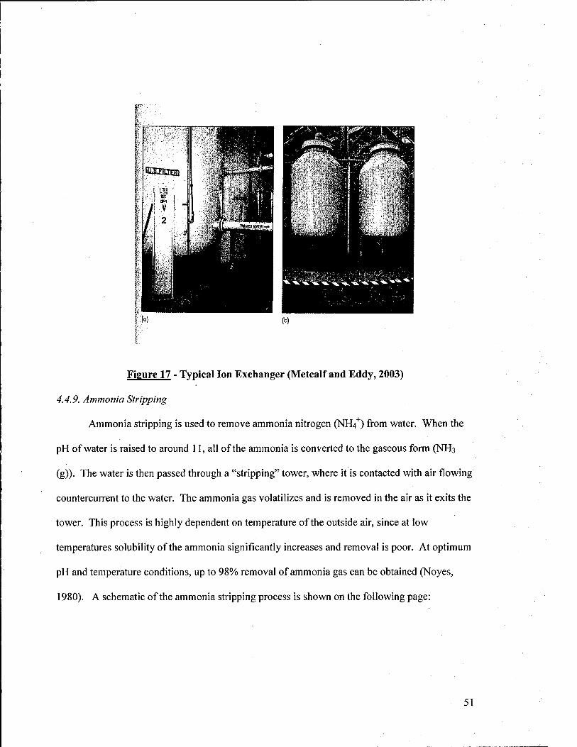
Figure 17 - Typical Ion Exchanger (Metcalf and Eddy, 2003)
4.4.9. Ammonia Stripping
Ammonia stripping is used to remove ammonia nitrogen (NH4"^) from water. When the
pH of water is raised to around 11, all of the ammonia is converted to the gaseous form (NH3
(g)). The water is then passed through a "stripping" tower, where it is contacted with air flowing
countercurrent to the water. The ammonia gas volatilizes and is removed in the air as it exits the
tower. This process is highly dependent on temperature of the outside air, since at low
temperatures solubility of the ammonia significantly increases and removal is poor. At optimum
pH and temperature conditions, up to 98% removal of ammonia gas can be obtained (Noyes,
1980). A schematic of the ammonia stripping process is shown on the following page:
51
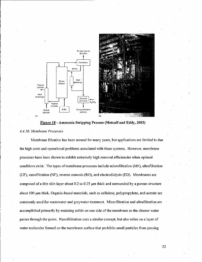
To odof control absorber
Treated cenlraie
Heat exchanger
Stenm striprjer
Treated centrale
Seliled centrale
I Heat
exchanger
Aqueous ammonia
HjSO.
Boiter To cr>'sta!!rzaIiDn process
(a)
Figure 18 - Ammonia Stripping Process (Metcalf and Eddy, 2003)
4.4.10. Membrane Processes
Membrane filtration has been around for many years, but applications are limited to due
the high costs and operational problems associated with these systems. However, membrane
processes have been shown to exhibit extremely high removal efficiencies when optimal
conditions exist. The types of membrane processes include microfiltration (MF), ultrafiltration
(UF), nanofiltration (NF), reverse osmosis (RO), and electrodialysis (ED). Membranes are
composed of a thin skin layer about 0.2 to 0.25 |am thick and surrounded by a porous structure
about 100 )u.m thick. Organic-based materials, such as cellulose, polypropylene, and acetate are
commonly used for wastewater and greywater treatment. Microfiltration and ultrafiltration are
accomplished primarily by retaining solids on one side of the membrane as the cleaner water
passes through the pores. Nanofilitration uses a similar concept, but also relies on a layer of
water molecules formed on the membrane surface that prohibits small particles from passing
52
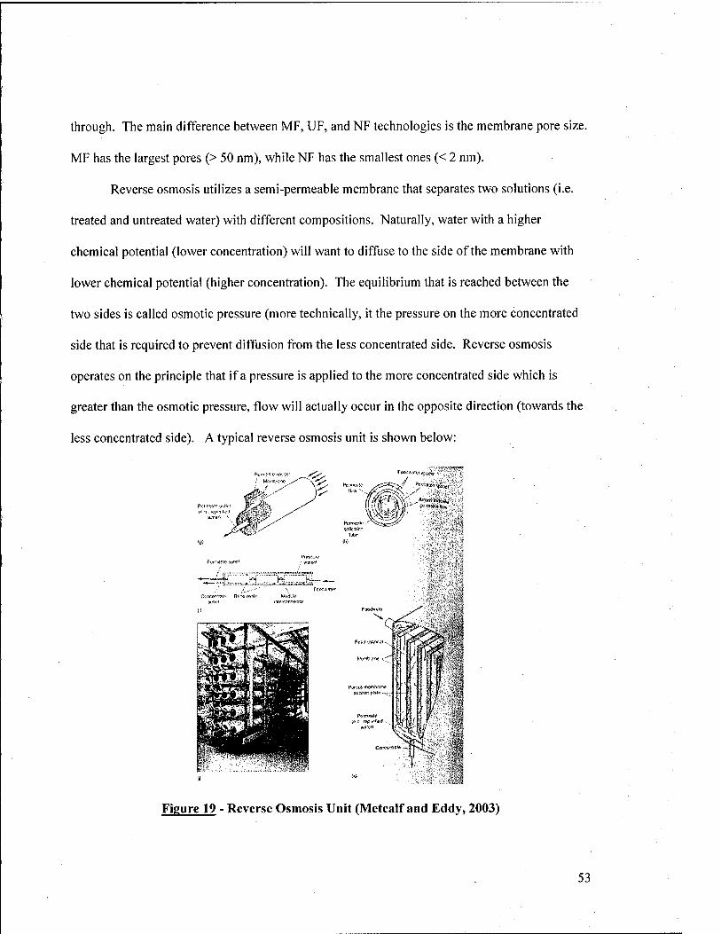
through. The main difference between MF, UF, and NF technologies is the membrane pore size.
MF has the largest pores (> 50 nm), while NF has the smallest ones (< 2 nm).
Reverse osmosis utilizes a semi-permeable membrane that separates two solutions (i.e.
treated and untreated water) with different compositions. Naturally, water with a higher
chemical potential (lower concentration) will want to diffuse to the side of the membrane with
lower chemical potential (higher concentration). The equilibrium that is reached between the
two sides is called osmotic pressure (more technically, it the pressure on the more concentrated
side that is required to prevent diffusion from the less concentrated side. Reverse osmosis
operates on the principle that if a pressure is applied to the more concentrated side which is
greater than the osmotic pressure, flow will actually occur in the opposite direction (towards the
less concentrated side). A typical reverse osmosis unit is shown below:
y Mrfiiji.:--
Pi-lin-Ki'f wP'I #fe im- ^>^<6>'
Pwi O'-'c >j!ic vf-s^
W^ to
, 5
Figure 19 - Reverse Osmosis Unit (Metcalf and Eddy, 2003)
53
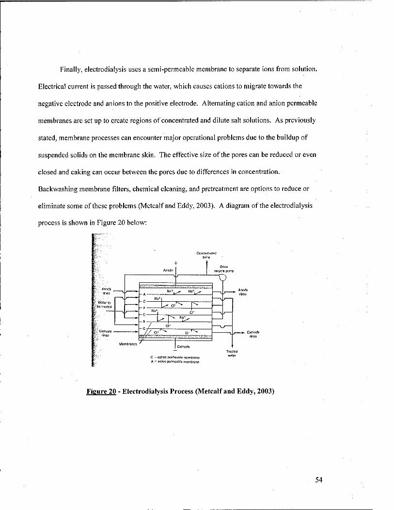
Finally, electrodialysis uses a semi-permeable membrane to separate ions from solution.
Electrical current is passed through the water, which causes cations to migrate towards the
negative electrode and anions to the positive electrode. Alternating cation and anion permeable
membranes are set up to create regions of concentrated and dilute salt solutions. As previously
stated, membrane processes can encounter major operational problems due to the buildup of
suspended solids on the membrane skin. The effective size of the pores can be reduced or even
closed and caking can occur between the pores due to differences in concentration.
Backwashing membrane filters, chemical cleaning, and pretreatment are options to reduce or
eliminate some of these problems (Metcalf and Eddy, 2003). A diagram of the electrodialysis
process is shown in Figure 20 below:
Anode rtnse
Waler to be ireated
Calhode • nnse
Concentrated brine
"u^ "°"i^
T'^^
T ^X^
^T7 f^ T"=^
C " catfon pcrmeaWe membrane A - anion permeable membrane
Brine recycle pump
T) Anode rinse
Caihotffe rinse
Treaied water
Figure 20 - Electrodialysis Process (Metcalf and Eddy, 2003)
54
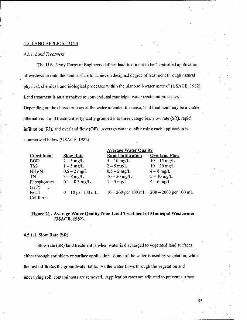
4.5. LAND APPLICATIONS
4.5.1. Land Treatment
The U.S. Army Corps of Engineers defines land treatment to be "controlled application
of wastewater onto the land surface to achieve a designed degree of treatment through natural
physical, chemical, and biological processes within the plant-soil-water matrix" (USACE, 1982).
Land treatment is an alternative to conventional municipal water treatment processes.
Depending on the characteristics of the water intended for reuse, land treatment may be a viable
alternative. Land treatment is typically grouped into three categories; slow rate (SR), rapid
infiltration (Rl), and overland flow (OF). Average water quality using each application is
summarized below (USACE, 1982):
Average Water Quality Rapid Infiltration Overland Flovy 5-lOmg/L 10-15mg/L 2-5mg/L 10-20mg/L 0.5-2mg/L 4-8mg/L 10-20 mg/L 5-lOmg/L 1 - 5 mg/L 4-6 mg/L
10-200 per 100 mL 200-2000 per 100 mL
Figure 21 - Average Water Quality from Land Treatment of Municipal Wastewater (USACE, 1982)
4.5.1.1. Slow Rate (SR)
Slow rate (SR) land treatment is when water is discharged to vegetated land surfaces
either through sprinklers or surface application. Some of the water is used by vegetation, while
the rest infiltrates the groundwater table. As the water flows through the vegetation and
underlying soil, contaminants are removed. Application rates are adjusted to prevent surface
55
Constituent Slow Rate BOD 2-5 mg/L TSS 1 - 5 mg/L NH3-N 0.5 - 2 mg/L TN 3-8 mg/L Phosphorous 0.1-0.3 mg/L (as P) Fecal 0-10 per 100 Conforms
runoff. A major advantage of SR systems is that they replace the need to use potable water for
irrigation. As such, substantial water use reductions can be implemented for agricultural land,
grassy areas, golf courses, parks, and other areas requiring large amounts of water. The major
disadvantage of SR systems is that they often do not produce BOD and nutrient removals high
enough to meet EPA or state drinking water regulations for ground water quality. Nitrogen
removal is often the primary concern, since many states have strict limits for nitrogen discharge
to groundwater. Sufficient nitrogen removal cannot normally be obtained through SR treatment,
and consequently either the hydraulic loading of reclaimed water must be curtailed or this option
is disregarded entirely for fear of non-compliance (USAGE, 1982).
4.5.1.2. Rapid Infiltration (RI)
Rapid infiltration (RI) involves the use of surface basins to collect and distribute water
through moderately or highly permeable soils. As in SR treatment, contaminants are removed as
the water percolates through the ground. RI differs from SR treatment in that most of the water
percolates to the groundwater table and there is little use by plants. In fact, most areas where RI
systems are employed have little or no vegetative cover. Further, water in the basins will often
drain naturally to nearby surface water bodies. This method is often used for groundwater
recharge applications or if storage of water in temporary aquifers, wells, or underdrains is desired
for later use.
A potential application for non-potable water reuse involves creation of a man-made
aquifer to treat and store water for later use. One method developed by CH2M Hill involves
percolating secondary effluent through a soil matrix into a shallow aquifer. A buried perforated
pipe is used for extracting water from the aquifer, which is then stored in a tank for use as
irrigation water. The type of native soil, location (relative depth) of other aquifers, and treatment
56
efficiency are major factors to be considered when implementing Rl systems. Nitrogen removal
is often a limiting factor, similar to SR systems. Successful implementation strongly relies on
the quality of the influent, regulatory limits, and site stratigraphy (CH2M Hill, 2002; USAGE,
1982).
4.5.1.3. Overland Flow (OF)
In overland flow (OF) water is introduced at the top of a vegetated sloped surface via
pipes or surface trenches and allowed to flow into runoff collection ditches in lower-lying areas.
Once water is collected, it may be recycled through the system again, discharged to surface water
bodies, or used for land application. Unlike SR and RI systems, impermeable soils are best for
this type of treatment, since contaminant removal occurs as the water passes over land, instead of
through the soil matrix. This process is also effective in moderately permeable soils with
impermeable underlying strata (MDE, 2002; USAGE, 1982).
4.5.2. Constructed Wetlands
Gonstructed wetlands are a natural treatment process using man-made wetlands at
locations where naturally occurring wetlands did not previously exist. Since they are considered
a treatment process and not a "receiving water" under the Glean Water Act, they are exempt
from related discharge regulations. Water flows into the wetland and is naturally treated by biota
(mainly indigenous wetland plants) to remove contaminants. Plants filter contaminants and
provide a growth surface for bacteria, while the root zone facilitates oxidation of organic
material, since it is an aerobic environment. Two primary types of constructed wetlands exist.
They are termed surface flow (SF) and subsurface flow (SSF). In SF systems, aquatic vegetation
grows above the water surface in a shallow bed or channel. As water flows through the wetland
it is exposed to the atmosphere. In a SSF system, vegetation grows in a permeable stratum such
57

as rock, gravel, sand, or soil. Water flows underground, just below the surface. Constructed
wetlands can often provide up to 80% removal of BOD, suspended solids, phosphorous, trace
heavy metals, and other trace organic compounds (USAGE, 1995).
58
5. INDUSTRIAL USES
Industrial water use accounts for a significant fraction of potable water consumption on
U.S. Navy Bases. WJiile not all applications lend themselves to water reuse, many of them do.
This section considers the most likely processes where water reuse initiatives can be
implemented with little or no impact on operational effectiveness. Industrial applications
considered include: (1) Vehicle and Aircraft Washing Facilities, (2) Plating Operations, (3)
Metal Cleaning Facilities, (4) Industrial Laundry Facilities, and (5) Cooling Systems
5.1. VEHICLE AND AIRCRAFT WASHING FACILITIES
The Navy maintains over 1,200 washrack facilities for cleaning of tactical/tracked
vehicles, automobiles, and aircraft. They are generally categorized as follows:
Aircraft Washrack Pavement
Aircraft Rinsing Facility
Aircraft Fire and Rescue Station
Combined Structural/Aircraft Fire and Rescue Station
Landing Craft Washrack
Amphibian Vehicle Maintenance Shop
Combat Vehicle Maintenance Shop
Automotive Vehicle Maintenance Shop
Vehicle Washing Platform
These facilities are further classified by the quality and composition of washwater effluent.
Characteristics of each type of facility are shown on the following page:
59
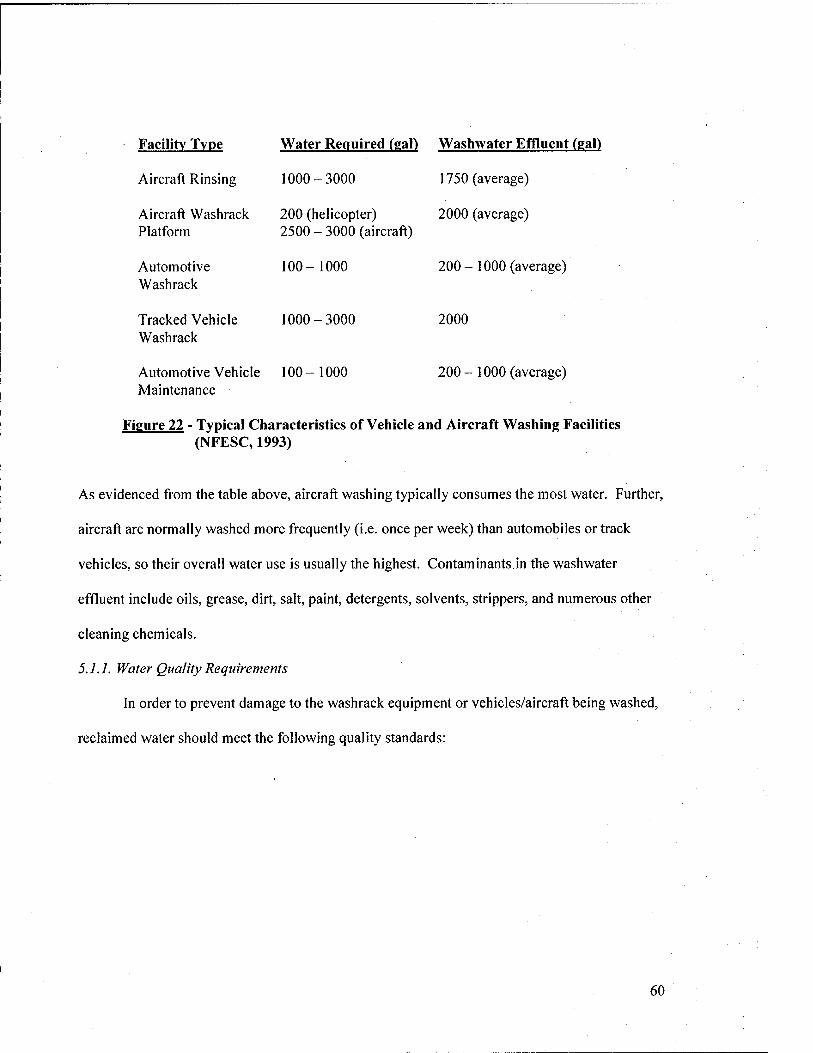
Facility Type Water Required (gal) Washwater Effluent (gal)
Aircraft Rinsing 1000-3000 1750 (average)
Aircraft Washrack 200 (helicopter) 2000 (average) Platform 2500 - 3000 (aircraft)
Automotive 100-1000 200-1000 (average) Washrack
Tracked Vehicle 1000-3000 2000 Washrack
Automotive Vehicle 100-1000 200-1000 (average) Maintenance
Figure 22 - Typical Characteristics of Vehicle and Aircraft Washing Facilities (NFESC, 1993)
As evidenced fi-om the table above, aircraft washing typically consumes the most water. Further,
aircraft are normally washed more frequently (i.e. once per week) than automobiles or track
vehicles, so their overall water use is usually the highest. Contaminants in the washwater
effluent include oils, grease, dirt, salt, paint, detergents, solvents, strippers, and numerous other
cleaning chemicals.
5.1.1. Water Quality Requirements
In order to prevent damage to the washrack equipment or vehicles/aircraft being washed,
reclaimed water should meet the following quality standards:
60
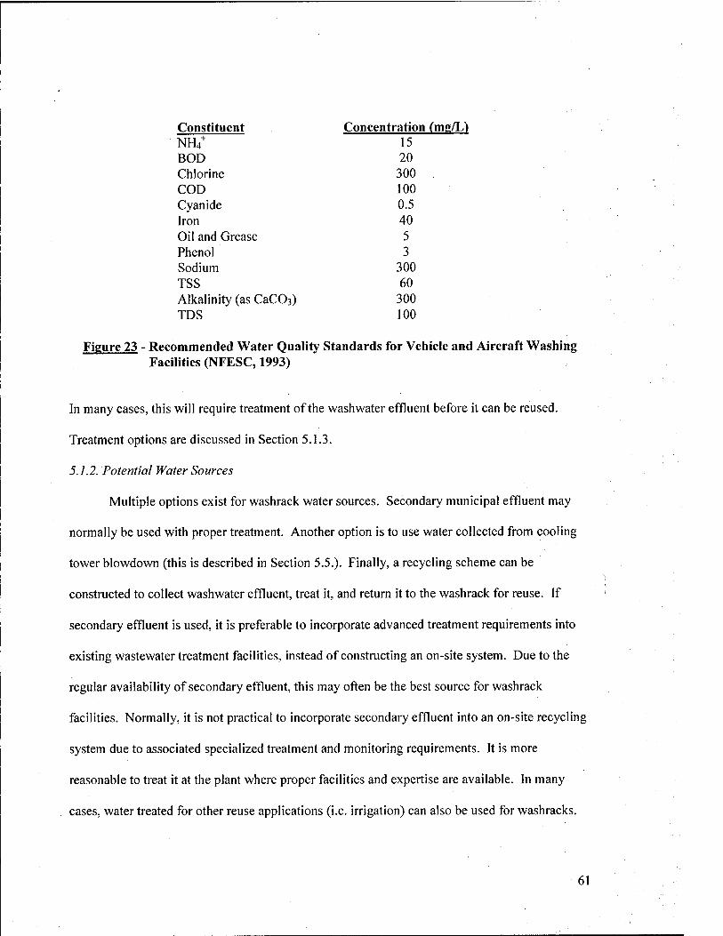
Constituent Concentration (mg/L) NH/ 15 BOD 20 Chlorine 300 COD 100 Cyanide 0.5 Iron 40 Oil and Grease 5 Phenol 3 Sodium 300 TSS 60 Alkalinity (as CaCOs) 300 TDS 100
Figure 23 - Recommended Water Quality Standards for Vehicle and Aircraft Washing Facilities (NFESC, 1993)
In many cases, this will require treatment of the washwater effluent before it can be reused.
Treatment options are discussed in Section 5.1.3.
5.1.2. Potential Water Sources
Multiple options exist for washrack water sources. Secondary municipal effluent may
normally be used with proper treatment. Another option is to use water collected from cooling
tower blowdown (this is described in Section 5.5.). Finally, a recycling scheme can be
constructed to collect washwater effluent, treat it, and return it to the washrack for reuse. If
secondary effluent is used, it is preferable to incorporate advanced treatment requirements into
existing wastewater treatment facilities, instead of constructing an on-site system. Due to the
regular availability of secondary effluent, this may often be the best source for washrack
facilities. Normally, it is not practical to incorporate secondary effluent into an on-site recycling
system due to associated specialized treatment and monitoring requirements. It is more
reasonable to treat it at the plant where proper facilities and expertise are available. In many
cases, water treated for other reuse applications (i.e. irrigation) can also be used for washracks.
61
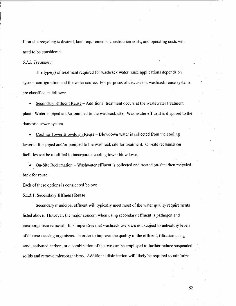
If on-site recycling is desired, land requirements, construction costs, and operating costs will
need to be considered.
5.1.3. Treatment
The type(s) of treatment required for washrack water reuse applications depends on
system configuration and the water source. For purposes of discussion, washrack reuse systems
are classified as follows:
• Secondary Effluent Reuse - Additional treatment occurs at the wastewater treatment
plant. Water is piped and/or pumped to the washrack site. Washwater effluent is disposed to the
domestic sewer system.
• Cooling Tower Slowdown Reuse - Slowdown water is collected from the cooling
towers. It is piped and/or pumped to the washrack site for treatment. On-site reclaimation
facilities can be modified to incorporate cooling tower blowdown.
• On-Site Reclamation - Washwater effluent is collected and treated on-site, then recycled
back for reuse.
Each of these options is considered below:
5.1.3.1. Secondary Effluent Reuse
Secondary municipal effluent will typically meet most of the water quality requirements
listed above. However, the major concern when using secondary effluent is pathogen and
microorganism removal. It is imperative that washrack users are not subject to unhealthy levels
of disease-causing organisms. In order to improve the quality of the effluent, filtration using
sand, activated carbon, or a combination of the two can be employed to further reduce suspended
solids and remove microorganisms. Additional disinfection will likely be required to minimize
62
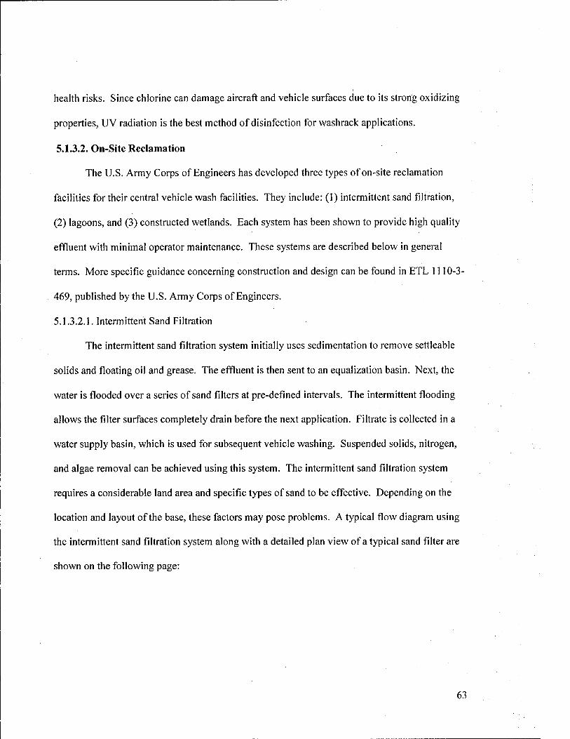
health risks. Since chlorine can damage aircraft and vehicle surfaces due to its strong oxidizing
properties, UV radiation is the best method of disinfection for washrack applications.
5.1.3.2. On-Site Reclamation
The U.S. Army Corps of Engineers has developed three types of on-site reclamation
facilities for their central vehicle wash facilities. They include: (1) intermittent sand filtration,
(2) lagoons, and (3) constructed wetlands. Each system has been shown to provide high quality
effluent with minimal operator maintenance. These systems are described below in general
terms. More specific guidance concerning construction and design can be found in ETL 1110-3-
469, published by the U.S. Army Corps of Engineers.
5.1.3.2.1. Intermittent Sand Filtration
The intermittent sand fihration system initially uses sedimentation to remove settleable
solids and floating oil and grease. The effluent is then sent to an equalization basin. Next, the
water is flooded over a series of sand filters at pre-defined intervals. The intermittent flooding
allows the filter surfaces completely drain before the next application. Filtrate is collected in a
water supply basin, which is used for subsequent vehicle washing. Suspended solids, nitrogen,
and algae removal can be achieved using this system. The intermittent sand filtration system
requires a considerable land area and specific types of sand to be effective. Depending on the
location and layout of the base, these factors may pose problems. A typical flow diagram using
the intermittent sand filtration system along with a detailed plan view of a typical sand filter are
shown on the following page:
63
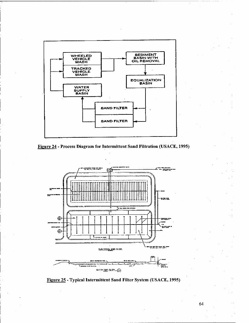
V^THEELED SEDIMENT BASIN WITH
WASH OIL REMOVAL j
TRACKED VEHICLE
WASH 1 r EQUALIZATION
BASIN WATER SUI*PL.Y BASIN
i i
SAMD FILTER
eAKir>rit<ri=n
Figure 24 - Process Diagram for Intermittent Sand Filtration (USAGE, 1995)
P^OW-TVPICWl s*Nn fllTtB
"I*???: "T.-N. ni.-'
Figure 25 - Typical Intermittent Sand Filter System (USAGE, 1995)
64
5.1.3.2.2. Lagoons
The lagoon system incorprates a series of two or three aerated lagoons like those
described in Section 4.3.1. They are normally operated in series to provide optimum
performance. The first lagoon is often used as an equalization basin located directly after
sedimentation. After lagoon treatment, the water is sent to a supply basin for reuse, similar to the
intermittent sand fihration system. High levels of BOD, COD, and suspended solids removal
can be achieved using these systems. Generally, the system is designed for a 14-day retention
time at peak flow conditions. Floating baffles can be used to control retention time and flow
through the lagoons. Lagoons should be lined to prevent seepage into the groundwater table. A
major advantage of lagoon-based systems is that they require little or no operator training. Other
than periodic checking for blocked inlets and outlets, they more or less operate independently.
However, as with intermittent sand filters, a large land area is required to support a lagoon
system. Further, algae blooms and habitation by birds and aquatic animals may degrade water
quality. The serviceable life of a lagoon-based treatment system is estimated at 15 to 20 years.
A typical flow diagram is shown below (USAGE, 1995):
WHEELED veHrcue
WASH i
i i TnACKeo VEHICLE
WASH SEDIMENT
BASIN WITH OIL nEMOVAL
SEDIMEMT BASIN
WITH OIL HEMOVAL
1 1 +
LAGOON
* WATER SUPPLV BASIN
LAGOON
1 Figure 25 - Process Diagram for Lagoon Washwater Treatment System (USAGE, 1995)
65

5.1.3.2.3. Constructed Wetlands
Use of constructed wetlands for washwater effluent treatment is yet another viable option. After
sedimentation, the water enters the constructed wetland, where BOD, suspended solids,
phosphorous, trace metals, and trace organics are removed. Constructed wetland use was
described previously in Section 4.5.2. In order to achieve high suspended solids removal, a
system retention time of between 2 to 7 days is required. A single wetland cell can be used or
muhiple cells in parallel or series can be employed. After treatment, the water is collected in a
supply basin for reuse, as with the other two systems. As with lagoon systems, constructed
wetlands must be lined to prevent groundwater infiltration. Minimal operator maintenance is
required for constructed wetlands, but they too take up a considerable amount of space. Further,
surface flow wetlands can be a breeding ground for mosquitoes, other insects and disease
vectors. Further, insect infestation can lead to destruction of wetland vegetation and decrease
treatment efficiency. Provisions for pest control must be included if a constructed wetland
configuration is used. Further, in cold climates the vegetation may not be as viable during winter
months as in warmer periods. A typical flow diagram is shown below (USACE, 1995):
WASH STRUCTURES
SEDIMENT BASIN WITH
Ott. REMOVAL
SEDIMENT BASIN WITH
OIL REMOVAL
WATER SUPPLY BASIN
CONSTRUCTED WETLAND
Figure 26 - Process Diagram for Constructed Wetland Treatment System (USACE, 1995)
66
5.1.3,3. Cooling Tower Slowdown Reuse
Blowdown water from cooling towers typically requires minimal treatment before it can
be used in washracks. Suspended solids and salt content are the only significant contaminants
that must be removed. If an on-site reclamation system is planned or already in place, the
blowdown water can be piped to the sedimentation basin and mixed with the washwater effluent.
Another option is to use sand filtration to remove suspended solids and pump the effluent to a
storage tank for washrack use. Depending on the size and number of cooling towers used on a
base, blowdown water quantities may not be sufficient to meet washrack water demand. As
such, it may need to be augmented by the potable water supply. However, even with this
configuration, potable water consumption will be reduced.
5.2. PLATING OPERATIONS
Plating involves application of a surface coating to an item in order to provide corrosion
resistance, wear resistance, or for decoration. The U.S. Navy operates plating shops on a number
of bases, which perform hard chrome plating, nickel, zinc, or cadmium plating, etching, and
phosphating, to name a few. There are three basic steps in the plating process; surface
preparation, plating, and post-treatment. After each step, rinsing is conducted to remove any
residue from the prior step. Virtually all of the water used in plating operations is during the
rinsing step (NFESC, 1993).
67
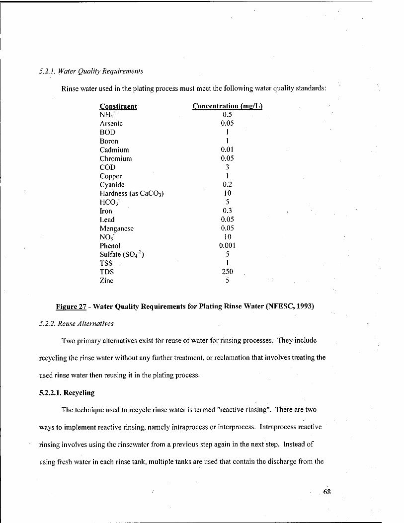
5.2.1. Water Quality Requirements
Rinse water used in the plating process must meet the following water quality standards:
Constituent NH/
Concentration (mg/L) 0.5
Arsenic 0.05 BOD 1 Boron 1 Cadmium 0.01 Chromium 0.05 COD 3 Copper Cyanide Hardness (as CaCOs) HCO3' Iron
1 0.2 10 5
0.3 Lead 0.05 Manganese 0.05 NOB-
Phenol 10
0.001 Sulfate (S04"^) TSS
5 1
IDS 250 Zinc 5
Figure 27 - Water Quality Requirements for Plating Rinse Water (NFESC, 1993)
5.2.2. Reuse Alternatives
Two primary alternatives exist for reuse of water for rinsing processes. They include
recycling the rinse water without any further treatment, or reclamation that involves treating the
used rinse water then reusing it in the plating process.
5.2.2.1. Recycling
The technique used to recycle rinse water is termed "reactive rinsing". There are two
ways to implement reactive rinsing, namely intraprocess or interprocess. Intraprocess reactive
rinsing involves using the rinsewater from a previous step again in the next step. Instead of
using fresh water in each rinse tank, multiple tanks are used that contain the discharge from the
68
prior step. After all steps are completed, the water is discharged. As long as there are no
harmful chemical interactions (i.e. between chemicals used for each step or harmful to the
process), this method can significantly reduce the amount of fresh water required for rinsing.
The interprocess method can be used when multiple plating operations are occurring. Here,
instead of having separate freshwater inputs to each rinse tank, rinse water from one process is
reused in the rinse tanks of another process (NFESC, 1993).
5.2.2.2. Reclamation
In order to produce rinse water that is high enough in quality to be used at the start or
throughout the plating process, chemical contaminants must be removed to the levels indicated in
Section 5.2.1. To do this, multiple advanced treatment processes may be required. As a first
step, the spent rinse water should be filtered using sand or activated carbon to remove suspended
solids. Next, either membrane processes, such as reverse osmosis and electrodialysis, or ion
exchange should be used to remove low-level contaminants. Another option is to separate the
clean rinsewater by evaporation. However, unless the solution is highly contaminated, this
option may be costly (due to energy requirements) and ineffective (NFESC, 1993).
5.3. MEAL CLEANING FACILIT lES
Metal cleaning facilities clean and prepare metal parts to ensure they perform correctly in
their respective applications. Chemicals are used to remove dirt, grease, rust, or other impurities
from metallic surfaces. The cleaning chemicals can be solvents, acids, detergents, or alkaline-
based. After metal cleaning has been performed, the parts are rinsed either by spraying or
submerging the parts in a rinse tank. Aircraft repair facilities, electroplating facilities, machine
69
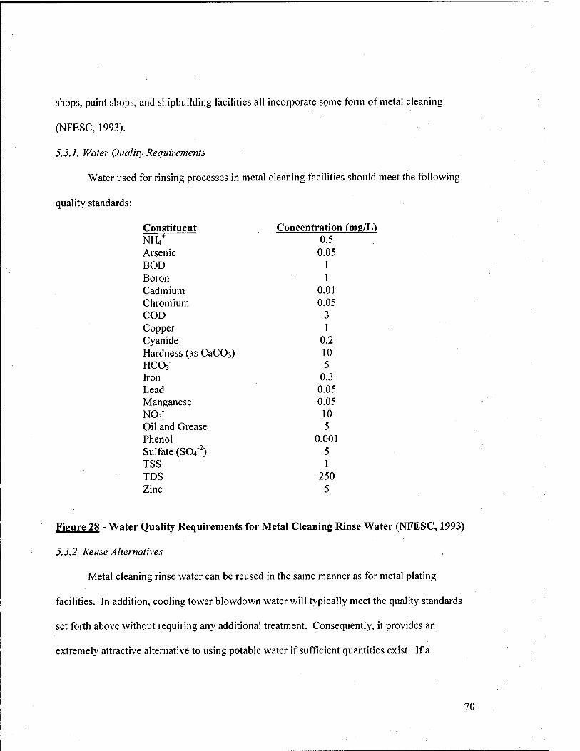
shops, paint shops, and shipbuilding facilities all incorporate some form of metal cleaning
(NFESC, 1993).
5.3.]. Water Quality Requirements
Water used for rinsing processes in metal cleaning facilities should meet the following
quality standards:
Constituent Concentration (mg/L) NH/ 0.5 Arsenic 0.05 BOD 1 Boron 1 Cadmium 0.01 Chromium 0.05 COD 3 Copper 1 Cyanide 0.2 Hardness (as CaCOs) 10 HCOa' 5 Iron 0.3 Lead 0.05 Manganese 0.05 NO3" 10 Oil and Grease 5 Phenol 0.001 Sulfate (S04"^) 5 TSS 1 TDS 250 Zinc 5
Figure 28 - Water Quality Requirements for Metal Cleaning Rinse Water (NFESC, 1993)
5.3.2. Reuse Alternatives
Metal cleaning rinse water can be reused in the same manner as for metal plating
facilities. In addition, cooling tower blowdown water will typically meet the quality standards
set forth above without requiring any additional treatment. Consequently, it provides an
extremely attractive alternative to using potable water if sufficient quantities exist. If a
70
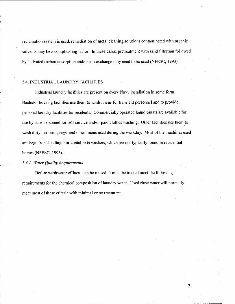
reclamation system is used, remediation of metal cleaning solutions contaminated with organic
solvents may be a complicating factor. In these cases, pretreatment with sand filtration followed
by activated carbon adsorption and/or ion exchange may need to be used (NFESC, 1993).
5.4. INDUSTRIAL LAUNDRY FACILITIES
Industrial laundry facilities are present on every Navy installation in some form.
Bachelor housing facilities use them to wash linens for transient personnel and to provide
personal laundry facilities for residents. Commercially operated laundromats are available for
use by base personnel for self-service and/or paid clothes washing. Other facilities use them to
wash dirty uniforms, rags, and other linens used during the workday. Most of the machines used
are large front-loading, horizontal-axis washers, which are not typically found in residential
homes (NFESC, 1993).
5.4.1. Water Quality Requirements
Before washwater effluent can be reused, it must be treated meet the following
requirements for the chemical composition of laundry water. Used rinse water will normally
meet most of these criteria with minimal or no treatment.
71
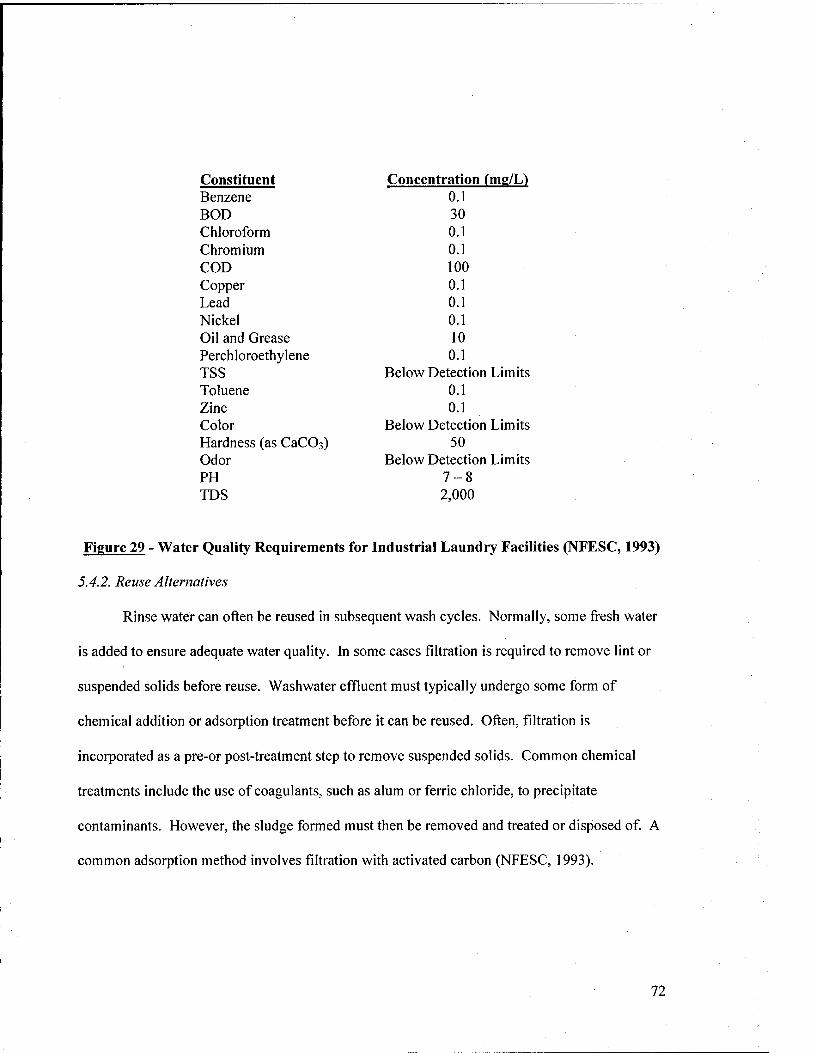
Constituent Concentration (me/L) Benzene 0.1 BOD 30 Chloroform 0.1 Chromium 0.1 COD 100 Copper 0.1 Lead 0.1 Nickel 0.1 Oil and Grease 10 Perchloroethylene 0.1 TSS Below Detection Limits Toluene 0.1 Zinc 0.1 Color Below Detection Limits Hardness (as CaCOs) 50 Odor Below Detection Limits PH 7-8 IDS 2,000
Figure 29 - Water Quality Requirements for Industrial Laundry Facilities (NFESC, 1993)
5.4.2. Reuse Alternatives
Rinse water can often be reused in subsequent wash cycles. Normally, some fresh water
is added to ensure adequate water quality. In some cases filtration is required to remove lint or
suspended solids before reuse. Washwater effluent must typically undergo some form of
chemical addition or adsorption treatment before it can be reused. Often, filtration is
incorporated as a pre-or post-treatment step to remove suspended solids. Common chemical
treatments include the use of coagulants, such as alum or ferric chloride, to precipitate
contaminants. However, the sludge formed must then be removed and treated or disposed of. A
common adsorption method involves filtration with activated carbon (NFESC, 1993).
72
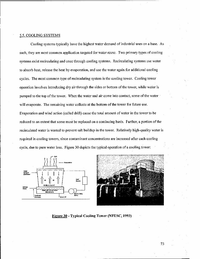
5.5. COOLING SYSTEMS
Cooling systems typically have the highest water demand of industrial uses on a base. As
such, they are most common application targeted for water reuse. Two primary types of cooling
systems exist recirculating and once through cooling systems. Recirculating systems use water
to absorb heat, release the heat by evaporation, and use the water again for additional cooling
cycles. The most common type of recirculating system is the cooling tower. Cooling tower
operation involves introducing dry air through the sides or bottom of the tower, while water is
pumped to the top of the tower. When the water and air come into contact, some of the water
will evaporate. The remaining water collects at the bottom of the tower for future use.
Evaporation and wind action (called drift) cause the total amount of water in the tower to be
reduced to an extent that some must be replaced on a continuing basis. Further, a portion of the
recirculated water is wasted to prevent salt buildup in the tower. Relatively high-quality water is
required in cooling towers, since contaminant concentrations are increased after each cooling
cycle, due to pure water loss. Figure 30 depicts the typical operation of a cooling tower:
Sprayed Downward
Makeup Water
—p^—7^:—7'^ T'^—7^
Ail Blown UjJwarcf
Watar wfth CoacertrMed Mineral Sattt
Trealinant Chemicals
Rvdrciiating Pump
Figure 30 - Typical Cooling Tower (NFESC, 1993)
73
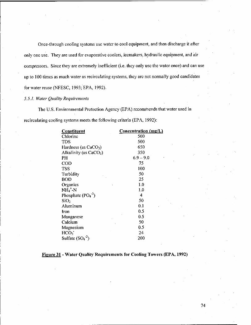
Once-through cooling systems use water to cool equipment, and then discharge it after
only one use. They are used for evaporative coolers, icemakers, hydraulic equipment, and air
compressors. Since they are extremely inefficient (i.e. they only use the water once) and can use
up to 100 times as much water as recirculating systems, they are not normally good candidates
for water reuse (NFESC, 1993; EPA, 1992).
5.5.7. Water Quality Requirements
The U.S. Environmental Protection Agency (EPA) recommends that water used in
recirculating cooling systems meets the following criteria (EPA, 1992):
Constituent Concentration fmg/L) Chlorine 500 TDS 500 Hardness (as CaCOa) 650 Alkalinity (as CaCOs) 350 PH 6.9-9.0 COD 75 TSS 100 Turbidity 50 BOD 25 Organics 1.0 NH4^-N 1.0 Phosphate (P04"^) 4 Si02 50 Aluminum 0.1 Iron 0.5 Manganese 0.5 Calcium 50 Magnesium 0.5 HCO3' 24 Sulfate (S04"^) 200
Figure 31 - Water Quality Requirements for Cooling Towers (EPA, 1992)
74
5.5.2. Potential Water Sources
The principal sources of water for cooling towers are secondary municipal effluent and
used make-up water from once-through cooling systems. In most cases, secondary effluent is a
more viable source, due to the large quantities available and minimal treatment requirements.
Further, blowdown water from the cooling towers can often be used in other applications such as
metal cleaning, washracks, and metal plating, as previously indicated.
5.5.3. Treatment Requirements
While secondary effluent is often nearly "clean" enough to be used in cooling towers,
some degree of treatment must usually be done to prevent operating problems. Generally
speaking, there are four types of problems that can be encountered when using secondary
effluent. Cooling tower operators will not normally experience these problems when water that
is treated to meet standards listed in Section 5.5.1.
5.5.3.1. Scaling
Scaling is the buildup of hard deposits on pipe (or other metallic) surfaces, which reduce
the efficiency of the cooling towers. Scales are typically caused by calcium and magnesium
deposits from constituents in the process water. There are a number of ways to control scale
formation. Reducing pH by adding acids such as sulfuric acid, hydrochloric acid, COzgas, and
SO2 gas limits the solubility of scale-forming compounds. Lime addition can be performed to
remove hardness and alum addition can be done to remove phosphates. These processes must be
followed by sedimentation to remove settled solids. Finally, ion exchange can be used to remove
metal cations (i.e. Ca''^ Mn^^ Mg"'^ etc.) in the water (Metcalf and Eddy, 2003; EPA, 1992).
75
5.5.3.2. Corrosion
Corrosive conditions on metallic surfaces are more likely when using secondary effluent
as compared to potable water, due to the significantly higher TDS concentrations present. TDS
increases electrical conductivity in the water, which in turn promotes corrosion. Manganese,
iron, aluminum, and dissolved oxygen all contribute to the corrosive potential, since they are
strong oxidants. Further, low pH waters (pH < 6.5) will also foster corrosion. Lime or soda ash
addition can be performed to raise pH. Corrosion inhibitors, such as polyphosphates and
polysilicates can also be used. Ion exchange and reverse osmosis are also viable options, but are
often cost prohibitive for this type of application (Metcalf and Eddy, 2003; EPA, 1992).
5.5.3.3. Biological Growth
The moist environment of the cooling tower promotes microbial growth. This is a
problem on two fronts. First, process efficiency and water flow may be reduced in the tower,
along with possible generation of corrosive by-products. Second, microorganisms and pathogens
emitted in evaporated water and drift can be a health hazard for personnel working near the
cooling towers, or others who may be exposed. The primary constituents of concern include
organic matter (BOD), nitrogen, and phosphorous. Two approaches may be used to inhibit
biological growth. Chlorine or other disinfectants can be added to the secondary effluent to
control biological growth and remove pathogens. Additionally, advanced treatment of the
secondary effluent, such as nitrification, denitrification, biological phosphorous removal,
coagulation and flocculation, and fihration may be employed to further reduce nutrient
availability in the water. Most of these processes (except filtration) will require sedimentation to
remove settled solids (Metcalf and Eddy, 2003; EPA, 1992).
76
5.5.3.4. Fouling
Fouling is defined as the attachment and growth of deposited materials in cooling towers.
Deposits may contain biological matter, suspended solids, scale, or corrosion by-products. As
with other operational problems, performance efficiency is reduced as a result of fouling.
Fouling is normally controlled by the use of chemical dispersants to prevent particulate
formation or with pretreatment using coagulants and/or filtration. Pretreatment can include a
separate coagulation/flocculation process followed by sedimentation or filtration. Phosphorous
removal using alum or ferric chloride has been shown to be very effective in reducing fouling
(Metcalf and Eddy, 2003; EPA, 1992).
77
6. IRRIGATION
Irrigation can create substantial water demands on Navy facilities. The majority of bases
have large grass-covered areas, including residential and office lawns, recreational fields,
airfields, grassy medians, shoulders along roads, and parade fields, to name a few. Further,
many bases have golf courses, which require constant watering to provide high-quality playing
surfaces. In fact, the bulk of irrigation on Navy bases is done on golf courses. Often, golf
courses will use manmade lakes that collect rainwater and natural runoff, but these sources are
often not sufficient to provide for peak demand, especially during summer months or dry
periods. Instead, they often have to rely on underground wells or potable sources to meet
irrigation requirements.
This section considers the potential water reuse applications for irrigation on Navy
installations. The primary focus is on golf course irrigation using secondary municipal effluent,
since it requires the most water and is the most widely implemented practice to date. Irrigation
in non-residential and recreational areas is also considered. Finally, residential lawn irrigation
using greywater systems is addressed. Agricultural irrigation is not considered in this report for
two of reasons. Although the Navy leases some of its unused land for agricultural use, this is
neither a mission-essential function nor a morale/ recreation issue. Second, unless an
agricultural lease is already in place, implementing a water reuse strategy is not a likely catalyst
to get one started. However, bases with existing agricultural leases may consider using treated
municipal effluent as an irrigation source. Design considerations are similar to those for golf
courses, with additional provisions for the type(s) of crops grown.
78
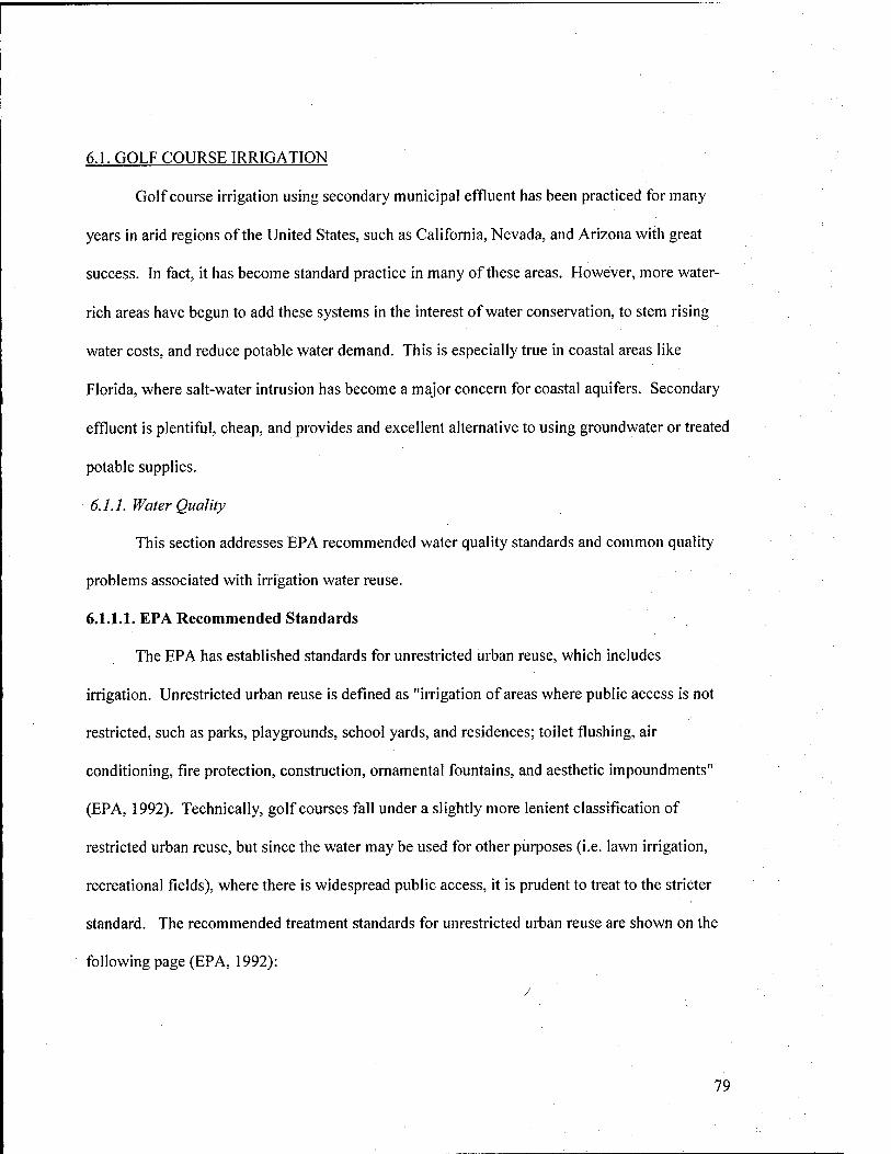
6.1. GOLF COURSE IRRIGATION
Golf course irrigation using secondary municipal effluent has been practiced for many
years in arid regions of the United States, such as California, Nevada, and Arizona with great
success. In fact, it has become standard practice in many of these areas. However, more water-
rich areas have begun to add these systems in the interest of water conservation, to stem rising
water costs, and reduce potable water demand. This is especially true in coastal areas like
Florida, where salt-water intrusion has become a major concern for coastal aquifers. Secondary
effluent is plentiful, cheap, and provides and excellent alternative to using groundwater or treated
potable supplies.
6.1.1. Water Quality
This section addresses EPA recommended water quality standards and common quality
problems associated with irrigation water reuse.
6.1.1.1. EPA Recommended Standards
The EPA has established standards for unrestricted urban reuse, which includes
irrigation. Unrestricted urban reuse is defined as "irrigation of areas where public access is not
restricted, such as parks, playgrounds, school yards, and residences; toilet flushing, air
conditioning, fire protection, construction, ornamental fountains, and aesthetic impoundments"
(EPA, 1992). Technically, golf courses fall under a slightly more lenient classification of
restricted urban reuse, but since the water may be used for other purposes (i.e. lawn irrigation,
recreational fields), where there is widespread public access, it is prudent to treat to the stricter
standard. The recommended treatment standards for unrestricted urban reuse are shown on the
following page (EPA, 1992):
79
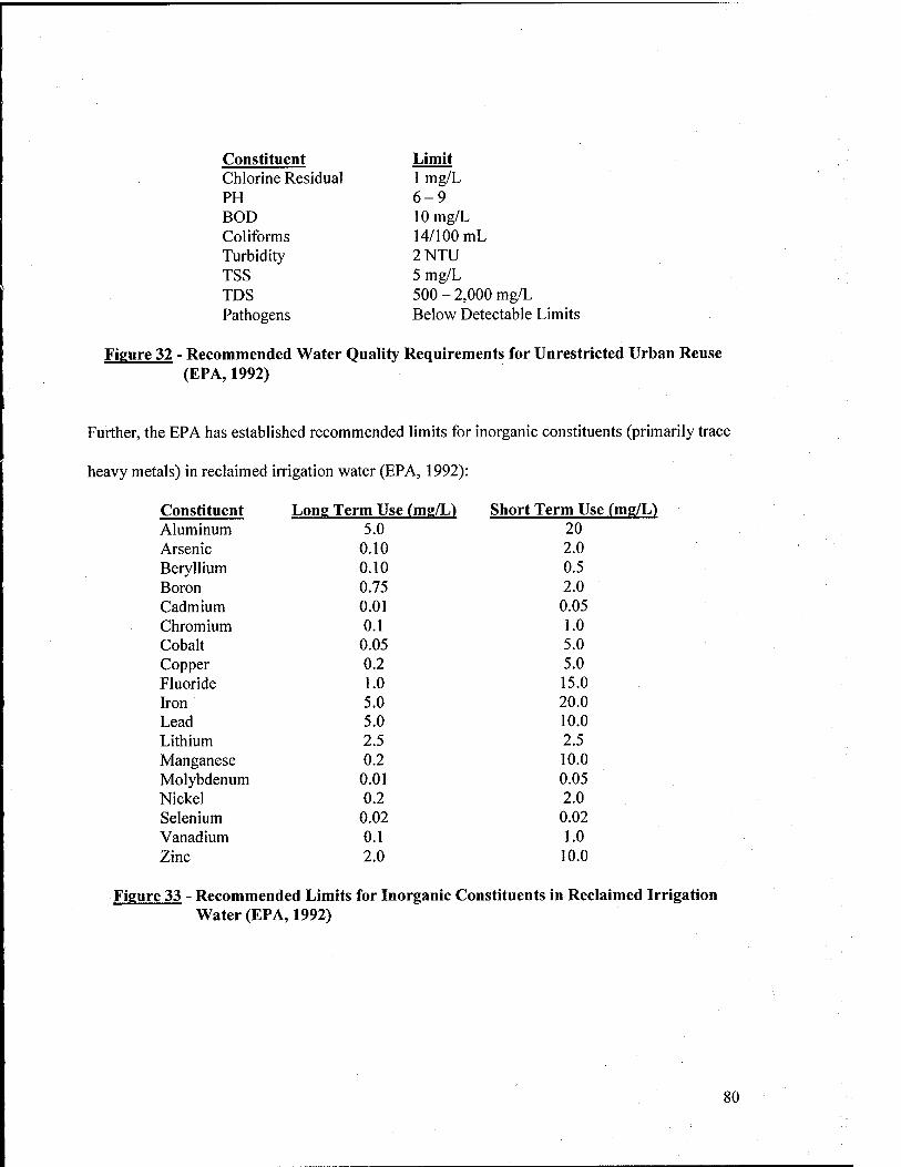
Constituent Limit Chlorine Residual 1 mg/L PH 6-9 BOD 10 mg/L Coliforms 14/100 mL Turbidity 2NTU TSS 5 mg/L TDS 500-2,000 mg/L Pathogens Below Detectable Limits
Figure 32 - Recommended Water Quality Requirements for Unrestricted Urban Reuse (EPA, 1992)
Further, the EPA has established recommended limits for inorganic constituents (primarily trace
heavy metals) in reclaimed irrigation water (EPA, 1992):
Constituent Long Term Use (mg/L) Short Term Use (mg/L) Aluminum 5.0 20 Arsenic 0.10 2.0 Beryllium 0.10 0.5 Boron 0.75 2.0 Cadmium 0.01 0.05 Chromium 0.1 1.0 Cobalt 0.05 5.0 Copper 0.2 5.0 Fluoride 1.0 15.0 Iron 5.0 20.0 Lead 5.0 10.0 Lithium 2.5 2.5 Manganese 0.2 10.0 Molybdenum 0.01 0.05 Nickel 0.2 2.0 Selenium 0.02 0.02 Vanadium 0.1 1.0 Zinc 2.0 10.0
Figure 33 - Recommended Limits for Inorganic Constituents in Reclaimed Irrigation Water (EPA, 1992)
8
6.1.1.2. Potential Quality Problems
Secondary municipal effluent will normally have more impurities than groundwater or
surface water supplies, including metal ions and other trace elements, chlorine residuals, and
nutrients. Some of these constituents may cause problems in the turf grass and/or underlying
soils. The key indicators for judging irrigation water quality are salinity, sodium levels, toxic
element concentrations, bicarbonate, pH, and nutrient content. Each factor is addressed below.
6.1.1.2.1. Salinity
When soluble salts build up in the root zone, due to high concentrations in applied
irrigation water, salinity problems may result. Salinity reduces water uptake by lowering
osmotic potential in the soil. As a result, plants use most of their energy to adjust salt
concentration to get enough water instead of on plant grov^h. This problem is most severe in hot
and dry climates. Further, concentrations of ions, such as sodium, chloride, and boron can build
up in the soil over time and cause human health hazards or become toxic to plant life. Salinity
problems generally occur in irrigation waters with electrical conductivities (ECw) greater than
0.75 dS/m. Severe problems occur when water with ECw of 3.0 dS/m or higher is used. Golf
course grasses must be evaluated to determine if they can tolerate salinity in reclaimed
wastewater, or the water must be treated to remove salts. Below 3.0 dS/m most turf grasses are
not significantly affected. Between 3 to 10 dS/m, most turf grass growth is restricted, and above
10 dS/m, only the most tolerant grasses will grow. The following table indicates the relative
salinity tolerances of common turf grasses. Tolerance ratings are based on soil salt levels and
defined as follows (USGA, 1994; EPA, 1992):
• Sensitive (S): < 3 dS/m • Moderately Sensitive (MS): 3-6 dS/m • Moderately Tolerant (MTV 6-10 dS/m • Tolerant m: lOdS/m
81
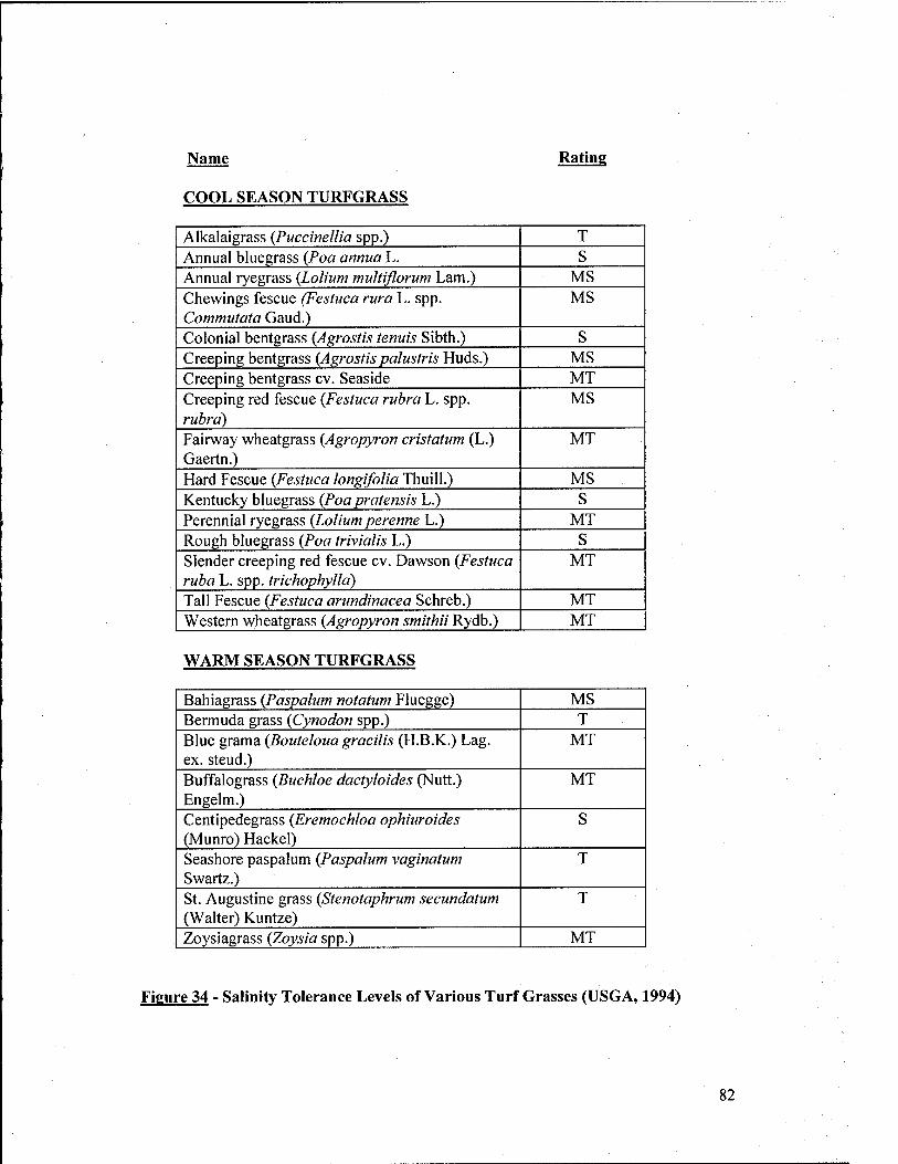
Name Rating
COOL SEASON TURFGRASS
Alkalaigrass {Puccinellia spp.) T Annual bluegrass {Poa annua L. S Annual ryegrass {Lolium multiflorum Lam.) MS Chewings fescue (Festuca rura L. spp. Commutata Gaud.)
MS
Colonial bentgrass (Agrostis tenuis Sibth.) S Creeping bentgrass {Agrostis palustris Huds.) MS Creeping bentgrass cv. Seaside MT Creeping red fescue {Festuca rubra L. spp. rubra)
MS
Fairway wheatgrass {Agropyron cristatum (L.) Gaertn.)
MT
Hard Fescue {Festuca longifolia Thuill.) MS Kentucky bluegrass {Poa pratensis L.) S Perennial ryegrass {Lolium perenne L.) MT Rough bluegrass {Poa trivialis L.) S Slender creeping red fescue cv. Dawson {Festuca ruba L. spp. trichophylla)
MT
Tall Fescue {Festuca arundinacea Schreb.) MT Western wheatgrass {Agropyron smithii Rydb.) MT
WARM SEASON TURFGRASS
Bahiagrass {Paspalum notatum Fluegge) MS Bermuda grass {Cynodon spp.) T Blue grama {Bouteloua gracilis (H.B.K.) Lag. ex. steud.)
MT
Buffalograss {Buchloe dactyloides (Nutt.) Engelm.)
MT
Centipedegrass {Eremochloa ophiuroides (Munro) Hackel)
S
Seashore paspalum {Paspalum vaginatum Swartz.)
T
St. Augustine grass {Stenotaphrum secundatum (Walter) Kuntze)
T
Zoysiagrass {Zoysia spp.) MT
Figure 34 - Salinity Tolerance Levels of Various Turf Grasses (USGA, 1994)
82
6.1.1.2.2. Sodium
High levels of sodium in reclaimed irrigation water can lead to reduced permeability and
aeration in underlying soil. This is because sodium salts affect the cation composition in the first
few inches of soil. Typically, this phenomenon occurs when there is high sodium content and/or
low calcium or magnesium content in the irrigation water. Calcium and magnesium ions tend to
stabilize the soil structure, where sodium has a destabilizing effect. The effect of irrigation water
on permeability of a soil is expressed using the Sodium Adsorption Ratio (SAR), which is
defined below:
SAR = Na Na = sodium ion concentration (meq/L) [(Ca + Mg)/2]'^^ Ca = calcium ion concentration (meq/L)
Mg = magnesium ion concentration (meq/L)
Waters with SAR greater than 9 can cause significant permeability problems in clay soils over
time. Sandy soils can tolerate a SAR of this magnitude with less impact. Golf courses that have
been designed with sandy soils that drain well are less susceptible to problems from high SAR
irrigation waters (USGA, 1994; EPA, 1992).
6.1.1.2.3. Toxic Elements
Trace toxic elements in reclaimed wastewater may pose potential problems if allowed to
accumulate to toxic levels in the soil or turf grasses. Boron, chloride, and sodium cause the most
problems with plant toxicity. Chloride concentrations greater than 355 mg/L or sodium levels of
70 mg/L or more can cause damage to ornamental plants. Boron is most likely to cause toxicity
problems in turf grass. It usually comes from soap and detergent residues still in the secondary
effluent. It can cause problems at concentrations higher than 2.0 mg/L. Some heavy metals like
zinc and copper are actually good for turf grass, but others such as nickel, molybdenum, and
cadmium can cause adverse effects in plants, animals, and humans. To minimize problems from
83
trace toxic elements, water should be treated to meet the standards listed in Section 6.1.1.1
(USGA, 1994; EPA, 1992).
6.1.1.2.4. Bicarbonate
Bicarbonate (HCO3') may also affect soil permeability, similar to sodium. It will
combine with calcium or magnesium ions to form calcium or magnesium carbonate precipitates
(CaCOs (s) or MgCOs (s)). As a result, the SAR will increase leading to permeability problems.
Further, high bicarbonate concentrations will tend to increase soil pH. Typically, bicarbonate
concentrations less than 1.5 meq/L are desired (USGA, 1994).
6.1.1.2.5. pH
The desired pH range for most soils is 5.5 - 7.0. Irrigation water pH should be around
6.5 - 8.4. Waters out of this range need to be evaluated for other constituents, such as
bicarbonate, which will cause permeability problems as previously described. In addition, soils
in the western U.S. often have naturally high pH and may cause iron or other elemental
deficiencies in plants grown in them (USGA, 1994).
6.1.1.2.6. Nutrients
Nitrogen, phosphorous, and potassium are often present in secondary effluents. These
nutrients have a beneficial impact on turf grass grovv1:h. However, much of the nitrogen and
phosphorous may be removed during secondary and advanced treatment at the wastewater
treatment plant. As such, fertilizers and supplements may still be required to ensure proper grass
growth. Further, while nitrogen is beneficial to plant growth, surplus amounts can seep into
groundwater, potentially causing NPDES permit limits to be exceeded (USGA, 1994; EPA,
1992).
84
6.1.2. Water Treatment Requirements
In order to meet EPA recommended standards for unrestricted urban reuse (see Section
6.1.1.1.), secondary treatment, disinfection, and filtration are normally required. Virtually all
municipal effluents have undergone secondary treatment and disinfection to meet Federal and
state discharge requirements. However, the level of advanced treatment varies by locality. The
primary concern in using municipal wastewater effluents for irrigation purposes is the
minimization of health risks due to disease vectors in the water. Adequate disinfection is
required to ensure pathogens and viruses have been killed. It is also recommended that a
chlorine residual of 0.5 to 1 mg/L is maintained to prevent odors and inhibit bacterial regrowth.
Advanced treatment may include coagulation/flocculation followed by sedimentation or
coagulant addition before filtration to remove many of the toxic elements listed in Section
6.1.1.1 (EPA, 1992). Ion exchange may also be a viable option, but can be considerably more
expensive. Strategies for dealing with the common water quality problems described in the
previous section are described below:
6.1.2.1. Salinity
There are a number of methods, both physical and chemical, to deal with irrigation waters
that have high SAR ratios. Poor quality water can be blended with less salty water using a
reservoir or storage pond. This can involve mixing with potable supplies and/or natural runoff
from precipitation and other sources. Another option is to apply extra water than required to
leach excess salt below the root zone. When designing a new golf course, it is advisable to plant
grasses with a high salinity tolerance. If hard soils or clayey soils are present, replace them with
more permeable sandy soils. If poor drainage conditions exist or if the water table is shallow,
artificial drainage can be installed (USGA, 1994). The water may also be treated to remove
85
some or most of the sodium ions using filtration, coagulant addition (and subsequent
flocculation/sedimentation), and ion exchange.
6.1.2.2. Sodium
Sodium-related permeability problems can be mitigated using many of the same
techniques for salinity. In addition, gypsum, sulfur, or sulfur dioxide may be applied to increase
soluble calcium ion concentrations in the soil (USGA, 1994).
6.1.2.3. Toxic Elements
In order to minimize accumulation of toxic elements in the soil, a number of techniques
may be used. Similar to dealing with salinity and sodium problems, water can be blended with
potable supplies and/or natural runoff from precipitation in a reservoir or storage pond. Also,
excess or more frequent irrigation can be employed to prevent constituent buildup and encourage
leaching out of the root zone (USGA, 1994).
6.1.2.4. Bicarbonate
Bicarbonate permeability problems can be mitigated in the same manner as salinity. If
coagulant addition is performed, alum or ferric chloride should be used, since they will remove
bicarbonate alkalinity through precipitation. Lime addition will generate significantly more
sludge than alum or ferric chloride, and is therefore not recommended for this purpose (Hao,
2003). Limiting pH increases resulting from high bicarbonate concentrations can be done by
adding acids to the irrigation water (i.e. sulfuric acid, phosphoric acid) or by using acidifying
fertilizers like ammonium sulfate (USGA, 1994).
6.1.2.5. pH
Soil pH outside the recommended range should be adjusted up or down to promote
optimal growth conditions. If a soil is too acidic, lime can be added to increase pH. Conversely,
86
acidifying fertilizers can be added to decrease pH in ali<;aline soils. It is important to consider
soil pH, texture, percent saturation, characteristics of the additive material, and turf grass species
before implementing a pH adjustment scheme (USGA, 1994).
6.1.2.6. Nutrients
Nitrogen is often the constituent of concern, since permitted discharges are typically very
strict. Nitrification and/or denitrification processes may need to be incorporated into biological
treatment at the wastewater treatment plant or separate units, such as denitrifying filters may
need to be installed. Similarly, phosphorous removal during biological treatment or by
coagulation, flocculation, and sedimentation can be performed. Another option is land treatment
of the secondary effluent (i.e. slow-rate filtration). In some cases, the grass and natural soils may
remove nutrients to acceptable levels. The depth to groundwater and/or potable aquifers will
partially determine the effectiveness and acceptability of land treatment. Consequently, the
nutrient requirements of turf grass as well as removal potential by the soils must be studied
before a treatment scheme is implemented.
6.1.3. System Design Requirements
This section considers the various design requirements for new systems and/or
modifications that must be made to existing irrigation systems to allow for non-potable water
reuse.
6.1.3.1. Water Distribution System
Design requirements are similar to those for a standard potable distribution system.
Materials of equal quality and construction are recommended. Distribution mains should be
sized to accommodate peak hourly demands. Typically, watering will occur at night when there
is a minimum chance of contact with golfers. The system must be sized to meet demand during
87
this window. If storage lakes are used, filtration should be provided for water pumped from the
lake. This will prevent clogging of the pump. The inlet from the lake should have a primary
screen (10-30 mesh) to prevent large objects from entering the pump. Self-cleaning screens
prevent the need for manual cleaning. Sprinklers that have a precipitation rate less than or equal
to the soil infiltration rate should be chosen to prevent runoff Impact heads are desirable since
they are less apt to clog. Flush valves should be installed in low spots and dead-ends (USGA,
1994; EPA, 1992).
6.1.3.2. Pressure and Flow Requirements
System pressure for irrigation systems can be as low as 10 psi (70 kPa) if booster pumps
are provided at the point of delivery. If not, maximum system pressure can be as high as 100 to
150 psi (700 to 1000 kPa). Flow controllers should be installed, since they will shutdown the
water line if a pipe breaks. Also, irrigation schedules should be developed to avoid ponding and
runoff. Drains should be installed on greens, tees, fairways, and roughs. Preventing compaction
is also important for good drainage. One method is to install cart paths when feasible. Drainage
should normally be retained on site, either by channeling back to the storage facilities or into a
large gravel sump. Discharge into sewer systems normally requires an NPDES permit (USGA,
1994; EPA, 1992).
6.1.3.3. Identification of Piping and Appurtenances
All piping and appurtenances in a non-potable distribution system should be clearly and
consistently identified. Color coding and marking are two common identification techniques.
An example of a marking is "CAUTION: NON-POTABLE WATER - DO NOT DRINK".
Markings may be stenciled or taped to the pipes. If pipes are colored, they should clearly stand
88
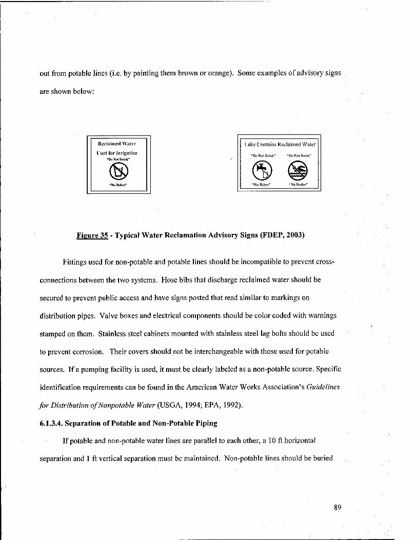
out from potable lines (i.e. by painting them brown or orange). Some examples of advisory signs
are shown below:
Reclaimed Water
I'sed for Irrigation "Do Not Drink"
Lake Contains Reclaimed Water
"Do Not Drink" "Do Nol Swim"
Figure 35 - Typical Water Reclamation Advisory Signs (FDEP, 2003)
Fittings used for non-potable and potable lines should be incompatible to prevent cross-
connections between the two systems. Hose bibs that discharge reclaimed water should be
secured to prevent public access and have signs posted that read similar to markings on
distribution pipes. Valve boxes and electrical components should be color coded with warnings
stamped on them. Stainless steel cabinets mounted with stainless steel lag bolts should be used
to prevent corrosion. Their covers should not be interchangeable with those used for potable
sources. If a pumping facility is used, it must be clearly labeled as a non-potable source. Specific
identification requirements can be found in the American Water Works Association's Guidelines
for Distribution of Nonpotable Water {liSGA, 1994; EPA, 1992).
6.1.3.4. Separation of Potable and Non-Potable Piping
If potable and non-potable water lines are parallel to each other, a 10 ft horizontal
separation and 1 ft vertical separation must be maintained. Non-potable lines should be buried
89
deeper than potable lines to prevent infiltration. In most cases, non-potable lines should be
buried at least 3 ft below grade (EPA, 1992).
6.1.3.5. Site Characteristics
In order to properly evaluate a site for irrigation using reclaimed water, a number of
factors must be considered. They include topography, soil characteristics, groundwater, and
climate.
6.1.3.5.1. Topography
Topographical considerations include slope, relief, and susceptibility to flooding. A
site's potential to add stormwater runoff, create drainage problems, promote groundwater
seepage, and relief drainage must all be evaluated. Steep slopes are not desirable since they
increase the amount of runoff and erosion. They also lead to unstable soil conditions, and can be
expensive to irrigate due excessive to runoff. Typically, no more than 15 to 20% slope is
recommended at the site. Relief is defined as elevation changes at a site, such as hills and
valleys. Too much relief increases pumping costs, since additional power must be supplied to
overcome elevation increases. Finally, the potential for flooding must also be considered. Flood
maps created by the National Flood Insurance Program and Federal Emergency Management
Association should be consulted to determine if the area is in a floodplain. Floodplains have
highly variable drainage conditions and are more susceptible to equipment damage and
contamination in heavy precipitation events (Pettygrove and Asano, 1985).
6.1.3.5.2. Soils
The types of soils present (or planned) at a site need to be identified as well as their
physical, chemical, and drainage characteristics. Soil surveys are normally available from Soil
Conservation Service (SCS) or the U.S. Geological Service (USGS). Infiltration rate and
90
hydraulic conductivity are key hydraulic factors that need to be determined for a soil. Minimum
infiltration rate must be known to design sprinkler systems. For multiple or mixed strata, the
lowest hydraulic conductivity is the usually determining factor. Soil chemistry, such as pH and
electrical conductivity, must also be considered to determine how reuse water application will
impact soil vegetation, permeability, and durability of the soil matrix (Pettygrove and Asano,
1985).
6.1.3.5.3. Groundwater
It is extremely important to evaluate the sources of groundwater present at the site.
Depth to groundwater and groundwater quality are the most significant parameters that must be
evaluated. Groundwater depths greater than 3 or 4 ft are usually preferred, especially when land
treatment is employed. Some states require greater depths to prevent groundwater
contamination, depending on the quality of the aquifer. Groundwater aquifers are classified
according to their quality. High-quality (i.e. potable) aquifers will have more stringent
regulations than lower quality aquifers (Pettygrove and Asano, 1985).
6.1.3.5.4. Climate
In order to determine the required irrigation water quantities and application cycles,
climatic factors must be studied. Historical monthly and annual precipitation and temperature,
length of the growing season, and prevailing winds are some of the criteria that should be
evaluated when designing a system and determining its feasibility.
6.1.3.6. Backflow Prevention
Some form of backflow prevention is required to protect potable water supplies. If a
potable source exists near the pumping facility, an air gap should be created to prevent backflow
into the potable system. If the possibility of cross-connection exists, such as in areas where both
91
potable and non-potable sources are present, backflow prevention devices must be placed on the
potable water line to prevent potential intermixing with backflow from the non-potable source.
Backflow prevention is not normally required on the non-potable system, except when on-site
chemical addition is performed for irrigation purposes (EPA, 1992).
6.2. OTHER NON-AGRICULTURAL IRRIGATION
Other non-agricultural irrigation applications include watering lawns around office and
industrial facilities, recreational fields, airfields, grassy medians, shoulders along roads, and
parade fields, as previously indicated. EPA guidelines for unrestricted urban reuse hold for these
applications. Similar design considerations and water quality issues to those faced when
planning golf course irrigation reuse can be assumed. In most cases, these areas are not irrigated
with either the frequency or quantity of water used for golf courses. Many bases, especially
those in wetter climates (i.e. U.S. east coast) do not irrigate these areas at all. However, they
provide additional options for using reclaimed water when a water reuse scheme is being
planned. Ultimately, increasing water reuse consumption on a base will reduce the amount of
secondary effluent (and contaminants) discharged to receiving waters.
6.3. RESIDENTIAL LAWN IRRIGATION
The most feasible water reuse application for residential lawn irrigation involves the use
of greywater collected from bathroom sinks, washing machines, and/or showers in the home.
The water can be stored, treated, and used in place of potable supplies. There are a number of
design and health issues that must be considered before a greywater irrigation system is installed.
92
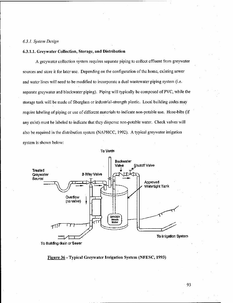
6.3.1. System Design
6.3.1.1. Greywater Collection, Storage, and Distribution
A greywater collection system requires separate piping to collect effluent from greywater
sources and store it for later use. Depending on the configuration of the home, existing sewer
and water lines will need to be modified to incorporate a dual wastewater piping system (i.e.
separate greywater and blackwater piping). Piping will typically be composed of PVC, while the
storage tank will be made of fiberglass or industrial-strength plastic. Local building codes may
require labeling of piping or use of different materials to indicate non-potable use. Hose-bibs (if
any exist) must be labeled to indicate that they dispense non-potable water. Check valves will
also be required in the distribution system (NAPHCC, 1992). A typical greywater irrigation
system is shown below:
To Vents
Treated Graywater Source'
Backvi'ater Valve ShutoUfVaiv©
3-Way Valvo |J /TKtt>Ejiri
Approved Watertight Tank
To Building drain or Sewsr
To Irrigation System
Figure 36 - Typical Greywater Irrigation System (NFESC, 1993)
93
6.3.1.2. Irrigation Methods
Many states have approved greywater irrigation systems for domestic use, but have
limited the applications to sub-surface irrigation only. This is because aboveground irrigation
with greywater, especially if it is untreated (as if often the case) can create unnecessary health
risks. Also, greywater systems typically operate at very low pressure (usually by gravity flow)
and may not be adequate to service hose bibs, sprinkler heads, or arcing sprinklers. The most
common types of irrigation systems are mini-leach fields and drip irrigation (NAPHCC, 1992;
Milne, 1979).
A mini-leach field is constructed by digging a trench along the outer perimeter of the
lawn (or vegetated area) and filling it with gravel about 4 inches from surface. An open tube or
perforated pipe opening is located at the top of the gravel surface, which provides greywater
input from the storage tank. The gravel is lined with building paper or vveed-stop to prevent
vegetation in the gravel. The trench is then filled to the ground surface with soil. Mini-leach
fields are relatively cheap and easy to install and can be very effective. However, they are best
suited for irrigation of trees and other deep-rooted plants.
A drip irrigation system uses a pipe or hose to carry water from the storage tank to the
irrigation area. The pipe is sloped downhill to provide gravity flow. Smaller perforated tubes
(called drip lines) are connected to the main tube at right angles, which distribute the water
evenly in the lawn. Drip lines are normally buried 4 to 12 inches below ground surface. One
advantage of a drip irrigation system is high efficiency and little evaporation loss. Also, these
systems work well in areas where salinity is high. Since flow is constantly downward, salts are
leached past the root zone so they don't build up in the grass. Also, they can be used on uneven
terrain. Two major disadvantages exist. First, drip irrigation systems can be expensive to install.
94
Second, they can get clogged if suspended solids are not first removed by filtration (NAPHCC,
1992; Milne, 1979).
63.2. Treatment Requirements
Generally speaking, many of the same problems for golf course irrigation water quality
apply to residential greywater systems. Odor control, nutrient limitation, and pathogen removal
top the list of concerns. The most common treatment techniques are filtration and disinfection.
Filtration is performed to remove suspended solids and foam from soap and detergent use.
Filters can be as simple as nylon or cloth bag attached to the storage tank inlet. More commonly,
sand or mixed media filters will be used. Disinfection can be accomplished through chlorination,
ozonation, or UV radiation. Due to the relatively low cost and scale of most potential greywater
systems, chlorine is the most popular disinfectant. Chlorine tablets are typically used for
disinfection in residential greywater systems (NAPHCC, 1992). More advanced treatment
options can be used, such as biological treatment, coagulation/ flocculation/sedimentation, and
membrane processes, but they are often cost prohibitive or impractical given the quantities of
water used and land use constraints.
95
7. TOILET AND URINAL FLUSHING
Restrooms account for 45% percent of overall water use in both residential and office
facilities and are the single largest water consumers. Toilet and urinal flushing consumes far
more water than other restroom activities. The average person flushes a toilet (or urinal) 7 times
per day. Toilets use between 1.6 to 6 gallons per flush, while urinals use between 0.5 and 2
gallons per flush. Consequently, the average person uses between 3.5 and 42 gallons of water
per day on toilet and/or urinal flushing alone (Magro, 1995). Furthermore, since toilet and urinal
water does nothing more than transport the contents to a sewer or septic system, it stands to
reason that a lesser quality of water can be used for this purpose with few or no ill effects.
The most viable water reuse application for toilet and urinal flushing involves the use of
greywater collected from other appliances in the office or residence, such as bathroom sinks,
showers, and washing machines. Between 53 and 81% of residential water use is considered
greywater. Greywater quality is significantly better than blackwater, especially with respect to
nitrogen and BOD loading, which come primarily from bodily wastes and kitchen sink effluent.
When washing machines are used, phosphorous loading can be significant, but with low
phosphate detergents recently available and stricter phosphorous discharge permits, this may not
necessarily be an issue. Pathogens, such as coliforms, staphylococcus, and streptococci may be
present in greywater, but in concentrations that are many orders of magnitude less than would be
observed in blackwater (NAPHCC, 1992).
96
7.1. SYSTEM DESIGN
A dual piping system will be required in facilities where greywater is used. Effluent from
bathroom sinks, washing machines, and/or showers will have to be collected and sent to a
storage tank for future use. This may pose a significant challenge for existing buildings, since
many utilities are buried and will have to be uncovered and/or replaced in order to install a dual
piping system. Piping will typically be composed of PVC, while the storage tank will be made
of fiberglass or industrial-strength plastic. Backflow prevention devices (check valves) will be
required to ensure collected greywater does not return to its source or other parts of the
distribution system and create contamination problems. Depending on the relative elevation of
greywater storage facilities to the toilets and urinals (i.e. in a multi-storage building), pumps will
likely be required to transport greywater to or from the storage tank and/or provide system
pressure. Controls may be either automatic or manual, depending on the complexity desired and
amount of money available (N APHCC, 1992).
7.2. TREATMENT
Treatment options are similar to those used for residential greywater irrigation systems.
More advanced treatment options can be used, such as biological treatment, coagulation/
flocculation/sedimentation, and membrane processes, but they are often cost prohibitive or
impractical given the quantities of water used and land use constraints.
97
8. WATER STORAGE FACILITIES
Water storage is often required for reuse applications, due to seasonal and hourly
variations in demand. For example, most golf course watering is done at night or in the early
morning hours when flow into the wastewater treatment plant is at a minimum. During the
summer, significantly higher irrigation and industrial use requirements (i.e. water for cooling
towers) exist. One of the primary purposes of water reuse is to steer towards the goal of "zero
discharge" as outlined in the Clean Water Act. In order to do this, storage facilities are often
constructed to collect reuse water during times of low demand and ensure there is adequate
supply during high demand.
Water storage facilities can be either open or closed. A number of operating methods can
be used for both open and closed systems. They include: (1) off-line and on-line storage, similar
to equalization methods discussed in Section 4.1.4, (2) long term storage of winter flows for
summer discharges, and (3) long-term storage of summer flows for winter discharge. The most
common method is off-line storage. This method minimizes pumping costs and ensures that off-
hour (i.e. nighttime) peak demands will be met. Another popular application is long-term
storage of winter flows for summer discharge, due to the typically lower requirements during
winter months (Metcalf and Eddy, 2003). Open and closed systems are individually addressed
below.
98
8.1. OPEN RESERVOIRS
Open reservoirs are the most common form of water storage on military bases. They
usually take the form of lakes, ponds, and stormwater detention facilities. Open reservoirs can
be used for recreation, sources of irrigation water, and aesthetic beauty. For example, many golf
course water hazards are actually storage facilities for irrigation water.
Common problems associated with open reservoirs include odors, loss of chlorine
residual, low dissolved oxygen resulting in fish kills, excessive algae growth, color, and bird or
rodent infestation. Each of these issues can lead to significant deterioration of water quality and
make water reuse a "hard sell" for a base. Fortunately, there are many ways to improve the
water quality and prevent future problems. The most common method involves aerating the
reservoir. Aeration devices include fountains, air injectors, waterfalls, and cascading rock
formations. Another option is to add chemicals such as alum and copper sulfate. Alum prevents
phosphorous release from lake sediments and will precipitate suspended solids. Copper sulfate
can be used to control algae growth. Physical methods such as filtration at the distribution
system inlet and dilution with higher quality water can also be used. Cultivation of constructed
wetlands is another option, but these may require more land area than a base has to spare.
Finally, reservoirs can be dredged periodically to remove sediments and other undesirable matter
(Metcalf and Eddy, 2003; USGA, 1994).
99
8.2. ENCLOSED STORAGE
Enclosed storage can be performed either through the use of storage tanks or in-situ
containment. Storage tanks can be either gravity flow or pressurized, and can even be used to
augment other non-potable supplies, such as fire protection. In-situ techniques include mounded
filters, slow-sand filters, and aquifer storage and recovery. Each of these options was described
in Section 4. A benefit of in-situ storage is that water is treated through natural processes, which
may significantly improve its quality.
Enclosed storage systems also encounter problems that must be addressed. They include
stagnation, odors, loss of chlorine residual, and bacterial regrowth. Common strategies to deal
with enclosed storage problems include recirculation and aeration of the water and chlorine
addition to maintain adequate residuals (Metcalf and Eddy, 2003).
100
9. RISK MANAGEMENT
Water reuse projects involve some level of risk to human health, the environment, or both.
Before a project can go forward, risks must be quantified and weighed against the benefits
executing the project. This process is known as risk management. The National Research
Council defines risk management as "the process of weighing policy alternatives and selecting
the most appropriate regulatory action, integrating the results of risk assessment with engineering
data and social, economic, and political concerns to reach a decision" (Eisenberg, 2003). The
process of risk management centers on three key factors that must be considered when making a
risk-based decision. They include:
• Risk Assessment
• Cost
• Public Opinion
This section describes each of these factors as they relate to water reuse risk management.
9.1. RISK ASSESSMENT
A risk assessment must be performed to determine the effects of biological and chemical
contaminants in reclaimed water on human health and the environment. Risk assessment often
provides the primary decision factor(s) in a risk management decision. Namely, if a proposed
project poses an unacceptable risk to the population or the environment, its cost or how the
public feels about it won't much matter.
Before a discussion of risk assessment can begin, an understanding of the uncertainties
associated with this process must be understood. Nature and its processes are infinitely complex.
Even in today's day and age, our knowledge of transport mechanisms, biological, physical, and
101
chemical interactions, contaminant inventories, and human response to contaminant exposure is
limited. Selection of treatment techniques is often based on trial and error, past experience, or
empirical methods, rather than "hard" science. As such, much of the data obtained from a risk
assessment study are closer to a best guess than proven scientific fact.
Two primary types of uncertainty exist in risk assessments. They include aleatory (Type
A) and epistemic (Type B) uncertainty. Aleatory uncertainty is variability of parameters used in
a study. Variability may be either spatial, temporal, or both. It is random and hard to quantify.
In order to reduce aleatory uncertainty, the scale of a problem can be reduced or a more complex
model can be used. Simplifications (i.e. assuming constant temperature or groundwater velocity)
are often a primary cause of aleatory uncertainty. Epistemic uncertainty involves the lack of
knowledge of the true value or range of values for a parameter, or even the validity of the model
used. The only way to reduce epistemic uncertainty is to obtain more data (Eisenberg, 2003).
A number of procedures have been developed for performing a risk assessment. This
paper uses the model developed by Field and Compton involving four steps: (1) Release
Assessment, (2) Transport Assessment, (3) Exposure Assessment, and (4) Consequence
Assessment (Field and Compton, 1998). Each step and the associated water reuse considerations
are described below:
9.1.1. Release Assessment
Release assessment involves the identification of contaminants, estimation of quantities
present, probability and rate of release into the environment (Eisenberg, 2003).
102
9.1.1.1. Contaminant Identification
Two primary types of contaminants exist in reclaimed water. Tliey can be classified as
biological and chemical contaminants. The EPA has identified three groups of biological
organisms that can be present in the water. They include: bacteria, parasites, and viruses.
Bacteria most likely to cause diseases in humans include salmonella species, shigella
species, vibrio cholerae, leptospira species, yersinia enterocolitica,francisella tularenis,
escherichia coli, and pseudomonas aeruginosa. Bacteria are often very difficult to identify
because there are so many strains and one single test has not been developed to classify all of
them. Further, bacteria are often present in extremely small quantities and are hard to detect.
Consequently, indicator tests such as fecal coliform counts have been developed to obtain an
order of magnitude estimate of the presence of other bacterial species.
The second group, parasites can be further classified as protozoa and helminiths.
Protozoa that have been shown to be pathogens in humans include entamoeba, histolytica,
giardia lamblia, and cryptosporidium. Protozoans are often the culprits of waterbome disease
around the world. Helminiths are intestinal parasitic worms. Common species include 05cor/5
lumbricoides, trichuris trichiura, ancylostoma duodenale, necator americanus, and strongyloides
stercoralis.
Finally, there are over 100 different viruses that can appear in reclaimed water. Since
viruses cannot replicate outside a living host, they often lose their toxicity in the water. Enteric
viruses are of primary concern, since they grow in the human intestinal tract and are released in
feces. The main viruses that have been shown to produce waterbome diseases are Norwalk
virus, rotavirus, and Hepatitis A.
103
The EPA typically classifies chemical contaminants as inorganic or organic. Inorganic
contaminants include trace metals and materials that enter the water from weathering or erosion.
Organic contaminants include vegetation, kitchen wastes, fuels, pesticides, oils, detergents, and
other similar constituents that are initially present in domestic wastewater and greywater. The
primary concern associated with chemical constituents are their accumulation in vegetation,
soils, surface water, and groundwater. This is especially relevant when irrigation reuse options
are being considered (EPA, 1992; CH2M Hill, 1990).
9.1.1.2. Contaminant Quantities and Probability of Release
The presence and concentration of contaminants in an untreated wastewater or greywater
source is often difficult to quantify. The health of the population served, chemical characteristics
of the water, types of discharges to the wastewater treatment plant, and a number of other factors
can greatly influence water quality. General biological and chemical characteristics of untreated
wastewater and greywater are shown on the following page:
104
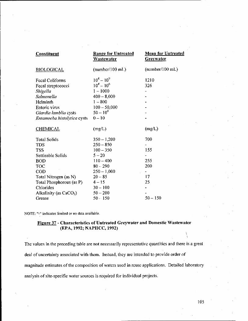
Constituent Ranee for Untreated Mean for Untreated Wastewater Grevwater
BIOLOGICAL (number/100 mL) (number/100 mL)
Fecal Coliforms 10'-10^ 1210 Fecal streptococci 10"-10^ 326 Shigella 1-1000 - Salmonella 400-8,000 -
Helminth 1-800 -
Enteric virus 100-50,000 -
Giardia lamblia cysts 50-10" - Entamoeba histolytica cysts 0-10 -
CHEMICAL (mg/L) (mg/L)
Total Solids 350-1,200 700 TDS 250-850 -
TSS 100-350 155 Settleable Solids 5-20 -
BOD 110-400 255 TOC 80-290 200 COD 250-1,000 - Total Nitrogen (as N) 20-85 17 Total Phosphorous (as P) 4-15 25 Chlorides 30-100 -
Alkalinity (as CaCOs) 50-200 - Grease 50-150 50-150
NOTE: "-" indicates limited or no data available.
Figure 37 - Characteristics of Untreated Greywater and Domestic Wastewater (EPA, 1992; NAPHCC, 1992)
The values in the preceding table are not necessarily representative quantities and there is a great
deal of uncertainty associated with them. Instead, they are intended to provide order of
magnitude estimates of the composition of waters used in reuse applications. Detailed laboratory
analysis of site-specific water sources is required for individual projects.
105
9.1.1.3. Rate of Release
Rate of release for a contaminant is typically measured in units of mass per time (i.e.
lb/day). Flow rate into a wastewater treatment plant (or greywater storage unit) is the primary
variable in determining contaminant release rate. Depending on the contaminant of concern,
Federal and state regulations require treatment based on peak or average flows. For example,
certain processes are based on peak hourly flows, while others are computed using annual
average flows. Further, some NPDES permits (such as for Nitrogen) are based on total yearly or
monthly release into the environment, rather than concentrations. Determination of the release
rate is the first step in quantifying the amount of contaminants in the environment and selecting
the appropriate treatment processes needed to reduce them to within regulatory standards.
9.1.2. Transport Assessment
Transport assessment involves identifying all possible media through which contaminants
travel and their biological, chemical, and physical interactions with those media and the
environment. The purpose of a transport assessment is to determine contaminant concentrations
in the air, food, water, or other media of concern at specific locations and times. Typically, this
is done using mathematical or computer models that have been developed to simulate natural or
manmade systems (Eisenberg, 2003; Fjeld and Compton, 1998).
When planning a water reuse project using secondary effluent, water quality data can be
obtained from the local municipality. Greywater must be evaluated on a case-by case basis to
obtain quality data. Using the recommended water quality guidelines described in sections 5
through 7 for the various reuse applications, the quality of the proposed water source must be
evaluated to determine if it meets these standards. For constituents that do not meet standards,
additional treatment will be required, as previously discussed. Historical data for treatment
106

efficiency, pilot tests, manual calculations, and computer simulations can all be used to estimate
the destruction of contaminants in a particular treatment scheme. For land treatment, interactions
with vegetation, soil, and groundwater must all be considered.
9.1.3. Exposure Assessment
Exposure assessment considers the various routes, rates, and timeframes within which
humans come in contact with contaminants. The purpose of an exposure assessment is to
determine the dose rate or total dose of a particular contaminant or set of contaminants. Dose
rate is typically expressed as milligrams of contaminant per kilogram of body mass per day
(mg/kg-day). Total (or integrated) dose is expressed as milligrams of contaminant per kilogram
of body mass (mg/kg).
There are three primary routes in which contaminants may enter the body. They include:
(1) inhalation, (2) ingestion, and (3) skin absorption. Inhalation involves breathing contaminants
through the nose or mouth. For example, breathing mists from cooling towers or golf course
sprinklers when standing in close proximity to one of these sources is an inhalation route.
Inhalation rate (i.e. breathing rate) varies by individual and is a function of age, weight, sex,
activity level, and physical fitness, among others. EPA recommends average breathing rates of
0.8 rc?l\\r for adults and 0.4 m^/hr for children at rest. Ingestion entails consumption of
contaminated materials in water, food, or soil. Adults typically consume between 0.3 to 3.8
L/day of water, whereas children drink about 0.5 to 0.8 L/day. Typically, water consumption as
a source for contaminant ingestion can be neglected when performing a water reuse risk
assessment, since reclaimed sources are required to be separated from potable supplies and
secured against public use. The next ingestion pathway is food consumption. Contaminant
ingestion from foods can be through indirect or direct contact with the contaminants. Indirect
107
contact involves eating animals or fish that previously consumed contaminated water or food.
This process is termed "biomagniflcation". An example of biomagnification is eating meat from
cows that grazed on contaminated grasses. Direct ingestion is consumption of contaminated
foodstuffs, such as fish from a contaminated pond or vegetables grown in contaminated soil.
Finally, soil ingestion must also be considered. This can result from unintended ingestion of soil
from homegrown vegetables, dust from handling food or other contaminated objects (i.e. golf
balls) without washing one's hands, and particulates trapped in the respiratory tract. Further,
children have been known to consume between 100 to 200 mg/day of soil. The final route of
exposure is skin absorption. This can involve being sprayed by a sprinkler emitting reclaimed
water, or mist from a vehicle or aircraft wash station, and many other possibilities. Depending
on the system used, frequency of contact with base residents, and types of contaminants present,
different routes of exposure will be more significant than others (Eisenberg, 2003; Fjeld and
Compton, 1998).
EPA typically uses two approaches for calculating dose rate for an individual or
population exposed to a contaminant. The approach depends on the type of effect the
contaminant is expected to induce. Certain contaminants produce deterministic effects, where
the severity of the effect is a function of dose. This means that below a particular dose, few or
no effects will be observed. As the dose increases, adverse effects such as irritation,
inflammation, burning, or others will be observed. For contaminants that produce stochastic
effects, the probability of the effect is a function of the dose. This means that above a given
dose, there is a certain probability that an effect will occur. The most common stochastic
contaminants are carcinogens. The general formula for calculating the dose rate (also called the
average daily dose) is as follows:
108
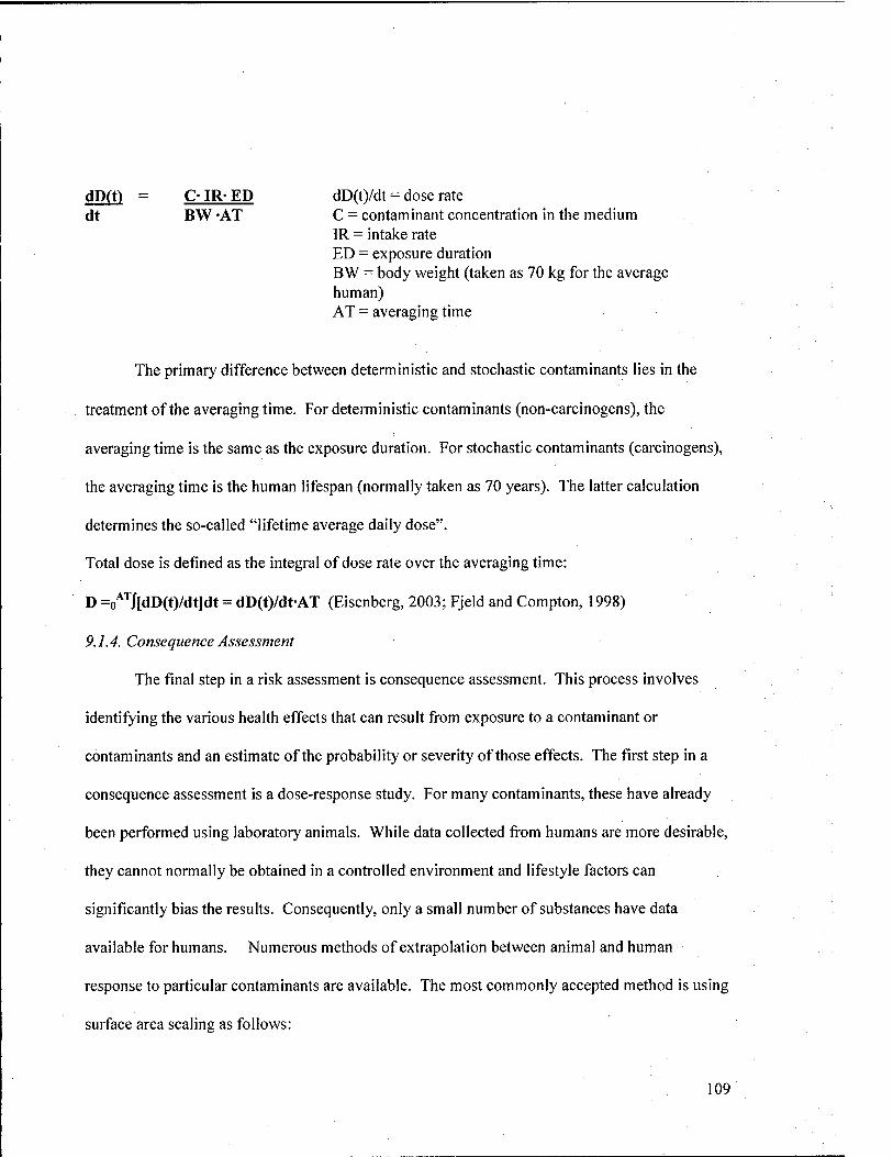
dD(t) = C- IR- ED dD(t)/dt = dose rate dt BW -AT C = contaminant concentration in the medium
IR = intake rate ED = exposure duration BW = body weight (taken as 70 kg for the average human) AT = averaging time
The primary difference between deterministic and stochastic contaminants lies in the
treatment of the averaging time. For deterministic contaminants (non-carcinogens), the
averaging time is the same as the exposure duration. For stochastic contaminants (carcinogens),
the averaging time is the human lifespan (normally taken as 70 years). The latter calculation
determines the so-called "lifetime average daily dose".
Total dose is defined as the integral of dose rate over the averaging time:
D =o'^^J[dD(t)/dt]dt = dD(t)/dt-AT (Eisenberg, 2003; Fjeld and Compton, 1998)
9.1.4. Consequence Assessment
The final step in a risk assessment is consequence assessment. This process involves
identifying the various health effects that can result from exposure to a contaminant or
contaminants and an estimate of the probability or severity of those effects. The first step in a
consequence assessment is a dose-response study. For many contaminants, these have already
been performed using laboratory animals. While data collected from humans are more desirable,
they cannot normally be obtained in a controlled environment and lifestyle factors can
significantly bias the results. Consequently, only a small number of substances have data
available for humans. Numerous methods of extrapolation between animal and human
response to particular contaminants are available. The most commonly accepted method is using
surface area scaling as follows:
109
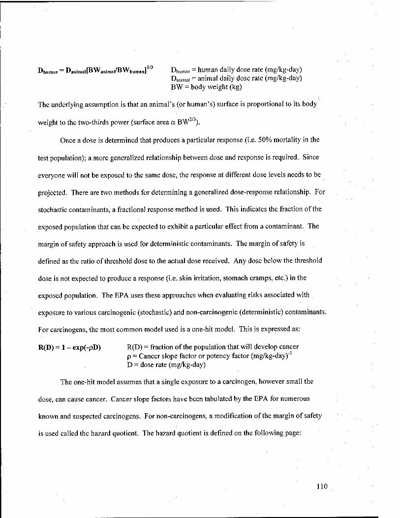
Dhuman = Da„in,ai[BWj,„imai/BWh„n,an]^ Dhuman = huHian daily dose rate (mg/kg-day) Danimai =" animal daily dose rate (mg/kg-day) BW = body weight (kg)
The underlying assumption is that an animal's (or human's) surface is proportional to its body
weight to the two-thirds power (surface area a BW ).
Once a dose is determined that produces a particular response (i.e. 50% mortality in the
test population); a more generalized relationship between dose and response is required. Since
everyone will not be exposed to the same dose, the response at different dose levels needs to be
projected. There are two methods for determining a generalized dose-response relationship. For
stochastic contaminants, a fractional response method is used. This indicates the fraction of the
exposed population that can be expected to exhibit a particular effect from a contaminant. The
margin of safety approach is used for deterministic contaminants. The margin of safety is
defined as the ratio of threshold dose to the actual dose received. Any dose below the threshold
dose is not expected to produce a response (i.e. skin irritation, stomach cramps, etc.) in the
exposed population. The EPA uses these approaches when evaluating risks associated with
exposure to various carcinogenic (stochastic) and non-carcinogenic (deterministic) contaminants.
For carcinogens, the most common model used is a one-hit model. This is expressed as:
R(D) = 1 - exp(-pD) R(D) = fraction of the population that will develop cancer -1 p = Cancer slope factor or potency factor (mg/kg-day)
D = dose rate (mg/kg-day)
The one-hit model assumes that a single exposure to a carcinogen, however small the
dose, can cause cancer. Cancer slope factors have been tabulated by the EPA for numerous
known and suspected carcinogens. For non-carcinogens, a modification of the margin of safety
is used called the hazard quotient. The hazard quotient is defined on the following page:
110
HQ = D/RfD HQ = hazard quotient D = dose rate (mg/kg-day) RfD = reference dose (mg/kg-day)
EPA defines the reference dose as the dose that does not produce any significant effects in the
most sensitive member of a population over a lifetime of exposure. EPA has recorded reference
doses for many non-carcinogens.
If multiple contaminants are involved, the one-hit model is modified for carcinogens as
follows:
R(D) = l-exp(-i:pD)
For non-carcinogens, the hazard index is used. The hazard index is defined as the sum of the
hazard quotients for each contaminant. If the hazard index is less than 1, then the risk associated
with a particular project is normally deemed acceptable. Otherwise, further analysis is required
(Eisenberg, 2003; Fjeld and Compton, 1998).
9.2. COST
A significant factor in the decision of whether to implement a water reuse project is the
net cost incurred by the Government. The standard approach used to evaluate the economic
feasibility of a water conservation initiative is a Life Cycle Cost Analysis. In order to obtain
Federal funding for a water conservation project, it must have an acceptable savings-to-
investment ratio (i.e. benefit-to-cost ratio) and no more than a 10-year payback. Consequently,
not only must a project's long-term economic yield (i.e. cost savings) exceed the start up and
operating costs, but a net return must be realized within 10 years. A Life Cycle Cost Analysis
and is required for all projects submitted to the Naval Facilities Engineering Command
(NAVFAC) for approval and is used to calculate the payback period. The NAVFAC handbook.
111
P-442 contains detailed procedures for performing a Life Cycle Cost Analysis (NFESC, 1993).
The issue of cost is addressed more thoroughly in Sections 10 and 11.
9.3. PUBLIC OPINION
In the context of this paper, the "public" includes station and tenant personnel, base
residents, and other individuals that may be affected by potential water reuse projects (i.e. golfers
using a military course that is open to the public). It is extremely important to consider public
opinion when planning a reuse project for two reasons. First, personnel must be made aware of
the potential risks and precautions associated with water reuse. Second, if a project receives
public backing, it will be more easily implemented and stands a higher chance of long-term
success.
EPA has promulgated a variety of surveys regarding water reuse alternatives over the
past 30 years. Results have generally indicated a positive response (80% or higher not opposed)
to most non-potable water reuse applications. Surveys taken in populations where water reuse
projects were being imminently considered indicated that the primary concerns, in order of
importance, are as follows:
• Ability ofa project to conserve water
• Environmental enhancements achieved
• Protection of public health
• Cost of treatment
• Cost of distribution
112
As a result of years of public opinion studies, EPA recommends that planners consider
the following items when establishing a water reuse program:
• Expected degree of human contact with reclaimed water sources
• Public health protection
• Conservation and environmental benefits
• Treatment and distribution costs
It is equally important to make the public aware of the need for and reliability of water reuse
applications. This includes:
• Increasing awareness of supply problems and how reclaimed water can be effectively
used to meet demand
• Public understanding of the quality, treatment, and uses of reclaimed water
• Confidence in water managers and available technology to provide safe and effective
treatment
• Minimal risk of accidental exposure to toxins or pathogens in the water above accepted
standards
A number of tools can be used to encourage participation and foster public cooperation
during the planning and execution of water reuse projects. Educational and informational
materials such as newsletters, presentations, infomercials, brochures, and conferences can be
used to raise the knowledge and confidence levels of affected personnel. Surveys, briefings, e-
mail or phone hotlines, and public hearings can all be used to solicit comments and reactions
from the base population, address concerns, and allay fears or misconceptions that individuals
may have. Finally, workshops, task forces, interviews, study groups can be convened to
maintain a constant dialogue between the public and planners every step of the way. The
113

methods and extent of public participation will vary with every reuse project and every
installation. However, any or all of these tools can be used to ensure the public is informed and
on-board with water reuse initiatives (EPA, 1992).
14
10. ECONOMIC CONSIDERATIONS
Planners must consider a number of economic factors when attempting to fund and
execute a water reuse project. Economics will often dictate the size, extent, and overall viability
of a proposed project. Primary considerations include: (1) benefits, (2) reliability, (3) timing,
and (4) optimization. Each is described below.
10.1. BENEFITS
The expected benefits of implementing a water reuse project are likely the most
important consideration in an economic analysis. If a project is not cost effective, its chances for
gaining approval and funding are limited, at best. While the fundamental goal of the Navy Water
Conservation Program is to reduce water consumption on U.S. Naval facilities, the underlying
impetus is cost reduction. If a project does not save the Government money, it will not succeed.
That said, planners must clearly define and forecast the expected cost savings due to reduction in
potable water demand, wastewater disposal costs, or both.
A number of scenarios exist where considerable economic gains can be made through
water reuse. In water deficient areas (i.e. Western U.S.), decreased requirements for potable
water will likely lead to significant cost savings. In many of these areas, the cost and associated
restrictions for obtaining potable supplies often stifles growth and expansion. For example, it is
nearly impossible to build golf courses in states like Arizona and California without a water
reuse irrigation system. Another benefit holds in both water deficient and water rich areas. Due
to population growth or stricter regulatory standards, upgrades or enlargement of wastewater
treatment plants may be delayed if a portion of water is sent for reuse, instead of being
discharged. Similarly, if present water sources are not adequate to meet growth rates and
115
demand, water reuse can be economically attractive. Water reuse options that result in low or no
cost to the end user are also easier to implement. For example, providing tenant commands, such
as MWR, with free irrigation water is often a selling point for a reuse project. Not only will their
expenses be reduced, but also the base can ensure future availability of potable supplies for
higher-priority or mission-oriented uses (Leeds, Hill, and Jewitt, 1971).
10.2. RELIABILITY
Reliability of the proposed project is another important consideration. The project must
have sufficient storage, treatment redundancies, emergency power, and other features to ensure
uninterrupted delivery of water. In water deficient areas, this is often less of an issue, due to the
relative abundance of treated wastewater as compared to potable water. In water rich areas with
excess capacity, however, reuse may be justified if costs can be shown to be less than the
operating costs of potable treatment plants or existing wastewater treatment plants over the long
term (Leeds, Hill, and Jewitt, 1971).
10.3. TIMING
Proper timing of a water reuse project is critical. To gain support, imminent or
foreseeable problems with current operations or water supplies must be apparent. Examples
include when water demands approach the limits of the existing system, increased municipal
effluent quality requirements, or wastewater flows approaching system capacity. Another option
is when new potential reclaimed water users decide to locate in the area, such as a new tenant
command on the base with high projected water requirements. It is important that projects come
116
on line before or at the time when demand exceeds supply to realize the highest economic gain
(Leeds, Hill, and Jewitt, 1971).
10.4. OPTIMIZATION
Optimization is the process of determining the appropriate size, extent, and configuration
of a water reuse project based on associated costs for each option considered. In order to do this,
a comparison must be made for marginal costs of serving potential users with reclaimed water
versus potable supply. Marginal costs are defined as the average incremental costs required to
meet water demand. This must include additional costs incurred due to using poorer quality
water. For example, operating problems, additional treatment requirements, and increased
maintenance may all result from water reuse. The costs associated with each of these items must
be considered when comparing to operating and maintenance costs for potable use. If it is more
economical to use potable supplies, a particular option becomes less attractive, and in many
cases is ruled out (Leeds, Hill, and Jewitt, 1971).
117
11. IMPLEMENTING WATER REUSE PROJECTS
There are four key steps for successful implementation of a proposed water reuse project.
After the scope and cost estimates have been developed, the appropriate documentation must be
prepared for submission to NAVFAC and funding must be obtained. As previously discussed,
public education is a critical factor in a water reuse project's success. Education initiatives
should begin in the planning process and continue well after the project has been executed.
Finally, impacts of the water reuse project (cost savings, problems, etc.) should be monitored to
determine if the system is operating as planned. If not, adjustments may need to be made to
realize its full benefits. Each of the steps for project implementation is described below:
11.1.SUBMITTALS
Once a project has been planned, it is important to begin the submittal process as soon as
possible. Commands should allow at least six to eight weeks for approval by NAVFAC and
another two to three months to receive funding. The project programming process is
summarized in Figure 38 on the following page.
118
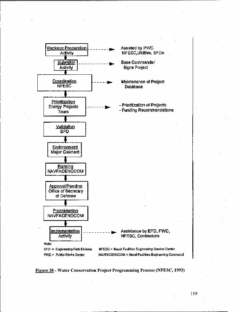
Package Preparation Adivity
Activity
Coordination NFESC
I Prioritization
Energy Projects Team
I Validation
EFD
I EndonserriCTit
Major Ciaiinant
I Ranking
NAVFACENGCOM
I Approval^Funding Office of Secretary
of Defense
I ProcrramiminQ
NAVFACEI^JGCOM
I Implementation
Activity
Note;
EFO = Englnaefng R*W DivJEion
PWO?= PuWl5VVb[k?C«nter
Assisted by PV^, NFE£C,Utlliti95, EFDs
Base Ccmmander Sign$ Project
Maintenance of Project Database
Prioritization of Projects Funding Recomin&ndafions
^^ Assistance by EFD, PWC, NFESC, Contractors
NF£5C= Navel FadlltJBS Engineering Saivic^ Center
HAVFACENGCOM = M»V8l FscJlitws Etvglneeiing CommarnJ
Figure 38 - Water Conservation Project Programming Process (NFESC, 1993)
119
In order for a project to be approved and funded, a Water Project Package must be
developed by the originating activity. There are muUiple parts of the package that must be
prepared in accordance with NAVFAC guidelines. Each part is briefly described below. The
Navy Energy Manager's Handbook and the Navy Water Conservation Guide for Shore Activities
should be consulted for more detailed procedures when preparing a Water Project Package.
• Part 1 - Cover Letter, Summary Sheet and List of Attachments: The cover letter should be
addressed from the activity commanding officer to Naval Facilities Engineering Service Center
(Code 22) with a copy to the Engineering Field Division (EFD) and Major Claimant. The
summary sheet includes a brief summary of the contents of the package and financial
information from the Life Cycle Cost Analysis. Finally, a list of attachments is included after the
summary sheet.
• Part 2 -DP Form 1391: The DD Form 1391 is the principal programming document used
to initiate and track all Department of Defense projects. Detailed guidance for completing the
DD Form 1391 can be found in NAVFACINST 11010.44E, the Shore Facilities Planning Guide
and the Navy Water Conservation Guide for Shore Activities.
• Part 3 - Facility Study: A DD Form 1391 c is used to complete the Facility Study. It
includes 32 parts and should make reference to the Life Cycle Cost Analysis and categorical
exclusions statement (Part 4). NAVFACINST 11010.44E provides specific guidance on
completing the DD Form 1391 c.
• Part 4 - Life Cycle Cost (LCQ: The LCC Analysis performed for the project is included
as Part 4 of the Water Project Package. The NAVFAC handbook, P-442 Economic Analysis
Handbook is the standard reference for this process. NFESC has created a spreadsheet in
120
Microsoft Excel to make the Life Cycle Cost Analysis easier and standardize submissions.
Requests for an electronic copy of the spreadsheet should be made to NFESC (Code 221).
• Part 5 - Assumptions/ Categorical Exclusion Attachments: Any assumptions used when
making technical calculations need to be listed in Part 5. Categorical exclusion statements are
prepared for projects where an EIS is not required.
• Part 6 - Supporting Savings Calculations/Cost Estimates/ Audit Information Attachments:
Part 6 should include relevant calculations, especially those used in the Life Cycle Cost Analysis.
Other pertinent information from studies or audits that were conducted should also be included.
• Part 7 - Other Data and Information: Other relevant information not incorporated in Parts
1 through 6 should be included in Part 7. This includes salvage quotes, utility rate information,
rebates, meteorological data, and other related information.
• Part 8 - Site Plan/ Building List: Maps and drawings, location lists, and other helpful site
information should be included in Part 8.
• Part 9 - Points of Contact: Key points of contact for all aspects of the project should be
included, along with the project developer and project recipient.
• Part 10 - References: Reference materials used to prepare the project package should be
listed in Part 10.
The deadline for submitting project packages is March 30th. If current fiscal year funding is
desired, the Water Project Package should be submitted no later than mid February. Key
responsibilities of each of the organizations in the submittal chain are indicated on the following
page:
121
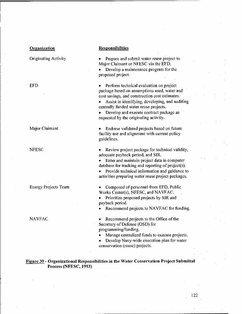
Organization
Originating Activity
EFD
Major Claimant
NFESC
Energy Projects Team
NAVFAC
Responsibilities
• Prepare and submit water reuse project to Major Claimant or NFESC via the EFD. • Develop a maintenance program for the proposed project.
• Perform technical evaluation on project package based on assumptions used, water and cost savings, and construction cost estimates. • Assist in identifying, developing, and auditing centrally funded water reuse projects. • Develop and execute contract package as requested by the originating activity.
• Endorse validated projects based on future facility use and alignment with current policy guidelines.
• Review project package for technical validity, adequate payback period, and SIR. • Enter and maintain project data in computer database for tracking and reporting of project(s). • Provide technical information and guidance to activities preparing water reuse project packages.
• Composed of personnel from EFD, Public Works Center(s), NFESC, and NAVFAC. • Prioritize proposed projects by SIR and payback period. • Recommend projects to NAVFAC for funding.
• Recommend projects to the Office of the Secretary of Defense (OSD) for programming/funding. • Manage centralized funds to execute projects. • Develop Navy-wide execution plan for water conservation (reuse) projects.
Figure 39 - Organizational Responsibilities in the Water Conservation Project Submittal Process (NFESC, 1993)
122
11.2. FUNDING
Large water reuse projects can be centrally funded using two funding programs managed
by NAVFAC. They are the Energy Conservation Investment Program (EClP) and the Federal
Energy Management Program (FEMP). Large projects are defined as those costing more than
$50,000. Projects costing less than this amount must be funded by the individual activity and are
considered "low cost/no cost" projects. All Navy activities are eligible to use ECIP funds for
construction-type projects estimated at $300,000 or more. ECIP projects must also require more
than one year to execute and a substantial amount of design. FEMP funding is available for
eligible projects that have not been funded by either ECIP or Major Claimant funds. Many water
reuse projects will be covered under FEMP, since they are typically not construction in scope.
Rather, they are often repair, maintenance, or equipment installation type projects.
Projects for Family Housing (FH) and Bureau of Medicine (BUMED) cannot be funded
using ECIP or FEMP money. These projects can still be implemented, but are funded from
separate accounts. For FH, water conservation retrofits can be programmed into the Whole
House Repair Program and performed as part of other major renovations to reduce downtime of
housing units.
In addition to being greater than $50,000 in scope, projects must also have an acceptable
SIR, a payback period of 10 years or less, meet Department of Defense funding obligation
schedules, and reduce potable water consumption to be eligible for ECIP or FEMP funds. If
FEMP funds are selected, they must be obligated in the same fiscal year in which approved. It
is possible to combine multiple smaller projects into a larger project in order to meet central
funding requirements. However, the projects must all have a common thread. Individual
projects can all be within the same facility or at muhiple facilities (NFESC, 1993).
123
1 ] .3. BASE-WIDE EDUCATION
As described in Section 9.3, public opinion and involvement is a critical factor in a water
reuse project's success. In order to ensure newly installed technologies are properly operated and
maintained, and to prevent undue health risks to the affected population, base-wide education
measures must be taken before, during, and after the project has been implemented. Many of the
same approaches described in Section 9.3 can be used for base-wide education. Visual aids, such
as posters, signs, flyers, videos, and demonstrations are helpful in conveying pertinent
information about a water reuse system to large audiences. Facility occupants and maintenance
staffs must be trained on the correct operating procedures and safeguards associated with water
reuse measures. If there is a perception that the new system won't work as well, it is important to
emphasize that with proper operation and maintenance, the same level and quality of service can
be expected as with potable water (NFESC, 1993).
11.4. MONITORING RESULTS
Periodic monitoring of the reuse measures implemented on a base is required to
determine if they are working and to identify problems. The following actions should be
included in a monitoring program (NFESC, 1993):
• Periodically check water usage for each device or system using reclaimed water. Results
should be compared to pre-installation consumption.
• Evaluate trends in water and sewer bills. If water reuse measures are working properly,
bills should reflect decreases in overall consumption and costs.
• Ensure that maintenance personnel are assigned to monitor and repair installed
equipment, as needed.
124
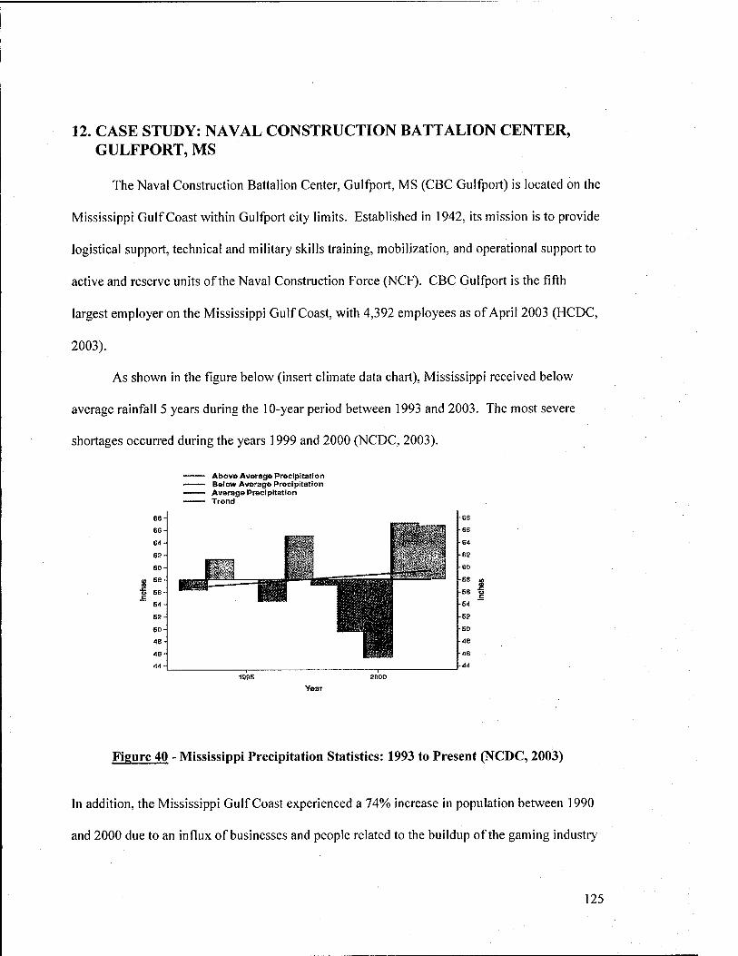
12. CASE STUDY: NAVAL CONSTRUCTION BATTALION CENTER, GULFPORT, MS
The Naval Construction Battalion Center, Gulfport, MS (CBC Gulfport) is located on the
Mississippi Gulf Coast within Gulfport city limits. Established in 1942, its mission is to provide
logistical support, technical and military skills training, mobilization, and operational support to
active and reserve units of the Naval Construction Force (NCF). CBC Gulfport is the fifth
largest employer on the Mississippi Gulf Coast, with 4,392 employees as of April 2003 (HCDC,
2003).
As shown in the figure below (insert climate data chart), Mississippi received below
average rainfall 5 years during the 10-year period between 1993 and 2003. The most severe
shortages occurred during the years 1999 and 2000 (NCDC, 2003).
68
6S
E-l
62
60
S SB
o 66
52
60
Ae
Ae
A«
Abov» Average Prectpttation Below Average Precipitation Average Precipitation Trend
68
68
-64
62
60
E8 tl> a
56 o
54
52
SO
-48
-46
-44
Figure 40 - Mississippi Precipitation Statistics: 1993 to Present (NCDC, 2003)
In addition, the Mississippi Gulf Coast experienced a 74% increase in population between 1990
and 2000 due to an influx of businesses and people related to the buildup of the gaming industry
125
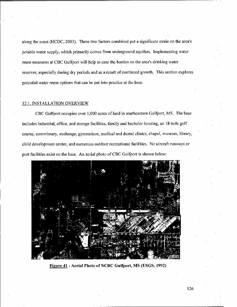
along the coast (HCDC, 2003). These two factors combined put a significant strain on the area's
potable water supply, which primarily comes from underground aquifers. Implementing water
reuse measures at CBC Gulfport will help to ease the burden on the area's drinking water
reserves, especially during dry periods and as a result of continued growth. This section explores
potential water reuse options that can be put into practice at the base.
12.1. INSTALLATION OVERVIEW
CBC Gulfport occupies over 1,000 acres of land in southeastern Gulfport, MS. The base
includes industrial, office, and storage facilities, family and bachelor housing, an 18-hole golf
course, commissary, exchange, gymnasium, medical and dental clinics, chapel, museum, library,
child development center, and numerous outdoor recreational facilities. No aircraft runways or
port facilities exist on the base. An aerial photo of CBC Gulfport is shown below:
Figure 41 - Aerial Photo of NCBC Gulfport, MS (USGS, 1992)
126
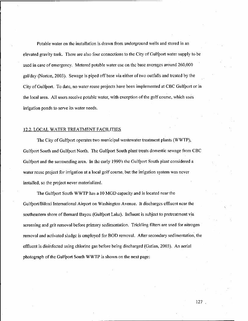
Potable water on the installation is drawn from underground wells and stored in an
elevated gravity tank. There are also four connections to the City of Gulfport water supply to be
used in case of emergency. Metered potable water use on the base averages around 260,000
gal/day (Norton, 2003). Sewage is piped off base via either of two outfalls and treated by the
City of Gulfport. To date, no water reuse projects have been implemented at CBC Gulfport or in
the local area. All users receive potable water, with exception of the golf course, which uses
irrigation ponds to serve its water needs.
12.2. LOCAL WATER TREATMENT FACILITIES
The City of Gulfport operates two municipal wastewater treatment plants (WWTP),
Gulfport South and Gulfport North. The Gulfport South plant treats domestic sewage from CBC
Gulfport and the surrounding area. In the early 1990's the Gulfport South plant considered a
water reuse project for irrigation at a local golf course, but the irrigation system was never
installed, so the project never materialized.
The Gulfport South WWTP has a 10 MGD capacity and is located near the
Gulfport/Biloxi International Airport on Washington Avenue. It discharges effluent near the
southeastern shore of Bernard Bayou (Gulfport Lake). Influent is subject to pretreatment via
screening and grit removal before primary sedimentation. Trickling filters are used for nitrogen
removal and activated sludge is employed for BOD removal. After secondary sedimentation, the
effluent is disinfected using chlorine gas before being discharged (Gatian, 2003). An aerial
photograph of the Gulfport South WWTP is shown on the next page:
127
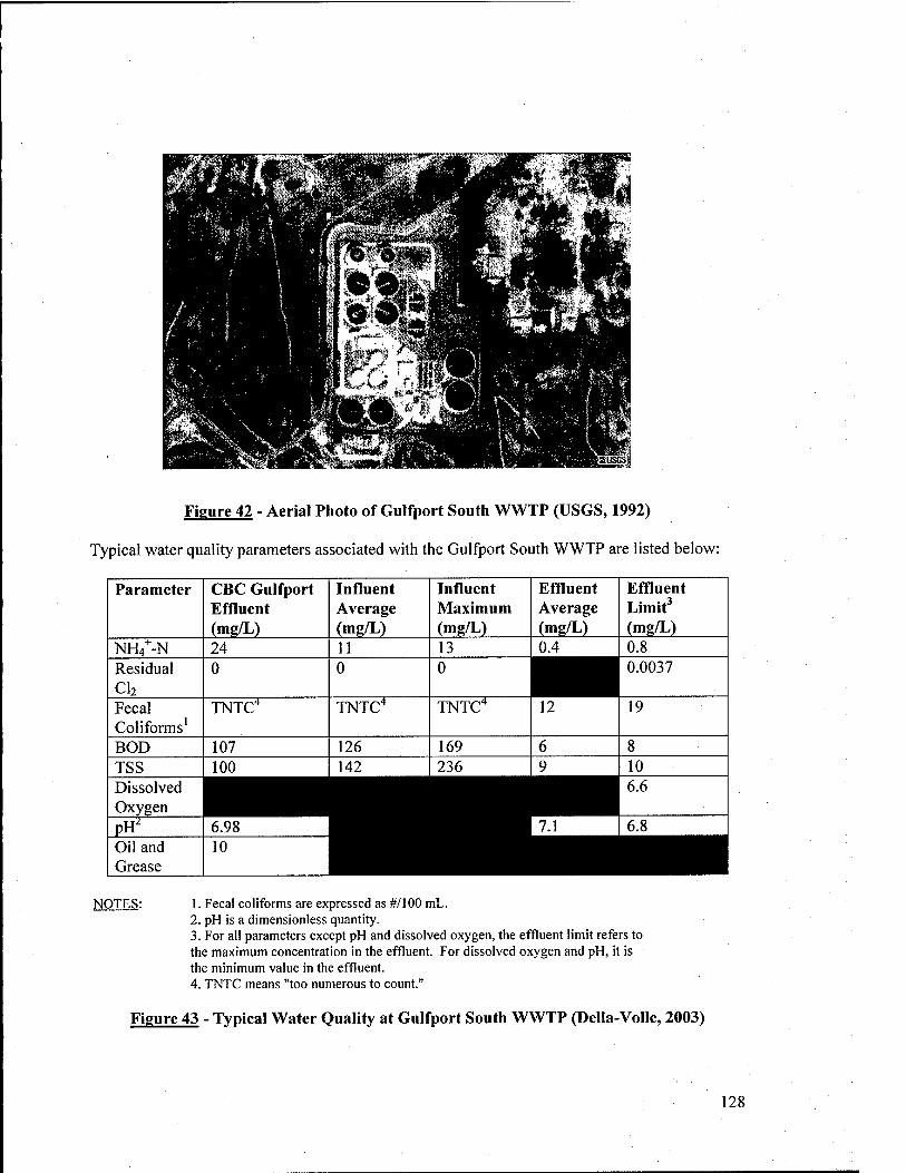
Figure 42 - Aerial Photo of Gulfport South WWTP (USGS, 1992)
Typical water quality parameters associated with the Gulfport South WWTP are listed below:
Parameter CBC Gulfport Effluent (mg/L)
Influent Average (mg/L)
Influent Maximum (mg/L)
Effluent Average (mg/L)
Effluent Limit^ (mg/L)
NH/-N 24 11 13 0.4 0.8 Residual CI2
0 0 0 0.0037
Fecal Coliforms'
TNTC^ TNTC* TNTC'' 12 19
BOD 107 126 169 6 8 TSS 100 142 236 9 10 Dissolved Oxygen ^m[ii ■ 6.6
PH^ 6.98 7.1 6.8 Oil and Grease
10 ^■H NOTES: I. Fecal coliforms are expressed as #/! 00 mL.
2. pH is a dimensionless quantity. 3. For all parameters except pH and dissolved oxygen, the effluent limit refers to the maximum concentration in the effluent. For dissolved oxygen and pH, it is the minimum value in the effluent. 4. TNTC means "too numerous to count."
Figure 43 - Typical Water Quality at Gulfport South WWTP (Della-Volle, 2003)
128
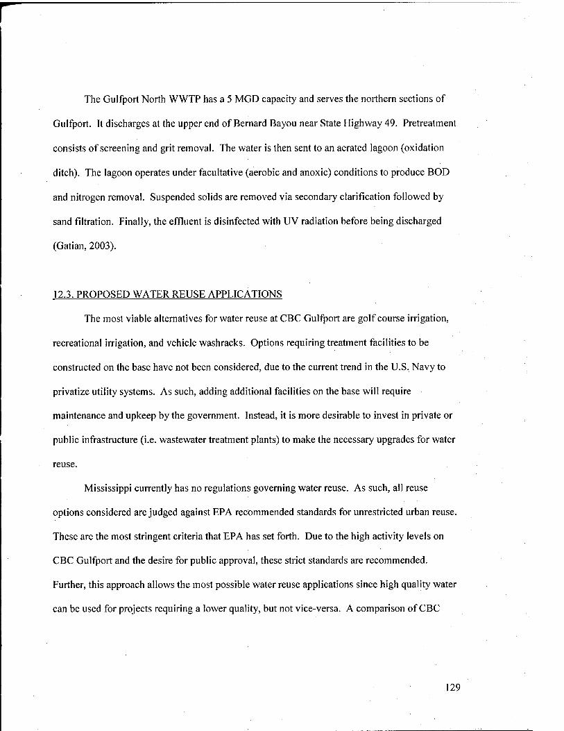
The Gulfport North WWTP has a 5 MGD capacity and serves the northern sections of
Gulfport. It discharges at the upper end of Bernard Bayou near State Highway 49. Pretreatment
consists of screening and grit removal. The water is then sent to an aerated lagoon (oxidation
ditch). The lagoon operates under facultative (aerobic and anoxic) conditions to produce BOD
and nitrogen removal. Suspended solids are removed via secondary clarification followed by
sand filtration. Finally, the effluent is disinfected with UV radiation before being discharged
(Gatian, 2003).
12.3. PROPOSED WATER REUSE APPLICATIONS
The most viable alternatives for water reuse at CBC Gulfport are golf course irrigation,
recreational irrigation, and vehicle washracks. Options requiring treatment facilities to be
constructed on the base have not been considered, due to the current trend in the U.S. Navy to
privatize utility systems. As such, adding additional facilities on the base will require
maintenance and upkeep by the government. Instead, it is more desirable to invest in private or
public infrastructure (i.e. wastewater treatment plants) to make the necessary upgrades for water
reuse.
Mississippi currently has no regulations governing water reuse. As such, all reuse
options considered are judged against EPA recommended standards for unrestricted urban reuse.
These are the most stringent criteria that EPA has set forth. Due to the high activity levels on
CBC Gulfport and the desire for public approval, these strict standards are recommended.
Further, this approach allows the most possible water reuse applications since high quality water
can be used for projects requiring a lower quality, but not vice-versa. A comparison of CBC
129
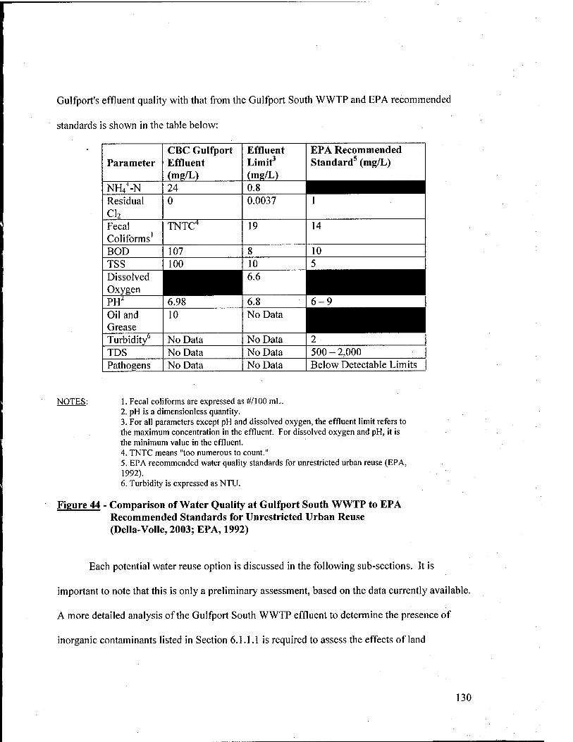
Gulfport's effluent quality with that from the Gulfport South WWTP and EPA recommended
standards is shown in the table below:
Parameter CBC Gulfport Effluent (mg/L)
Effluent Limit' (mg/L)
EPA Recommended Standard^ (mg/L)
NH/-N 24 Residual CI2
0 0.0037 1
Fecal Coliforms'
TNTC" 19 14
BOD 107 8 10 TSS 100 10 5
Oxygen ^^^^^^^^^| ^^^^^^^^^^^^^^| PH' 6.98 6.8 6-9 1 Oil and Grease
10 No Data ^^^^^^^^^^^H
Turbidity" No Data No Data 2 TDS No Data No Data 500-2,000 Pathogens No Data No Data Below Detectable Limits
NOTES: 1. Fecal coliforms are expressed as #/] 00 mL. 2. pH is a dimensionless quantity. 3. For all parameters except pH and dissolved oxygen, the effluent limit refers to the maximum concentration in the effluent. For dissolved oxygen and pH, it is the minimum value in the effluent. 4. TNTC means "too numerous to count." 5. EPA recommended water quality standards for unrestricted urban reuse (EPA, 1992). 6. Turbidity is expressed as NTU.
Figure 44 - Comparison of Water Quality at Gulfport South WWTP to EPA Recommended Standards for Unrestricted Urban Reuse (Della-Volle, 2003; EPA, 1992)
Each potential water reuse option is discussed in the following sub-sections. It is
important to note that this is only a preliminary assessment, based on the data currently available.
A more detailed analysis of the Gulfport South WWTP effluent to determine the presence of
inorganic contaminants listed in Section 6.1.1.1 is required to assess the effects of land
130
application of reclaimed water. Other issues to be considered are indicated in the ensuing
discussions.
12.3.1. Golf Course Irrigation
The Pine Bayou Golf Course currently operates two manmade irrigation ponds, one for
the front nine holes, and the other for the back nine holes. The front nine holes and their
irrigation system were constructed in 1975. In 1998, the base added the back nine holes and the
second irrigation pond. Appendices III and IV at the end of this report are the as-built irrigation
systems for the front and back nine holes, respectively. All greens and fairways are planted with
Bermuda grass. The overall golf course layout is pictured below:
Figure 45 - Pine Bayou Golf Course (PBGC, 2003)
During the drought years of 1999 and 2000, the golf course experienced substantial
difficulties maintaining adequate storage in their irrigation ponds. This was due both to above-
131
average irrigation requirements and seepage losses from the ponds, which are not lined. In
wetter years, the existing irrigation system had provided adequate water capacity. The golf
course management approached the Public Works Department to install small potable water
backup lines to feed the wet wells from which irrigation water was drawn. However, as the
drought wore on, it became evident that the current system might not meet demand. It was at
this point that the need for additional contingency water sources and/or improvements to the
existing irrigation system became apparent.
Over the past 3 years, Mississippi has experienced higher than average precipitation,
which has eased the burden on the golf course irrigation system. However, if and when another
drought occurs, the base will be faced with the same dilemma over irrigation water shortages.
Instead of augmenting the irrigation system with potable water as before, a strategy using treated
secondary effluent from the Gulfport South WWTP should be considered. Secondary effluent
from the Gulfport South WWTP meets EPA recommended criteria for unrestricted urban reuse,
except for fecal coliforms, TSS, and chlorine residual. Fecal coliforms and TSS are slightly
above recommended limits, while chlorine residual is much too low. Since Bermuda grass is
considered tolerant to salinity in reclaimed wastewater, no additional treatment should be
required to prevent salinity-related growth problems.
The recommended treatment strategy is to install slow sand fihers following secondary
clarification at the plant. Further, addition of coagulants (alum or ferric chloride) to the
secondary clarifiers is recommended to increase suspended solids removal. This plan will also
remove many of the inorganic contaminants described in Section 6.1.1.1. Lime addition is not
recommended, due to high sludge generation and potential bicarbonate permeability problems.
Slow sand filtration will serve as a polishing step to remove smaller particulates that pass
132
through the sedimentation process. Additional chlorination will be required to maintain the
recommended 1 mg/L residual. However, chlorine can be toxic to fish living in the irrigation
ponds. Dechlorination using sulfur dioxide may be performed after sufficient contact time has
elapsed in order to meet disinfection requirements without maintaining a chlorine residual.
However, the Mississippi Department of Environmental Quality (MDEQ) should be consulted
before a dechlorination strategy is selected. Finally, if the above treatment strategy is
implemented, no setbacks should be required to prevent public contact. MDEQ should also be
consulted about this requirement.
The Gulfport South WWTP is approximately 7 miles northeast of CBC Gulfport. Water
can be piped from the treatment plant to the base and discharged to either or both of the irrigation
ponds on an as-needed basis. Flow controls and a booster station will be required at the
treatment plant. An NPDES permit will be required, since "contaminated" water is being
discharged into surface water body (the irrigation ponds), even if the pond water is of poorer
quality than the treated effluent. However, this strategy will reduce the quantity of effluent
discharged into Bernard Bayou by the treatment plant. Another benefit to using reclaimed
secondary effluent to augment the golf course irrigation ponds is that they can be used as storage
for other water reuse applications.
There are a host of other issues that must be considered if a water reuse project of this
nature is to be realized. First, it is crucial that the irrigation ponds be drained and coated with
impermeable liners to prevent continued water losses and potential groundwater contamination.
This should be included as part of the scope for any water reuse project at the golf course.
Further, laboratory studies using turf and soil samples should be done to measure the effects of
secondary effluent application. An environmental risk analysis should also be performed to
133
determine any potential adverse effects on human health or the environment and their potential
impacts. It is, however, anticipated that human health and environmental degradation risks
associated with water reuse for golf course irrigation will be negligible. Finally, due to the scope
of the project, it will likely exceed $50,000, and therefore be eligible to receive Federal funding.
As such, CBC Gulfport should strongly consider pursuing this or similar projects.
12.3.2. Recreational Field Irrigation
Another water reuse option at CBC Gulfport is to use reclaimed water for recreational
field irrigation. Numerous recreational fields exist on the base, which are regularly watered
during the summer season. Water demand from irrigating these fields alone is probably not
sufficient to justify a full-scale reuse project, but this application could easily be incorporated
into a system for providing reclaimed water to the golf course. Integrating these two projects
will have two benefits. First, the overall scope and cost of the combined project will almost
certainly exceed the $50,000 Federal funding cutoff Second, increasing the scope provides
additional justification to implement the project. Stated another way, increasing the demand for
reclaimed water will further reduce the amount of secondary effluent discharged into Bernard
Bayou and the quantity of potable water used on the base.
The easiest option would be to draw from one or both of the golf course irrigation ponds
to irrigate the recreational fields. This will require additional irrigation piping to be installed
from the storage ponds to the recreational fields to supply the sprinkler heads. Alternately, a
separate branch from the incoming water main could be constructed solely for recreational
irrigation uses instead of drawing from the ponds. The primary benefit of using the irrigation
storage ponds as a source of water, both for the recreational fields and the golf course, is that
demand varies by season and by the amount of rainfall received. Irrigation requirements are
134
largely dependent on the weather. In a wet year, little or no irrigation may be required, whereas
during a drought, fields may be watered daily.
Similar considerations to those for the golf course will have to be made when planning to
use reclaimed water for recreational field irrigation. Water quality guidelines and problems are
essentially the same. As before, a laboratory analysis of the effects of reclaimed water on the
grass and soil should be performed. Further, since recreational fields receive more traffic and
access is less controlled as compared to a golf course, the risks associated with human exposure
to contaminants will have to be closely studied. Golf courses typically irrigate at night or in the
early morning hours, so as not to interrupt play. However, the recreational fields are often
watered during the day. To minimize risk of exposure to reclaimed water, it may be prudent to
adopt a similar watering schedule to that which the golf course uses.
12.3.3. Vehicle Washracks
A number of vehicle washracks exist on the base, most of which are located in equipment
maintenance areas. The most practical option for implementing a water reuse scheme is to use
treated secondary municipal effluent from the Gulfport South WWTP. While an on-site
treatment and reclamation system could be constructed, the cost and space requirements may be
prohibitive, especially given the number of vehicles washed and frequency of washing. For a
larger base, especially one that services aircraft, an on-site system might be justified.
As indicated in Section 5.1, the primary concern when using secondary effluent is
pathogen and microorganism removal. A comparison of the recommended quality for vehicle
washracks, effluent from the Gulfport South WWTP and EPA recommended standards for
unrestricted urban reuse is shown on the following page:
135
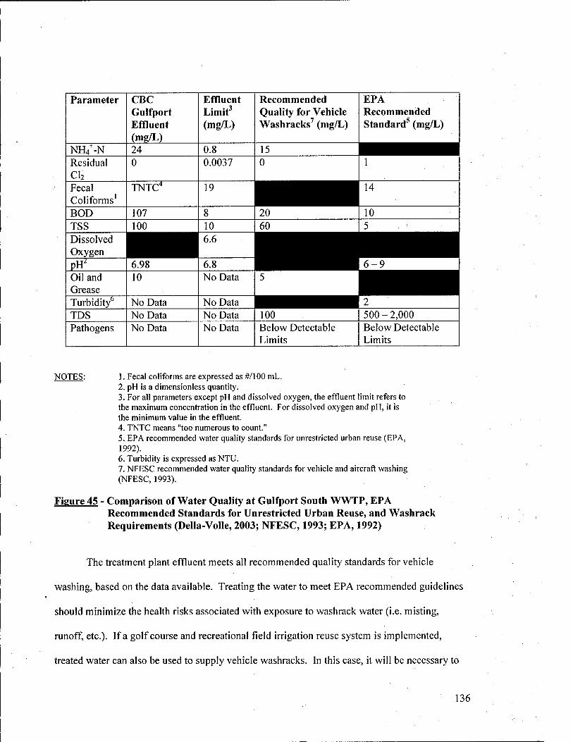
Parameter CBC Gulfport Effluent (mg/L)
Effluent Limit' (mg/L)
Recommended Quality for Vehicle Wash racks' (mg/L)
EPA Recommended Standard^ (mg/L)
NH4^-N 24 0.8 ^^^^^^^^1 Residual CI2
0 0.0037 0 1
Fecal Conforms'
TNTC* 19 14
BOD 107 8 20 10 TSS 100 10 60 5 Dissolved Oxygen ^^B 6.6
6-9 PH^ 6.98 6.8 Oil and Grease
10 No Data ^^^^^^^^1 Turbidity" No Data No Data 2 TDS No Data No Data 100 500 - 2,000 Pathogens No Data No Data Below Detectable
Limits Below Detectable Limits
NOTES: 1. Fecal coliforms are expressed as #/l 00 mL. 2. pH is a dimensionless quantity. 3. For all parameters except pH and dissolved oxygen, the effluent limit refers to the maximum concentration in the effluent. For dissolved oxygen and pH, it is the minimum value in the effluent. 4. TNTC means "too numerous to count." 5. EPA recommended water quality standards for unrestricted urban reuse (EPA, 1992). 6. Turbidity is expressed as NTU. 7. NFESC recommended water quality standards for vehicle and aircraft washing (NFESC, 1993).
Figure 45 - Comparison of Water Quality at Gulfport South WWTP, EPA Recommended Standards for Unrestricted Urban Reuse, and Washrack Requirements (Della-Volle, 2003; NFESC, 1993; EPA, 1992)
The treatment plant effluent meets all recommended quality standards for vehicle
washing, based on the data available. Treating the water to meet EPA recommended guidelines
should minimize the health risks associated with exposure to washrack water (i.e. misting,
runoff, etc.). If a golf course and recreational field irrigation reuse system is implemented,
treated water can also be used to supply vehicle washracks. In this case, it will be necessary to
136
create a separate storage tank for the washracks, instead of drawing directly from the irrigation
ponds to prevent quality problems. A portion of the incoming water from the treatment plant can
be diverted to storage for washrack use.
There are a number of issues surrounding water reuse for vehicle washracks, which must
be addressed. Unlike irrigation, where water is applied when the chance for human contact is
minimal (i.e. at night), vehicle washing takes place during the day when everyone is at work. As
such, the probability of exposure to reclaimed water is significantly higher. With proper
treatment, the risks to human health or the environment should be negligible. However, there
may be concerns voiced by those operating or working around the facilities since they are likely
to come into contact with the water at some point. Public education will be required to address
water quality issues, health concerns, and to assure workers that the system is in fact safe. These
issues will need to be considered in the risk analysis. Further, if enclosed storage is used, the
potential for regrowth exists. Constant circulation and flushing of the storage tank to prevent
stagnation is the most practical way to limit regrowth. Additional chlorination is not
recommended, since chlorine can damage vehicle surfaces.
137
13. CONCLUSIONS AND RECOMMENDATIONS
Planning for water reuse on Navy installations requires a good deal of research, design,
coordination, and foresight on the part of Navy facility and energy managers. The planning and
implementation process is normally measured in years, rather than months. Preparing the
required documentation, obtaining command, public, and local utility approval, and selecting the
optimum design can often be cumbersome. Major planning factors include legal and regulatory
considerations, treatment requirements, potential applications, risks to human health and the
environment, public opinion, and cost. Each of these issues must be considered in the decision
to implement a water reuse project. More exactly, they are used to balance the costs and benefits
of particular water reuse applications on a given installation. This paper attempts to guide Navy
facility and energy managers through the planning and implementation process by addressing
many of the key issues that need to be considered. However, it is by no means all-inclusive.
Each base has its own set of rules, operating conditions, and challenges. Further, each
community will view water reuse differently. Factors such as climate, local economy, size of the
Federal budget, and willingness to "think outside the box" will all impact the success of a
proposed reuse project. Planners must not only consider the issues discussed in this paper, but
rather put them into context as they apply to a particular installation.
Water reuse technologies have been in existence for almost 50 years. However, very few
Navy installations have implemented projects of this nature. Many large communities around
the U.S., along with the U.S. Army have been much more active in preparing guidance for and
executing water reuse projects. In order for the Navy to become more involved in water reuse
initiatives, a number of things need to happen. First, Navy facility and energy managers need to
be educated on water reuse. Much of the guidance prepared by the Navy Energy Management
138
and Water Conservation Programs only briefly addresses this option. As stated at the beginning
of this report, there is no comprehensive water reuse planning guidance for Navy facilities. As
such, managers have to rely on a select few individuals within NAVFAC who have experience
with these projects. This paper attempts to establish baseline guidance, but must first be
endorsed by NAVFAC before widespread distribution can occur. In the interim, training
sessions and seminars for facility and energy managers should be held to "get the word out"
about the benefits of water reuse. Second, public perceptions about water reuse need to be
evaluated. Many people are reluctant to accept reclaimed water as a viable alternative to potable
water. Concerns from command staff, base workforce, residents, and others who utilize affected
facilities should be addressed in public forums through literature and/or briefings to solicit input
and allay fears. Fostering positive opinions or even enthusiasm about water reuse can be critical
to any project's success. All Navy facilities should consider water reuse as a possible water
conservation measure. They should evaluate existing water conservation plans and facility
audits to determine where water reuse applications can be employed. This is especially true for
bases in the Western U.S. and other arid areas, where potable supplies are limited, expensive,
and highly contested.
139
APPENDIX I - GLOSSAR Y

GLOSSARY
• Alkalinity: Alkalinity is defined as the total concentration of hydroxide and carbonate
species in a wastewater sample as follows:
Alkalinity = [OH ] + [H2CO3] + [HCO3"] + 2IC03"^]
Alkalinity helps to buffer changes in the pH of a water due to acid addition. It is typically
reported as milligrams of calcium carbonate per liter (mg CaCOa/L).
• Biochemical Oxygen Demand (BOD): BOD refers to a test used to determine the
dissolved oxygen utilized by microorganisms in a water sample to oxidize organic matter.
Results from the BOD test are normally reported after a 5-day incubation period, since
approximately 60 to 70 percent of the dissolved oxygen in the sample has been used. A first
order decay relationship is used to estimate the BOD at equilibrium (called ultimate BOD) or at
other times (Metcalf and Eddy, 2003). In this report, BOD refers to the 5-day BOD or BOD5,
which is the standard parameter reported for most EPA and state regulatory requirements.
• Blackwater: Water that is discharged from toilets, urinals, dishwashers, kitchen sinks, and
similar appliances. It contains food, human wastes, and other organic matter (NFESC, 1993).
• Chemical Oxygen Demand (COD): The COD test is used to determine the organic
content of a wastewater sample. A strong oxidizing agent (normally potassium dichromate
(K2Cr207) is used to oxidize the organic matter and the equivalent amount of oxygen required is
calculated (Metcalf and Eddy, 2003).
• Greywater: Greywater includes water discharged from bathroom sinks, washing
machines, and showers in a residential or commercial building. Primary contaminants include
dirt, soap, and detergents (NFESC, 1993).
• Reclaimed Water: Water that is treated before reuse. Most water reuse applications use
reclaimed water (NFESC, 1993).
• Recycled Water: Water that is reused with little or no treatment (NFESC, 1993).
• Secondary Municipal Effluent: Secondary municipal effluent is domestic wastewater that
has been treated to remove solids, organic matter, nutrients, and pathogens to meet state or
federal permit requirements for discharge to surface water bodies. Treatment typically includes
pre-treatment, primary sedimentation, aerobic biological treatment, secondary sedimentation, and
disinfection. Secondary municipal effluent is also referred to as secondary effluent.
• Total Dissolved Solids (TDS): Total dissolved solids calculated as the difference
between total solids (measured in a laboratory as the residue in a dish after evaporation at 105°C)
and total suspended solids (see definition for TSS). Technically this calculation includes both
dissolved and colloidal solids, but the latter cannot easily be removed without additional
treatment (Metcalf and Eddy, 2003).
• Total Organic Carbon (TOO: Total Organic Carbon is a measure of the quantity of
organic matter present in a wastewater sample. It is analyzed by burning a sample in a furnace
and measuring the carbon dioxide produced from combustion (Metcalf and Eddy, 2003).
• Total Suspended Solids (TSS): Total suspended solids are measured in a laboratory using
an Imhoff Cone followed by a Whatman GF/C filter with a pore size of 1.2 |Lim. A wastewater
sample is placed in the Imhoff Cone for 60 minutes. The solids collected at the bottom of the
cone are termed "settleable solids" and are an estimate of the sludge removed by primary
sedimentation. The sample is then filtered using the Whatman GF/C apparatus. After
evaporation at 105°C, the residue on the filter is measured and classified as TSS (Metcalf and
Eddy, 2003).

• Turbidity: Turbidity is a measure of a water's ability to transmit light. The presence of
suspended matter will reduce light transmission and make the water look more opaque.
Turbidity is typically used as an indicator of suspended solids content in secondary municipal
effluent (Metcalf and Eddy, 2003).
• Water Reuse: Water reuse refers to use of secondary municipal effluent, greywater, or
other non-potable sources that have been used one or more times for a particular process or
application. Water reuse is typically done in place of using fresh potable water to meet process
needs.
APPENDIX II - EPA RECOMMENDED
GUIDELINES FOR WATER REUSE
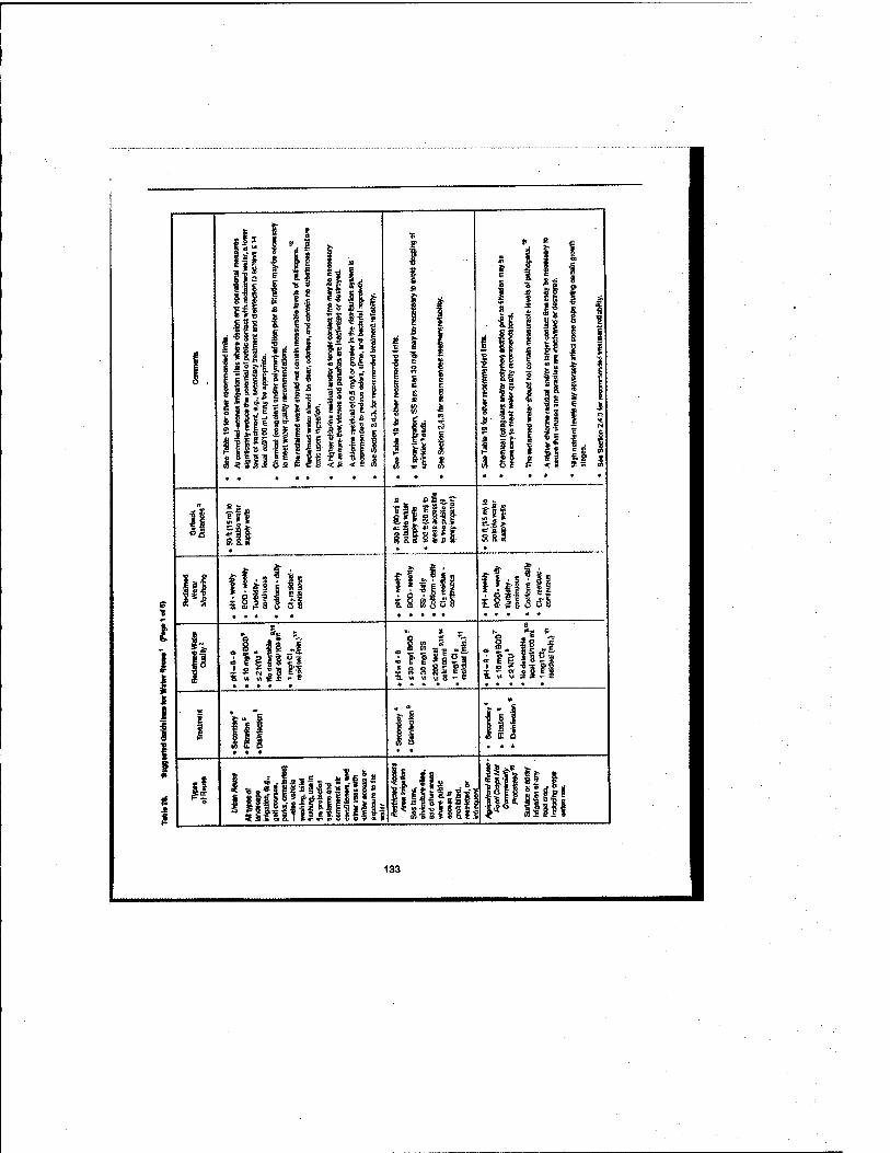
i 1 « s
s-S
il
IIIIJI
PJ ■S3' t3:g"B
*^ 5 lE *= £ ? ^
III
f
mill ,lill
kffliliiiiii
£8 8358
11 s a 2 » " «*s "a. w w V! 8 un
ll
it Ah llilll]
ig.li
*■! E s I 5 -fi « * I
Awl
4 f nil i vi " 5;
133
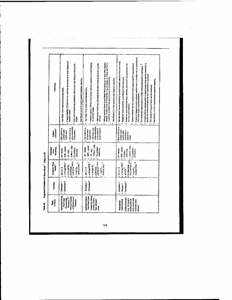
I I I £ r s g £ 2
s
I li
I II
t i
I I
Is f 8
sll ail i
K a gfllll
• 8 ' I 11 75. CD o^ V (;) a
i ?l i| = $ ■ 3 ^ 1 S I 5*1 6 B S ? O -S I I s I £ S 5 E Sol
y •« " 8 - e
le 1^ I 8 S5
— g
134
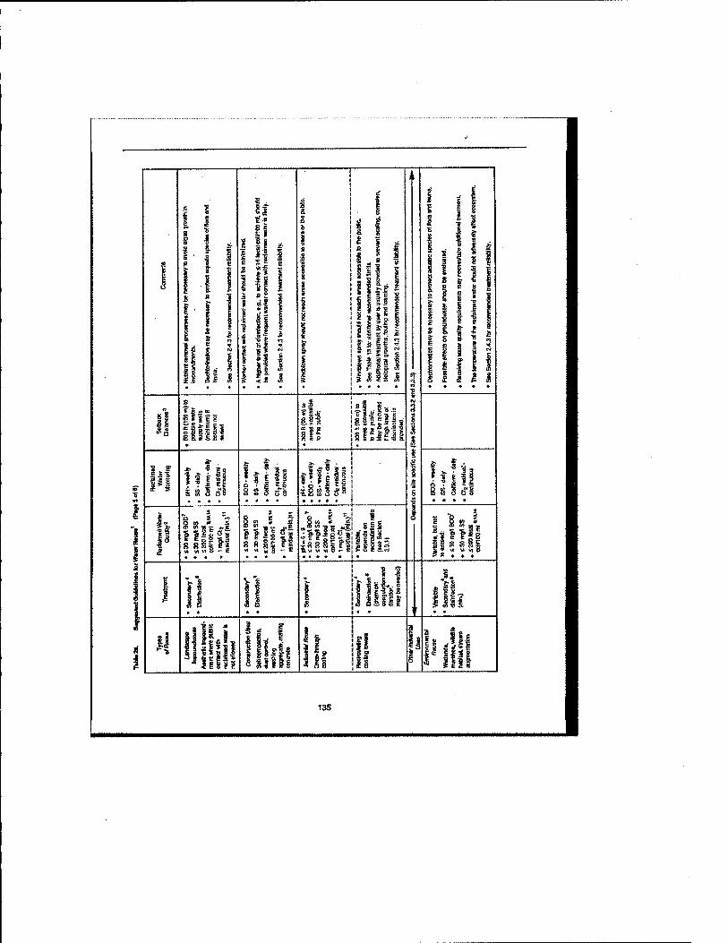
III
■s I ii 8! 8 oi
5 ^_
VI w a
5 8
llllfl
8 5B
III 51
I
135
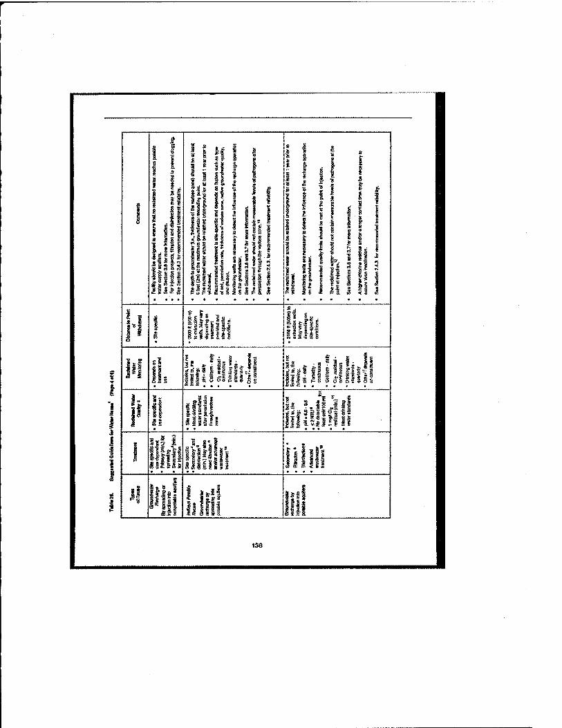
Itlll
1 1
tJ^ ■ ill
i So Jlllll
^«|? III 111 jljise-iill lg m
!
I 1
iiiifj ill ?.iiii| IHllltlif
iiiiiiif III
I ISifaf
Ifll
136
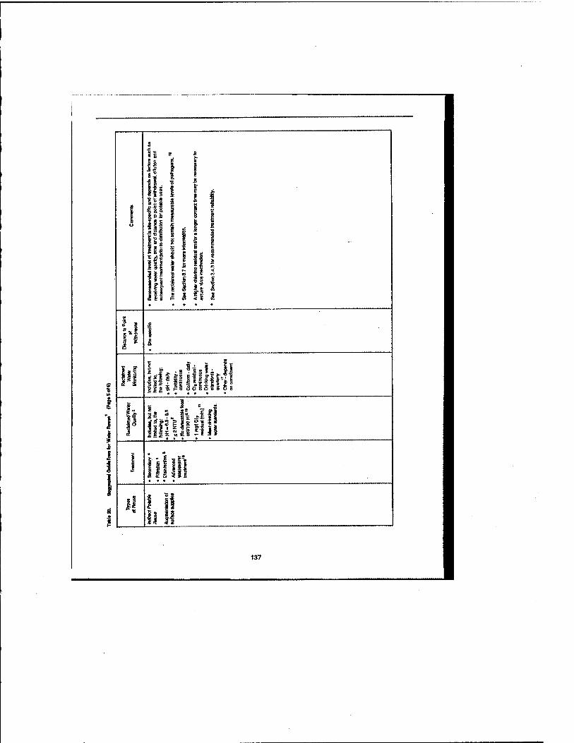
el
tl
in
i! I
111
II iff It
fi
i !ii 8|i t ti i III 3 SSi S 6!
ll Ills.
2
li%k% If li
lip Is Hi
137
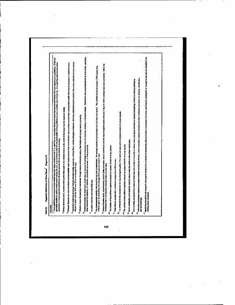
APPENDIX HI - IRRIGA TION SYSTEM
FOR THE FRONT NINE HOLES A T PINE
BAYOU GOLF COURSE, NCBC
GULFPORT, MS

n
5E3
UJ Lir ^
O t<>,
i
ti "Si
\
nil-
Hipti^^
S vf
TifflSi
^
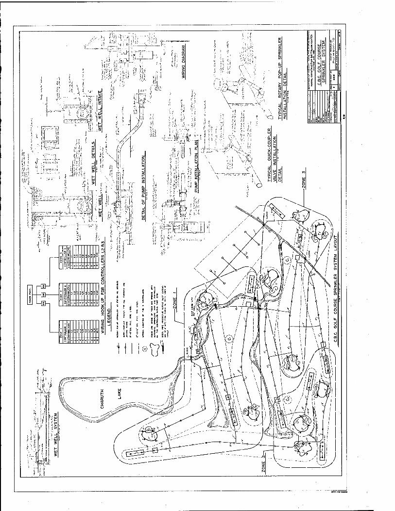
APPENDIX IV - IRRIGA TION SYSTEM
FOR THE BA CK NINE HOLES A T PINE
BA YOU GOLF COURSE, NCBC
GULFPORT, MS
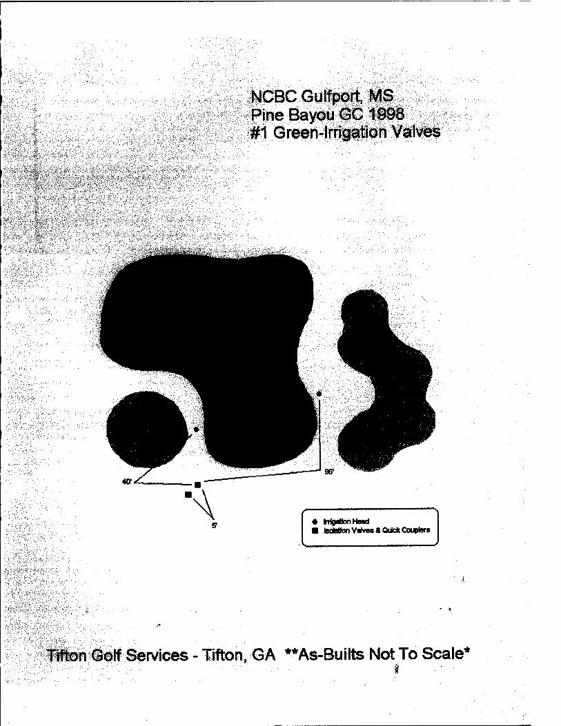
NCBC Gulfport, MS Pine Bayou GC 1998 #1 Green-Irrigation Valves
• *»«* ■ ■—■ iTigaDOn riBsa ■ IsoMion Valves 8 Quick Couplers
iiten Golf Sen/ices - lifton, GA **As-BuUts Not To Scale^
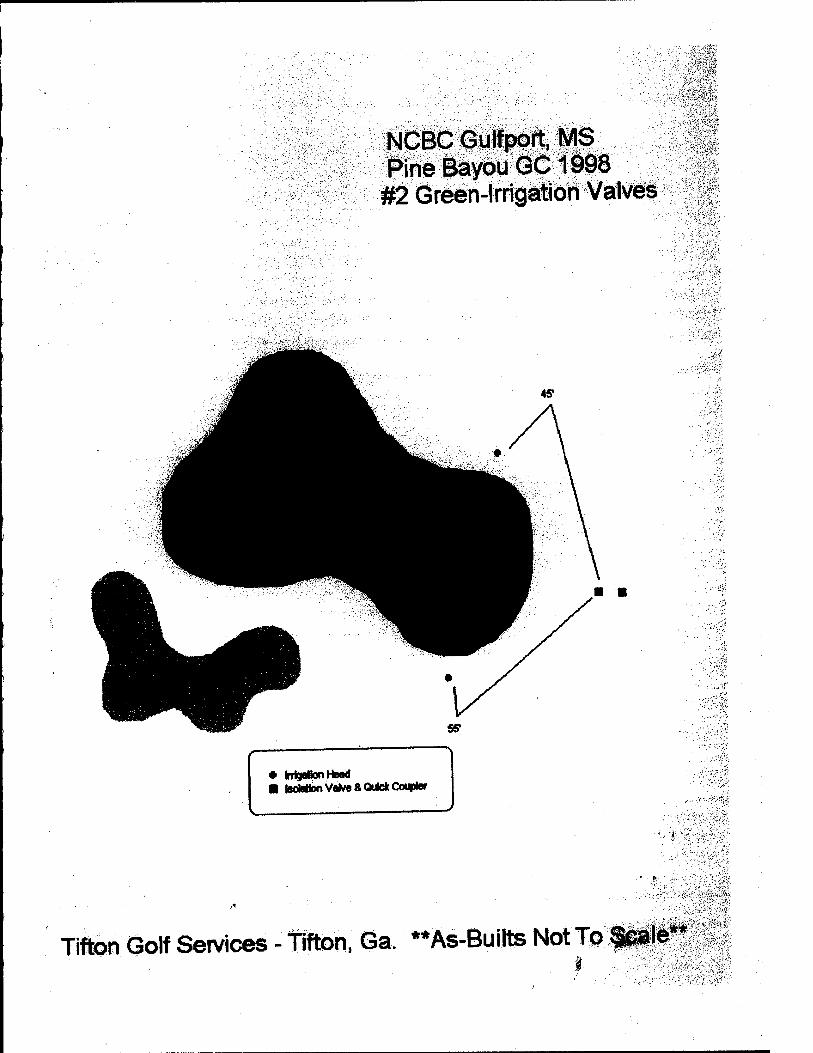
NCBC Gulfport, MS Pine Bayou GC1998 #2 Green-Irrigation Valves
mngMonriBaa ■ Isolation Valves Quick Coupler
Tifton Golf Services - Wton. Ga. **As-Builts Not To ««
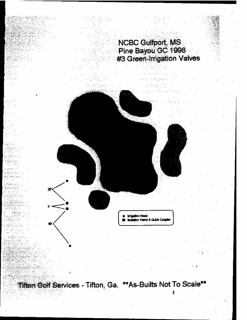
NCBC Gulfport, MS Pine Bayou GC 1998 #3 Green-Irrigation Valves
Tlflion Golf Services - Tifton, Ga. **As-'Builts Not To Scale**
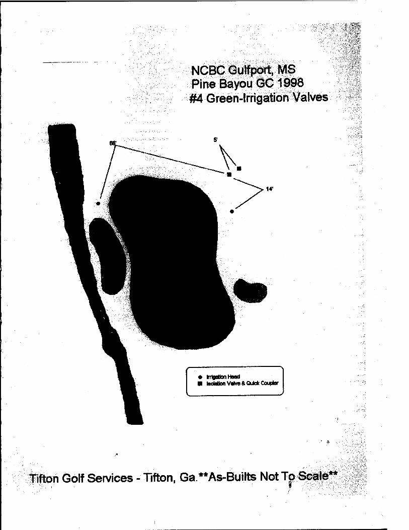
V'''
NCBC Gulfport, MS Pine Bayou GC 1998 #4 Green-Irrigation Valves
rngaoort rMH ■ ls(MtonValye&Qukd( Coupler
Tifton Golf Services - Tifton, Ga.**As-Builte NotTp Scale**
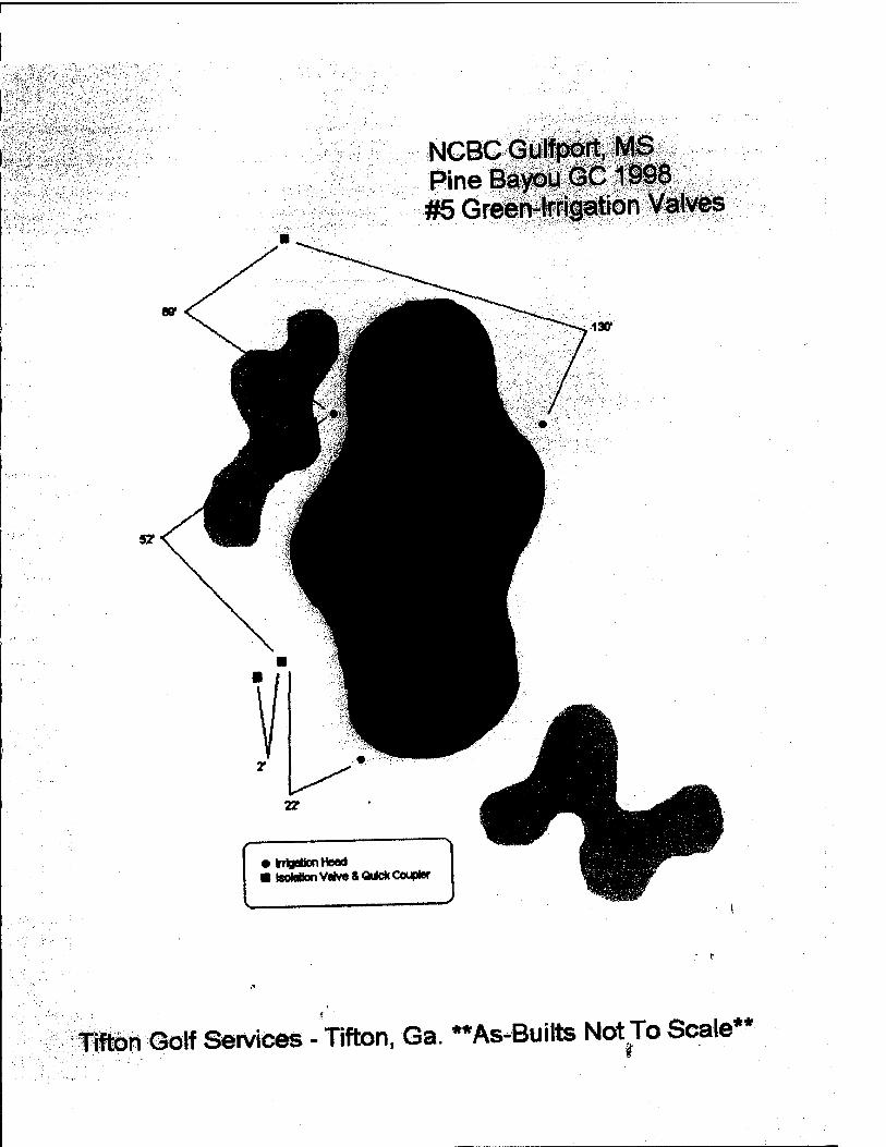
NGBC Gulfport, MS Pine Bayou GC1998 #5 Green-Irrigation Valves
irgBDonnecKi I isotaUon Valve &QiM(CouplM'
Titen Golf Services - Tifton. Ga. ••As^Builts Not To Scale**
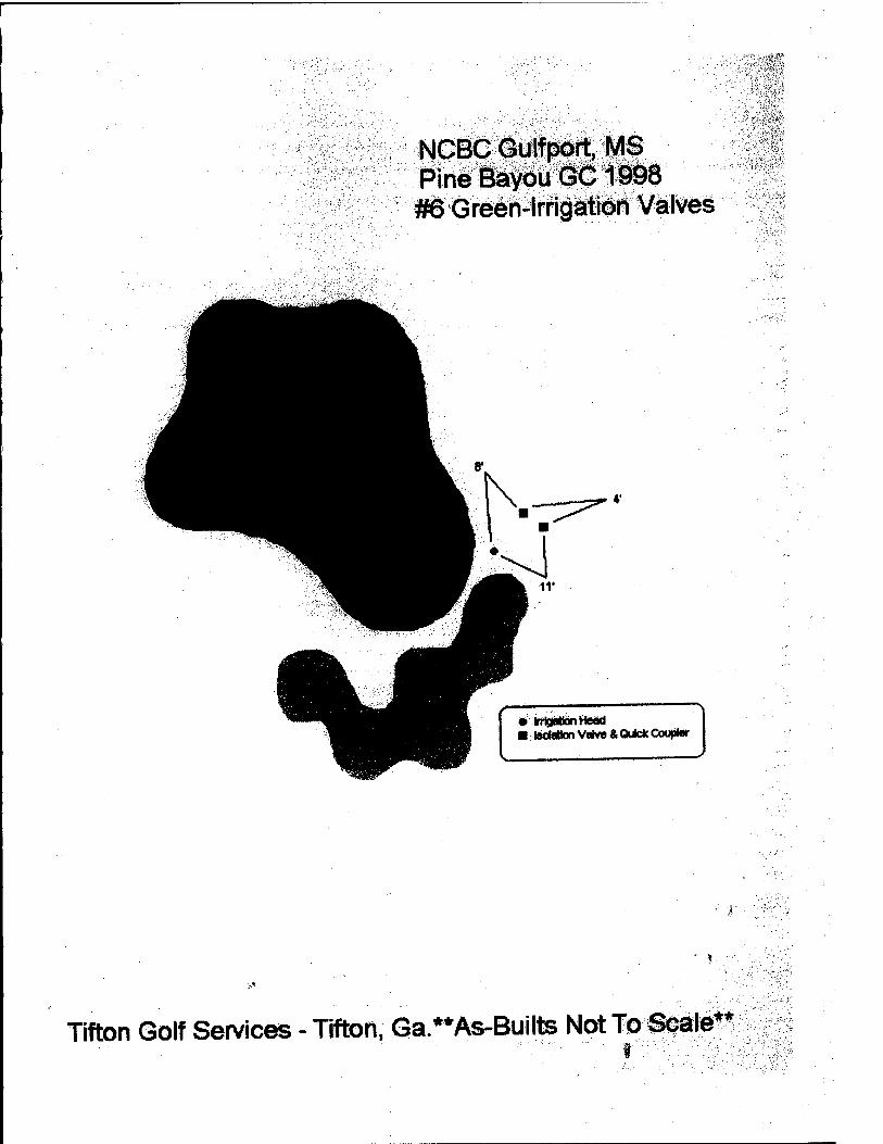
NCBC Gulf port, MS Pine Bayou GC 1998 #6 Green-Irrigation Valves
irljyMxinneao ■ IscMion Valve & Quicfc Coupler
Tifton Golf Services - Tifton, Ga.**As-Builts Not To Scale**
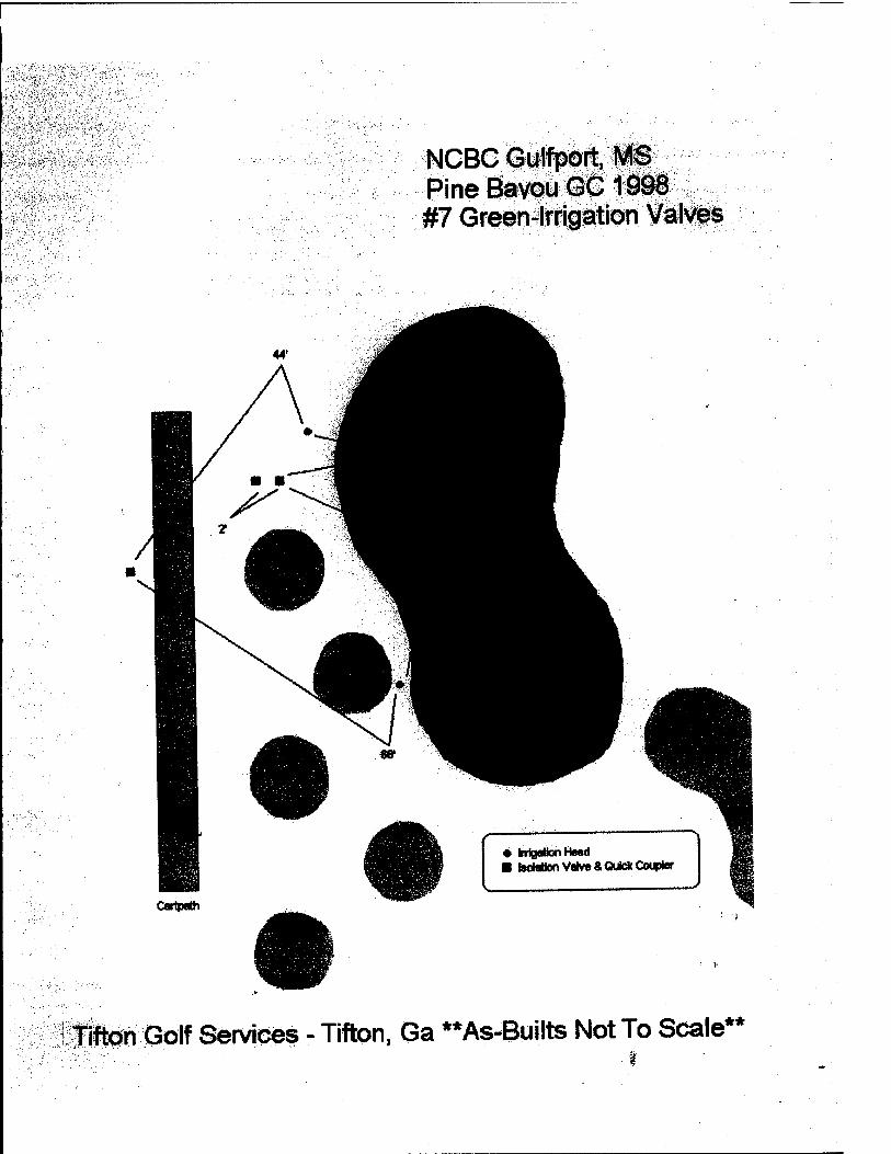
NCBC Gulfport, MS Pine BavouGC 1998 #7 Green-Irrigation Valves
• Irrigation He«d ■ teoMlon Valve & Quick Coupler
TIfton Golf Services - Tifton, Ga **As-Builts Not To Scale**

NCBC Gulfport, MS Pine Bayou GC1998 #8 Green-Irrigation Valves
43' 1'
tifton Golf SeMces -Tifton, Ga **As-Builts NotTo Scale**
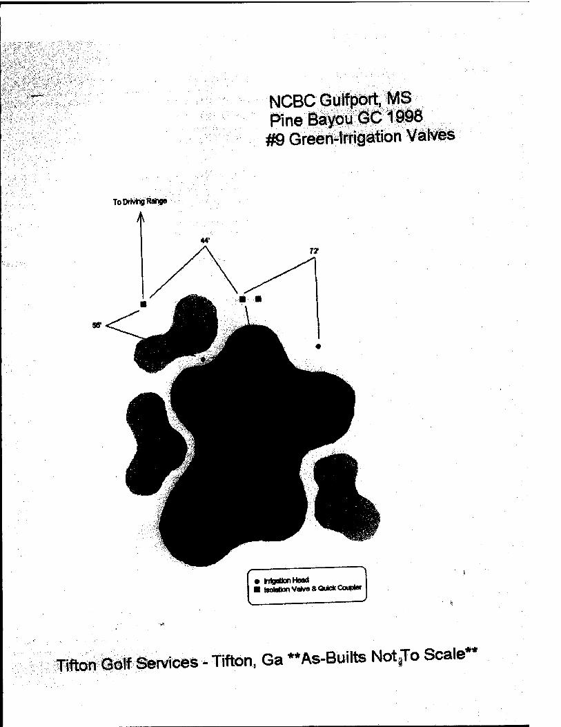
NCBC Gulfport, MS Wne Bayou GC1998 #9 Green-Irrigation Valves
• inlgattonHeeKl ■ tooWlon Valve a Quick Coupter
Tifton Golf Services - Tifton, Ga ••As-Builts Not^o Scale**
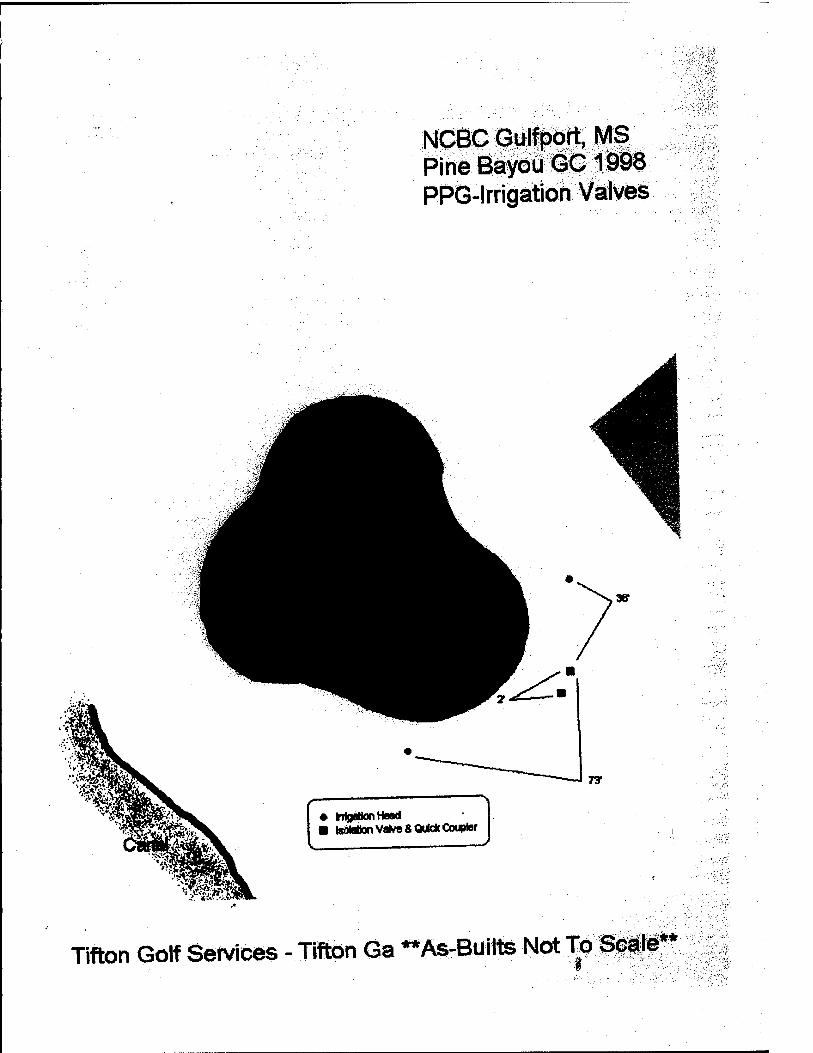
NCBC Gulfport, MS Pine Bayou GC 1998 PPG-lrrigation Valves
,\!.liv
• HgtfonHnd ■ isdMion Valve & Quick Coupler
Tifton Golf Services - Tifton Ga "As-Boilte Not To Scale**
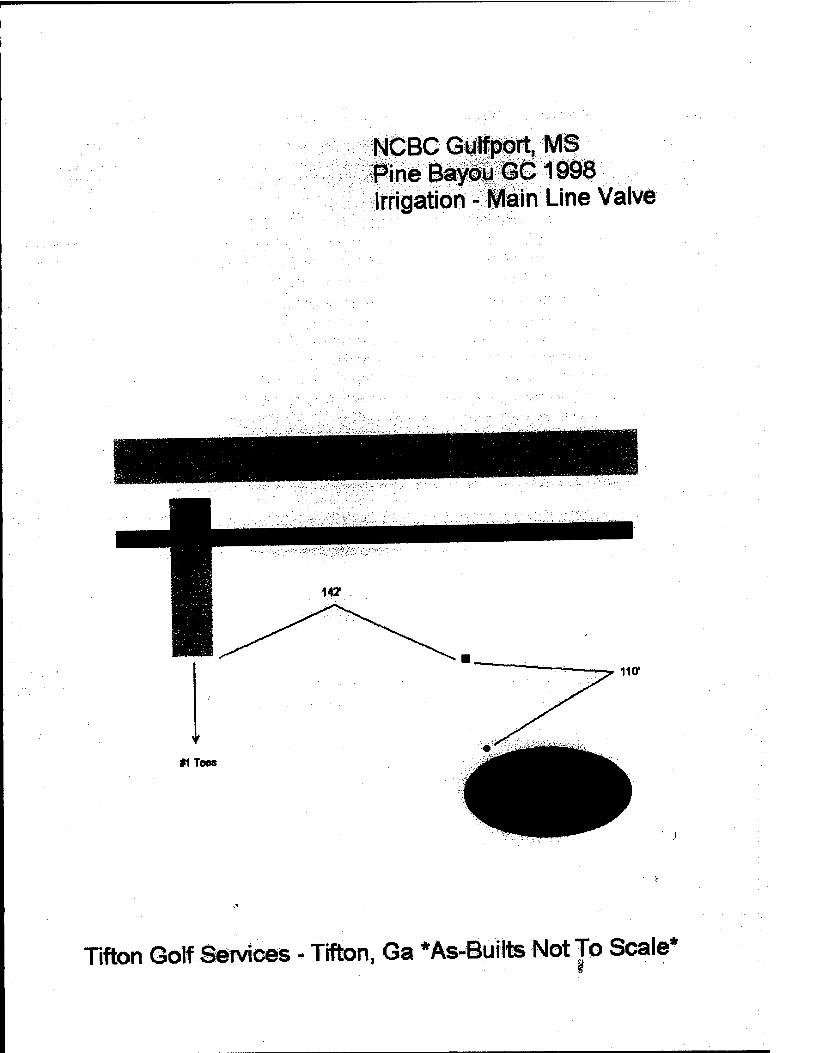
NCBC Gulfport, MS Pine Bayou GC1998 Irrigation - Main Line Valve
Tifton Golf Services - Tifton. Ga *As^©ullts NotTo Scale"
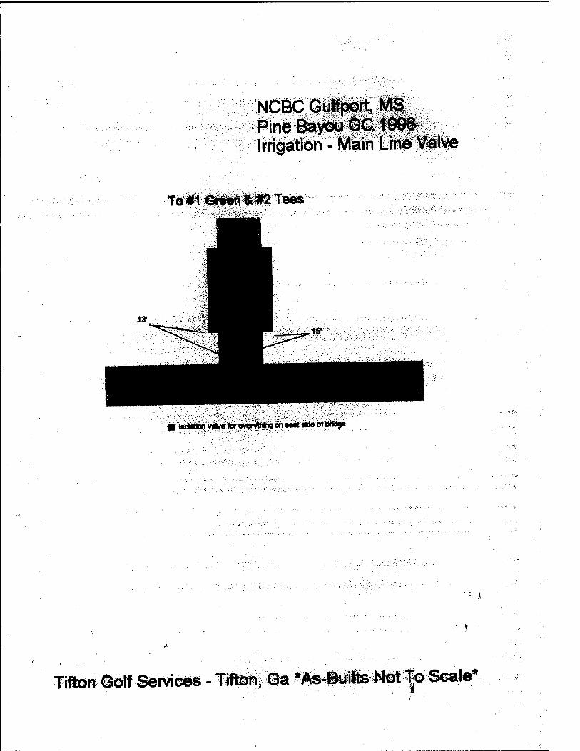
NCBC Gulfport, MS Pine Baydu @C. IddS Irrigation - Main Line Valve
To#1GfWftTees
m l8oMianvi*MtarevwylNng«iea««lteoft)rid9e
fill©rl#©[f Services - Tiften, Ga *As-©uHts Not To Sca<e^
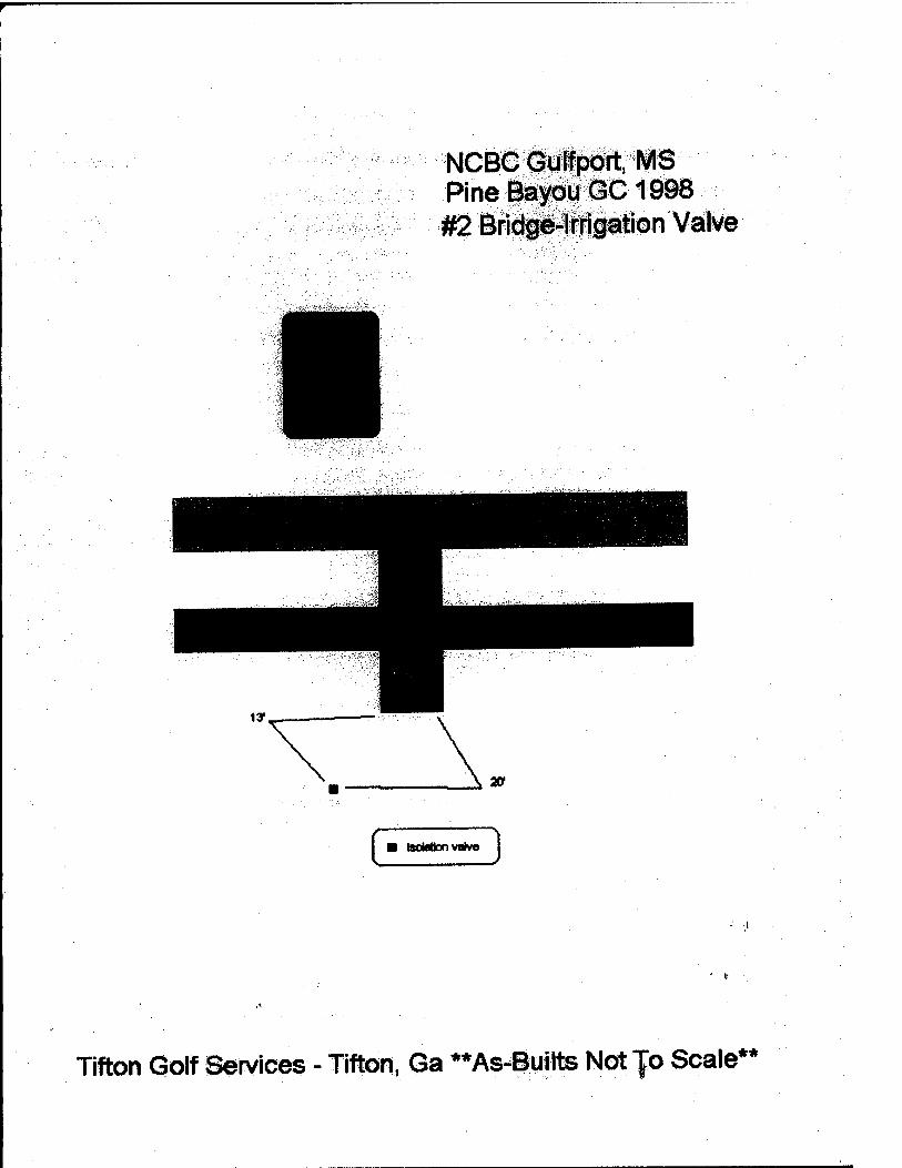
NCBC Gulfport, MS Pine Bayou GC 1998 #2 Bridge^lrrigation Val\/e
IsoMion valve
Tifton Golf Services - Tifton, Ga **As-Builts Not |o Scale**
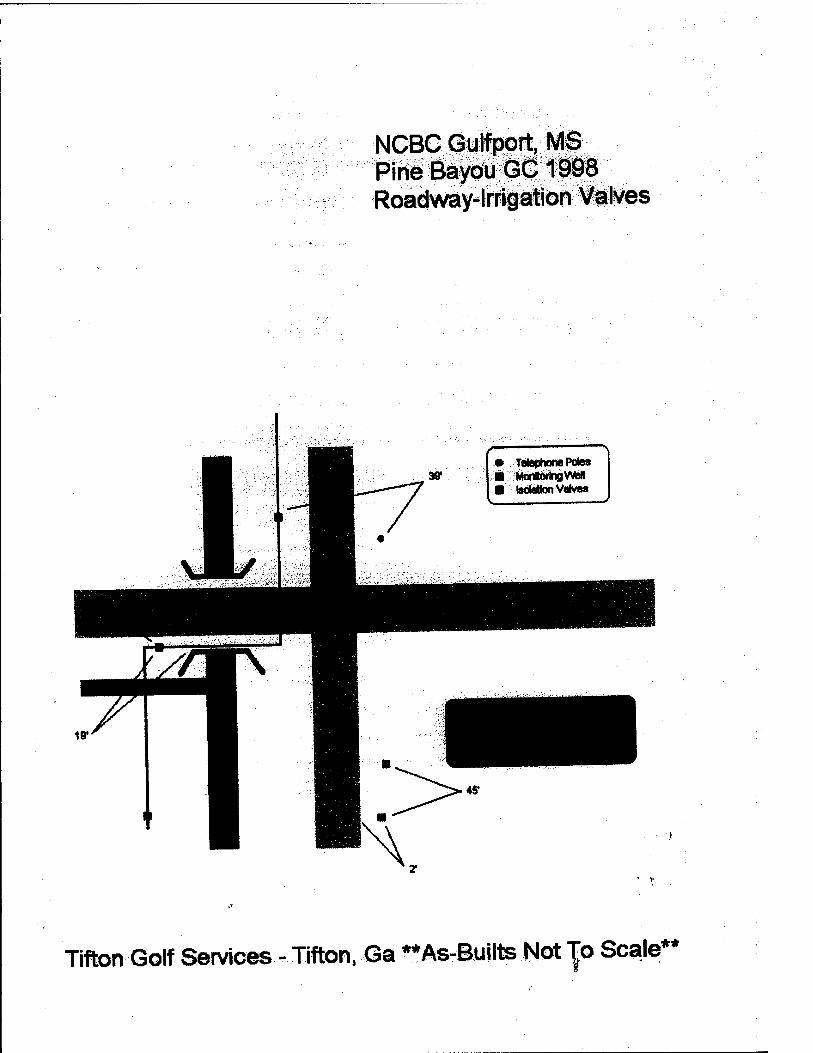
NCBC Gulfport, MS Pine Bayou GC 1998 Roadway-Irrigation Valves
• Telef)tane Poles
■ lutaUonVMves
Tifton Golf Services - Tifton, Ga **As-Builte Not To Scale**
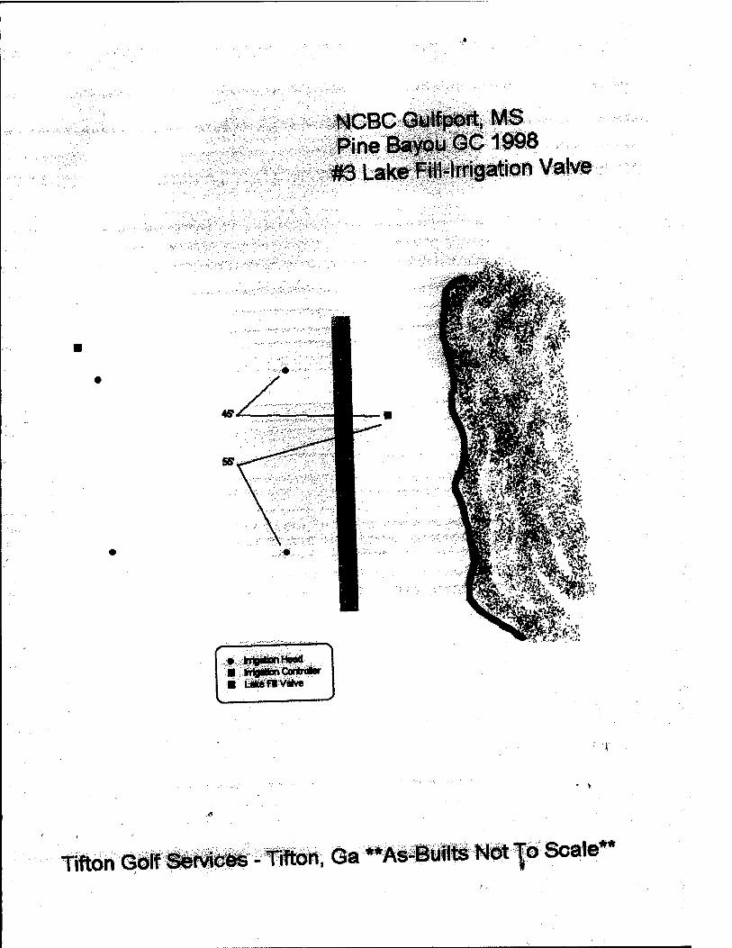
NCBC GyipDrt, MS Pine Bayou GC 1998
#3 LakeFHI-lrrigation \fi^m
• InigrilahHowl ■ kritfilionCanralar
Tifton Golf Servicfes - Tifton, Ga «As-Buflts Not-j;o Sca»e**
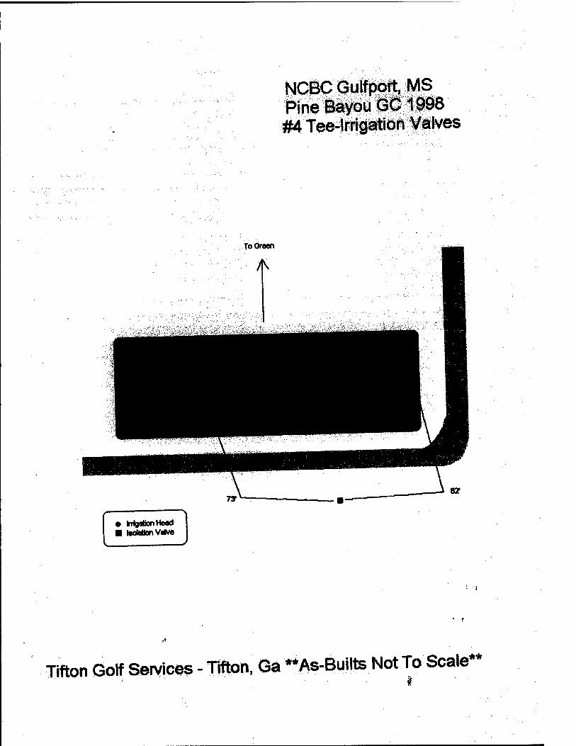
• IrrlgabonHead ■ IscMionVahw
NCBC Gulfport, MS Pine Bayou GC 1998 #4 Tee-Irrigation Valves
ToOreen
Tifton Golf Services - Tifton, Qa "As-BuHte Not To Scale**
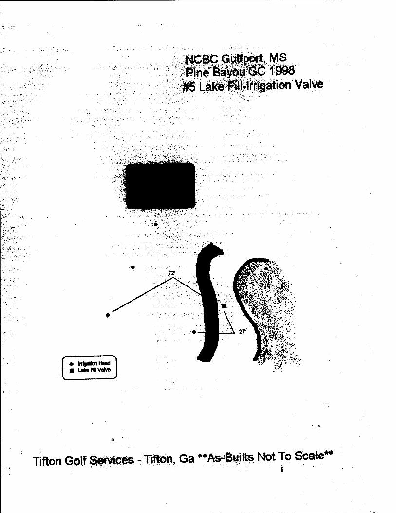
isieic <siiipit, MS iilf^^^:i998 ^^iJilii^iiation Valve
# rngMonnoaa ■ LfltoFlvaKw
i:^y^y-
Tifton Golf Services -imm, Ga **As-Builts Not To ScaJe**
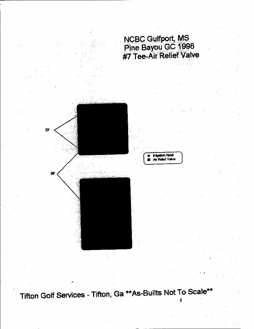
NCBC Gulfport, MS Pine Bayou GC1998 #7 Tee-Air Relief Valve
• IrrigaUDn I lead ■ AirRelef Valve J
Tifton Golf Services - Tifton, Ga •*As-Bullts Not To Scale**
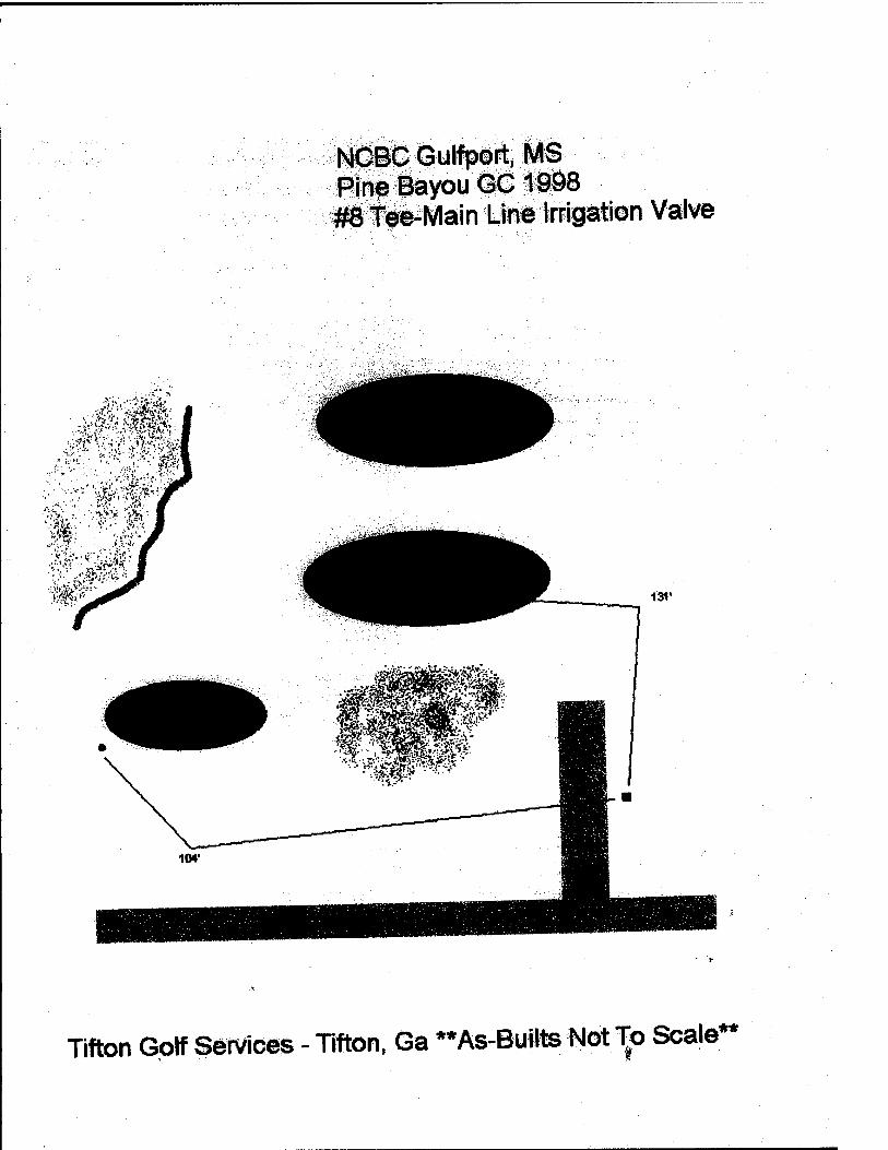
NCBC Gulfport, MS Pine Bayou GC 1998 #8 Tee-Main Line irrigation Valve
■ • ■■■■ -«'i?i;i'%^'-
Titton Golf services - Tifton, Ga ••As-Builts Not To Scale**
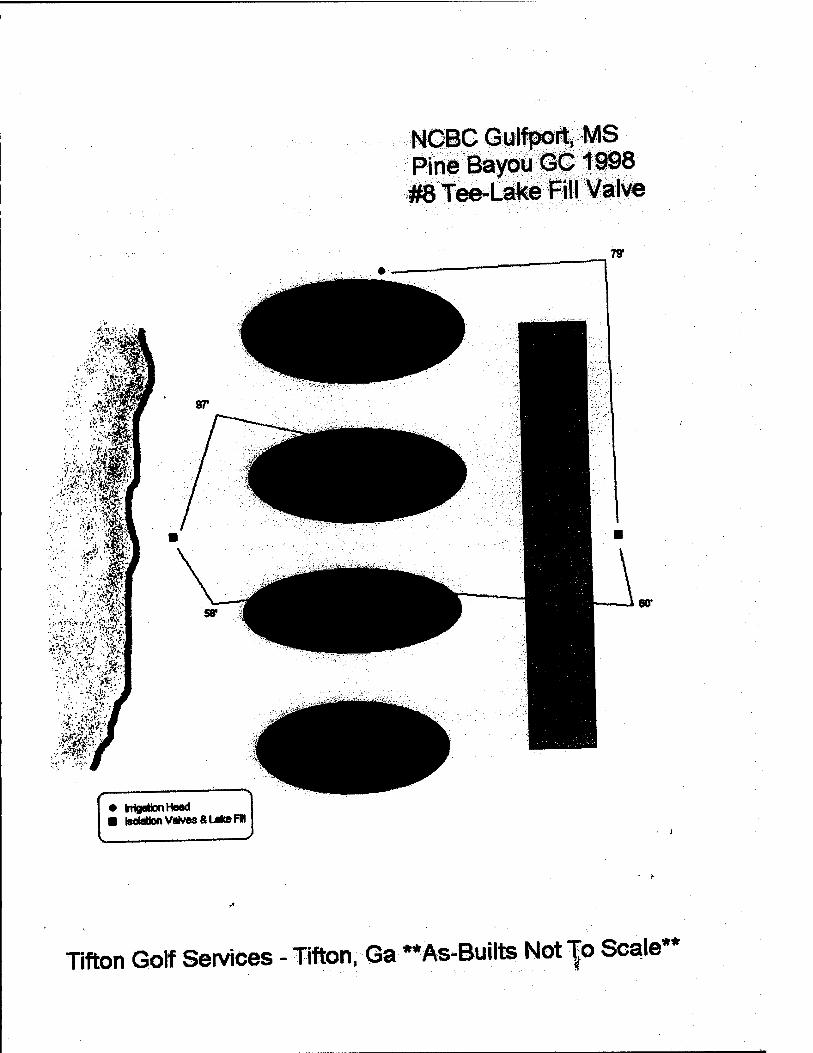
NCBC Gulfport, MS Pine Bayou GC 1998 #8 Tee-Lake Fill Valve
• imgetionHeacI ■ boMion Valves SUksFM
Titton Golf Services - Tifton. Ga "As-BuilteNot -^o Scale**
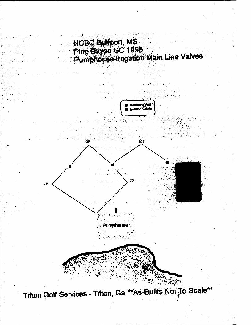
NCBG Gulf port, MS Pine lty©u GC1996 PumpW©yse-lFrigation Main Line Values
■ WwiortnaViWI ■ tooMionVrivm D
101'
w
Pumphouse
^ ijw.*: SAA fm
m^^^m j;^-< ;>:.io^5, >'; '^t
■" ■ '•■■>' •■:.-: A-.■! rC^T-wr-j- : •■^^.,^»■■■c^^lfe■ij■
Tifton Golf Sfeiviees - fiftOn, Ga **As-ttMttts Wot To Scale-
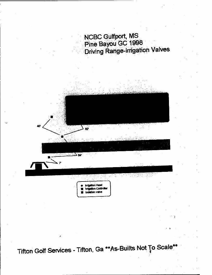
NCBC Gulfport, MS Pine Bayou GC1998 Driving Range-Irrigation Valves
• IrrtpknHaacI ■ IrrlgilionConbvlw ■ isdWionvaKn
Tifton Golf Services - Tifton, Ga ••fts-Builts Mot -fo Scale**
APPENDIX V-REFERENCES
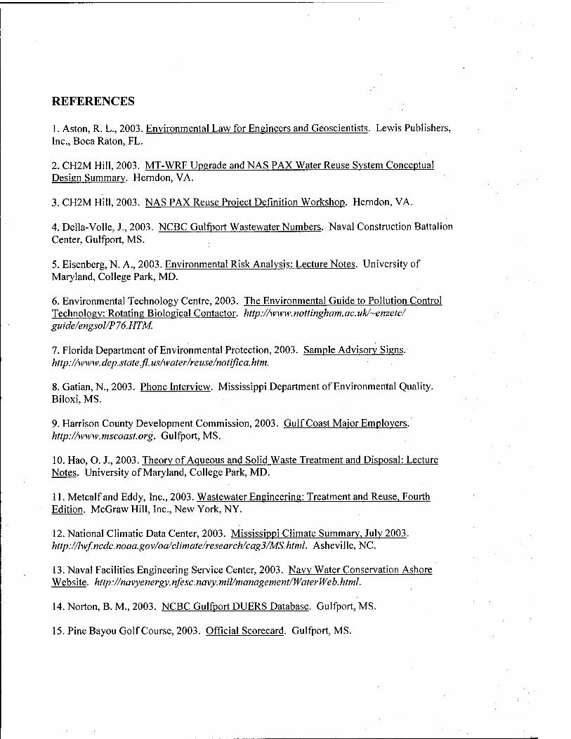
REFERENCES
1. Aston, R. L., 2003. Environmental Law for Engineers and Geoscientists. Lewis Publishers, Inc., Boca Raton, FL.
2. CH2M Hill, 2003. MT-WRF Upgrade and NAS PAX Water Reuse System Conceptual Design Summary. Herndon, VA.
3. CH2M Hill, 2003. NAS PAX Reuse Project Definition Workshop. Herndon, VA.
4. Delia-Voile, J., 2003. NCBC Gulfport Wastewater Numbers. Naval Construction Battalion Center, Gulfport, MS.
5. Eisenberg, N. A., 2003. Environmental Risk Analysis: Lecture Notes. University of Maryland, College Park, MD.
6. Environmental Technology Centre, 2003. The Environmental Guide to Pollution Control Technology: Rotating Biological Contactor, http://www.nottingham.ac.uk/~enzetc/ guide/engsol/P76.HTM.
7. Florida Department of Environmental Protection, 2003. Sample Advisory Signs. http://www.dep.state.fl.us/water/reuse/notifica.htm.
8. Gatian, N., 2003. Phone Interview. Mississippi Department of Environmental Quality. Biloxi, MS.
9. Harrison County Development Commission, 2003. Gulf Coast Major Employers. http://www.mscoast.org. Gulfport, MS.
10. Hao, O. J., 2003. Theory of Aqueous and Solid Waste Treatment and Disposal: Lecture Notes. University of Maryland, College Park, MD.
11. Metcalf and Eddy, Inc., 2003. Wastewater Engineering: Treatment and Reuse. Fourth Edition. McGraw Hill, Inc., New York, NY.
12. National Climatic Data Center, 2003. Mississippi Climate Summary, July 2003. http://lwf.ncdc.noaa.gov/oa/climate/research/cag3/MS.html. Asheville, NC.
13. Naval Facilities Engineering Service Center, 2003. Navy Water Conservation Ashore Website. http://navyenergy.nfesc.navy.mil/management/WaterWeb.html.
14. Norton, B.M., 2003. NCBC Gulfport DUERS Database. Gulfport, MS.
15. Pine Bayou Golf Course, 2003. Official Scorecard. Gulfport, MS.
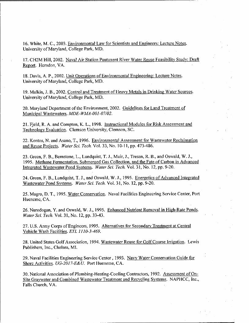
16. White, M. C, 2003. Environmental Law for Scientists and Engineers: Lecture Notes. University of Maryland, College Park, MD.
17. CH2M Hill, 2002. Naval Air Station Pautuxent River Water Reuse Feasibility Studv: Draft Report. Herndon, VA.
18. Davis, A. P., 2002. Unit Operations of Environmental Engineering: Lecture Notes. University of Maryland, College Park, MD.
19. Malkin, J. B., 2002. Control and Treatment of Heaw Metals in Drinking Water Sources. University of Maryland, College Park, MD.
20. Maryland Department of the Environment, 2002. Guidelines for Land Treatment of Municipal Wastewaters. MDE-WMA-001-07/02.
21. Fjeld, R. A. and Compton, K. L., 1998. Instructional Modules for Risk Assessment and Technology Evaluation. Clemson University, Clemson, SC.
22. Kontos, N. and Asano, T., 1996. Environmental Assessment for Wastewater Reclaimation and Reuse Projects. Water Sci. Tech. Vol. 33, No. 10-11, pp. 473-486.
23. Green, F. B., Bemstone, L., Lundquist, T. J., Muir, J., Tresan, R. B., and Oswald, W. J., 1995. Methane Fermentation, Submerged Gas Collection, and the Fate of Carbon in Advanced Integrated Wastewater Pond Systems. Water Sci. Tech. Vol. 31, No. 12, pp. 9-20.
24. Green, F. B., Lundquist, T. J., and Oswald, W. J., 1995. Energetics of Advanced Integrated Wastewater Pond Systems. Water Sci. Tech. Vol. 31, No. 12, pp. 9-20.
25. Magro, D. T., 1995. Water Conservation. Naval Facilities Engineering Service Center, Port Hueneme, CA.
26. Nurodogan, Y. and Oswald, W. J., 1995. Enhanced Nutrient Removal in High-Rate Ponds. Water Sci. Tech. Vol. 31, No. 12, pp. 33-43.
27. U.S. Army Corps of Engineers, 1995. Alternatives for Secondary Treatment at Central Vehicle Wash Facilities. ETLlll0-3-469.
28. United States Golf Association, 1994. Wastewater Reuse for Golf Course Irrigation. Lewis Publishers, Inc., Chelsea, MI.
29. Naval Facilities Engineering Service Center, 1993. Navy Water Conservation Guide for Shore Activities. UG-2017-E&U. Port Hueneme, CA.
30. National Association of Plumbing-Heating-Cooling Contractors, 1992. Assessment of On- Site Graywater and Combined Wastewater Treatment and Recycling Systems. NAPHCC, Inc., Falls Church, VA.
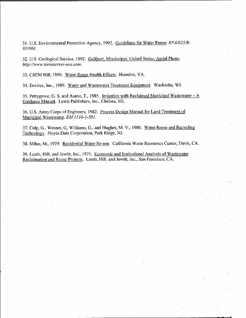
31. U.S. Environmental Protection Agency, 1992. Guidelines for Water Reuse. EPA/625/R- 92/004.
32. U.S. Geological Service, 1992. Gulfport, Mississippi. United States: Aerial Photo. http://ww\v.terraserver-usa.com.
33. CH2M Hill, 1990. Water Reuse Health Effects. Herndon, VA.
34. Envirex, Inc., 1989. Water and Wastewater Treatment Equipment. Waukesha, WI.
35. Pettygrove, G. S. and Asano, T., 1985. Irrigation with Reclaimed Municipal Wastewater-A Guidance Manual. Lewis Publishers, Inc., Chelsea, MI.
36. U.S. Army Corps of Engineers, 1982. Process Design Manual for Land Treatment of Municipal Wastewater. EM 1110-1-501.
37. Culp, G., Wesner, G, Williams, G., and Hughes, M. V., 1980. Water Reuse and Recycling Technology. Noyes Data Corporation, Park Ridge, NJ.
38. Milne, M., 1979. Residential Water Re-use. California Water Resources Center, Davis, CA.
39. Leeds, Hill, and Jewitt, Inc., 1971. Economic and Institutional Analysis of Wastewater Reclaimation and Reuse Projects. Leeds, Hill, and Jewitt, Inc., San Fransisco, CA.