Embed Size (px)
Citation preview
Planning and Implementing an F5® BIG-IQ®
Centralized Management Deployment
Version 5.4

Table of Contents
Planning and Implementing a Centralized Management Deployment................................... 5Which type of centralized management solution do you want to deploy?..........................5What elements make up a centralized management solution?..........................................6Network requirements for a BIG-IQ Centralized Management deployment....................... 7
Before you deploy a centralized management solution...........................................7BIG-IQ Centralized Management Deployment.................................................................14
How do I deploy a BIG-IQ system?....................................................................... 14How do I license and do the basic setup to start using BIG-IQ?...........................15
BIG-IQ Data Collection Device Deployment.....................................................................19How do I deploy a data collection device cluster?.................................................19Data collection device sizing guidelines................................................................ 36
Managing a Data Collection Device Cluster........................................................................... 37Data collection device best practices............................................................................... 37Restore data collection device snapshots........................................................................37Delete a data collection device snapshot.........................................................................38Check data collection device health.................................................................................38Index rotation policy......................................................................................................... 39Changing the minimum number of master eligible devices..............................................40
Managing Disaster Recovery Scenarios.................................................................................41How does a data collection device cluster deal with disaster recovery scenarios?......... 41
How does the minimum master eligible devices setting work?............................. 43How is alert data handled when data collection devices fail?............................... 43How is data handled when communication between the two data centers
fails?................................................................................................................. 44How do I optimize my deployment for disaster recovery?..................................... 45Changing the minimum number of master eligible devices................................... 45How do I perform routine maintenance on a node?.............................................. 45How do I change the zone for a data collection device?....................................... 46
Legal Notices............................................................................................................................ 47Legal notices....................................................................................................................47
Table of Contents
3

Table of Contents
4
Planning and Implementing a Centralized ManagementDeployment
Which type of centralized management solution do you want to deploy?There are two license types for a centralized management solution, one for BIG-IQ device managementand one for a data collection device (DCD).
BIG-IQ device management
F5® BIG-IQ® Centralized Management is a platform that you use as a tool to help you manage BIG-IP®
devices and all of their services (such as LTM®, AFM®, ASM®, and so forth), from one location. BIG-IQcan manage up to 200 (physical, virtual, or vCMP®) BIG-IP devices and handle licensing for up to 5,000unmanaged devices.
Using BIG-IQ helps you more efficiently manage your BIG-IP devices. That means you and your co-workers don't have to log in to individual BIG-IP systems to get your job done. Instead, you can discover,upgrade, deploy policy changes, manage licenses, and more, from just one place.
From BIG-IQ, you can manage a variety of tasks from software updates to health monitoring, and trafficto security. And because permissions for users are role-based, you can limit access to just a few trustedadministrators to minimize downtime and potential security issues. You can also allow users to view oredit only those BIG-IP objects that they need to do their job.
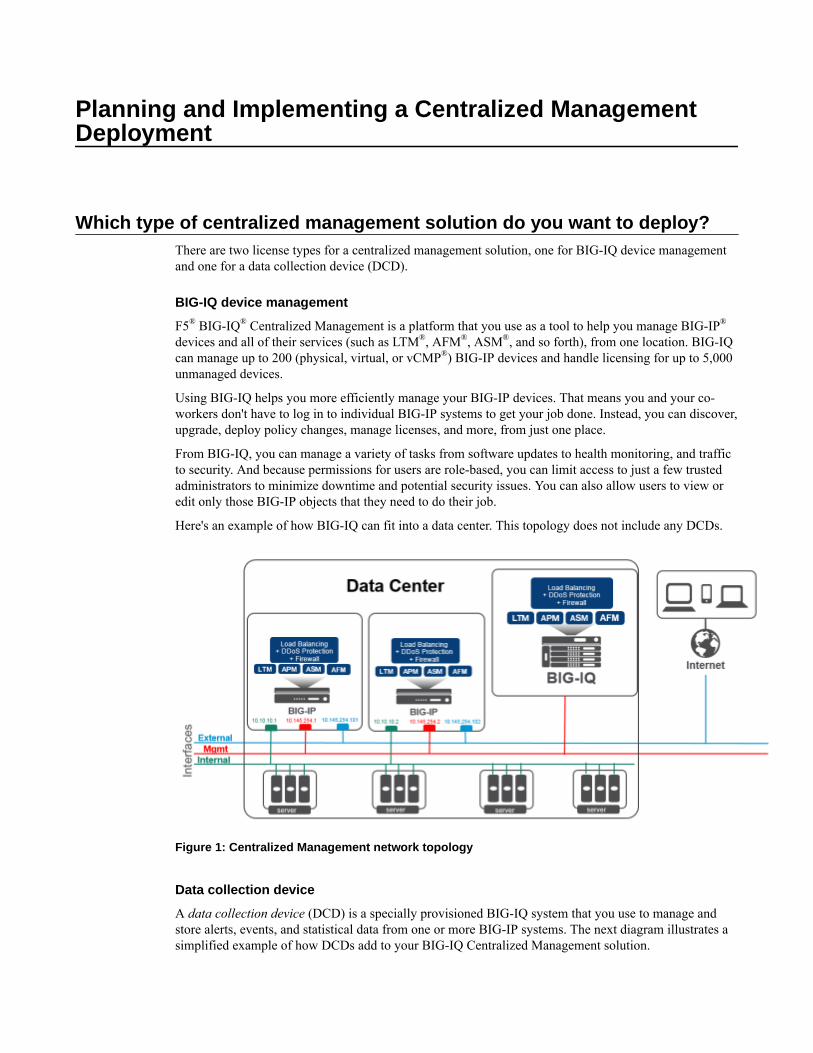
Here's an example of how BIG-IQ can fit into a data center. This topology does not include any DCDs.
Figure 1: Centralized Management network topology
Data collection device
A data collection device (DCD) is a specially provisioned BIG-IQ system that you use to manage andstore alerts, events, and statistical data from one or more BIG-IP systems. The next diagram illustrates asimplified example of how DCDs add to your BIG-IQ Centralized Management solution.
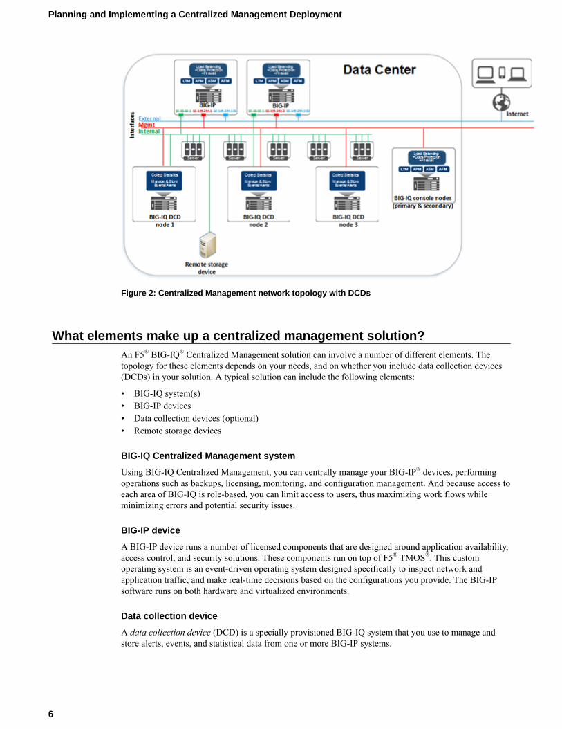
Figure 2: Centralized Management network topology with DCDs
What elements make up a centralized management solution?An F5® BIG-IQ® Centralized Management solution can involve a number of different elements. Thetopology for these elements depends on your needs, and on whether you include data collection devices(DCDs) in your solution. A typical solution can include the following elements:
• BIG-IQ system(s)• BIG-IP devices• Data collection devices (optional)• Remote storage devices
BIG-IQ Centralized Management system
Using BIG-IQ Centralized Management, you can centrally manage your BIG-IP® devices, performingoperations such as backups, licensing, monitoring, and configuration management. And because access toeach area of BIG-IQ is role-based, you can limit access to users, thus maximizing work flows whileminimizing errors and potential security issues.
BIG-IP device
A BIG-IP device runs a number of licensed components that are designed around application availability,access control, and security solutions. These components run on top of F5® TMOS®. This customoperating system is an event-driven operating system designed specifically to inspect network andapplication traffic, and make real-time decisions based on the configurations you provide. The BIG-IPsoftware runs on both hardware and virtualized environments.
Data collection device
A data collection device (DCD) is a specially provisioned BIG-IQ system that you use to manage andstore alerts, events, and statistical data from one or more BIG-IP systems.
Planning and Implementing a Centralized Management Deployment
6
Configuration tasks on the BIG-IP system determine when and how alerts or events are triggered on theclient. The alerts or events are sent to a data collection device in a BIG-IQ Centralized Managementdeployment, and the BIG-IQ system retrieves them for your analysis. When you opt to collect statisticaldata from the BIG-IP devices, the DCD periodically retrieves those statistics from your devices, and thenprocesses and stores that data.
The group of data collection devices and BIG-IQ systems that work together to store and manage yourdata are referred to as the data collection cluster. The individual data collection devices are generallyreferred to as nodes.
Remote storage device
You need a remote storage device only when your deployment includes a data collection device (DCD)and you plan to store backups of your events, alerts, and statistical data for disaster recoveryrequirements. You also need remote storage so that you can retain this data when you upgrade yoursoftware.
Network requirements for a BIG-IQ Centralized Management deployment
Before you deploy a centralized management solution
Before you begin to deploy a BIG-IQ® system, you should complete these preparations.
• Determine the deployment scenario that works best for your needs.• Create the interfaces, communications, and networks needed to support your deployment scenario.• Configure your network (including switches and firewalls) to permit BIG-IQ network traffic to flow
based on the deployment scenario you choose.• Assemble the passwords, IP addresses, and licensing information needed for the BIG-IQ cluster
components.
Planning for a centralized management deployment
To successfully deploy a BIG-IQ® Centralized Management solution, you might need to coordinate withseveral people in your company.
If you use BIG-IQ virtual editions, you might need to coordinate with the people who manage yourvirtual environment, so they can provision the virtual machines with the required amount of CPUs,memory, and network interfaces. Further, you’ll need to coordinate with the people who manage thestorage for the virtual machines to make sure each virtual machine is provisioned with the necessarystorage to support the BIG-IQ environment. You also might need to provide the virtual environment teama copy of the BIG-IQ virtual machine image (available from https://downloads.f5.com), depending onhow they operate.
If you use BIG-IQ 7000 devices in your network, you need to coordinate with the people who manage thedata center where the BIG-IQ devices are housed, to make arrangements for the devices to be racked,powered on, and connected to your network.
There are also several tasks to coordinate with your networking team:
• IP address allocation for the BIG-IQ nodes, depending on your deployment model.• Creation of networks, VLANs, and so on, that are dependent on your deployment model.• Any routing configuration required to ensure that traffic passes between the BIG-IQ nodes and the
BIG-IP® devices.• Additional networking configuration required to support the BIG-IQ system's operation.
Finally, you might need to coordinate with your network firewall administrators, depending on thenetwork configuration at your company. The BIG-IQ software needs to communicate between BIG-IQ
Planning and Implementing an F5 BIG-IQ Centralized Management Deployment
7
nodes and BIG-IP systems; and, if there are firewalls in the network path, firewall rules probably need tobe configured to permit that traffic. For additional detail about required network ports and protocols, referto Open ports required for BIG-IQ system deployment.
Determining the network configuration needed for your deployment
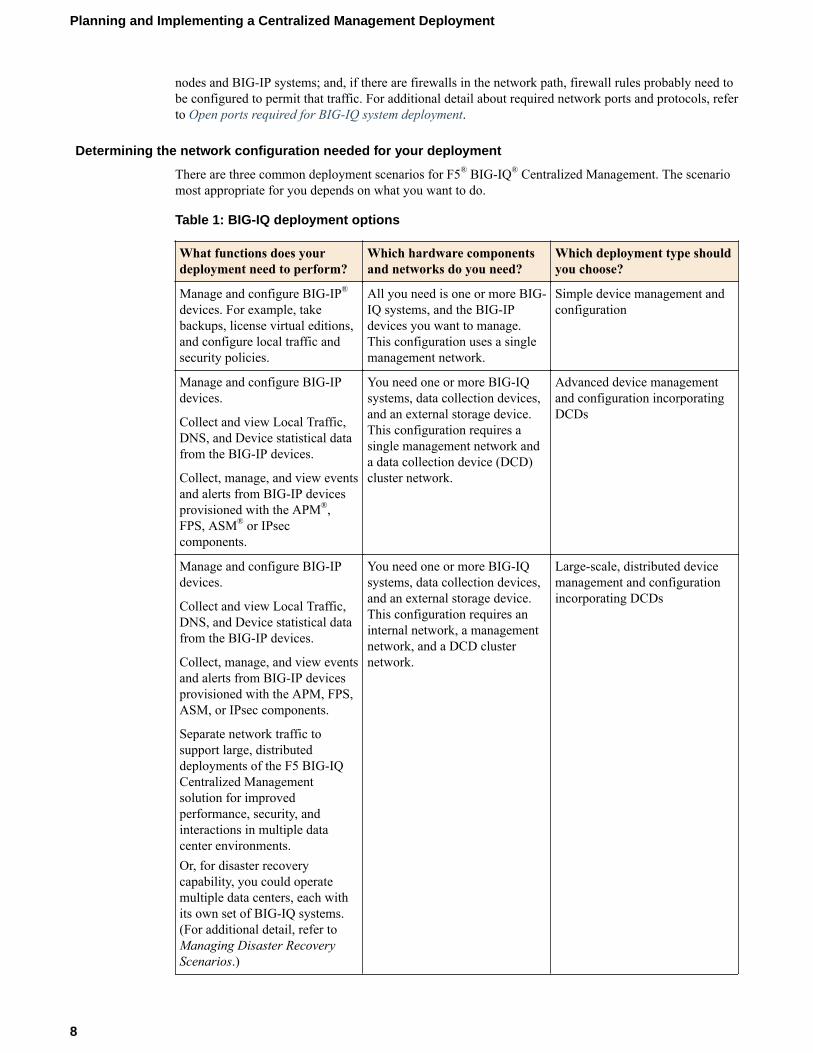
There are three common deployment scenarios for F5® BIG-IQ® Centralized Management. The scenariomost appropriate for you depends on what you want to do.
Table 1: BIG-IQ deployment options
What functions does yourdeployment need to perform?
Which hardware componentsand networks do you need?
Which deployment type shouldyou choose?
Manage and configure BIG-IP®
devices. For example, takebackups, license virtual editions,and configure local traffic andsecurity policies.
All you need is one or more BIG-IQ systems, and the BIG-IPdevices you want to manage.This configuration uses a singlemanagement network.
Simple device management andconfiguration
Manage and configure BIG-IPdevices.
Collect and view Local Traffic,DNS, and Device statistical datafrom the BIG-IP devices.
Collect, manage, and view eventsand alerts from BIG-IP devicesprovisioned with the APM®,FPS, ASM® or IPseccomponents.
You need one or more BIG-IQsystems, data collection devices,and an external storage device.This configuration requires asingle management network anda data collection device (DCD)cluster network.
Advanced device managementand configuration incorporatingDCDs
Manage and configure BIG-IPdevices.
Collect and view Local Traffic,DNS, and Device statistical datafrom the BIG-IP devices.
Collect, manage, and view eventsand alerts from BIG-IP devicesprovisioned with the APM, FPS,ASM, or IPsec components.
Separate network traffic tosupport large, distributeddeployments of the F5 BIG-IQCentralized Managementsolution for improvedperformance, security, andinteractions in multiple datacenter environments.Or, for disaster recoverycapability, you could operatemultiple data centers, each withits own set of BIG-IQ systems.(For additional detail, refer toManaging Disaster RecoveryScenarios.)
You need one or more BIG-IQsystems, data collection devices,and an external storage device.This configuration requires aninternal network, a managementnetwork, and a DCD clusternetwork.
Large-scale, distributed devicemanagement and configurationincorporating DCDs
Planning and Implementing a Centralized Management Deployment
8
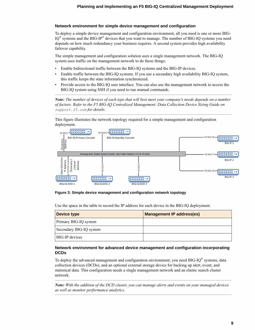
Network environment for simple device management and configuration
To deploy a simple device management and configuration environment, all you need is one or more BIG-IQ® systems and the BIG-IP® devices that you want to manage. The number of BIG-IQ systems you needdepends on how much redundancy your business requires. A second system provides high availabilityfailover capability.
The simple management and configuration solution uses a single management network. The BIG-IQsystem uses traffic on the management network to do these things:
• Enable bidirectional traffic between the BIG-IQ systems and the BIG-IP devices.• Enable traffic between the BIG-IQ systems. If you use a secondary high availability BIG-IQ system,
this traffic keeps the state information synchronized.• Provide access to the BIG-IQ user interface. You can also use the management network to access the
BIG-IQ system using SSH if you need to run manual commands.
Note: The number of devices of each type that will best meet your company's needs depends on a numberof factors. Refer to the F5 BIG-IQ Centralized Management: Data Collection Device Sizing Guide onsupport.f5.com for details.
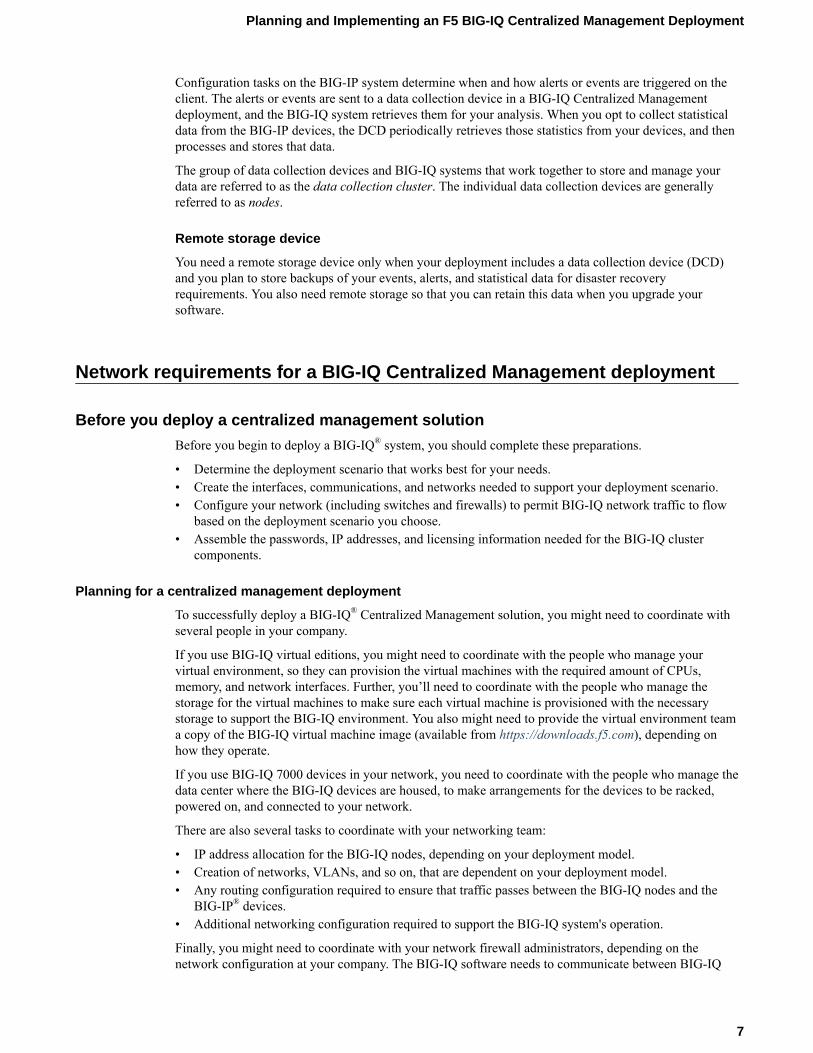
This figure illustrates the network topology required for a simple management and configurationdeployment.
Figure 3: Simple device management and configuration network topology
Use the space in the table to record the IP address for each device in the BIG-IQ deployment.
Device type Management IP address(es)
Primary BIG-IQ system
Secondary BIG-IQ system
BIG-IP devices
Network environment for advanced device management and configuration incorporatingDCDs
To deploy the advanced management and configuration environment, you need BIG-IQ® systems, datacollection devices (DCDs), and an optional external storage device for backing up alert, event, andstatistical data. This configuration needs a single management network and an elastic search clusternetwork.
Note: With the addition of the DCD cluster, you can manage alerts and events on your managed devicesas well as monitor performance analytics.
Planning and Implementing an F5 BIG-IQ Centralized Management Deployment
9
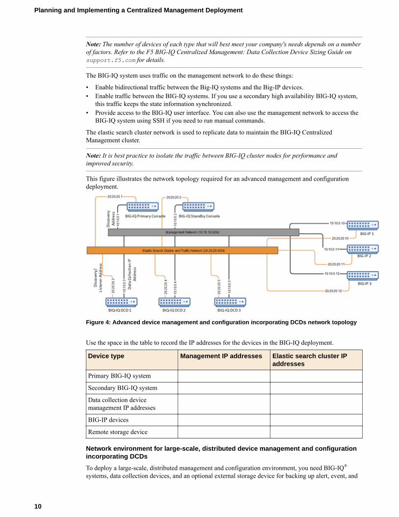
Note: The number of devices of each type that will best meet your company's needs depends on a numberof factors. Refer to the F5 BIG-IQ Centralized Management: Data Collection Device Sizing Guide onsupport.f5.com for details.
The BIG-IQ system uses traffic on the management network to do these things:
• Enable bidirectional traffic between the Big-IQ systems and the Big-IP devices.• Enable traffic between the BIG-IQ systems. If you use a secondary high availability BIG-IQ system,
this traffic keeps the state information synchronized.• Provide access to the BIG-IQ user interface. You can also use the management network to access the
BIG-IQ system using SSH if you need to run manual commands.
The elastic search cluster network is used to replicate data to maintain the BIG-IQ CentralizedManagement cluster.
Note: It is best practice to isolate the traffic between BIG-IQ cluster nodes for performance andimproved security.
This figure illustrates the network topology required for an advanced management and configurationdeployment.
Figure 4: Advanced device management and configuration incorporating DCDs network topology
Use the space in the table to record the IP addresses for the devices in the BIG-IQ deployment.
Device type Management IP addresses Elastic search cluster IPaddresses
Primary BIG-IQ system
Secondary BIG-IQ system
Data collection devicemanagement IP addresses
BIG-IP devices
Remote storage device
Network environment for large-scale, distributed device management and configurationincorporating DCDs
To deploy a large-scale, distributed management and configuration environment, you need BIG-IQ®
systems, data collection devices, and an optional external storage device for backing up alert, event, and
Planning and Implementing a Centralized Management Deployment
10
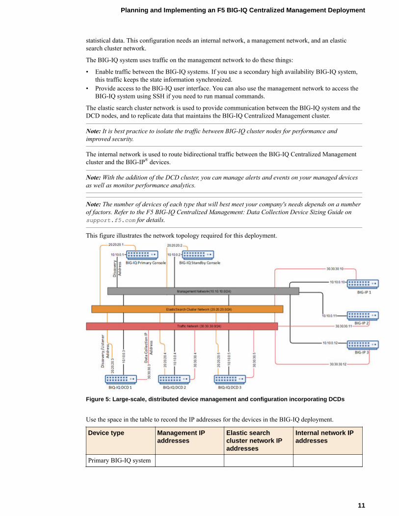
statistical data. This configuration needs an internal network, a management network, and an elasticsearch cluster network.
The BIG-IQ system uses traffic on the management network to do these things:
• Enable traffic between the BIG-IQ systems. If you use a secondary high availability BIG-IQ system,this traffic keeps the state information synchronized.
• Provide access to the BIG-IQ user interface. You can also use the management network to access theBIG-IQ system using SSH if you need to run manual commands.
The elastic search cluster network is used to provide communication between the BIG-IQ system and theDCD nodes, and to replicate data that maintains the BIG-IQ Centralized Management cluster.
Note: It is best practice to isolate the traffic between BIG-IQ cluster nodes for performance andimproved security.
The internal network is used to route bidirectional traffic between the BIG-IQ Centralized Managementcluster and the BIG-IP® devices.
Note: With the addition of the DCD cluster, you can manage alerts and events on your managed devicesas well as monitor performance analytics.
Note: The number of devices of each type that will best meet your company's needs depends on a numberof factors. Refer to the F5 BIG-IQ Centralized Management: Data Collection Device Sizing Guide onsupport.f5.com for details.
This figure illustrates the network topology required for this deployment.
Figure 5: Large-scale, distributed device management and configuration incorporating DCDs
Use the space in the table to record the IP addresses for the devices in the BIG-IQ deployment.
Device type Management IPaddresses
Elastic searchcluster network IPaddresses
Internal network IPaddresses
Primary BIG-IQ system
Planning and Implementing an F5 BIG-IQ Centralized Management Deployment
11
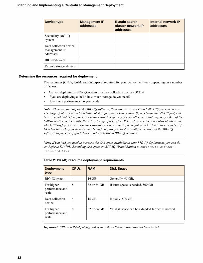
Device type Management IPaddresses
Elastic searchcluster network IPaddresses
Internal network IPaddresses
Secondary BIG-IQsystem
Data collection devicemanagement IPaddresses
BIG-IP devices
Remote storage device
Determine the resources required for deployment
The resources (CPUs, RAM, and disk space) required for your deployment vary depending on a numberof factors.
• Are you deploying a BIG-IQ system or a data collection device (DCD)?• If you are deploying a DCD, how much storage do you need?• How much performance do you need?
Note: When you first deploy the BIG-IQ software, there are two sizes (95 and 500 GB) you can choose.The larger footprint provides additional storage space when needed. If you choose the 500GB footprint,bear in mind that before you can use the extra disk space you must allocate it. Initially, only 95GB of the500GB is allocated. Usually, the extra storage space is for DCDs. However, there are also situations inwhich BIG-IQ systems can use the extra space. For example, you might want to store a large number ofUCS backups. Or, your business needs might require you to store multiple versions of the BIG-IQsoftware so you can upgrade back and forth between BIG-IQ versions.
Note: If you find you need to increase the disk space available to your BIG-IQ deployment, you can doso. Refer to K16103: Extending disk space on BIG-IQ Virtual Edition at support.f5.com/csp/article/K16103.
Table 2: BIG-IQ resource deployment requirements
Deploymenttype
CPUs RAM Disk Space
BIG-IQ system 4 16 GB Generally, 95 GB.
For higherperformance andscale
8 32 or 64 GB If extra space is needed, 500 GB
Data collectiondevice
4 16 GB Initially: 500 GB.
For higherperformance andscale:
8 32 or 64 GB VE disk space can be extended further as needed.
Important: CPU and RAM pairings other than those listed above have not been tested.
Planning and Implementing a Centralized Management Deployment
12
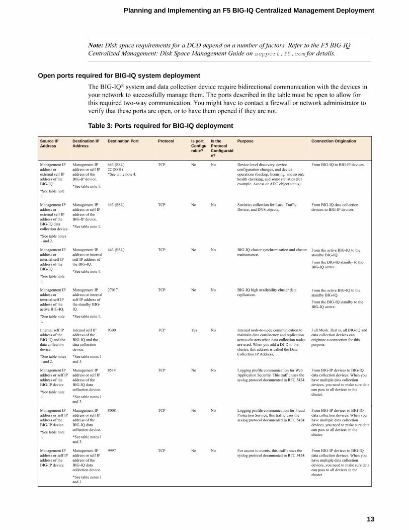
Note: Disk space requirements for a DCD depend on a number of factors. Refer to the F5 BIG-IQCentralized Management: Disk Space Management Guide on support.f5.com for details.
Open ports required for BIG-IQ system deployment
The BIG-IQ® system and data collection device require bidirectional communication with the devices inyour network to successfully manage them. The ports described in the table must be open to allow forthis required two-way communication. You might have to contact a firewall or network administrator toverify that these ports are open, or to have them opened if they are not.
Table 3: Ports required for BIG-IQ deployment
Source IPAddress
Destination IPAddress
Destination Port Protocol Is portConfigurable?
Is theProtocolConfigurable?
Purpose Connection Origination
Management IPaddress orexternal self IPaddress of theBIG-IQ.
*See table note1.
Management IPaddress or self IPaddress of theBIG-IP device.
*See table note 1.
443 (SSL)22 (SSH)*See table note 4.
TCP No No Device-level discovery, deviceconfiguration changes, and deviceoperations (backup, licensing, and so on),health checking, and some statistics (forexample, Access or ADC object status).
From BIG-IQ to BIG-IP devices.
Management IPaddress orexternal self IPaddress of theBIG-IQ datacollection device.
*See table notes1 and 2.
Management IPaddress or self IPaddress of theBIG-IP device.
*See table note 1.
443 (SSL) TCP No No Statistics collection for Local Traffic,Device, and DNS objects.
From BIG-IQ data collectiondevices to BIG-IP devices.
Management IPaddress orinternal self IPaddress of theBIG-IQ.
*See table note1.
Management IPaddress or internalself IP address ofthe BIG-IQ.
*See table note 1.
443 (SSL) TCP No No BIG-IQ cluster synchronization and clustermaintenance.
From the active BIG-IQ to thestandby BIG-IQ.
From the BIG-IQ standby to theBIG-IQ active.
Management IPaddress orinternal self IPaddress of theactive BIG-IQ.
*See table note1.
Management IPaddress or internalself IP address ofthe standby BIG-IQ.
*See table note 1.
27017 TCP No No BIG-IQ high availability cluster datareplication.
From the active BIG-IQ to thestandby BIG-IQ.
From the BIG-IQ standby to theBIG-IQ active.
Internal self IPaddress of theBIG-IQ and thedata collectiondevice.
*See table notes1 and 2.
Internal self IPaddress of theBIG-IQ and thedata collectiondevice.
*See table notes 1and 3.
9300 TCP Yes No Internal node-to-node communication tomaintain data consistency and replicationacross clusters when data collection nodesare used. When you add a DCD to thecluster, this address is called the DataCollection IP Address,
Full Mesh. That is, all BIG-IQ anddata collection devices canoriginate a connection for thispurpose.
Management IPaddress or self IPaddress of theBIG-IP device.
*See table note1.
Management IPaddress or self IPaddress of theBIG-IQ datacollection device.
*See table notes 1and 3.
8514 TCP No No Logging profile communication for WebApplication Security. This traffic uses thesyslog protocol documented in RFC 5424.
From BIG-IP devices to BIG-IQdata collection devices. When youhave multiple data collectiondevices, you need to make sure datacan pass to all devices in thecluster.
Management IPaddress or self IPaddress of theBIG-IP device.
*See table note1.
Management IPaddress or self IPaddress of theBIG-IQ datacollection device.
*See table notes 1and 3.
8008 TCP No No Logging profile communication for FraudProtection Service, this traffic uses thesyslog protocol documented in RFC 5424.
From BIG-IP devices to BIG-IQdata collection devices. When youhave multiple data collectiondevices, you need to make sure datacan pass to all devices in thecluster.
Management IPaddress or self IPaddress of theBIG-IP device.
Management IPaddress or self IPaddress of theBIG-IQ datacollection device.
*See table notes 1and 3.
9997 TCP No No For access to events; this traffic uses thesyslog protocol documented in RFC 5424.
From BIG-IP devices to BIG-IQdata collection devices. When youhave multiple data collectiondevices, you need to make sure datacan pass to all devices in thecluster.
Planning and Implementing an F5 BIG-IQ Centralized Management Deployment
13
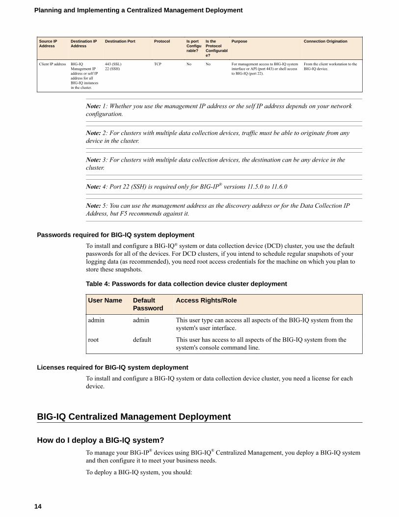
Source IPAddress
Destination IPAddress
Destination Port Protocol Is portConfigurable?
Is theProtocolConfigurable?
Purpose Connection Origination
Client IP address BIG-IQManagement IPaddress or self IPaddress for allBIG-IQ instancesin the cluster.
443 (SSL)22 (SSH)
TCP No No For management access to BIG-IQ systeminterface or API (port 443) or shell accessto BIG-IQ (port 22).
From the client workstation to theBIG-IQ device.
Note: 1: Whether you use the management IP address or the self IP address depends on your networkconfiguration.
Note: 2: For clusters with multiple data collection devices, traffic must be able to originate from anydevice in the cluster.
Note: 3: For clusters with multiple data collection devices, the destination can be any device in thecluster.
Note: 4: Port 22 (SSH) is required only for BIG-IP® versions 11.5.0 to 11.6.0
Note: 5: You can use the management address as the discovery address or for the Data Collection IPAddress, but F5 recommends against it.
Passwords required for BIG-IQ system deployment
To install and configure a BIG-IQ® system or data collection device (DCD) cluster, you use the defaultpasswords for all of the devices. For DCD clusters, if you intend to schedule regular snapshots of yourlogging data (as recommended), you need root access credentials for the machine on which you plan tostore these snapshots.
Table 4: Passwords for data collection device cluster deployment
User Name DefaultPassword
Access Rights/Role
admin admin This user type can access all aspects of the BIG-IQ system from thesystem's user interface.
root default This user has access to all aspects of the BIG-IQ system from thesystem's console command line.
Licenses required for BIG-IQ system deployment
To install and configure a BIG-IQ system or data collection device cluster, you need a license for eachdevice.
BIG-IQ Centralized Management Deployment
How do I deploy a BIG-IQ system?
To manage your BIG-IP® devices using BIG-IQ® Centralized Management, you deploy a BIG-IQ systemand then configure it to meet your business needs.
To deploy a BIG-IQ system, you should:
Planning and Implementing a Centralized Management Deployment
14
• Prepare your network environment• Deploy a BIG-IQ virtual machine or BIG-IQ 7000 Series platform• License and configure the BIG-IQ system• Deploy and configure a second BIG-IQ system for HA, if needed.
How do I license and do the basic setup to start using BIG-IQ?
After you download the software image from the F5 Downloads site and start BIG-IQ® in your virtualenvironment, you can license the system using the base registration key provided by F5. The baseregistration key is a character string the F5 license server uses to provide BIG-IQ a license to access thesubscription licensing feature.
You license BIG-IQ in one of the following ways:
• If the system has access to the Internet, you can have the BIG-IQ system contact the F5 license serverand automatically activate the base registration key to get a license.
• If the system is not connected to the Internet, you can manually license the BIG-IQ using the F5license server web portal.
• If the system is in a closed-circuit network (CCN) that does not allow you to export any encryptedinformation, you must open a case with F5 support at: support.f5.com/csp/my-support/home.
When licensing BIG-IQ, you:
1. Activate the license.2. Accept the EULA.3. Specify the system personality as BIG-IQ Centralized Management.4. Specify a host name, and IP addresses for the management port, DNS server, and network time
protocol (NTP) servers.5. Specify the master key pass phrase.6. Change the default admin and root passwords.
Automatic license and initial setup for a BIG-IQ
You must have a base registration key before you can license the BIG-IQ® system. If you do not have abase registration key, contact the F5 Networks sales group (f5.com).
If the BIG-IQ® system is connected to the public internet, you can follow these steps to automaticallyperform the license activation and perform the initial setup.
1. Use a browser to log in to BIG-IQ by typing https://<management_IP_address>, where<management_IP_address> is the address you specified for device management.
2. In the Base Registration Key field, type or paste the BIG-IQ registration key.
Important: If you are setting up a data collection device, you have to use a registration key thatsupports a data collection device license.
3. In the Add-On Keys field, paste any additional license key you have.4. To add another additional add-on key, click the + sign and paste the additional key in the new Add-
On Keys field.5. For the Activation Method setting, select Automatic, and click the Activate button.6. Click Next.
If you are setting up this device for the first time, the Accept User Legal Agreement screen opens.7. To accept the license agreement, click the Agree button.8. Click the Next button at the bottom of the screen.
If your license supports both BIG-IQ Data Collection Device and BIG-IQ Central ManagementConsole, the System Personality screen displays. Otherwise the Management Address screen opens.
Planning and Implementing an F5 BIG-IQ Centralized Management Deployment
15
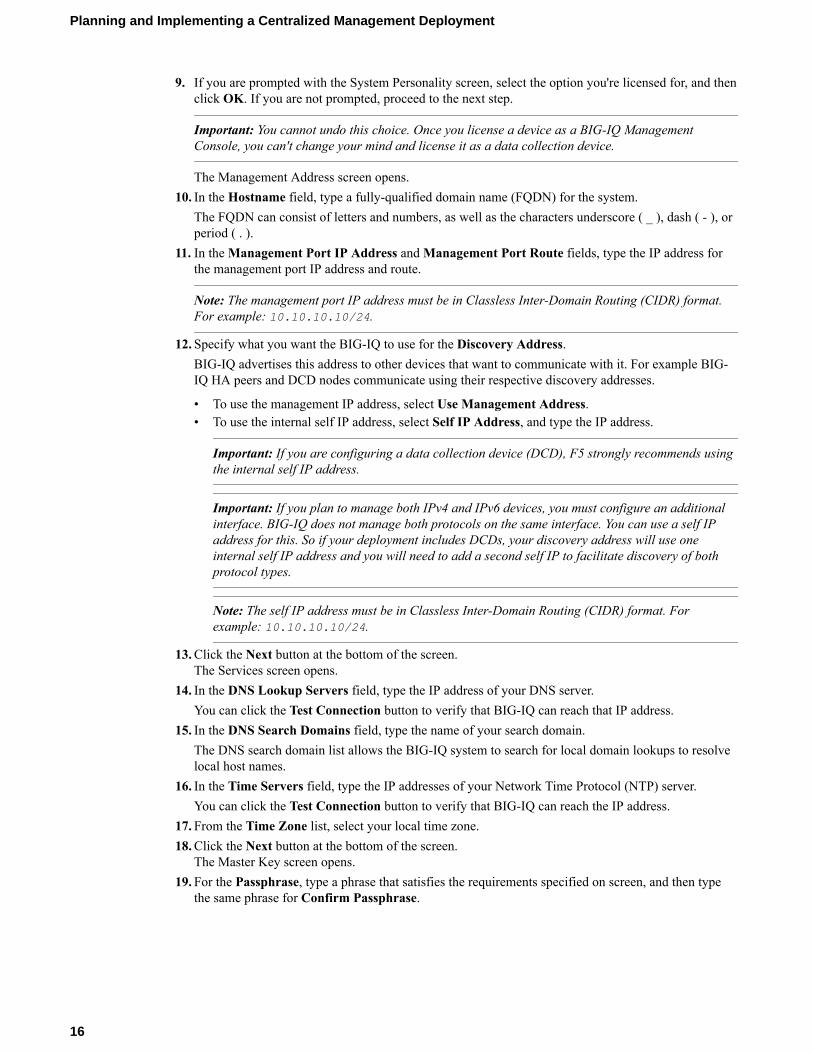
9. If you are prompted with the System Personality screen, select the option you're licensed for, and thenclick OK. If you are not prompted, proceed to the next step.
Important: You cannot undo this choice. Once you license a device as a BIG-IQ ManagementConsole, you can't change your mind and license it as a data collection device.
The Management Address screen opens.10. In the Hostname field, type a fully-qualified domain name (FQDN) for the system.
The FQDN can consist of letters and numbers, as well as the characters underscore ( _ ), dash ( - ), orperiod ( . ).
11. In the Management Port IP Address and Management Port Route fields, type the IP address forthe management port IP address and route.
Note: The management port IP address must be in Classless Inter-Domain Routing (CIDR) format.For example: 10.10.10.10/24.
12. Specify what you want the BIG-IQ to use for the Discovery Address.BIG-IQ advertises this address to other devices that want to communicate with it. For example BIG-IQ HA peers and DCD nodes communicate using their respective discovery addresses.
• To use the management IP address, select Use Management Address.• To use the internal self IP address, select Self IP Address, and type the IP address.
Important: If you are configuring a data collection device (DCD), F5 strongly recommends usingthe internal self IP address.
Important: If you plan to manage both IPv4 and IPv6 devices, you must configure an additionalinterface. BIG-IQ does not manage both protocols on the same interface. You can use a self IPaddress for this. So if your deployment includes DCDs, your discovery address will use oneinternal self IP address and you will need to add a second self IP to facilitate discovery of bothprotocol types.
Note: The self IP address must be in Classless Inter-Domain Routing (CIDR) format. Forexample: 10.10.10.10/24.
13. Click the Next button at the bottom of the screen.The Services screen opens.
14. In the DNS Lookup Servers field, type the IP address of your DNS server.You can click the Test Connection button to verify that BIG-IQ can reach that IP address.
15. In the DNS Search Domains field, type the name of your search domain.The DNS search domain list allows the BIG-IQ system to search for local domain lookups to resolvelocal host names.
16. In the Time Servers field, type the IP addresses of your Network Time Protocol (NTP) server.You can click the Test Connection button to verify that BIG-IQ can reach the IP address.
17. From the Time Zone list, select your local time zone.18. Click the Next button at the bottom of the screen.
The Master Key screen opens.19. For the Passphrase, type a phrase that satisfies the requirements specified on screen, and then type
the same phrase for Confirm Passphrase.
Planning and Implementing a Centralized Management Deployment
16
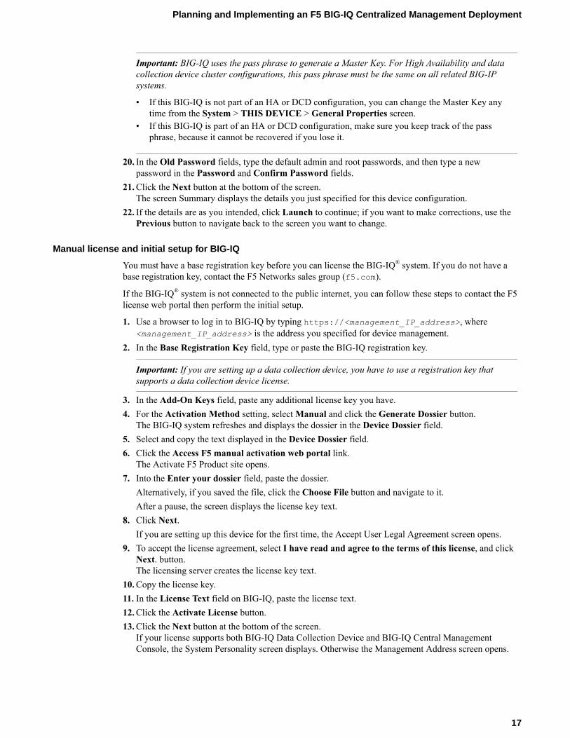
Important: BIG-IQ uses the pass phrase to generate a Master Key. For High Availability and datacollection device cluster configurations, this pass phrase must be the same on all related BIG-IPsystems.
• If this BIG-IQ is not part of an HA or DCD configuration, you can change the Master Key anytime from the System > THIS DEVICE > General Properties screen.
• If this BIG-IQ is part of an HA or DCD configuration, make sure you keep track of the passphrase, because it cannot be recovered if you lose it.
20. In the Old Password fields, type the default admin and root passwords, and then type a newpassword in the Password and Confirm Password fields.
21. Click the Next button at the bottom of the screen.The screen Summary displays the details you just specified for this device configuration.
22. If the details are as you intended, click Launch to continue; if you want to make corrections, use thePrevious button to navigate back to the screen you want to change.
Manual license and initial setup for BIG-IQ
You must have a base registration key before you can license the BIG-IQ® system. If you do not have abase registration key, contact the F5 Networks sales group (f5.com).
If the BIG-IQ® system is not connected to the public internet, you can follow these steps to contact the F5license web portal then perform the initial setup.
1. Use a browser to log in to BIG-IQ by typing https://<management_IP_address>, where<management_IP_address> is the address you specified for device management.
2. In the Base Registration Key field, type or paste the BIG-IQ registration key.
Important: If you are setting up a data collection device, you have to use a registration key thatsupports a data collection device license.
3. In the Add-On Keys field, paste any additional license key you have.4. For the Activation Method setting, select Manual and click the Generate Dossier button.
The BIG-IQ system refreshes and displays the dossier in the Device Dossier field.5. Select and copy the text displayed in the Device Dossier field.6. Click the Access F5 manual activation web portal link.
The Activate F5 Product site opens.7. Into the Enter your dossier field, paste the dossier.
Alternatively, if you saved the file, click the Choose File button and navigate to it.After a pause, the screen displays the license key text.
8. Click Next.If you are setting up this device for the first time, the Accept User Legal Agreement screen opens.
9. To accept the license agreement, select I have read and agree to the terms of this license, and clickNext. button.The licensing server creates the license key text.
10. Copy the license key.11. In the License Text field on BIG-IQ, paste the license text.12. Click the Activate License button.13. Click the Next button at the bottom of the screen.
If your license supports both BIG-IQ Data Collection Device and BIG-IQ Central ManagementConsole, the System Personality screen displays. Otherwise the Management Address screen opens.
Planning and Implementing an F5 BIG-IQ Centralized Management Deployment
17

14. If you are prompted with the System Personality screen, select the option you're licensed for, and thenclick OK. If you are not prompted, proceed to the next step.
Important: You cannot undo this choice. Once you license a device as a BIG-IQ ManagementConsole, you can't change your mind and license it as a data collection device.
The Management Address screen opens.15. In the Hostname field, type a fully-qualified domain name (FQDN) for the system.
The FQDN can consist of letters and numbers, as well as the characters underscore ( _ ), dash ( - ), orperiod ( . ).
16. In the Management Port IP Address and Management Port Route fields, type the IP address forthe management port IP address and route.
Note: The management port IP address must be in Classless Inter-Domain Routing (CIDR) format.For example: 10.10.10.10/24.
17. Specify what you want the BIG-IQ to use for the Discovery Address.BIG-IQ advertises this address to other devices that want to communicate with it. For example BIG-IQ HA peers and DCD nodes communicate using their respective discovery addresses.
• To use the management IP address, select Use Management Address.• To use the internal self IP address, select Self IP Address, and type the IP address.
Important: If you are configuring a data collection device (DCD), F5 strongly recommends usingthe internal self IP address.
Important: If you plan to manage both IPv4 and IPv6 devices, you must configure an additionalinterface. BIG-IQ does not manage both protocols on the same interface. You can use a self IPaddress for this. So if your deployment includes DCDs, your discovery address will use oneinternal self IP address and you will need to add a second self IP to facilitate discovery of bothprotocol types.
Note: The self IP address must be in Classless Inter-Domain Routing (CIDR) format. Forexample: 10.10.10.10/24.
18. Click the Next button at the bottom of the screen.The Services screen opens.
19. In the DNS Lookup Servers field, type the IP address of your DNS server.You can click the Test Connection button to verify that BIG-IQ can reach that IP address.
20. In the DNS Search Domains field, type the name of your search domain.The DNS search domain list allows the BIG-IQ system to search for local domain lookups to resolvelocal host names.
21. In the Time Servers field, type the IP addresses of your Network Time Protocol (NTP) server.You can click the Test Connection button to verify that BIG-IQ can reach the IP address.
22. From the Time Zone list, select your local time zone.23. Click the Next button at the bottom of the screen.
The Master Key screen opens.24. For the Passphrase, type a phrase that satisfies the requirements specified on screen, and then type
the same phrase for Confirm Passphrase.
Planning and Implementing a Centralized Management Deployment
18
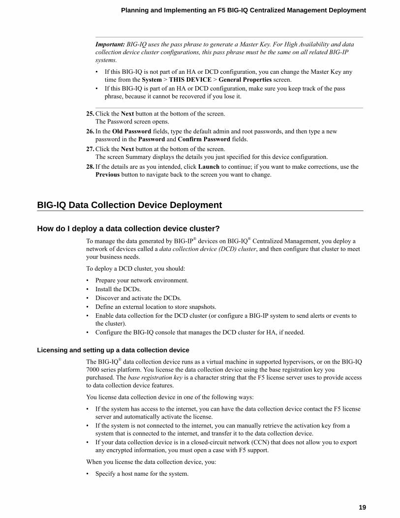
Important: BIG-IQ uses the pass phrase to generate a Master Key. For High Availability and datacollection device cluster configurations, this pass phrase must be the same on all related BIG-IPsystems.
• If this BIG-IQ is not part of an HA or DCD configuration, you can change the Master Key anytime from the System > THIS DEVICE > General Properties screen.
• If this BIG-IQ is part of an HA or DCD configuration, make sure you keep track of the passphrase, because it cannot be recovered if you lose it.
25. Click the Next button at the bottom of the screen.The Password screen opens.
26. In the Old Password fields, type the default admin and root passwords, and then type a newpassword in the Password and Confirm Password fields.
27. Click the Next button at the bottom of the screen.The screen Summary displays the details you just specified for this device configuration.
28. If the details are as you intended, click Launch to continue; if you want to make corrections, use thePrevious button to navigate back to the screen you want to change.
BIG-IQ Data Collection Device Deployment
How do I deploy a data collection device cluster?
To manage the data generated by BIG-IP® devices on BIG-IQ® Centralized Management, you deploy anetwork of devices called a data collection device (DCD) cluster, and then configure that cluster to meetyour business needs.
To deploy a DCD cluster, you should:
• Prepare your network environment.• Install the DCDs.• Discover and activate the DCDs.• Define an external location to store snapshots.• Enable data collection for the DCD cluster (or configure a BIG-IP system to send alerts or events to
the cluster).• Configure the BIG-IQ console that manages the DCD cluster for HA, if needed.
Licensing and setting up a data collection device
The BIG-IQ® data collection device runs as a virtual machine in supported hypervisors, or on the BIG-IQ7000 series platform. You license the data collection device using the base registration key youpurchased. The base registration key is a character string that the F5 license server uses to provide accessto data collection device features.
You license data collection device in one of the following ways:
• If the system has access to the internet, you can have the data collection device contact the F5 licenseserver and automatically activate the license.
• If the system is not connected to the internet, you can manually retrieve the activation key from asystem that is connected to the internet, and transfer it to the data collection device.
• If your data collection device is in a closed-circuit network (CCN) that does not allow you to exportany encrypted information, you must open a case with F5 support.
When you license the data collection device, you:
• Specify a host name for the system.
Planning and Implementing an F5 BIG-IQ Centralized Management Deployment
19
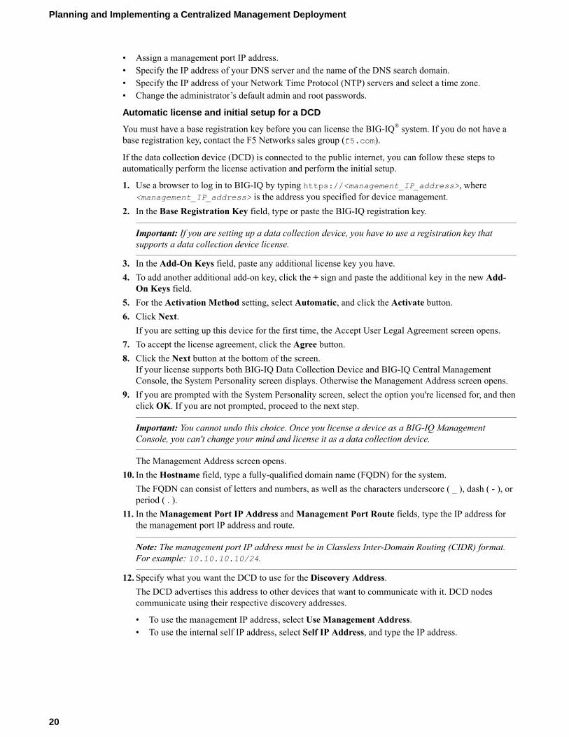
• Assign a management port IP address.• Specify the IP address of your DNS server and the name of the DNS search domain.• Specify the IP address of your Network Time Protocol (NTP) servers and select a time zone.• Change the administrator’s default admin and root passwords.
Automatic license and initial setup for a DCD
You must have a base registration key before you can license the BIG-IQ® system. If you do not have abase registration key, contact the F5 Networks sales group (f5.com).
If the data collection device (DCD) is connected to the public internet, you can follow these steps toautomatically perform the license activation and perform the initial setup.
1. Use a browser to log in to BIG-IQ by typing https://<management_IP_address>, where<management_IP_address> is the address you specified for device management.
2. In the Base Registration Key field, type or paste the BIG-IQ registration key.
Important: If you are setting up a data collection device, you have to use a registration key thatsupports a data collection device license.
3. In the Add-On Keys field, paste any additional license key you have.4. To add another additional add-on key, click the + sign and paste the additional key in the new Add-
On Keys field.5. For the Activation Method setting, select Automatic, and click the Activate button.6. Click Next.
If you are setting up this device for the first time, the Accept User Legal Agreement screen opens.7. To accept the license agreement, click the Agree button.8. Click the Next button at the bottom of the screen.
If your license supports both BIG-IQ Data Collection Device and BIG-IQ Central ManagementConsole, the System Personality screen displays. Otherwise the Management Address screen opens.
9. If you are prompted with the System Personality screen, select the option you're licensed for, and thenclick OK. If you are not prompted, proceed to the next step.
Important: You cannot undo this choice. Once you license a device as a BIG-IQ ManagementConsole, you can't change your mind and license it as a data collection device.
The Management Address screen opens.10. In the Hostname field, type a fully-qualified domain name (FQDN) for the system.
The FQDN can consist of letters and numbers, as well as the characters underscore ( _ ), dash ( - ), orperiod ( . ).
11. In the Management Port IP Address and Management Port Route fields, type the IP address forthe management port IP address and route.
Note: The management port IP address must be in Classless Inter-Domain Routing (CIDR) format.For example: 10.10.10.10/24.
12. Specify what you want the DCD to use for the Discovery Address.The DCD advertises this address to other devices that want to communicate with it. DCD nodescommunicate using their respective discovery addresses.
• To use the management IP address, select Use Management Address.• To use the internal self IP address, select Self IP Address, and type the IP address.
Planning and Implementing a Centralized Management Deployment
20
Important: F5 strongly recommends using the internal self IP address as the Discovery Addressfor a DCD.
Note: The self IP address must be in Classless Inter-Domain Routing (CIDR) format. Forexample: 10.10.10.10/24.
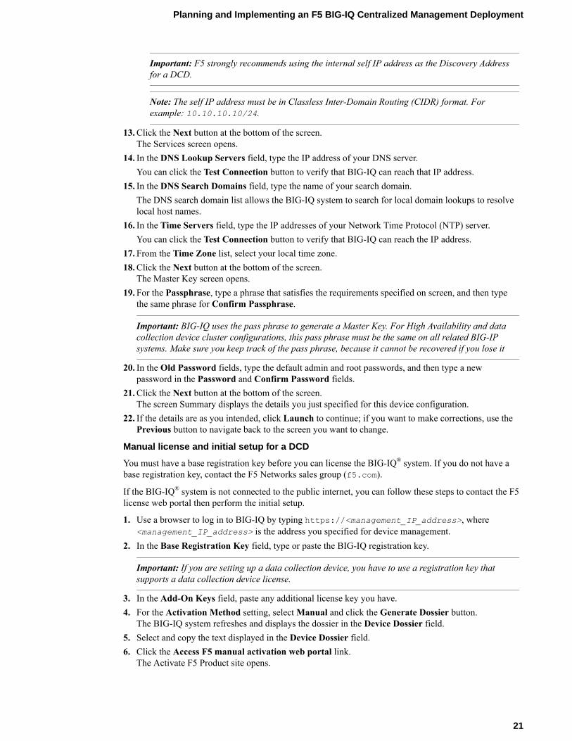
13. Click the Next button at the bottom of the screen.The Services screen opens.
14. In the DNS Lookup Servers field, type the IP address of your DNS server.You can click the Test Connection button to verify that BIG-IQ can reach that IP address.
15. In the DNS Search Domains field, type the name of your search domain.The DNS search domain list allows the BIG-IQ system to search for local domain lookups to resolvelocal host names.
16. In the Time Servers field, type the IP addresses of your Network Time Protocol (NTP) server.You can click the Test Connection button to verify that BIG-IQ can reach the IP address.
17. From the Time Zone list, select your local time zone.18. Click the Next button at the bottom of the screen.
The Master Key screen opens.19. For the Passphrase, type a phrase that satisfies the requirements specified on screen, and then type
the same phrase for Confirm Passphrase.
Important: BIG-IQ uses the pass phrase to generate a Master Key. For High Availability and datacollection device cluster configurations, this pass phrase must be the same on all related BIG-IPsystems. Make sure you keep track of the pass phrase, because it cannot be recovered if you lose it
20. In the Old Password fields, type the default admin and root passwords, and then type a newpassword in the Password and Confirm Password fields.
21. Click the Next button at the bottom of the screen.The screen Summary displays the details you just specified for this device configuration.
22. If the details are as you intended, click Launch to continue; if you want to make corrections, use thePrevious button to navigate back to the screen you want to change.
Manual license and initial setup for a DCD
You must have a base registration key before you can license the BIG-IQ® system. If you do not have abase registration key, contact the F5 Networks sales group (f5.com).
If the BIG-IQ® system is not connected to the public internet, you can follow these steps to contact the F5license web portal then perform the initial setup.
1. Use a browser to log in to BIG-IQ by typing https://<management_IP_address>, where<management_IP_address> is the address you specified for device management.
2. In the Base Registration Key field, type or paste the BIG-IQ registration key.
Important: If you are setting up a data collection device, you have to use a registration key thatsupports a data collection device license.
3. In the Add-On Keys field, paste any additional license key you have.4. For the Activation Method setting, select Manual and click the Generate Dossier button.
The BIG-IQ system refreshes and displays the dossier in the Device Dossier field.5. Select and copy the text displayed in the Device Dossier field.6. Click the Access F5 manual activation web portal link.
The Activate F5 Product site opens.
Planning and Implementing an F5 BIG-IQ Centralized Management Deployment
21
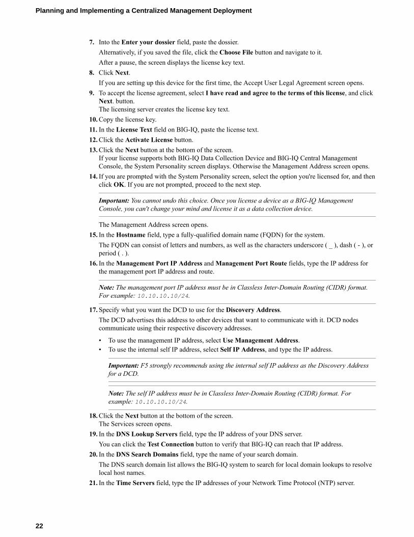
7. Into the Enter your dossier field, paste the dossier.Alternatively, if you saved the file, click the Choose File button and navigate to it.After a pause, the screen displays the license key text.
8. Click Next.If you are setting up this device for the first time, the Accept User Legal Agreement screen opens.
9. To accept the license agreement, select I have read and agree to the terms of this license, and clickNext. button.The licensing server creates the license key text.
10. Copy the license key.11. In the License Text field on BIG-IQ, paste the license text.12. Click the Activate License button.13. Click the Next button at the bottom of the screen.
If your license supports both BIG-IQ Data Collection Device and BIG-IQ Central ManagementConsole, the System Personality screen displays. Otherwise the Management Address screen opens.
14. If you are prompted with the System Personality screen, select the option you're licensed for, and thenclick OK. If you are not prompted, proceed to the next step.
Important: You cannot undo this choice. Once you license a device as a BIG-IQ ManagementConsole, you can't change your mind and license it as a data collection device.
The Management Address screen opens.15. In the Hostname field, type a fully-qualified domain name (FQDN) for the system.
The FQDN can consist of letters and numbers, as well as the characters underscore ( _ ), dash ( - ), orperiod ( . ).
16. In the Management Port IP Address and Management Port Route fields, type the IP address forthe management port IP address and route.
Note: The management port IP address must be in Classless Inter-Domain Routing (CIDR) format.For example: 10.10.10.10/24.
17. Specify what you want the DCD to use for the Discovery Address.The DCD advertises this address to other devices that want to communicate with it. DCD nodescommunicate using their respective discovery addresses.
• To use the management IP address, select Use Management Address.• To use the internal self IP address, select Self IP Address, and type the IP address.
Important: F5 strongly recommends using the internal self IP address as the Discovery Addressfor a DCD.
Note: The self IP address must be in Classless Inter-Domain Routing (CIDR) format. Forexample: 10.10.10.10/24.
18. Click the Next button at the bottom of the screen.The Services screen opens.
19. In the DNS Lookup Servers field, type the IP address of your DNS server.You can click the Test Connection button to verify that BIG-IQ can reach that IP address.
20. In the DNS Search Domains field, type the name of your search domain.The DNS search domain list allows the BIG-IQ system to search for local domain lookups to resolvelocal host names.
21. In the Time Servers field, type the IP addresses of your Network Time Protocol (NTP) server.
Planning and Implementing a Centralized Management Deployment
22
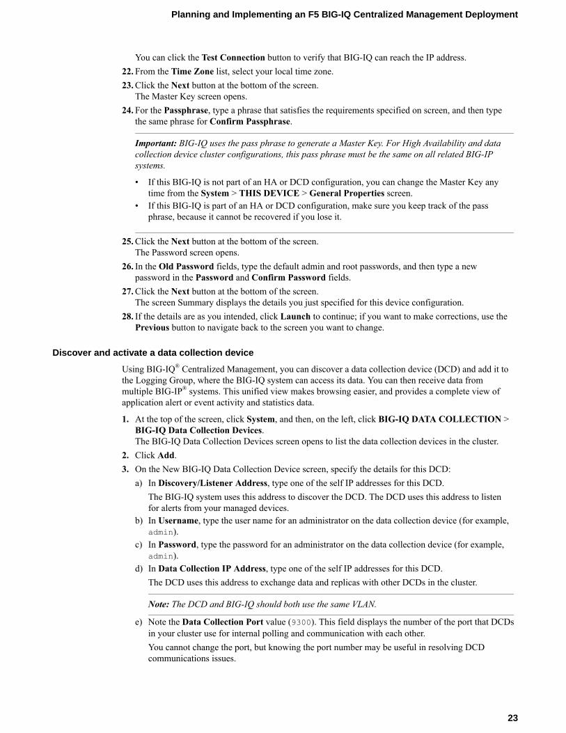
You can click the Test Connection button to verify that BIG-IQ can reach the IP address.22. From the Time Zone list, select your local time zone.23. Click the Next button at the bottom of the screen.
The Master Key screen opens.24. For the Passphrase, type a phrase that satisfies the requirements specified on screen, and then type
the same phrase for Confirm Passphrase.
Important: BIG-IQ uses the pass phrase to generate a Master Key. For High Availability and datacollection device cluster configurations, this pass phrase must be the same on all related BIG-IPsystems.
• If this BIG-IQ is not part of an HA or DCD configuration, you can change the Master Key anytime from the System > THIS DEVICE > General Properties screen.
• If this BIG-IQ is part of an HA or DCD configuration, make sure you keep track of the passphrase, because it cannot be recovered if you lose it.
25. Click the Next button at the bottom of the screen.The Password screen opens.
26. In the Old Password fields, type the default admin and root passwords, and then type a newpassword in the Password and Confirm Password fields.
27. Click the Next button at the bottom of the screen.The screen Summary displays the details you just specified for this device configuration.
28. If the details are as you intended, click Launch to continue; if you want to make corrections, use thePrevious button to navigate back to the screen you want to change.
Discover and activate a data collection device
Using BIG-IQ® Centralized Management, you can discover a data collection device (DCD) and add it tothe Logging Group, where the BIG-IQ system can access its data. You can then receive data frommultiple BIG-IP® systems. This unified view makes browsing easier, and provides a complete view ofapplication alert or event activity and statistics data.
1. At the top of the screen, click System, and then, on the left, click BIG-IQ DATA COLLECTION >BIG-IQ Data Collection Devices.The BIG-IQ Data Collection Devices screen opens to list the data collection devices in the cluster.
2. Click Add.3. On the New BIG-IQ Data Collection Device screen, specify the details for this DCD:
a) In Discovery/Listener Address, type one of the self IP addresses for this DCD.The BIG-IQ system uses this address to discover the DCD. The DCD uses this address to listenfor alerts from your managed devices.
b) In Username, type the user name for an administrator on the data collection device (for example,admin).
c) In Password, type the password for an administrator on the data collection device (for example,admin).
d) In Data Collection IP Address, type one of the self IP addresses for this DCD.The DCD uses this address to exchange data and replicas with other DCDs in the cluster.
Note: The DCD and BIG-IQ should both use the same VLAN.
e) Note the Data Collection Port value (9300). This field displays the number of the port that DCDsin your cluster use for internal polling and communication with each other.You cannot change the port, but knowing the port number may be useful in resolving DCDcommunications issues.
Planning and Implementing an F5 BIG-IQ Centralized Management Deployment
23
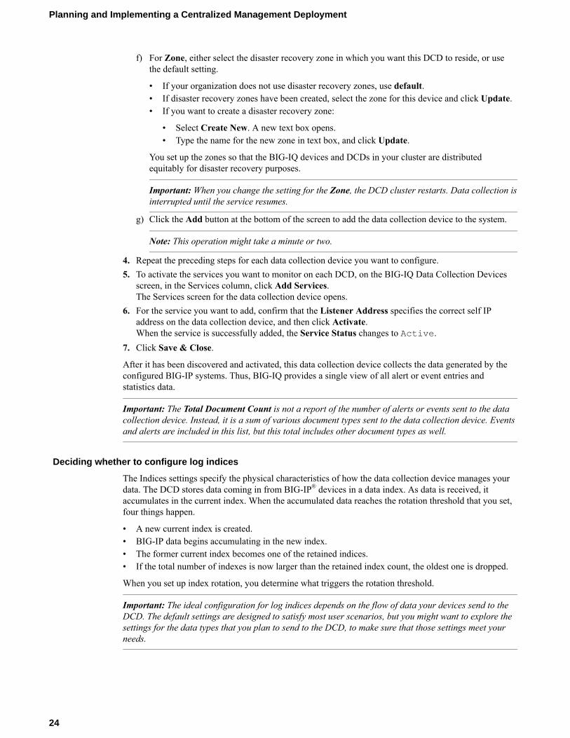
f) For Zone, either select the disaster recovery zone in which you want this DCD to reside, or usethe default setting.
• If your organization does not use disaster recovery zones, use default.• If disaster recovery zones have been created, select the zone for this device and click Update.• If you want to create a disaster recovery zone:
• Select Create New. A new text box opens.• Type the name for the new zone in text box, and click Update.
You set up the zones so that the BIG-IQ devices and DCDs in your cluster are distributedequitably for disaster recovery purposes.
Important: When you change the setting for the Zone, the DCD cluster restarts. Data collection isinterrupted until the service resumes.
g) Click the Add button at the bottom of the screen to add the data collection device to the system.
Note: This operation might take a minute or two.
4. Repeat the preceding steps for each data collection device you want to configure.5. To activate the services you want to monitor on each DCD, on the BIG-IQ Data Collection Devices
screen, in the Services column, click Add Services.The Services screen for the data collection device opens.
6. For the service you want to add, confirm that the Listener Address specifies the correct self IPaddress on the data collection device, and then click Activate.When the service is successfully added, the Service Status changes to Active.
7. Click Save & Close.
After it has been discovered and activated, this data collection device collects the data generated by theconfigured BIG-IP systems. Thus, BIG-IQ provides a single view of all alert or event entries andstatistics data.
Important: The Total Document Count is not a report of the number of alerts or events sent to the datacollection device. Instead, it is a sum of various document types sent to the data collection device. Eventsand alerts are included in this list, but this total includes other document types as well.
Deciding whether to configure log indices
The Indices settings specify the physical characteristics of how the data collection device manages yourdata. The DCD stores data coming in from BIG-IP® devices in a data index. As data is received, itaccumulates in the current index. When the accumulated data reaches the rotation threshold that you set,four things happen.
• A new current index is created.• BIG-IP data begins accumulating in the new index.• The former current index becomes one of the retained indices.• If the total number of indexes is now larger than the retained index count, the oldest one is dropped.
When you set up index rotation, you determine what triggers the rotation threshold.
Important: The ideal configuration for log indices depends on the flow of data your devices send to theDCD. The default settings are designed to satisfy most user scenarios, but you might want to explore thesettings for the data types that you plan to send to the DCD, to make sure that those settings meet yourneeds.
Planning and Implementing a Centralized Management Deployment
24
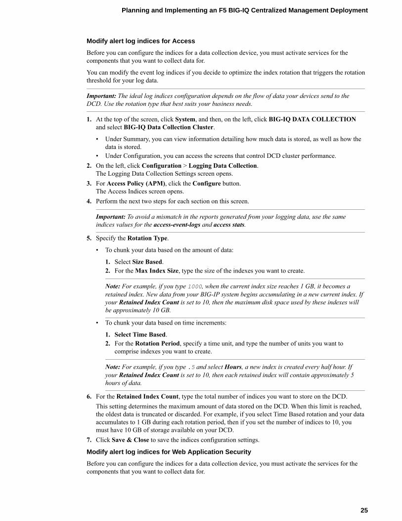
Modify alert log indices for Access
Before you can configure the indices for a data collection device, you must activate services for thecomponents that you want to collect data for.
You can modify the event log indices if you decide to optimize the index rotation that triggers the rotationthreshold for your log data.
Important: The ideal log indices configuration depends on the flow of data your devices send to theDCD. Use the rotation type that best suits your business needs.
1. At the top of the screen, click System, and then, on the left, click BIG-IQ DATA COLLECTIONand select BIG-IQ Data Collection Cluster.
• Under Summary, you can view information detailing how much data is stored, as well as how thedata is stored.
• Under Configuration, you can access the screens that control DCD cluster performance.2. On the left, click Configuration > Logging Data Collection.
The Logging Data Collection Settings screen opens.3. For Access Policy (APM), click the Configure button.
The Access Indices screen opens.4. Perform the next two steps for each section on this screen.
Important: To avoid a mismatch in the reports generated from your logging data, use the sameindices values for the access-event-logs and access stats.
5. Specify the Rotation Type.
• To chunk your data based on the amount of data:
1. Select Size Based.2. For the Max Index Size, type the size of the indexes you want to create.
Note: For example, if you type 1000, when the current index size reaches 1 GB, it becomes aretained index. New data from your BIG-IP system begins accumulating in a new current index. Ifyour Retained Index Count is set to 10, then the maximum disk space used by these indexes willbe approximately 10 GB.
• To chunk your data based on time increments:
1. Select Time Based.2. For the Rotation Period, specify a time unit, and type the number of units you want to
comprise indexes you want to create.
Note: For example, if you type .5 and select Hours, a new index is created every half hour. Ifyour Retained Index Count is set to 10, then each retained index will contain approximately 5hours of data.
6. For the Retained Index Count, type the total number of indices you want to store on the DCD.This setting determines the maximum amount of data stored on the DCD. When this limit is reached,the oldest data is truncated or discarded. For example, if you select Time Based rotation and your dataaccumulates to 1 GB during each rotation period, then if you set the number of indices to 10, youmust have 10 GB of storage available on your DCD.
7. Click Save & Close to save the indices configuration settings.
Modify alert log indices for Web Application Security
Before you can configure the indices for a data collection device, you must activate the services for thecomponents that you want to collect data for.
Planning and Implementing an F5 BIG-IQ Centralized Management Deployment
25
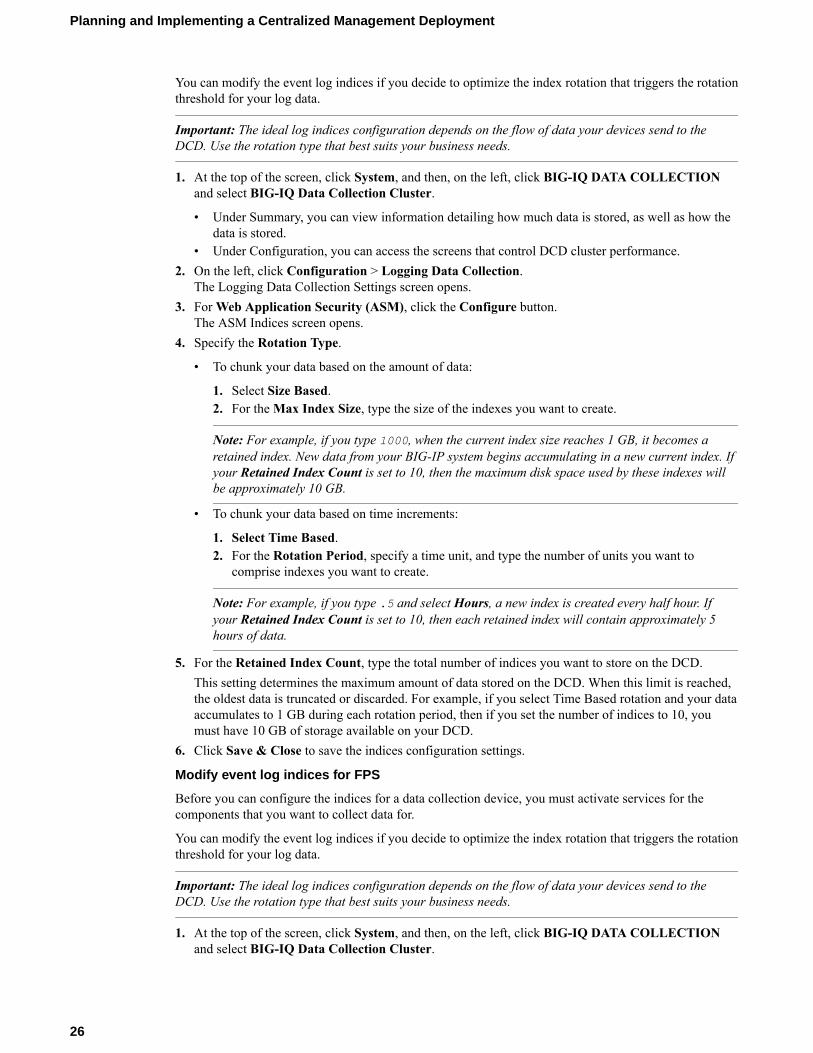
You can modify the event log indices if you decide to optimize the index rotation that triggers the rotationthreshold for your log data.
Important: The ideal log indices configuration depends on the flow of data your devices send to theDCD. Use the rotation type that best suits your business needs.
1. At the top of the screen, click System, and then, on the left, click BIG-IQ DATA COLLECTIONand select BIG-IQ Data Collection Cluster.
• Under Summary, you can view information detailing how much data is stored, as well as how thedata is stored.
• Under Configuration, you can access the screens that control DCD cluster performance.2. On the left, click Configuration > Logging Data Collection.
The Logging Data Collection Settings screen opens.3. For Web Application Security (ASM), click the Configure button.
The ASM Indices screen opens.4. Specify the Rotation Type.
• To chunk your data based on the amount of data:
1. Select Size Based.2. For the Max Index Size, type the size of the indexes you want to create.
Note: For example, if you type 1000, when the current index size reaches 1 GB, it becomes aretained index. New data from your BIG-IP system begins accumulating in a new current index. Ifyour Retained Index Count is set to 10, then the maximum disk space used by these indexes willbe approximately 10 GB.
• To chunk your data based on time increments:
1. Select Time Based.2. For the Rotation Period, specify a time unit, and type the number of units you want to
comprise indexes you want to create.
Note: For example, if you type .5 and select Hours, a new index is created every half hour. Ifyour Retained Index Count is set to 10, then each retained index will contain approximately 5hours of data.
5. For the Retained Index Count, type the total number of indices you want to store on the DCD.This setting determines the maximum amount of data stored on the DCD. When this limit is reached,the oldest data is truncated or discarded. For example, if you select Time Based rotation and your dataaccumulates to 1 GB during each rotation period, then if you set the number of indices to 10, youmust have 10 GB of storage available on your DCD.
6. Click Save & Close to save the indices configuration settings.
Modify event log indices for FPS
Before you can configure the indices for a data collection device, you must activate services for thecomponents that you want to collect data for.
You can modify the event log indices if you decide to optimize the index rotation that triggers the rotationthreshold for your log data.
Important: The ideal log indices configuration depends on the flow of data your devices send to theDCD. Use the rotation type that best suits your business needs.
1. At the top of the screen, click System, and then, on the left, click BIG-IQ DATA COLLECTIONand select BIG-IQ Data Collection Cluster.
Planning and Implementing a Centralized Management Deployment
26
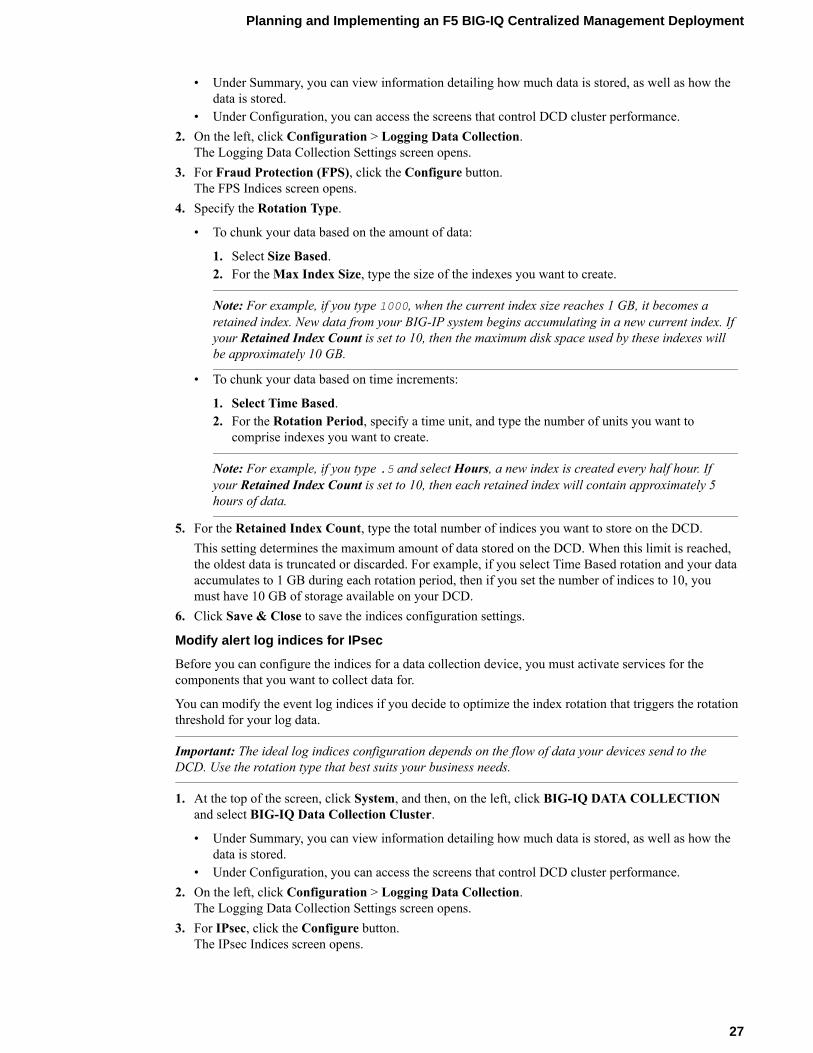
• Under Summary, you can view information detailing how much data is stored, as well as how thedata is stored.
• Under Configuration, you can access the screens that control DCD cluster performance.2. On the left, click Configuration > Logging Data Collection.
The Logging Data Collection Settings screen opens.3. For Fraud Protection (FPS), click the Configure button.
The FPS Indices screen opens.4. Specify the Rotation Type.
• To chunk your data based on the amount of data:
1. Select Size Based.2. For the Max Index Size, type the size of the indexes you want to create.
Note: For example, if you type 1000, when the current index size reaches 1 GB, it becomes aretained index. New data from your BIG-IP system begins accumulating in a new current index. Ifyour Retained Index Count is set to 10, then the maximum disk space used by these indexes willbe approximately 10 GB.
• To chunk your data based on time increments:
1. Select Time Based.2. For the Rotation Period, specify a time unit, and type the number of units you want to
comprise indexes you want to create.
Note: For example, if you type .5 and select Hours, a new index is created every half hour. Ifyour Retained Index Count is set to 10, then each retained index will contain approximately 5hours of data.
5. For the Retained Index Count, type the total number of indices you want to store on the DCD.This setting determines the maximum amount of data stored on the DCD. When this limit is reached,the oldest data is truncated or discarded. For example, if you select Time Based rotation and your dataaccumulates to 1 GB during each rotation period, then if you set the number of indices to 10, youmust have 10 GB of storage available on your DCD.
6. Click Save & Close to save the indices configuration settings.
Modify alert log indices for IPsec
Before you can configure the indices for a data collection device, you must activate services for thecomponents that you want to collect data for.
You can modify the event log indices if you decide to optimize the index rotation that triggers the rotationthreshold for your log data.
Important: The ideal log indices configuration depends on the flow of data your devices send to theDCD. Use the rotation type that best suits your business needs.
1. At the top of the screen, click System, and then, on the left, click BIG-IQ DATA COLLECTIONand select BIG-IQ Data Collection Cluster.
• Under Summary, you can view information detailing how much data is stored, as well as how thedata is stored.
• Under Configuration, you can access the screens that control DCD cluster performance.2. On the left, click Configuration > Logging Data Collection.
The Logging Data Collection Settings screen opens.3. For IPsec, click the Configure button.
The IPsec Indices screen opens.
Planning and Implementing an F5 BIG-IQ Centralized Management Deployment
27
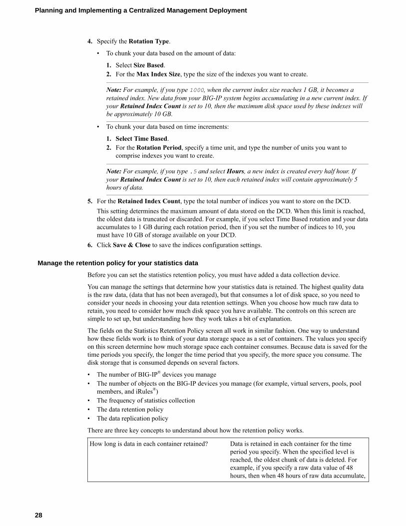
4. Specify the Rotation Type.
• To chunk your data based on the amount of data:
1. Select Size Based.2. For the Max Index Size, type the size of the indexes you want to create.
Note: For example, if you type 1000, when the current index size reaches 1 GB, it becomes aretained index. New data from your BIG-IP system begins accumulating in a new current index. Ifyour Retained Index Count is set to 10, then the maximum disk space used by these indexes willbe approximately 10 GB.
• To chunk your data based on time increments:
1. Select Time Based.2. For the Rotation Period, specify a time unit, and type the number of units you want to
comprise indexes you want to create.
Note: For example, if you type .5 and select Hours, a new index is created every half hour. Ifyour Retained Index Count is set to 10, then each retained index will contain approximately 5hours of data.
5. For the Retained Index Count, type the total number of indices you want to store on the DCD.This setting determines the maximum amount of data stored on the DCD. When this limit is reached,the oldest data is truncated or discarded. For example, if you select Time Based rotation and your dataaccumulates to 1 GB during each rotation period, then if you set the number of indices to 10, youmust have 10 GB of storage available on your DCD.
6. Click Save & Close to save the indices configuration settings.
Manage the retention policy for your statistics data
Before you can set the statistics retention policy, you must have added a data collection device.
You can manage the settings that determine how your statistics data is retained. The highest quality datais the raw data, (data that has not been averaged), but that consumes a lot of disk space, so you need toconsider your needs in choosing your data retention settings. When you choose how much raw data toretain, you need to consider how much disk space you have available. The controls on this screen aresimple to set up, but understanding how they work takes a bit of explanation.
The fields on the Statistics Retention Policy screen all work in similar fashion. One way to understandhow these fields work is to think of your data storage space as a set of containers. The values you specifyon this screen determine how much storage space each container consumes. Because data is saved for thetime periods you specify, the longer the time period that you specify, the more space you consume. Thedisk storage that is consumed depends on several factors.
• The number of BIG-IP® devices you manage• The number of objects on the BIG-IP devices you manage (for example, virtual servers, pools, pool
members, and iRules®)• The frequency of statistics collection• The data retention policy• The data replication policy
There are three key concepts to understand about how the retention policy works.
How long is data in each container retained? Data is retained in each container for the timeperiod you specify. When the specified level isreached, the oldest chunk of data is deleted. Forexample, if you specify a raw data value of 48hours, then when 48 hours of raw data accumulate,
Planning and Implementing a Centralized Management Deployment
28
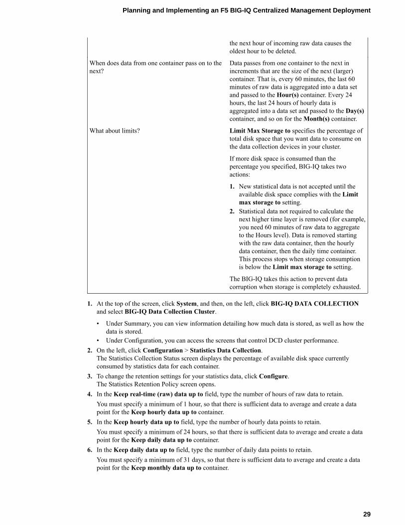
the next hour of incoming raw data causes theoldest hour to be deleted.
When does data from one container pass on to thenext?
Data passes from one container to the next inincrements that are the size of the next (larger)container. That is, every 60 minutes, the last 60minutes of raw data is aggregated into a data setand passed to the Hour(s) container. Every 24hours, the last 24 hours of hourly data isaggregated into a data set and passed to the Day(s)container, and so on for the Month(s) container.
What about limits? Limit Max Storage to specifies the percentage oftotal disk space that you want data to consume onthe data collection devices in your cluster.
If more disk space is consumed than thepercentage you specified, BIG-IQ takes twoactions:
1. New statistical data is not accepted until theavailable disk space complies with the Limitmax storage to setting.
2. Statistical data not required to calculate thenext higher time layer is removed (for example,you need 60 minutes of raw data to aggregateto the Hours level). Data is removed startingwith the raw data container, then the hourlydata container, then the daily time container.This process stops when storage consumptionis below the Limit max storage to setting.
The BIG-IQ takes this action to prevent datacorruption when storage is completely exhausted.
1. At the top of the screen, click System, and then, on the left, click BIG-IQ DATA COLLECTIONand select BIG-IQ Data Collection Cluster.
• Under Summary, you can view information detailing how much data is stored, as well as how thedata is stored.
• Under Configuration, you can access the screens that control DCD cluster performance.2. On the left, click Configuration > Statistics Data Collection.
The Statistics Collection Status screen displays the percentage of available disk space currentlyconsumed by statistics data for each container.
3. To change the retention settings for your statistics data, click Configure.The Statistics Retention Policy screen opens.
4. In the Keep real-time (raw) data up to field, type the number of hours of raw data to retain.You must specify a minimum of 1 hour, so that there is sufficient data to average and create a datapoint for the Keep hourly data up to container.
5. In the Keep hourly data up to field, type the number of hourly data points to retain.You must specify a minimum of 24 hours, so that there is sufficient data to average and create a datapoint for the Keep daily data up to container.
6. In the Keep daily data up to field, type the number of daily data points to retain.You must specify a minimum of 31 days, so that there is sufficient data to average and create a datapoint for the Keep monthly data up to container.
Planning and Implementing an F5 BIG-IQ Centralized Management Deployment
29
7. In the Keep monthly data up to field, type the number of monthly data points to retain.Once the specified number of months passes, the oldest monthly data set is deleted.
8. In the Limit max storage to field, type the percentage of disk space that you want collected data toconsume before the oldest monthly data set is deleted.
9. Expand Advanced Settings, and then select the Enable Replicas check box.Replicas are copies of a data set that are available to the DCD cluster when one or more deviceswithin that cluster become unavailable. By default, data replication for statistics is not enabled.Disabling replication reduces the amount of disk space required for data retention. However, thisprovides no protection from data corruption that can occur when you remove a data collection device.You should enable replicas to provide this protection.
10. When you are satisfied with the values specified for data retention, click Save & Close.
Configure secure communications for data collection device
You need a signed SSL certificate before you can configure HTTPS communications to a data collectiondevice.
If you want to secure the communications between the BIG-IP® devices and your data collection devicecluster using SSL encryption, you must provide a signed SSL certificate to the BIG-IP devices and F5®
BIG-IQ® Centralized Management systems. You do this by configuring both the BIG-IP device and thedata collection device.
Note: The BIG-IP device that generates Fraud Protection Service alerts must be configured to send itsalerts to the data collection device (DCD). This process is documented in a separate guide. The guide F5Fraud Protection Service: Configuration, Version 13.0 provides complete setup instructions for usingFPS on a BIG-IP system. Complete the standard setup as documented in the guide, except when youconfigure the alert server pool, add your DCDs to an alerts pool using their internal self IP addresses.
1. Use SSH to log in to the data collection device.2. Replace the content of the /etc/httpd/conf/ssl.crt/ directory on the data collection device
with your signed SSL certificate.3. Replace the content of the /etc/httpd/conf/ssl.key/ directory on the data collection device
with your signed SSL key.4. To apply these changes to the data collection device, type: bigstart restart webd and then press
Enter.5. Log out of the data collection device.
Add a proxy for secure communication
Before you can perform this task, you must be logged in as Admin, and you must have configured aproxy server that your data collection device cluster can access.
As a security precaution, you may want to configure a proxy to route communications. For example youmight use it to route your forwarded alerts or download alert rules from the security operations center. Oryou might want to use a proxy to avoid exposing the BIG-IQ® device when you download ASM®
signature files.
Important: To use a proxy for Fraud Protection Service, you must configure a proxy on each device (eachdata collection device and both the primary and the secondary BIG-IQ devices) in the cluster. The proxynames you specify for each node in the cluster must match exactly, but the IP address and port numberfor the proxy can be different from device to device.
1. At the top of the screen, click System.2. On the left, click PROXIES.
Planning and Implementing a Centralized Management Deployment
30
3. On the Proxies screen, click Add.4. If you are configuring an HA peer group, from Device, select the primary BIG-IQ system.5. For Name, type a name for the proxy you want to use.
Important: The proxy name must match across all devices in the cluster. The proxy addresses andport can vary.
6. For Address, type the IP address of the proxy server.7. For Port, type the port that you want the proxy server to use.8. If the proxy server requires authentication, type the User Name and Password for the proxy.9. To add another proxy, click the plus sign in the upper right hand corner, and then repeat the preceding
4 steps.10. If your network configuration includes an HA peer, repeat steps 3 - 9, but this time, in step 4, select
the HA secondary system.
Note: The proxy name for the HA secondary must match the name used for the primary. The proxyaddresses and port can vary.
11. Click Save & Close
You need to add a proxy for each data collection device in the cluster.
Note: Remember, the proxy name must match across all devices in the cluster. The proxy addresses andport can vary.
Define external storage snapshots location
Before you configure the external snapshot storage location, collect the following information for themachine that will store your data collection device (DCD) snapshots:
• IP address for the storage machine• Storage file path• User name, password, and (optionally) domain for the user account configured on the external storage
device• Read/Write permissions for the storage file path
You need snapshots to perform software upgrades and to restore your old data.
Note: Creating external storage so you can create snapshots is an optional task. However, F5 stronglyrecommends that you create snapshots to safeguard your data.
If you set up external storage for this logging node cluster in 5.1.and plan to retain that setup after youupgrade, continue setting up the external storage location. When you create DCD snapshots, they need tobe stored on a machine other than the DCD. You define the location for the snapshot using the BIG-IQ®
Centralized Management device.
1. At the top of the screen, click System, and then, on the left, click BIG-IQ DATA COLLECTIONand select BIG-IQ Data Collection Cluster.
• Under Summary, you can view information detailing how much data is stored, as well as how thedata is stored.
• Under Configuration, you can access the screens that control DCD cluster performance.2. On the left, click Configuration > External Storage & Snapshots > .
The External Storage & Snapshots screen opens.3. For External Storage, click Configure.
The External Storage popup screen opens.
Planning and Implementing an F5 BIG-IQ Centralized Management Deployment
31
4. In the User name and Password fields, type the user name and password for the user accountconfigured on the external storage device.
5. For the Domain, you can type the domain name for the user account configured on the externalstorage device.
6. For the Storage Path, type the path to the external storage location.You can specify the device using the IP address or the host name. Additionally, you need to specifythe path to the folder on the external storage device. For example://<storage machine ip-address>/<storage-file-path>
Note: Remember, the folder you specify must have full read, write, and execute permissions.
7. To test the settings just specified, click Test.A message displays to tell you whether the test completes successfully. If it does not, correct thesettings and permissions.
8. When the external storage is specified successfully, click Save.
The storage location is accessible to the all of the devices in the DCD cluster.
Define snapshot schedules
Before you define snapshot schedules, you must have defined the snapshot storage location.
Snapshots of the data sent to your data collection devices are an essential safeguard for your data. If themachine that stores the data fails, the data can be restored using these snapshots. These snapshots arecreated based on the snapshot schedules you define. F5 recommends that you schedule snapshots at leastevery 6 hours, and retain at least 4 snapshots.
Note: You perform this task on the BIG-IQ® Centralized Management device; not on the data collectiondevice (DCD).
1. At the top of the screen, click System, and then, on the left, click BIG-IQ DATA COLLECTIONand select BIG-IQ Data Collection Cluster.
• Under Summary, you can view information detailing how much data is stored, as well as how thedata is stored.
• Under Configuration, you can access the screens that control DCD cluster performance.2. On the left, click Configuration > External Storage & Snapshots > .
The External Storage & Snapshots screen opens.3. To view the list of snapshot schedules for this device, for Snapshot Schedules click the View
Schedules button.The BIG-IQ Data Collection Snapshot Schedules screen opens.
4. To define a new snapshot schedule for this device, click , click Create.The New Logging Snapshot Schedules screen opens.
5. For the Snapshot Name Prefix, type the string that you want to use to identify the snapshots createdby this schedule.For example snapshot_.
6. In Snapshots to Keep, specify the number of snapshots that you want to accumulate before they aredeleted for space constraints.For example, if you specify 25, then the system retains a maximum of 25 snapshots before it starts todelete older snapshots as new snapshots are created. You can save up to 100.
7. Define how you want the snapshots scheduled.
Planning and Implementing a Centralized Management Deployment
32
Option Description
Schedule the intervalat which you want tocreate snapshots:
You schedule the system to take snapshots indefinitely. Snapshots arecreated at the frequency you specify.
1. Select Repeat Interval.2. Specify the Snapshot Frequency.3. Select a time increment.
For example, if you set the frequency to 6 and Hours, the first DCDsnapshot is taken immediately (on Save). Subsequent snapshots are takenevery 6 hours.
Schedule specificdays on which youwant to createsnapshots:
You schedule the system to take snapshots on specific days.
1. Select Days of the Week.2. For the Days of the Week setting, select the days on which you want
backups to occur.3. For the Start Date, select the time (date, hour, minute, and AM or PM)
on which you want backups to start.
8. Click Save & Close to save the new schedule.
Overview of configuring the data collection device to BIG-IP device connection
The workflow to configure data to route from the BIG-IP® devices to your data collection device (DCD)cluster depends on the type of data you want to collect.
• To collect statistics data, refer to Discover and activate a data collection device.• To collect Access Policy Manager® data, refer to Configuring remote logging for Access Policy
Manager.• To collect Fraud Protection Services data, refer to Configuring BIG-IP FPS devices to route alerts to
a data collection device.• To collect Web Application Security data, refer to:
• Configuring the BIG-IP logging profile• Virtual servers that remote logging uses to route event logs• Assigning the logging profile to a virtual server
.
Configure remote logging for Access Policy Manager
BIG-IP® devices that you configure for remote logging send Access reporting and SWG log report data tothe BIG-IQ® data collection device for storage and management.
1. At the top left of the screen, click Monitoring > DASHBOARDS > Access.2. Click Remote Logging Configuration.
The Remote Logging Configuration screen opens to display all of the discovered BIG-IP devices thatare provisioned with the Access service.
3. Select the BIG-IP devices for which you want to enable remote logging, and then click Configure.The hostname of the primary data collection device is displayed, and the status changes to let youknow whether the enable request was successful.
Configuring BIG-IP FPS devices to route alerts to a data collection device
The BIG-IP® device that generates Fraud Protection Service alerts must be configured to send its alerts tothe data collection device (DCD). This process is documented in a separate guide. The guide F5® FraudProtection Service: Configuration, Version 13.0 provides complete setup instructions for using FPS on aBIG-IP® system. Complete the standard setup as documented in the guide, except when you configure thealert server pool, add your DCDs to an alerts pool using their internal self IP addresses.
Planning and Implementing an F5 BIG-IQ Centralized Management Deployment
33
Note: Although DCDs use their own version of load balancing to level the data stored on each node, it isbest practice to configure the BIG-IP pool members with a load balancing method that ensures smoothtraffic flow to the DCDs. The load balancing method you configure should:
• Distribute traffic between the nodes.• Ensure that, if a DCD goes offline, the BIG-IP device must still be able send traffic to the available
DCDs without dropping alerts.
The default port to specify is 8008, but you can use a different port if your DCD is configured for it. Toensure that alerts are received even if one DCD goes down, specify at least one alternative DCD.Configure the BIG-IP logging profile
For Web Application Security users, this is the first of three tasks required to route the BIG-IP® eventlogs to a BIG-IQ® data collection device. You configure the BIG-IP system by creating a logging profileand assigning the logging profile to a virtual server, and then deploying it to the BIG-IP system. Thelogging profile defines the content of the events, and identifies the data collection device to which theevents are sent.
1. At the top of the screen, click Configuration.2. On the left, click SECURITY > Shared Security > Logging Profiles.
The Logging Profiles screen opens to display the logging profiles that have been configured on thisdevice.
3. On the Logging Profiles screen, click Create.The New Logging Profile screen opens, showing the Properties information.
4. On the Properties screen, edit as appropriate:a) In the Name field, type a unique name for this new profile. This field is required.b) For the Description, you can specify an optional description for the logging profile.c) For the Partition, you can specify the partition to which the logging profile belongs. Only users
with access to a partition can view the objects (such as the logging profile) that it contains. If thelogging profile resides in the Common partition, all users can access it. Although this field is pre-populated with Common by default, you can set the partition when creating logging profiles bytyping a unique name for the partition.
Note: The partition with the name you specify must already exist on the BIG-IP device. Nowhitespace is allowed in the partition name.
d) To specify the devices to which you want to deploy this logging profile, select the devices in theAvailable list, and click the right arrow to add them to the Selected list.
5. On the left, click Application Security, and then select the Enabled check box.The screen displays the Application Security settings.a) Select the Remote Storage Enabled check box.
The screen displays additional settings, and the Local Storage option becomes active.b) Clear the Local Storage check box.c) Specify the appropriate Logging Format.
• If the BIG-IP device runs version 12.0 or later, select BIG-IQ.• If the BIG-IP device runs a version earlier than 12.0, select Comma-Separated Values.
Several new settings appear.
• For Storage Format, select User Defined.• In the Selected field, paste the following text:
Planning and Implementing a Centralized Management Deployment
34
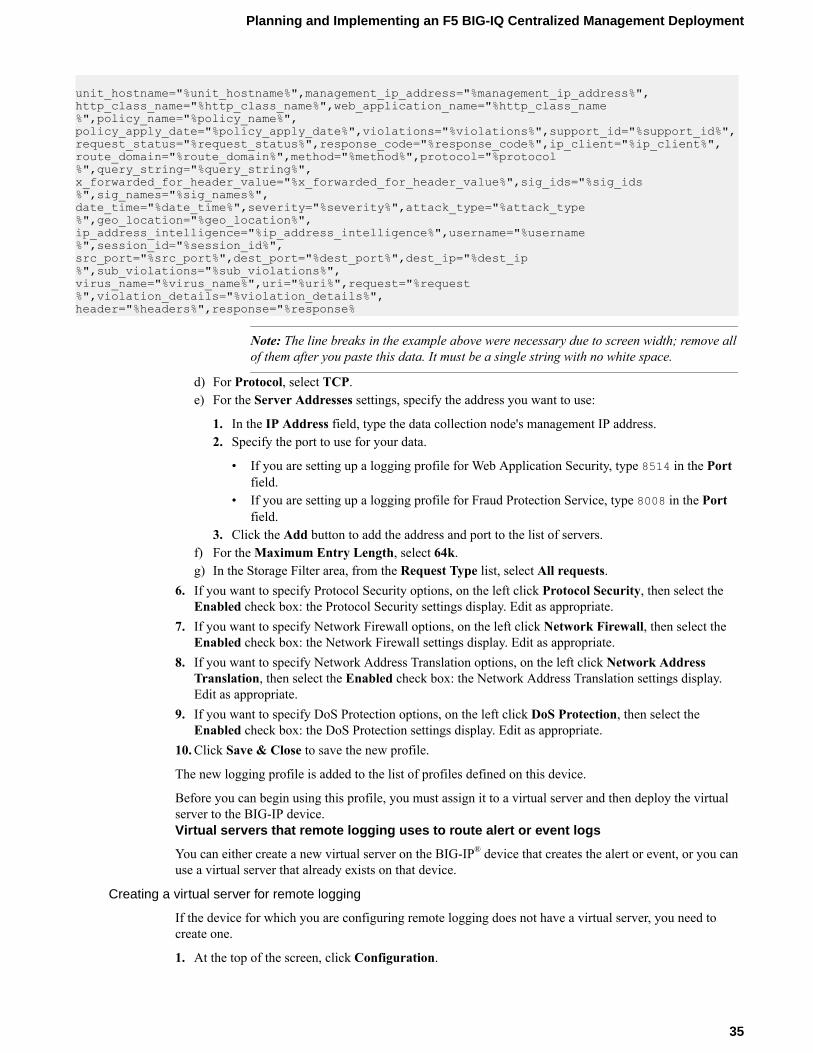
unit_hostname="%unit_hostname%",management_ip_address="%management_ip_address%",http_class_name="%http_class_name%",web_application_name="%http_class_name%",policy_name="%policy_name%",policy_apply_date="%policy_apply_date%",violations="%violations%",support_id="%support_id%",request_status="%request_status%",response_code="%response_code%",ip_client="%ip_client%",route_domain="%route_domain%",method="%method%",protocol="%protocol%",query_string="%query_string%",x_forwarded_for_header_value="%x_forwarded_for_header_value%",sig_ids="%sig_ids%",sig_names="%sig_names%",date_time="%date_time%",severity="%severity%",attack_type="%attack_type%",geo_location="%geo_location%",ip_address_intelligence="%ip_address_intelligence%",username="%username%",session_id="%session_id%",src_port="%src_port%",dest_port="%dest_port%",dest_ip="%dest_ip%",sub_violations="%sub_violations%",virus_name="%virus_name%",uri="%uri%",request="%request%",violation_details="%violation_details%",header="%headers%",response="%response%
Note: The line breaks in the example above were necessary due to screen width; remove allof them after you paste this data. It must be a single string with no white space.
d) For Protocol, select TCP.e) For the Server Addresses settings, specify the address you want to use:
1. In the IP Address field, type the data collection node's management IP address.2. Specify the port to use for your data.
• If you are setting up a logging profile for Web Application Security, type 8514 in the Portfield.
• If you are setting up a logging profile for Fraud Protection Service, type 8008 in the Portfield.
3. Click the Add button to add the address and port to the list of servers.f) For the Maximum Entry Length, select 64k.g) In the Storage Filter area, from the Request Type list, select All requests.
6. If you want to specify Protocol Security options, on the left click Protocol Security, then select theEnabled check box: the Protocol Security settings display. Edit as appropriate.
7. If you want to specify Network Firewall options, on the left click Network Firewall, then select theEnabled check box: the Network Firewall settings display. Edit as appropriate.
8. If you want to specify Network Address Translation options, on the left click Network AddressTranslation, then select the Enabled check box: the Network Address Translation settings display.Edit as appropriate.
9. If you want to specify DoS Protection options, on the left click DoS Protection, then select theEnabled check box: the DoS Protection settings display. Edit as appropriate.
10. Click Save & Close to save the new profile.
The new logging profile is added to the list of profiles defined on this device.
Before you can begin using this profile, you must assign it to a virtual server and then deploy the virtualserver to the BIG-IP device.Virtual servers that remote logging uses to route alert or event logs
You can either create a new virtual server on the BIG-IP® device that creates the alert or event, or you canuse a virtual server that already exists on that device.
Creating a virtual server for remote logging
If the device for which you are configuring remote logging does not have a virtual server, you need tocreate one.
1. At the top of the screen, click Configuration.
Planning and Implementing an F5 BIG-IQ Centralized Management Deployment
35
2. On the left, expand LOCAL TRAFFIC.3. Under LOCAL TRAFFIC, select Virtual Servers.
The screen displays a list of virtual servers defined on this device.4. Click Create.
The Virtual Servers - New Item screen opens.5. In the Name field, type in a name for the virtual server you are creating.6. From the Device list, select the device on which to create the virtual server.7. In the Description field, type in a brief description for the virtual server you are creating.8. For the Destination Address, type the IP address of the destination you want to add to the
Destination list.
The format for an IPv4 address is I<a>.I<b>.I<c>.I<d>. For example, 172.16.254.1.
The format for an IPv6 address is I<a>:I<b>:I<c>:I<d>:I<e>:I<f>:I<g>:I<h>..For example, 2001:db8:85a3:8d3:1319:8a2e:370:7348.
9. In the Service Port field, type a service port number, or select a type from the list.When you select a type from the list, the value in the Service Port field changes to reflect theassociated default, which you can change.
10. Click Save.The system creates the new virtual server with the settings you specified.
11. Click Save to save the assignment. Or, click Save & Close to save the assignment and return to theVirtual Servers screen.
A virtual server that can be used to route alert or event data to the logging node is created for the BIG-IP®
device.
Before the BIG-IP device can actually use this new virtual server, you must deploy it to the device.Assign the logging profile to a virtual server
After configuring a logging profile on the BIG-IQ® system, you must assign it to a virtual server anddeploy it to the BIG-IP® device from which you want to collect event logs.
1. At the top of the screen, click Configuration.2. On the left, click SECURITY > Shared Security > Virtual Servers.
The screen displays a list of virtual servers that are configured with devices that have beenprovisioned and discovered.
3. On the Virtual Servers screen, click the name of the virtual server you want to use.The Virtual Servers - Properties screen opens.
4. From the Log Profiles list, under Available, click a logging profile and move it to the Selected list.5. Click Save & Close to save the assignment and return to the Virtual Servers screen.
The virtual server is now associated with the logging profile.
Before the BIG-IP system(s) can start sending alert or event logs to the data collection device, you mustdeploy the changes you just made to the BIG-IP device.
Data collection device sizing guidelines
The number of devices of each type that will best meet your company's needs depends on a number offactors. Refer to the F5 BIG-IQ Centralized Management: Data Collection Device Sizing Guide onsupport.f5.com for details.
Planning and Implementing a Centralized Management Deployment
36
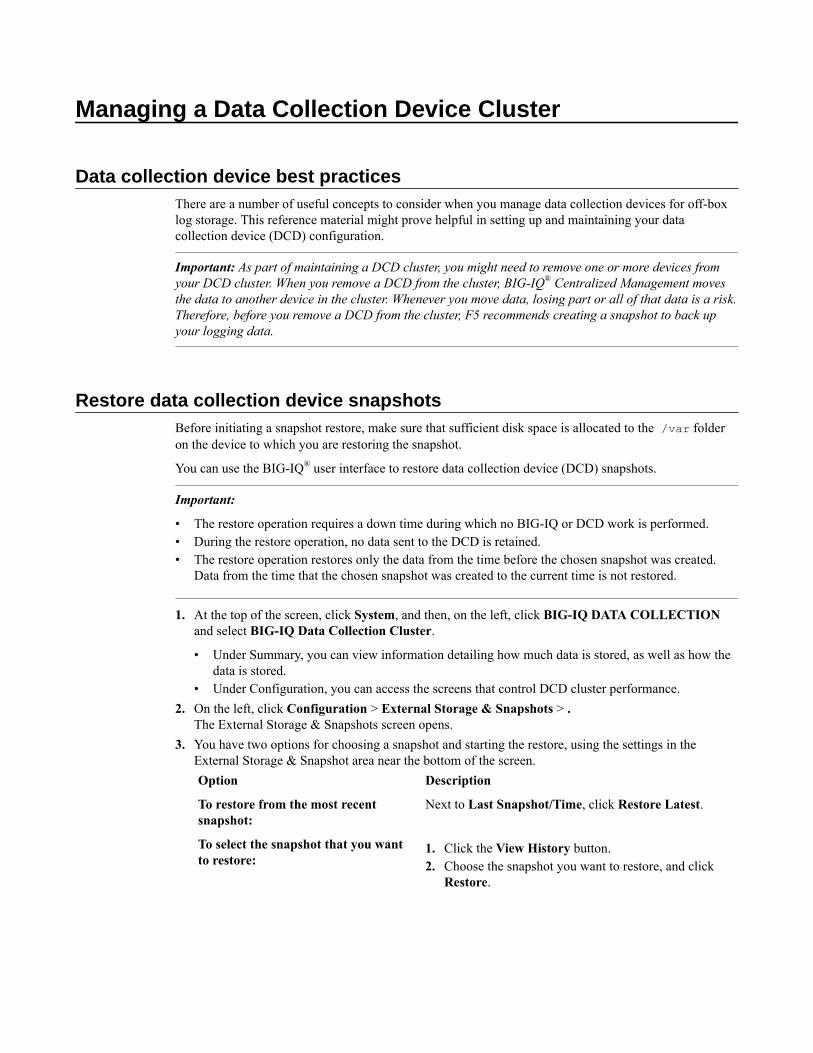
Managing a Data Collection Device Cluster
Data collection device best practicesThere are a number of useful concepts to consider when you manage data collection devices for off-boxlog storage. This reference material might prove helpful in setting up and maintaining your datacollection device (DCD) configuration.
Important: As part of maintaining a DCD cluster, you might need to remove one or more devices fromyour DCD cluster. When you remove a DCD from the cluster, BIG-IQ® Centralized Management movesthe data to another device in the cluster. Whenever you move data, losing part or all of that data is a risk.Therefore, before you remove a DCD from the cluster, F5 recommends creating a snapshot to back upyour logging data.
Restore data collection device snapshotsBefore initiating a snapshot restore, make sure that sufficient disk space is allocated to the /var folderon the device to which you are restoring the snapshot.
You can use the BIG-IQ® user interface to restore data collection device (DCD) snapshots.
Important:
• The restore operation requires a down time during which no BIG-IQ or DCD work is performed.• During the restore operation, no data sent to the DCD is retained.• The restore operation restores only the data from the time before the chosen snapshot was created.
Data from the time that the chosen snapshot was created to the current time is not restored.
1. At the top of the screen, click System, and then, on the left, click BIG-IQ DATA COLLECTIONand select BIG-IQ Data Collection Cluster.
• Under Summary, you can view information detailing how much data is stored, as well as how thedata is stored.
• Under Configuration, you can access the screens that control DCD cluster performance.2. On the left, click Configuration > External Storage & Snapshots > .
The External Storage & Snapshots screen opens.3. You have two options for choosing a snapshot and starting the restore, using the settings in the
External Storage & Snapshot area near the bottom of the screen.Option Description
To restore from the most recentsnapshot:
Next to Last Snapshot/Time, click Restore Latest.
To select the snapshot that you wantto restore:
1. Click the View History button.2. Choose the snapshot you want to restore, and click
Restore.
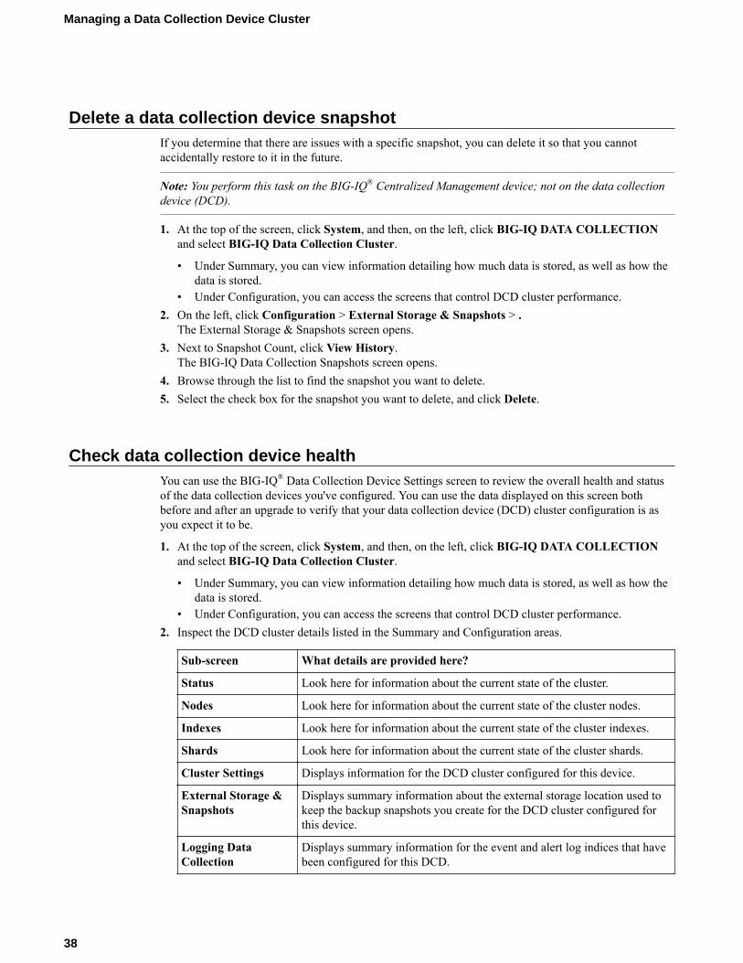
Delete a data collection device snapshotIf you determine that there are issues with a specific snapshot, you can delete it so that you cannotaccidentally restore to it in the future.
Note: You perform this task on the BIG-IQ® Centralized Management device; not on the data collectiondevice (DCD).
1. At the top of the screen, click System, and then, on the left, click BIG-IQ DATA COLLECTIONand select BIG-IQ Data Collection Cluster.
• Under Summary, you can view information detailing how much data is stored, as well as how thedata is stored.
• Under Configuration, you can access the screens that control DCD cluster performance.2. On the left, click Configuration > External Storage & Snapshots > .
The External Storage & Snapshots screen opens.3. Next to Snapshot Count, click View History.
The BIG-IQ Data Collection Snapshots screen opens.4. Browse through the list to find the snapshot you want to delete.5. Select the check box for the snapshot you want to delete, and click Delete.
Check data collection device healthYou can use the BIG-IQ® Data Collection Device Settings screen to review the overall health and statusof the data collection devices you've configured. You can use the data displayed on this screen bothbefore and after an upgrade to verify that your data collection device (DCD) cluster configuration is asyou expect it to be.
1. At the top of the screen, click System, and then, on the left, click BIG-IQ DATA COLLECTIONand select BIG-IQ Data Collection Cluster.
• Under Summary, you can view information detailing how much data is stored, as well as how thedata is stored.
• Under Configuration, you can access the screens that control DCD cluster performance.2. Inspect the DCD cluster details listed in the Summary and Configuration areas.
Sub-screen What details are provided here?
Status Look here for information about the current state of the cluster.
Nodes Look here for information about the current state of the cluster nodes.
Indexes Look here for information about the current state of the cluster indexes.
Shards Look here for information about the current state of the cluster shards.
Cluster Settings Displays information for the DCD cluster configured for this device.
External Storage &Snapshots
Displays summary information about the external storage location used tokeep the backup snapshots you create for the DCD cluster configured forthis device.
Logging DataCollection
Displays summary information for the event and alert log indices that havebeen configured for this DCD.
Managing a Data Collection Device Cluster
38
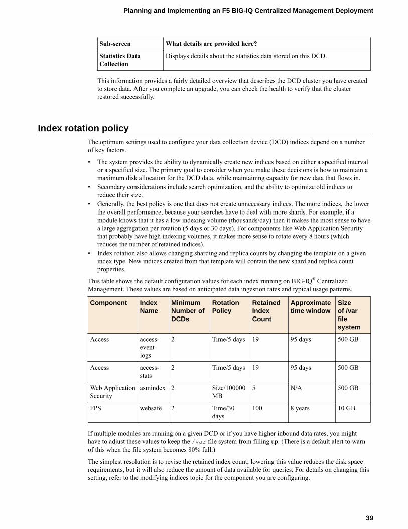
Sub-screen What details are provided here?
Statistics DataCollection
Displays details about the statistics data stored on this DCD.
This information provides a fairly detailed overview that describes the DCD cluster you have createdto store data. After you complete an upgrade, you can check the health to verify that the clusterrestored successfully.
Index rotation policyThe optimum settings used to configure your data collection device (DCD) indices depend on a numberof key factors.
• The system provides the ability to dynamically create new indices based on either a specified intervalor a specified size. The primary goal to consider when you make these decisions is how to maintain amaximum disk allocation for the DCD data, while maintaining capacity for new data that flows in.
• Secondary considerations include search optimization, and the ability to optimize old indices toreduce their size.
• Generally, the best policy is one that does not create unnecessary indices. The more indices, the lowerthe overall performance, because your searches have to deal with more shards. For example, if amodule knows that it has a low indexing volume (thousands/day) then it makes the most sense to havea large aggregation per rotation (5 days or 30 days). For components like Web Application Securitythat probably have high indexing volumes, it makes more sense to rotate every 8 hours (whichreduces the number of retained indices).
• Index rotation also allows changing sharding and replica counts by changing the template on a givenindex type. New indices created from that template will contain the new shard and replica countproperties.
This table shows the default configuration values for each index running on BIG-IQ® CentralizedManagement. These values are based on anticipated data ingestion rates and typical usage patterns.
Component IndexName
MinimumNumber ofDCDs
RotationPolicy
RetainedIndexCount
Approximatetime window
Sizeof /varfilesystem
Access access-event-logs
2 Time/5 days 19 95 days 500 GB
Access access-stats
2 Time/5 days 19 95 days 500 GB
Web ApplicationSecurity
asmindex 2 Size/100000MB
5 N/A 500 GB
FPS websafe 2 Time/30days
100 8 years 10 GB
If multiple modules are running on a given DCD or if you have higher inbound data rates, you mighthave to adjust these values to keep the /var file system from filling up. (There is a default alert to warnof this when the file system becomes 80% full.)
The simplest resolution is to revise the retained index count; lowering this value reduces the disk spacerequirements, but it will also reduce the amount of data available for queries. For details on changing thissetting, refer to the modifying indices topic for the component you are configuring.
Planning and Implementing an F5 BIG-IQ Centralized Management Deployment
39

Changing the minimum number of master eligible devicesYou can manage the minimum number of devices that must be available for the cluster to be consideredoperational. If the number of available devices is less than the value specified for the Minimum MasterEligible Devices, the cluster is deemed unhealthy.
1. At the top of the screen, click System, and then, on the left, click BIG-IQ DATA COLLECTIONand select BIG-IQ Data Collection Cluster.
• Under Summary, you can view information detailing how much data is stored, as well as how thedata is stored.
• Under Configuration, you can access the screens that control DCD cluster performance.2. On the left, click Configuration > Cluster Settings.
The Cluster Settings screen opens.3. To change this setting, click Override.
The button text changes to Update.4. In the Minimum Master Eligible Devices field, specify the new minimum number of healthy
devices for this DCD cluster, and click Update.The system updates the setting.
5. When you are satisfied with the minimum number of devices setting, click Cancel to close the screen.
Managing a Data Collection Device Cluster
40
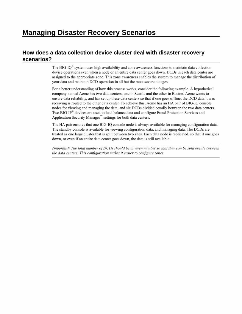
Managing Disaster Recovery Scenarios
How does a data collection device cluster deal with disaster recoveryscenarios?
The BIG-IQ® system uses high availability and zone awareness functions to maintain data collectiondevice operations even when a node or an entire data center goes down. DCDs in each data center areassigned to the appropriate zone. This zone awareness enables the system to manage the distribution ofyour data and maintain DCD operation in all but the most severe outages.
For a better understanding of how this process works, consider the following example. A hypotheticalcompany named Acme has two data centers; one in Seattle and the other in Boston. Acme wants toensure data reliability, and has set up these data centers so that if one goes offline, the DCD data it wasreceiving is routed to the other data center. To achieve this, Acme has an HA pair of BIG-IQ consolenodes for viewing and managing the data, and six DCDs divided equally between the two data centers.Two BIG-IP® devices are used to load balance data and configure Fraud Protection Services andApplication Security Manager™ settings for both data centers.
The HA pair ensures that one BIG-IQ console node is always available for managing configuration data.The standby console is available for viewing configuration data, and managing data. The DCDs aretreated as one large cluster that is split between two sites. Each data node is replicated, so that if one goesdown, or even if an entire data center goes down, the data is still available.
Important: The total number of DCDs should be an even number so that they can be split evenly betweenthe data centers. This configuration makes it easier to configure zones.
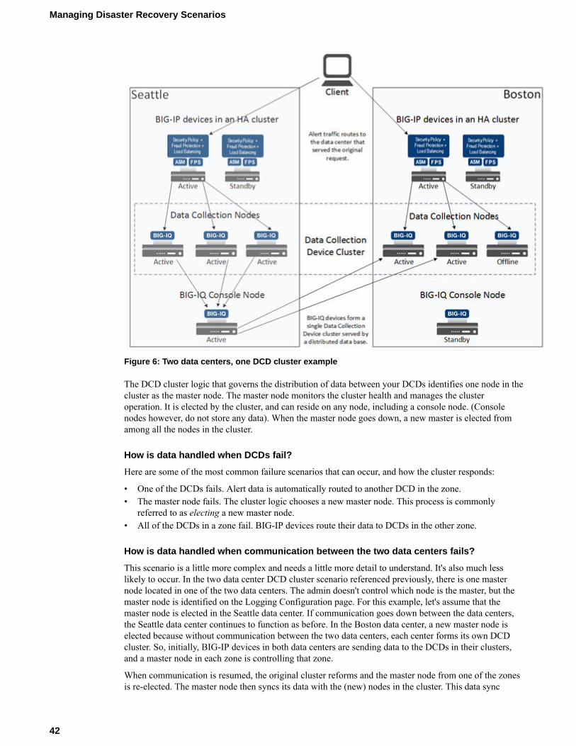
Figure 6: Two data centers, one DCD cluster example
The DCD cluster logic that governs the distribution of data between your DCDs identifies one node in thecluster as the master node. The master node monitors the cluster health and manages the clusteroperation. It is elected by the cluster, and can reside on any node, including a console node. (Consolenodes however, do not store any data). When the master node goes down, a new master is elected fromamong all the nodes in the cluster.
How is data handled when DCDs fail?
Here are some of the most common failure scenarios that can occur, and how the cluster responds:
• One of the DCDs fails. Alert data is automatically routed to another DCD in the zone.• The master node fails. The cluster logic chooses a new master node. This process is commonly
referred to as electing a new master node.• All of the DCDs in a zone fail. BIG-IP devices route their data to DCDs in the other zone.
How is data handled when communication between the two data centers fails?
This scenario is a little more complex and needs a little more detail to understand. It's also much lesslikely to occur. In the two data center DCD cluster scenario referenced previously, there is one masternode located in one of the two data centers. The admin doesn't control which node is the master, but themaster node is identified on the Logging Configuration page. For this example, let's assume that themaster node is elected in the Seattle data center. If communication goes down between the data centers,the Seattle data center continues to function as before. In the Boston data center, a new master node iselected because without communication between the two data centers, each center forms its own DCDcluster. So, initially, BIG-IP devices in both data centers are sending data to the DCDs in their clusters,and a master node in each zone is controlling that zone.
When communication is resumed, the original cluster reforms and the master node from one of the zonesis re-elected. The master node then syncs its data with the (new) nodes in the cluster. This data sync
Managing Disaster Recovery Scenarios
42
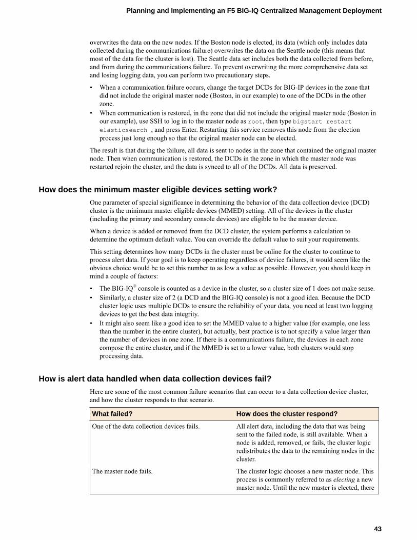
overwrites the data on the new nodes. If the Boston node is elected, its data (which only includes datacollected during the communications failure) overwrites the data on the Seattle node (this means thatmost of the data for the cluster is lost). The Seattle data set includes both the data collected from before,and from during the communications failure. To prevent overwriting the more comprehensive data setand losing logging data, you can perform two precautionary steps.
• When a communication failure occurs, change the target DCDs for BIG-IP devices in the zone thatdid not include the original master node (Boston, in our example) to one of the DCDs in the otherzone.
• When communication is restored, in the zone that did not include the original master node (Boston inour example), use SSH to log in to the master node as root, then type bigstart restartelasticsearch , and press Enter. Restarting this service removes this node from the electionprocess just long enough so that the original master node can be elected.
The result is that during the failure, all data is sent to nodes in the zone that contained the original masternode. Then when communication is restored, the DCDs in the zone in which the master node wasrestarted rejoin the cluster, and the data is synced to all of the DCDs. All data is preserved.
How does the minimum master eligible devices setting work?
One parameter of special significance in determining the behavior of the data collection device (DCD)cluster is the minimum master eligible devices (MMED) setting. All of the devices in the cluster(including the primary and secondary console devices) are eligible to be the master device.
When a device is added or removed from the DCD cluster, the system performs a calculation todetermine the optimum default value. You can override the default value to suit your requirements.
This setting determines how many DCDs in the cluster must be online for the cluster to continue toprocess alert data. If your goal is to keep operating regardless of device failures, it would seem like theobvious choice would be to set this number to as low a value as possible. However, you should keep inmind a couple of factors:
• The BIG-IQ® console is counted as a device in the cluster, so a cluster size of 1 does not make sense.• Similarly, a cluster size of 2 (a DCD and the BIG-IQ console) is not a good idea. Because the DCD
cluster logic uses multiple DCDs to ensure the reliability of your data, you need at least two loggingdevices to get the best data integrity.
• It might also seem like a good idea to set the MMED value to a higher value (for example, one lessthan the number in the entire cluster), but actually, best practice is to not specify a value larger thanthe number of devices in one zone. If there is a communications failure, the devices in each zonecompose the entire cluster, and if the MMED is set to a lower value, both clusters would stopprocessing data.
How is alert data handled when data collection devices fail?
Here are some of the most common failure scenarios that can occur to a data collection device cluster,and how the cluster responds to that scenario.
What failed? How does the cluster respond?
One of the data collection devices fails. All alert data, including the data that was beingsent to the failed node, is still available. When anode is added, removed, or fails, the cluster logicredistributes the data to the remaining nodes in thecluster.
The master node fails. The cluster logic chooses a new master node. Thisprocess is commonly referred to as electing a newmaster node. Until the new master is elected, there
Planning and Implementing an F5 BIG-IQ Centralized Management Deployment
43
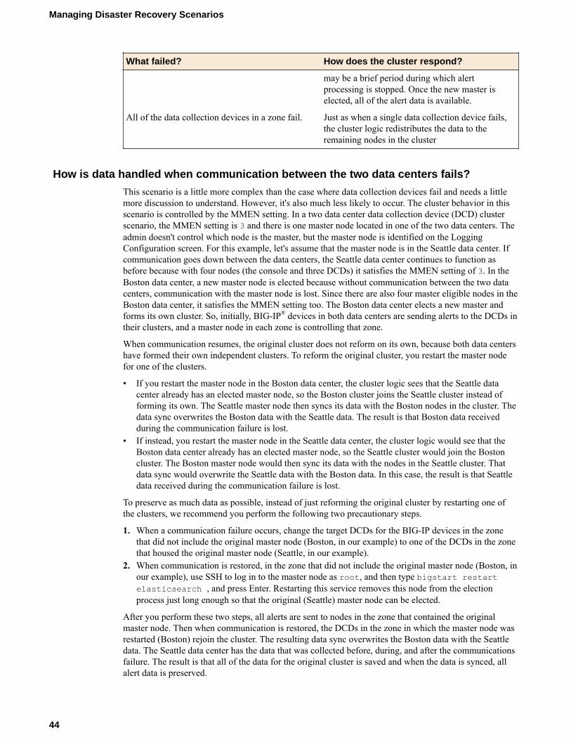
What failed? How does the cluster respond?
may be a brief period during which alertprocessing is stopped. Once the new master iselected, all of the alert data is available.
All of the data collection devices in a zone fail. Just as when a single data collection device fails,the cluster logic redistributes the data to theremaining nodes in the cluster
How is data handled when communication between the two data centers fails?
This scenario is a little more complex than the case where data collection devices fail and needs a littlemore discussion to understand. However, it's also much less likely to occur. The cluster behavior in thisscenario is controlled by the MMEN setting. In a two data center data collection device (DCD) clusterscenario, the MMEN setting is 3 and there is one master node located in one of the two data centers. Theadmin doesn't control which node is the master, but the master node is identified on the LoggingConfiguration screen. For this example, let's assume that the master node is in the Seattle data center. Ifcommunication goes down between the data centers, the Seattle data center continues to function asbefore because with four nodes (the console and three DCDs) it satisfies the MMEN setting of 3. In theBoston data center, a new master node is elected because without communication between the two datacenters, communication with the master node is lost. Since there are also four master eligible nodes in theBoston data center, it satisfies the MMEN setting too. The Boston data center elects a new master andforms its own cluster. So, initially, BIG-IP® devices in both data centers are sending alerts to the DCDs intheir clusters, and a master node in each zone is controlling that zone.
When communication resumes, the original cluster does not reform on its own, because both data centershave formed their own independent clusters. To reform the original cluster, you restart the master nodefor one of the clusters.
• If you restart the master node in the Boston data center, the cluster logic sees that the Seattle datacenter already has an elected master node, so the Boston cluster joins the Seattle cluster instead offorming its own. The Seattle master node then syncs its data with the Boston nodes in the cluster. Thedata sync overwrites the Boston data with the Seattle data. The result is that Boston data receivedduring the communication failure is lost.
• If instead, you restart the master node in the Seattle data center, the cluster logic would see that theBoston data center already has an elected master node, so the Seattle cluster would join the Bostoncluster. The Boston master node would then sync its data with the nodes in the Seattle cluster. Thatdata sync would overwrite the Seattle data with the Boston data. In this case, the result is that Seattledata received during the communication failure is lost.
To preserve as much data as possible, instead of just reforming the original cluster by restarting one ofthe clusters, we recommend you perform the following two precautionary steps.
1. When a communication failure occurs, change the target DCDs for the BIG-IP devices in the zonethat did not include the original master node (Boston, in our example) to one of the DCDs in the zonethat housed the original master node (Seattle, in our example).
2. When communication is restored, in the zone that did not include the original master node (Boston, inour example), use SSH to log in to the master node as root, and then type bigstart restartelasticsearch , and press Enter. Restarting this service removes this node from the electionprocess just long enough so that the original (Seattle) master node can be elected.
After you perform these two steps, all alerts are sent to nodes in the zone that contained the originalmaster node. Then when communication is restored, the DCDs in the zone in which the master node wasrestarted (Boston) rejoin the cluster. The resulting data sync overwrites the Boston data with the Seattledata. The Seattle data center has the data that was collected before, during, and after the communicationsfailure. The result is that all of the data for the original cluster is saved and when the data is synced, allalert data is preserved.
Managing Disaster Recovery Scenarios
44
How do I optimize my deployment for disaster recovery?
When you have data collection devices in multiple data centers, you can optimize your deployment tomaintain data collection when some or all of the data collection devices in one data center fail. A fewslight variations to the deployment process make it possible for you to take advantage of the BIG-IQ®
system's zone awareness feature. The resulting data collection device (DCD) cluster deployment providesthe optimum data collection performance in an outage scenario.
Note: In the user interface, a data center is identified by its zone name. The data center in Seattle and thezone named Seattle are the same thing.
1. Install and configure a BIG-IQ console node in both data centers.2. Configure the two console nodes so that one is the HA primary and the other is the HA secondary.3. For the console node configured as the HA primary, specify the zone in which that device resides.4. Deploy the DCD in each data center.5. On the primary console node, add all of the DCDs to the cluster. As you add devices, specify the zone
name appropriate for the data center in which each node is physically located.6. Initiate an HA failover of the primary BIG-IQ console to the secondary BIG-IQ console.
When the BIG-IQ HA primary fails over to the secondary, the logging configuration informationpropagates to both zones and a new primary is designated.
7. On the (newly designated) primary BIG-IQ console, specify the name of the zone in which thatconsole resides.
8. Initiate an HA failover of the (new) primary BIG-IQ console to the secondary BIG-IQ console.The BIG-IQ console that was originally the HA primary is once again the primary.
9. Set the minimum master capable devices on the primary console. To display the HA propertiesscreen, click System > BIG-IQ HA and then select the device.The Zone field is located at the bottom of the screen.
Changing the minimum number of master eligible devices
You can manage the minimum number of devices that must be available for the cluster to be consideredoperational. If the number of available devices is less than the value specified for the Minimum MasterEligible Devices, the cluster is deemed unhealthy.
1. At the top of the screen, click System, and then, on the left, click BIG-IQ DATA COLLECTIONand select BIG-IQ Data Collection Cluster.
• Under Summary, you can view information detailing how much data is stored, as well as how thedata is stored.
• Under Configuration, you can access the screens that control DCD cluster performance.2. On the left, click Configuration > Cluster Settings.
The Cluster Settings screen opens.3. To change this setting, click Override.
The button text changes to Update.4. In the Minimum Master Eligible Devices field, specify the new minimum number of healthy
devices for this DCD cluster, and click Update.The system updates the setting.
5. When you are satisfied with the minimum number of devices setting, click Cancel to close the screen.
How do I perform routine maintenance on a node?
Planning and Implementing an F5 BIG-IQ Centralized Management Deployment
45
Before you do routine maintenance on a data collection device (DCD), there are a couple of steps youshould perform to make sure the DCD cluster operation is not impacted.
1. On the BIG-IQ Data Collection Devices screen, remove the node from the DCD cluster.The system recalculates and resets the Minimum Master Eligible Nodes setting.
2. If your DCD cluster configuration does not use the default value, override the Minimum MasterEligible Nodes setting to its previous value.
3. Perform the maintenance on the DCD.4. Add the node back into the DCD cluster.
The system recalculates and resets the Minimum Master Eligible Nodes setting.5. If your DCD cluster configuration does not use the default value, override the Minimum Master
Eligible Nodes setting to its previous value.
How do I change the zone for a data collection device?
If you decide to change the zone for a data collection device (DCD), you should perform a couple ofextra steps to make sure that the cluster recognizes the change.
1. At the top of the screen, click System, and then, on the left, click BIG-IQ DATA COLLECTION >BIG-IQ Data Collection Devices.The BIG-IQ Data Collection Devices screen opens to list the data collection devices in the cluster.
2. Under Device Name, select the DCD that you want to revise.3. On the DCDs properties page, click Edit to change the zone for the DCD.4. Use SSH to log in to DCD as root.5. Type bigstart restart elasticsearch. and press Enter.6. Repeat the last two steps for each DCD, and for each BIG-IQ ®system in the cluster.
Note: As you run this command on each DCD, it momentarily stops processing DCD data, so the dataroutes to another node in the cluster and no data is lost.
Managing Disaster Recovery Scenarios
46
Legal Notices
Legal notices
Publication Date
This document was published on February 12, 2018.
Publication Number
MAN-0666-02
Copyright
Copyright © 2018, F5 Networks, Inc. All rights reserved.
F5 Networks, Inc. (F5) believes the information it furnishes to be accurate and reliable. However, F5assumes no responsibility for the use of this information, nor any infringement of patents or other rightsof third parties which may result from its use. No license is granted by implication or otherwise underany patent, copyright, or other intellectual property right of F5 except as specifically described byapplicable user licenses. F5 reserves the right to change specifications at any time without notice.
Trademarks
For a current list of F5 trademarks and service marks, see http://www.f5.com/about/guidelines-policies/trademarks.
All other product and company names herein may be trademarks of their respective owners.
Patents
This product may be protected by one or more patents indicated at: https://f5.com/about-us/policies/patents.
Export Regulation Notice
This product may include cryptographic software. Under the Export Administration Act, the UnitedStates government may consider it a criminal offense to export this product from the United States.
RF Interference Warning
This is a Class A product. In a domestic environment this product may cause radio interference, in whichcase the user may be required to take adequate measures.
FCC Compliance
This equipment has been tested and found to comply with the limits for a Class A digital device pursuantto Part 15 of FCC rules. These limits are designed to provide reasonable protection against harmfulinterference when the equipment is operated in a commercial environment. This unit generates, uses, andcan radiate radio frequency energy and, if not installed and used in accordance with the instructionmanual, may cause harmful interference to radio communications. Operation of this equipment in aresidential area is likely to cause harmful interference, in which case the user, at his own expense, will berequired to take whatever measures may be required to correct the interference.

Any modifications to this device, unless expressly approved by the manufacturer, can void the user'sauthority to operate this equipment under part 15 of the FCC rules.
Canadian Regulatory Compliance
This Class A digital apparatus complies with Canadian ICES-003.
Standards Compliance
This product conforms to the IEC, European Union, ANSI/UL and Canadian CSA standards applicable toInformation Technology products at the time of manufacture.
Legal Notices
48

Index
A
alert dataand handling logging failure 43when data collection devices fail 43
alert log indicesconfiguring 25defined 25modifying 25
alert or event log indicesdefined 26, 27
alert or event logsconfiguring snapshot schedules 32
B
base registration keyabout 17, 21
best practicesData Collection Device cluster 37
BIG-IP logging profilechecking configuration 38configuring 33, 34
BIG-IQ data collection deviceabout setup 33
BIG-IQ deploymentabout 14
BIG-IQ systemabout licensing and initial setup 15about licensing and initial setup for data collectiondevice 19
C
capacity planningfor data collection device 36
centralized management deploymentplanning for 7prerequisites 7
centralized management solutionsdefined 6
cluster configurationchecking for data collection device 38
communication failuresdata handling 44
configurationand initial setup 15, 17, 20, 21
D
data collection deviceabout BIG-IQ setup 33about capacity planning 36activating 23adding to a Logging Group 23changing zone 46configuring snapshot schedules 32
data collection device (continued)defined 36discovering 23extending file size 36recommended configuration 36restoring snapshots 37securing communications 30
data collection device clusterand disaster recovery 41
data collection device deploymentabout 19
data collection device failureand handling alert data 43
data collection device snapshotsdeleting 38restoring 37
data collection devicesdoing routine maintenance 45
data handlingwhen communications fail 44
DCD zonechanging 46
default passwordsfor admin and root 14
deploymentplanning for 7
deployment options 8deployment overview
data collection device cluster 19deployment resource requirements 12devices
managing number of master eligible 40, 45disaster recovery
optimizing deployment for 45overview 41
discovery addressdefined 15, 20
dossierproviding 15, 17, 20, 21
E
Elasticsearchand data collection device 36
eligible devicesmanaging number of master 40, 45
event log indicesconfiguring 26, 27
event logsconfiguring the logging profile 25, 33, 34
event or alert log snapshotsrestoring 37
event or alert logsrestoring snapshots 37
events and alertsrouting to DCD 33
Index
49

H
HTTPSconfiguring for data collection device 30
I
index rotationfor log indices 24
index rotation policyabout 39default configuration values 39
initial configurationfor BIG-IQ system 15, 17, 20, 21
L
licenseactivating automatically 15, 20activating manually 17, 21
license activationfor a data collection device 20for BIG-IQ system 15, 17, 21
licensesrequired for DCD cluster install 14
licensingperforming automatically for a data collection device 20performing automatically for BIG-IQ system 15
log indicesabout 24
logging profileassigning to a virtual server 35, 36checking data collection device 38checking health 38configuring 25–27, 33, 34sending alerts or events to Logging Node 26, 27sending events to data collection device 25, 33, 34sending events to Logging Node 25
logsrestoring snapshots 37
M
maintenancefor data collection device 45performing routine 45
master eligible devicesmanaging minimum number of 40, 45
minimum master eligible devices 43minimum number of master eligible devices
managing 40, 45
N
network configurationand deployment options 8
network environmentand setup 9, 10preparing for BIG-IQ deployment 7
nodesdoing routine maintenance 45
O
open portsrequired for deployment 13
P
passwordsrequired for DCD install 14
ports, openrequired for deployment 13
proxiesconfiguring 30
R
recoveryfrom disaster, overview 41planning for disaster 45
remote loggingvirtual servers 35
required resources 12retention policy
managing 28routine maintenance
for data collection device 45
S
secure communicationadding a proxy 30
setupfor a data collection device 20for BIG-IQ 15for BIG-IQ data collection device 19for BIG-IQ system 15, 17, 21for network environment 9, 10
snapshot locationsdefining 31
snapshot schedulesdefining 32
snapshot storagedefining locations 31
snapshotsdefining schedules 32deleting for data collection device 38restoring event or alert log 37
statisticsmanaging data retention policy 28
statistics datamanaging retention policy 28
statistics retentionmanaging policy 28
system licenseabout 15, 19
V
virtual serveradding for logging profile assignment 36creating for logging profile 35
Index
50

virtual serversfor remote logging 35
Z
zonechanging 46changing for data collection device 46
Index
51

Index
52