Embed Size (px)
Citation preview

C H A P T E R 2
Planning and Packaging Your Remediation ModulePlanning the development of a custom remediation module consists of the tasks listed in the following table, which indicates where to find information and guidance on each task area.
Data Available from the Remediation SubsystemCustom remediation modules can receive two kinds of data from the remediation subsystem:
event data, which includes a variety of data about the correlation policy that was violated and about the original triggering event that caused the policy violation
instance configuration data, which includes values entered in the web interface when an instance of a remediation is configured
These two types of data incorporate both the data about the network traffic or change that triggered the rules in the violated policy, and the configured instance of the remediation that runs in response to that policy violation. See “Configuring Correlation Policies and Rules” and “Configuring Responses for Correlation Policies” in the FireSIGHT System User Guide for more information about creating, configuring and using correlation policies and remediations.
See the following sections for more information:
Event Data, page 2-2 describes how event data is provided to your remediation module and lists the correlation event data available to your module.
Instance Configuration Data, page 2-8 explains how instance.config files are made available to your remediation module and describes the types of data they may include.
Table 2-1 Remediation Module Planning Tasks
For guidance on ... Look in...
performing a functional analysis and the importance of understanding the remediation subsystem concept of operations
Overview of the Development and Installation Process, page 4-2
reviewing the data available from the remediation subsystem
Data Available from the Remediation Subsystem, page 2-1
using the return code function of the remediation subsystem
Data Returned by Modules, page 2-12
coordinating your software development and generating the module.template file
Communicating with the Remediation Subsystem, page 3-1
packaging the remediation module and installing it
Packaging and Installing Your Module, page 2-12
2-1FireSIGHT System Remediation API Guide

Chapter Planning and Packaging Your Remediation ModuleData Available from the Remediation Subsystem
Event DataEvent data is one type of information available to your remediation module. Event is information about intrusion, correlation, and other event types that the Defense Center generates when rules in a correlation policy trigger. You specify the event data fields to be sent for each remediation type in your module using the pe_item element in the module.template file.
When the remediation daemon sends event data to your remediation module, it passes the name of the remediation first, followed by the pe_item fields in the order in which they appear in module.template.
The remediation daemon handles any undefined pe_item fields from the database differently depending on whether they field is marked as optional or required in module.template. See Handling Undefined Data Elements, page 4-6.
For details on specifying event data for remediations, see Defining Remediation Types, page 3-20. When specifying the pe_item element, you must use the field names provided in the tables below.
The following table describes data available about the original event that triggered the correlation policy violation. Note that some fields in this table are event specific. These fields are set to zero when not applicable for the specific type of triggering event.
Table 2 Triggering Event Data
Name Description Field Type Bytes
Transport Protocol The transport protocol (TCP, UDP, IP, ICMP) of the packet that triggered the intrusion or discovery event that caused the policy violation.
ip_protocol uint8_t 1
Network Protocol The network protocol (for example, ethernet) of the packet that triggered the intrusion or discovery event that caused the policy violation.
net_protocol uint16_t 2
Triggering Event Type
A numeric identifier for the type of event that triggered the correlation event. Values are:
1 = intrusion2 = network discovery, connection, or connection summary3 = user awareness4 = white list
event_type uint8_t 1
Triggering Event ID
An internal identifier for the event that triggered the correlation event. Set only for intrusion events. Set to 0 for other event types.
event_id uint32_t 4
Triggering Event Time
Content varies by event type:
for intrusion, network discovery, connection, and user awareness events: UNIX timestamp of the triggering event
for connection summaries: correlation event time (that is, policy_tv_sec)
for white list events: set to 0
tv_sec uint32_t 4
Triggering Event Time (usec)
The microsecond increment of the event time. Set to 0 if granularity is not available.
tv_usec uint32_t 4
Triggering Event Description
A text description of the original event that triggered the correlation event. Content varies by event type.
description char * Max 1024
2-2FireSIGHT System Remediation API Guide

Chapter Planning and Packaging Your Remediation ModuleData Available from the Remediation Subsystem
Triggering Event Sensor ID
The internal identifier of the sensor where the triggering event occurred.
Primarily for Cisco internal use, not typically used for remediations.
sensor_id uint32_t 4
Triggering Event Generator ID
Content varies by event type:
for intrusion events: the generator ID (GID) for the event. See the FireSIGHT System User Guide for a complete list of GIDs.
for network discovery and connection events: the network discovery event type.
for connection summaries: set to 4 for all.
for user awareness events: the user awareness event type.
for white list events: set to 0.
Primarily for Cisco internal use and not typically used for remediations.
sig_gen uint32_t 4
Table 2 Triggering Event Data (continued)
Name Description Field Type Bytes
2-3FireSIGHT System Remediation API Guide
Chapter Planning and Packaging Your Remediation ModuleData Available from the Remediation Subsystem
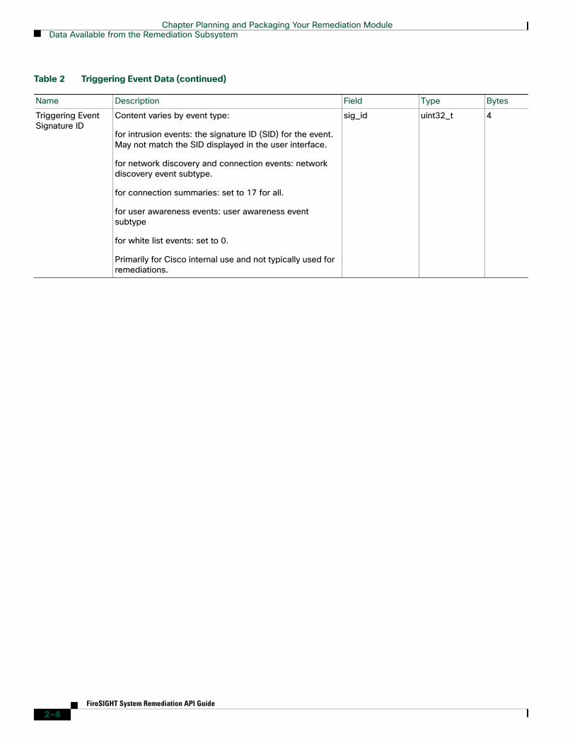
Triggering Event Signature ID
Content varies by event type:
for intrusion events: the signature ID (SID) for the event. May not match the SID displayed in the user interface.
for network discovery and connection events: network discovery event subtype.
for connection summaries: set to 17 for all.
for user awareness events: user awareness event subtype
for white list events: set to 0.
Primarily for Cisco internal use and not typically used for remediations.
sig_id uint32_t 4
Table 2 Triggering Event Data (continued)
Name Description Field Type Bytes
2-4FireSIGHT System Remediation API Guide

Chapter Planning and Packaging Your Remediation ModuleData Available from the Remediation Subsystem
The following table describes the data available about each correlation event. Note that some of the data elements are not populated for certain event types.
Impact Flags Impact flag value of the event. The low-order eight bits indicate the impact level. Values are:
0x01 (bit 0) - Source or destination host is in a network monitored by the system.
0x02 (bit 1) - Source or destination host exists in the network map.
0x04 (bit 2) - Source or destination host is running a server on the port in the event (if TCP or UDP) or uses the IP protocol.
0x08 (bit 3) - There is a vulnerability mapped to the operating system of the source or destination host in the event.
0x10 (bit 4) - There is a vulnerability mapped to the server detected in the event.
0x20 (bit 5) - The event caused the managed device to drop the session (used only when the device is running in inline, switched, or routed deployment). Corresponds to blocked status in the FireSIGHT System web interface.
0x40 (bit 6) - The rule that generated this event contains rule metadata setting the impact flag to red. The source or destination host is potentially compromised by a virus, trojan, or other piece of malicious software.
0x80 (bit 7) - There is a vulnerability mapped to the client detected in the event. (version 5.0+ only)
The following impact level values map to specific priorities on the Defense Center. An X indicates the value can be 0 or 1:
gray (0, unknown): 00X00000
red (1, vulnerable): XXXX1XXX, XXX1XXXX, X1XXXXXX, 1XXXXXXX (version 5.0+ only)
orange (2, potentially vulnerable): 00X0011X
yellow (3, currently not vulnerable): 00X0001X
blue (4, unknown target): 00X00001
impact_flags uint32_t 4
Table 2 Triggering Event Data (continued)
Name Description Field Type Bytes
2-5FireSIGHT System Remediation API Guide

Chapter Planning and Packaging Your Remediation ModuleData Available from the Remediation Subsystem
The following table defines the mask values for the correlation event message fields. These values are used in the correlation event message to indicate which of the fields that follow the mask are valid.
Table 3 Correlation Event Data
Name Description Field Type Bytes
Correlation Event Time
UNIX timestamp of when the correlation event was generated.
policy_tv_sec uint32_t 4
Correlation Event ID
The internal identification number of the event generated by the sensor. Set only for intrusion events.
Primarily for Cisco internal use and not typically used for remediations.
policy_event_id uint32_t 4
Correlation Appliance ID
The internal identification number of the Defense Center that generated the correlation event.
Primarily for Cisco internal use and not typically used for remediations.
policy_sensor_id uint32_t 4
Correlation Policy ID
The internal identification number of the of the correlation policy that was violated by the triggering event.
Primarily for Cisco internal use and not typically used for remediations.
policy_id uint32_t 4
Correlation Rule ID
The internal identification number of the correlation rule that triggered the correlation event.
Primarily for Cisco internal use and not typically used for remediations.
rule_id uint32_t 4
Correlation Rule Priority
The priority assigned to the rule for the correlation policy that generated the event. The rule may have a different priority in another policy.Value: 0 - 5 (0 = no priority)
priority uint32_t 4
Event-Defined Mask
A bit field in the correlation event message that indicates which of the fields that follow the mask are valid. See Table 2-4Event Defined Values, page 2-6 for the values.
Primarily for Cisco internal use and not typically used for remediations.
defined_mask uint32_t 4
Table 2-4 Event Defined Values
Correlation Event Field Mask Value
Event Impact Flags 0x00000001
IP Protocol 0x00000002
Network Protocol 0x00000004
Source IP 0x00000008
Source Host Type 0x00000010
Source VLAN ID 0x00000020
2-6FireSIGHT System Remediation API Guide
Chapter Planning and Packaging Your Remediation ModuleData Available from the Remediation Subsystem
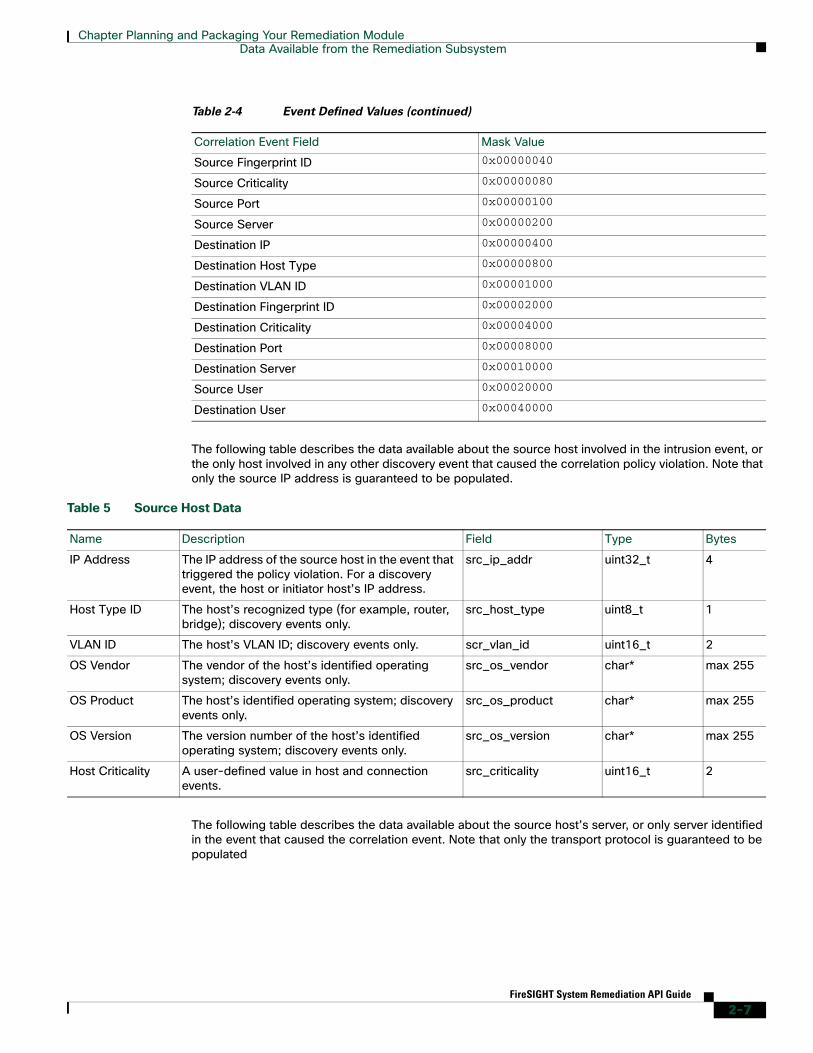
The following table describes the data available about the source host involved in the intrusion event, or the only host involved in any other discovery event that caused the correlation policy violation. Note that only the source IP address is guaranteed to be populated.
The following table describes the data available about the source host’s server, or only server identified in the event that caused the correlation event. Note that only the transport protocol is guaranteed to be populated
Source Fingerprint ID 0x00000040
Source Criticality 0x00000080
Source Port 0x00000100
Source Server 0x00000200
Destination IP 0x00000400
Destination Host Type 0x00000800
Destination VLAN ID 0x00001000
Destination Fingerprint ID 0x00002000
Destination Criticality 0x00004000
Destination Port 0x00008000
Destination Server 0x00010000
Source User 0x00020000
Destination User 0x00040000
Table 2-4 Event Defined Values (continued)
Correlation Event Field Mask Value
Table 5 Source Host Data
Name Description Field Type Bytes
IP Address The IP address of the source host in the event that triggered the policy violation. For a discovery event, the host or initiator host’s IP address.
src_ip_addr uint32_t 4
Host Type ID The host’s recognized type (for example, router, bridge); discovery events only.
src_host_type uint8_t 1
VLAN ID The host’s VLAN ID; discovery events only. scr_vlan_id uint16_t 2
OS Vendor The vendor of the host’s identified operating system; discovery events only.
src_os_vendor char* max 255
OS Product The host’s identified operating system; discovery events only.
src_os_product char* max 255
OS Version The version number of the host’s identified operating system; discovery events only.
src_os_version char* max 255
Host Criticality A user-defined value in host and connection events.
src_criticality uint16_t 2
2-7FireSIGHT System Remediation API Guide

Chapter Planning and Packaging Your Remediation ModuleData Available from the Remediation Subsystem
The following table describes the data available about the destination host. This data is only available for intrusion events.
The following table describes the data available about the destination host’s server, or the only server identified in the event that caused the correlation event. Note that only the transport protocol is guaranteed to be populated.
Instance Configuration Data When a user configures a new instance of your module, they provide data requested in your module.template document. The values provided by the user are then written into the instance.conf document for use by your remediation program.
For each configured instance of a remediation, the remediation subsystem places an instance.conf document in a directory with the same name as the instance. This directory is created in the directory where your module was uploaded and installed. For example, if your module is called Firewall, it is
Table 6 Source Server Data
Name Description Field Type Bytes
Port Port on which the identified server is running. For intrusion events, port is populated only if the protocol is TCP or UDP.
src_port uint16_t 2
Server Server (for example, HTTP, SMTP) identified in the event that caused the policy violation.
src_service char max 255
Table 7 Destination Host Data
Name Description Field Type Bytes
IP Address The IP address of the destination host in the event that triggered the policy violation.
dest_ip_addr uint32_t 4
Host Type ID The destination host’s recognized type (for example, router, bridge).
dest_host_type uint8_t 1
VLAN ID The destination host’s VLAN ID. dest_vlan_id uint16_t 2
OS Vendor The vendor of the host’s identified operating system; discovery events only.
dest_os_vendor char* max 255
OS Product The host’s identified operating system; discovery events only.
dest_os_product char* max 255
OS Version The version number of the host’s identified operating system; discovery events only.
dest_os_version char* max 255
Host Criticality A user-defined value in; discovery host and connection events.
dest_criticality uint16_t 2
Table 8 Destination Server Data
Name Description Field Type Bytes
Destination Port Port on which the identified server is running. In the case of intrusion events, the port is populated only if the protocol is identified as TCP or UDP.
dest_port uint16_t 2
Destination Server Server (for example, HTTP, SMTP) identified in the event that caused the policy violation.
dest_service char max 255
2-8FireSIGHT System Remediation API Guide
Chapter Planning and Packaging Your Remediation ModuleData Available from the Remediation Subsystem
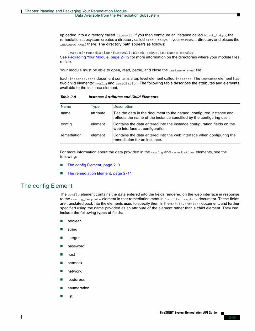
uploaded into a directory called firewall. If you then configure an instance called block_tokyo, the remediation subsystem creates a directory called block_tokyo in your firewall directory and places the instance.conf there. The directory path appears as follows:
/var/sf/remediation/firewall/block_tokyo/instance.configSee Packaging Your Module, page 2-12 for more information on the directories where your module files reside.
Your module must be able to open, read, parse, and close the instance.conf file.
Each instance.conf document contains a top level element called instance. The instance element has two child elements: config and remediation. The following table describes the attributes and elements available to the instance element.
For more information about the data provided in the config and remediation elements, see the following:
The config Element, page 2-9
The remediation Element, page 2-11
The config ElementThe config element contains the data entered into the fields rendered on the web interface in response to the config_template element in that remediation module’s module.template document. These fields are translated back into the elements used to specify them in the module.template document, and further specified using the name provided as an attribute of the element rather than a child element. They can include the following types of fields:
boolean
string
integer
password
host
netmask
network
ipaddress
enumeration
list
Table 2-9 instance Attributes and Child Elements
Name Type Description
name attribute Ties the data in the document to the named, configured instance and reflects the name of the instance specified by the configuring user.
config element Contains the data entered into the instance configuration fields on the web interface at configuration.
remediation element Contains the data entered into the web interface when configuring the remediation for an instance.
2-9FireSIGHT System Remediation API Guide

Chapter Planning and Packaging Your Remediation ModuleData Available from the Remediation Subsystem
See Defining the Configuration Template, page 3-4 for more details on how these fields are specified in the module.template file.
For example, if the module.template document contains the following config_template element definition:
<config_template><ipaddress>
<name>host_ip</name><display_name>Host IP</display_name>
</ipaddress><string>
<name>user_name</name><display_name>Username</display_name><constraints>
<pcre>\S+</pcre></constraints>
</string><password>
<name>login_password</name><display_name>Login Password</display_name>
</password></config_template>
The Instance Configuration screen for that element contains the following three fields:
Host IP, which takes an IP address value.
Username, which takes a string value that may not contain white space characters.
Login Password, which takes a string value identified as a password.
Suppose a user configures an instance, named AdminInstance, of the remediation module and provides the following values:
The instance.conf will contain the following:
<instance name=”AdminInstance”><config>
<ipaddress name=”host_ip”>192.1.1.1</ipaddress><string name=”user_name”>adminuser</string><password name=”login_password”>3admin3</password>
</config>Note that the above example does not include </instance>. This is because the instance.conf document for this example instance would go on to include the remediation element discussed next in this section. If you do not require additional remediation configuration in your module, the instance.conf returned for that module does not include remediation elements.
Table 2-10 Sample Values
Field Value
Host IP 192.1.1.1
Username adminuser
Login Password 3admin3
2-10FireSIGHT System Remediation API Guide

Chapter Planning and Packaging Your Remediation ModuleData Available from the Remediation Subsystem
The remediation ElementThe instance element contains a remediation element for each remediation configured for that instance. Each remediation element has, as an attribute, the name of the remediation instance (entered into the web interface at the time the instance is configured) and the type of the remediation, which was initially provided by the remediation_type element in the module.template document. For more information about the module.template file, see Communicating with the Remediation Subsystem, page 3-1.
In addition, remediation elements can contain config elements. These function in the same way as config elements that are child elements of instance, but use data originally specified in the config_template element that is a child of remediation_type in the module.template document. The following describes these attributes and elements.
For example, suppose the module.template document in the example provided in The config Element, page 2-9 continues with the following:
<remediation_type name="acl_insert"><display_name>ACL Insertion</display_name><policy_event_data>
<pe_item>src_ip_addr</pe_item><pe_item>src_port</pe_item><pe_item>src_protocol</pe_item><pe_item>dest_ip_addr</pe_item><pe_item>dest_port</pe_item><pe_item>dest_protocol</pe_item>
</policy_event_data><config_template>
<integer><name>acl_num</name><display_name>ACL Number</display_name>
</integer></config_template></remediation_type>
The Instance Detail page that allows you to add remediations to a created instance contains the remediation type “ACL Insertion”. Adding “ACL Insertion” to the instance takes the user to a page that includes a name field, which populates the name attribute value for that remediation element in the instance.conf, and a field labelled ACL Number, which accepts an integer value.
Suppose a user adds this remediation to the AdminInstance instance and provides the following values:
Table 2-11 remediation Attributes and Child Elements
Name Type Description
name attribute Ties the data in the document to the named, configured remediation and reflects the name specified by the configuring user.
type attribute Provides the type of remediation configured in this instance.
config element Contains the data entered into the remediation configuration fields on the web interface at configuration.
2-11FireSIGHT System Remediation API Guide

Chapter Planning and Packaging Your Remediation ModuleData Returned by Modules
The instance.conf document written when the user saved the example configuration values would, after the section provided in the example in The config Element, page 2-9, continue as follows:
<remediation name=”AdminRemediation” type=”acl_insert”><config>
<integer=”acl_num”>55</integer></config></remediation>
Note that if no more remediations were added to the instance, the instance.conf should be terminated with </instance> at this point.
Data Returned by ModulesRemediation modules must return exit status codes, known as return codes, to the Defense Center. The Table View of Remediations in the Defense Center web interface displays a result message for each remediation launched. The return code from the remediation program determines the result message displayed.
Return codes must be integers in the 0 to 255 range inclusive, as defined in the following table.
See Defining Exit Statuses, page 3-22 for the list of predefined codes and for directions on creating custom codes.
Packaging and Installing Your ModuleThe remediation API requires that you package your remediation modules. The files that make up your module must be provided in a gzipped tar file.
See the following sections for more information:
Packaging Your Module, page 2-12 provides helpful tips for packaging your binaries and module.template files for upload and installation.
Installing Your Module, page 2-13 explains how to install your remediation module on the Defense Center.
Packaging Your ModuleWhen packaging your remediation files for installation, keep in mind the following:
Table 2-12 Sample Values
Field Value
Remediation Name AdminRemediation
ACL Number 55
Table 2-13 Return Code Ranges
Range Use
0 - 128 Reserved for Cisco predefined return codes
129 - 255 Available for custom remediations
2-12FireSIGHT System Remediation API Guide

Chapter Planning and Packaging Your Remediation ModulePackaging and Installing Your Module
Remediation modules must be packaged in a gzipped tarball (.tar.gz or .tgz) before you install them.
When you install the module, the package is extracted into /var/sf/remediation/remediation_directory where remediation_directory is a combination of the name attribute of the module’s module element and the data in the version element.
For example, one of the default remediation modules shipped with the Defense Center is the Cisco PIX Shun module. That module resides in /var/sf/remediation/cisco_pix_1.0.
When extracted, your remediation module’s module.template document must reside in the top level of the directory created to contain that module package.
As instances of remediations are created, they are saved in a directory created in your module directory and named for the instance.
For example, instances of the Cisco PIX Shun module might reside in /var/sf/remediation/cisco_pix_1.0/PIX_01 and /var/sf/remediation/cisco_pix_1.0/PIX_02.
For example, you upload and install a module that is packaged in firewall.tgz and is named in the module.template as firewall with a version value of 1.0. The system installs the module in the following directory: /var/sf/remediation/firewall_1.0. That directory contains your module.template file and your program binary. When you add an instance to the remediation module and name it block_tokyo, the system creates the following directory:
/var/sf/remediation/firewall_1.0/block_tokyo and places the instance.conf file for block_tokyo in it.
Installing Your ModuleOnce you have correctly packaged your remediation module, use the Modules page to install it.
To install a new module on the Remediation API:1. Select Policies > Actions > Modules.
The Installed Remediation Modules page appears.
2. Click Browse to navigate to the location where you saved the tar.gz file that contains the custom remediation module.
3. Click Install.
The custom remediation module installs.
4. Select Policies > Actions > Modules.
The Installed Remediation Modules table lists the module just installed. The Module Name, Version, and Description columns match the information defined in the module.template file.
5. Add instances of your new module and associate remediations to each instance, as described in the FireSIGHT System User Guide.
You can use the Modules page to view the remediation modules installed on the Defense Center. The list displays custom remediation modules and Cisco-provided ones. You can also delete your custom modules.
To view or delete a module from the Remediation API:1. Select Policies > Actions > Modules.
2-13FireSIGHT System Remediation API Guide

Chapter Planning and Packaging Your Remediation ModulePackaging and Installing Your Module
The Installed Remediation Modules page appears.
2. Perform one of the following actions:
Click the View icon to view the module.
The Module Detail page appears.
Click the Delete icon next to the module you want to delete. You cannot delete default modules provided by Cisco.
The remediation module is deleted from the Remediation API.
2-14FireSIGHT System Remediation API Guide