Embed Size (px)
Citation preview
PlanWorks: A Debugging Environment forConstraint Based Planning Systems
Patrick Daley ∗ † and Jeremy Frank and Michael Iatauro ‡ and Conor McGann § and Will TaylorComputational Sciences Division
NASA Ames Research Center, MS [email protected] Field, CA 94035
IntroductionIn recent years, model-based planning has moved from rea-soning about models largely described with propositions(e.g. STRIPS) to reasoning about time, resources, and con-straints on complex numeric quantities (Smith, Frank, &Jonsson 2000), (Fox & Long 2003). Numerous planningand scheduling systems employ underlying constraint rea-soning systems to handle the richness and diversity of suchconstraints (Frank & Jonsson 2003). Debugging such sys-tems involves the search for errors in model rules, constraintreasoning algorithms, search heuristics and the problem in-stance (initial state and goals). In order to effectively findsuch problems, users must see why each state or action is ina plan by tracking causal chains back to part of the initialproblem instance. They must be able to visualize complexrelationships among many different entities and distinguishbetween those entities easily. For example, a variable can beshared between several constraints, as well as part of a stateor activity in a plan; the activity can arise as a consequenceof another activity and a model rule. Finally, they must beable to track each logical inference made during planning.
We have developedPlanWorks, a browse-based systemfor debugging constraint-based planning and schedulingsystems. PlanWorks assumes a strong transaction modelof the entire planning process, including adding and remov-ing parts of the constraint network, variable assignment, andconstraint propagation. The planner logs all transactions toa relational database that is tailored to support queries fora variety of components.Visualizationcomponents consistof specialized views to display different forms of data (e.g.constraints, activities, resources, and causal links). Eachview allows user customization in order to display only themost relevant information. Inter-view navigation features al-low users to rapidly switch views to examine the trace ofthe process from different perspectives.Transaction querymechanisms allow users access to the logged transactions tovisualize activities across the entire planning process. Whileoriginally developed for debugging, PlanWorks has the po-tential to serve as a knowledge capture tool and an end-user
∗Authors listed in alphabetical order.†Foothill College‡QSS§QSS
operations tool as well.PlanWorks is implemented in Java and employs a MySQL
relational database back-end. PlanWorks can be used eitheronline while iterative planning and debugging is performed,or offline after capturing the entire planning process. Fur-thermore, PlanWorks is an open system allowing for exten-sions to the transaction model to capture new planner al-gorithms, different classes of entity (e.g. complex resourceclasses) or novel heuristics. PlanWorks was specificallydeveloped for the Extensible Universal Remote OperationsPlanning Architecture (EUROPA2 ) developed at NASA, butthe underlying principles behind PlanWorks make it use-ful for many planning systems, a point we address at theend of the paper. PlanWorks has been used to visualizelogs generated by three different planners; two versions ofEUROPA2 as well as a prototype of the Mission Data Sys-tems (MDS) planner developed at JPL (Dvoraket al. 2000).
The paper is organized as follows. We first describesome fundamentals of the EUROPA2 constraint-based plan-ning system, and describe a simple planning domain usedthroughout the rest of the paper. We then describe Plan-Works’ principal components. We discuss each componentin detail, and then describe inter-component navigation fea-tures. We describe how to configure logging of data from theplanner to reduce debugging time, which influences whatPlanWorks can display. This configuration can be done ina configuration file, or using PlanWorks. We discuss howPlanWorks is used during debugging. Finally, we describeapplicability of PlanWorks beyond EUROPA2 , discuss sys-tem requirements and deployments, and discuss future work.
EUROPA2
EUROPA2 provides efficient, customizablePlan DatabaseServicesthat enable the integration of automated planninginto a wide variety of applications. These services are basedon some simple building blocks.Plans are composed ofpredicates, each of which has a name, start time, end time,duration, and a (possibly empty) set of parameters. Each in-stance of a predicate in a plan is represented by atoken, andeach parameter of the predicate is represented by variables.Predicates are associated with eithertimelinesthat supporttotally ordered sequences of states, orresourcesthat sup-port possibly concurrent actions that do not exceed a max-imum capacity. Timeline or resource instances are referred

to asobjects, and during planning each token is assigned toan object in the plan.Domain rulesare assertions that if apredicateP is in a plan, then other predicatesQi must alsobe in a plan, and are related toP by constraints among thevariables of the predicates. Domain rules may also assertthat resources are impacted by predicates; resource impactsare calledtransactions, and also have variables that repre-sent them. EUROPA2 does not implement any planning al-gorithm; rather, it provides services that support differentplanning algorithms according to the application. As such,it can be used to support progression planners, regressionplanners, sequential or causal link planners, and so on. Toenable this generality, EUROPA2 distinguishes betweenfreetokens (consequences of rules that haven’t been inserted intoplans),active tokensandmerged tokens. Planners can insertfree tokens into plans (making them active) or merge freetokens with active tokens.
A Sample Planning DomainEUROPA2 domains are written in a domain description lan-guage called NDDL. To illustrate the fundamentals of Plan-Works, we use a planning domain loosely based on a plan-etary surface robot namedRover. Roveris a mobile robotthat can move from location to location. ARoverhas a bat-tery on board, and can replenish its energy levels using solarpower. Locations are described as follows:
class Location {int x; int y;
Location(int x, int y) {x = x; y = y;
}}
The properties of the Rover are described as follows:
class Rover {predicate At {Location l; }predicate Going {Location from;
Location to; }Resource battery;
battery = new Battery(10, 3, 30);
}
A domain rule in EUROPA2 describing rover movementis:
Rover::Going {neq(to, from); // to != from
meets(object.At a0);
eq(a0.l, to);
met by(object.At a1);
eq(a1.l, from);
subgoal(object.battery.transaction tx);
calcConsumption(tx.quantity, from, to);
// Consume at the beginning
eq(tx.time, start);
}
Finally, a problem instance for the Rover is:
Rover spirit = new Rover();
Location rock = new Location(1, 1);
Location hill = new Location(2, 3);
Location lander = new Location(5, 8);
goal(Rover.At A);
eq(A.l, rock); eq(A.object, spirit);
leq(A.start, 0); leq(0, A.end);
goal(Rover.At B);
eq(B.l, lander); eq(B.object, spirit);
leq(B.start, 0); leq(0, B.end);
Getting PlanWorks the Goods
During planning, EUROPA2 reads the domain rules to de-termine if any of them are applicable given the current stateof the plan. If so, new tokens, resource transactions, vari-ables, and constraints are created, and the domain rule ap-plication is recorded. As the planner makes decisions, to-kens can be assigned to timelines, transactions can be as-signed to resource instances, variables can be assigned, andconstraints can be enforced, leading to reductions in the do-mains of variables. Each of these activities is logged, andeach entity is assigned a unique key that allows for the track-ing of entities and their relationships during planning. Thisinformation is passed down to PlanWorks to enable users touncover the relationships between entities in the plan.
PlanWorks can be used in one of two modes. Plannerscan generate logs for PlanWorks offline, after which Plan-Works is invoked to view the logs. When planning takes along time, this is impractical. Alternatively, PlanWorks canbe started and provided a pointer to a planner. PlanWorksthen allows the user to interleave planning and debugging.The user can run the planner for a fixed number of steps,investigate, then continue running the planner or terminateplanning.
The basic data integration point is through the database.At each “step” (where step is defined by the planner, butis logically the end of propagation after a planner decision),the current state of the plan graph, the set of transactions thatdescribe the transformation from the previous plan graph, aswell as statistics about the graph are logged in a format opti-mized for importation into the database. The set of files for asingle step are collected into a directory, which is itself in adirectory representing the particular instance of planner ex-ecution. These data are imported and queried upon request,i.e. the statistics of the plan run are loaded when the useropens the Sequence Steps View, transactions are loaded aspart of a transaction query, and the plan graph data is loadedwhen the user opens a step view.
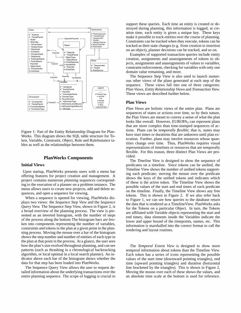
Figure 1 shows a fragment of the Entity Relationship Dia-gram for the SQL table structure describing the format Plan-Works accepts. The fragment captures the logging of themost important core components of the planning process:Tokens, Objects, Variables, Constraints, Rules and Rule In-stances. The ERD indicates key relationships between enti-ties that are logged to ensure efficient database queries; theseare later marshalled into the views that we describe in thenext section.
Legend--------------------
------# Primary Key
c varchari int
d doublee enumb blob
* required field
Token-----------------------# * TokenId# * PartialPlanIdi SlotIdi SlotIndexi * IsFreeTokeni * IsValueTokeni * StartVarIdi * EndVarIdi * DurationVarIdi * StateVarIdc PredicateNamec ParentNamei ParentIdi ObjectVarIdb ParamVarIdsb ExtraData
Object-----------------------# * ObjectId# * PartialPlanIdi ObjectTypec ObjectNameb ChildObjectIdsb VariableIdsb *TokenIdsb ExtraData
RuleInstance------------------------# *RuleInstanceId# * PartialPlanIdi * SequenceIdi * RuleIdi * MasterTokenIdb SlaveTokenIdsb RuleVarIds
Rules------------------------# * SequenceId# * RuleIdb RuleSource
Variable--------------------------# * VariableId# * PartialPlanIdi * ParentIdc * ParameterNamee *DomainTyped *EnumDomaine * IntDomainTypec IntDomainLowerBoundc IntDomainUpperBoundc * VarType
VConstraint------------------------# * ConstraintId# * PartialPlanIdc*ConstraintNamee* ConstraintType
ObjectId/ParentId
ParentId
TokenId
VariableIdsParentIdParentId
ParentId
Figure 1: Part of the Entity Relationship Diagram for Plan-Works. This diagram shows the SQL table structure for To-ken, Variable, Constraint, Object, Rule and RuleInstance ta-bles as well as the relationships between them.
PlanWorks Components
Initial Views
Upon startup, PlanWorks presents users with a menu baroffering features for project creation and management. Aproject contains numerousplanning sequencescorrespond-ing to the execution of a planner on a problem instance. Themenu allows users to create new projects, add and delete se-quences, and open a sequence for viewing.
When a sequence is opened for viewing, PlanWorks dis-plays two views: theSequence Step Viewand theSequenceQuery View.The Sequence Step View, shown in Figure 2, isa broad overview of the planning process. The view is pre-sented as an inverted histogram, with the number of stepsof the process along the bottom The histogram bars are bro-ken into components representing the number of variables,constraints and tokens in the plan at a given point in the plan-ning process. Moving the mouse over a bar of the histogramshows the step number and number of entities of each type inthe plan at that point in the process. At a glance, the user seeshow the plan’s size evolved throughout planning, and can seepatterns (such as thrashing in a chronological backtrackingalgorithm, or local optimal in a local search planner). An in-dicator above each bar of the histogram shows whether thedata for that step has been loaded into PlanWorks.
The Sequence Query View allows the user to request de-tailed information about the underlying transactions over theentire planning sequence. The scope of logging is crucial to
support these queries. Each time an entity is created or de-stroyed during planning, this information is logged; at cre-ation time, each entity is given a unique key. These keysmake it possible to track entities over the course of planning.Constraints can be tracked when they execute, tokens can betracked as their state changes (e.g. from creation to insertionon an object), planner decisions can be tracked, and so on.
Examples of supported transaction queries include entitycreation, assignments and unassignments of tokens to ob-jects, assignments and unassignments of values to variables,constraint enforcement, checking for variables with only onedomain value remaining, and more.
The Sequence Step View is also used to launch numer-ous other views of the plans generated at each step of thesequence. These views fall into one of three categories:Plan Views, Entity Relationship ViewsandTransaction View.These views are described further below.
Plan ViewsPlan Viewsare holistic views of the entire plan. Plans aresequences of states or actions over time, so by their nature,the Plan Views are meant to convey a sense of what the planlooks like overall. However, EUROPA2 can represent plansthat are more complex than time-stamped sequences of ac-tions. Plans can betemporally flexible; that is, states mayhave start times or durations that are unknown until plan ex-ecution. Further, plans may involve resources whose quan-tities change over time. Thus, PlanWorks requires visualrepresentations of timelines or resources that are temporallyflexible. For this reason, three distinct Plan Views are pro-vided.
The Timeline Viewis designed to show the sequence ofpredicates on a timeline. Since tokens can be unified, theTimeline View shows the number of unified tokens support-ing each predicate; moving the mouse over the predicateshows the keys of the unified tokens and indicates whichof these is the active token. The Timeline View shows thepossible values of the start and end times of each predicateon the timeline. Finally, the Timeline View shows any freetokens. This is shown in Figure 2. If we also refer backto Figure 1, we can see how queries to the database returnthe data that is rendered as a TimelineView. PlanWorks asksfor the Tokens on a particular Object. In turn, the Tokensare affiliated with Variable objects representing the start andend times; data elements inside the Variables indicate thelower and upper bound of the timepoints, names, etc. Thisinformation is marshalled into the correct format to call therendering and layout routines.
The Temporal Extent Viewis designed to show moretemporal information about tokens than the Timeline View.Each token has a series of icons representing the possiblevalues of the start time (downward pointing triangles), endtime (upward pointing triangles) and duration (horizontalline bracketed by the triangles). This is shown in Figure 2.Moving the mouse over each of these shows the values, andan absolute time scale at the bottom is used for reference.
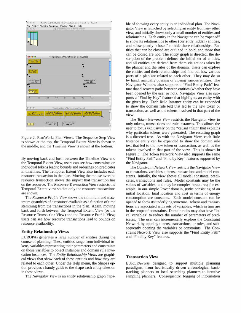
Figure 2: PlanWorks Plan Views. The Sequence Step Viewis shown at the top, the Temporal Extent View is shown inthe middle, and the Timeline View is shown at the bottom.
By moving back and forth between the Timeline View andthe Temporal Extent View, users can see how constraints onindividual tokens lead to bounds and orderings on predicatesin timelines. The Temporal Extent View also includes eachresource transaction in the plan. Moving the mouse over theresource transaction shows the impact that transaction hason the resource. TheResource Transaction Viewrestricts theTemporal Extent view so that only the resource transactionsare shown.
TheResource Profile Viewshows the minimum and max-imum quantities of a resource available as a function of timestemming from the transactions in the plan. Again, movingback and forth between the Temporal Extent View (or theResource Transaction View) and the Resource Profile View,users can see how resource transactions lead to bounds onresource availability.
Entity Relationship ViewsEUROPA2 generates a large number of entities during thecourse of planning. These entities range from individual to-kens, variables representing their parameters and constraintson those variables to object instances and domain rule invo-cation instances. TheEntity Relationship Viewsare graphi-cal views that show each of these entities and how they arerelated to each other. Under the Help menu, the Shapes op-tion provides a handy guide to the shape each entity takes onin these views.
TheNavigator Viewis an entity relationship graph capa-
ble of showing every entity in an individual plan. The Navi-gator View is launched by selecting an entity from any otherview, and initially shows only a small number of entities andrelationships. Each entity in the Navigator can be “opened”to show its relationships to other (currently hidden) entities,and subsequently “closed” to hide those relationships. En-tities that can be closed are outlined in bold, and those thatcan be closed are not. The entity graph is directed; the de-scription of the problem defines the initial set of entities,and all entities are derived from them via actions taken bythe planner and the rules of the domain. Users can explorethe entities and their relationships and find out how variousparts of a plan are related to each other. They may do soby hand, manually opening or closing various entities. TheNavigator Window also supports a “Find Entity Path” fea-ture that discovers paths between entities (whether they havebeen opened by the user or not). Navigator View also sup-ports a “Find by Key” feature that highlights an entity withthe given key. Each Rule Instance entity can be expandedto show the domain rule text that led to the new token ortransaction, as well as the tokens involved in that part of theview.
The Token Network Viewrestricts the Navigator view toonly tokens, transactions and rule instances. This allows theuser to focus exclusively on the “causal chain” that explainswhy particular tokens were generated. The resulting graphis a directed tree. As with the Navigator View, each RuleInstance entity can be expanded to show the domain ruletext that led to the new token or transaction, as well as thetokens involved in that part of the view. This is shown inFigure 3. The Token Network View also supports the same“Find Entity Path” and “Find by Key” features supported bythe Navigator.
TheConstraint Network Viewrestricts the Navigator Viewto constraints, variables, tokens, transactions and model con-stants. Initially, the view shows all model constants, predi-cates, transactions and rules. Model constants may be thevalues of variables, and may be complex structures; for ex-ample, in our simple Rover domain,pathsconsisting of aninitial location, final location and cost in terms of energyconsumption are constants. Each model constant can beopened to show its underlying structure. Tokens and transac-tions are associated with sets of variables, which in turn arein the scope of constraints. Domain rules may also have “lo-cal variables” to reduce the number of parameters of pred-icates. The user can incrementally explore the ConstraintNetwork by opening tokens, transactions, or rules, and sub-sequently opening the variables or constraints. The Con-straint Network View also supports the “Find Entity Path”and “Find by Key” features.
Transaction ViewEUROPA2 was designed to support multiple planningparadigms, from heuristically driven chronological back-tracking planners to local searching planners to iterativesampling planners. Consequently, logging of information

Figure 3: PlanWorks Token Network View and Rule In-stance forRover::Going .
about how the planner makes decisions is the responsibilityof the planner, while logging the consequences of plannerdecisions is the responsibility of EUROPA2 . The Trans-action Viewshows every transaction EUROPA2 performedthis step. This includes checking domain rule applicability,entity creation and destruction, variable assignment, tokenstate manipulation, constraint enforcement, and so on. Fig-ure 4 shows the Constraint Network View and the Transac-tion View together.
Navigating PlanWorks
An early decision was made in PlanWorks to create sep-arate Views that contain information that users typicallywant grouped. However, PlanWorks contains numerous fea-tures that allow users to efficiently navigate between Views.These features allow users of PlanWorks to rapidly movefrom View to View when debugging planning domains andplanners.
Launching Views
Almost all Views can be launched from any other View. TheNavigator View can be launched when the mouse is over anentity such as a token, variable variable, constraint, constantor rule in a View (except the Transaction View). All otherviews can be launched when the mouse is over the back-ground of a view.
Figure 4: PlanWorks Constraint Network View and Trans-action View.
Tracking Objects by Key
All objects have keys, and every view has a method to searchfor entities by key. Furthermore, the Views opened on start-ing PlanWorks have facilities for querying transactions bykey. Finally, moving the mouse over entities will show thekeys of entities. The entity relationship views can be used toprovide keys used for querying the transaction database.
Snapping to Entities
PlanWorks provides additional features to navigate betweenViews. An entity can be madeactive in one view, and theuser can then “Snap to Active Entity” in a second view.
Filtering Views
In addition to manually opening and closing entity relation-ships to incrementally explore views, PlanWorks provides acustom filter for each View. This filter allows rapid reductionof the View to exclude designated predicates, classes (time-lines or resources), or predicates in particular time ranges.
Overviews
Every View can have an associated Overview window thatshows the view at a maximum zoom. This allows users tosimultaneously examine a small number of related entitiesin a View, while also seeing the “Big Picture”.
Stepping Forward and BackwardsAll Views pertain to one step of the planning sequence. EachView has buttons that allow the user to advance or retreat thestep the View shows. This permits a primitive “animation”feature that shows how a View changes during planning. Asthe View changes, the window is updated. Furthermore, themouse allows users to either advance or retreat all Viewssimultaneously.
Multiple ViewsPlanWorks can display multiple windows with the sameview (e.g. two Token Network Views). These views candisplay data from the same model at different steps; the stepnumber is indicated in each View’s title bar. Also, it is pos-sible to display data from different versions of the model,so that users can see the impact of debugging. The name ofthe project has a version number appended to it, indicatingrevisions and re-running of the planner.
Managing ViewsAll Views are labeled at the top with View name, Project,Sequence number and Step. Thus, at a glance, a user can au-tomatically tell what information they are seeing in a View.In addition, there is a drop-down menu named Window thatallows users to see at a glance what windows are open, aswell as either Tile or Cascade all open windows. Finally, us-ing the mouse, users may automatically close, hide or openall Views.
Configuring PlanWorks LoggingEUROPA2 is capable of logging large amounts of informa-tion during planning. For large plans with many constituentparts or for large searches, this can be both time consumingand produce more information than the user desires. For thisreason, PlanWorks allows users to configure logging to re-duce the amount of information logged. This is especiallyuseful as debugging proceeds and the user is able to focuson parts of the search space where information about possi-ble bugs is most likely. Users can specify where plan stepsshould be logged and where to look for model files. Userscan specify that every step is logged, only the final plan islogged, or the frequency of steps to log (i.e. every 5th step).Finally, users can specify which transactions to log.
PlanWorks Planner ControlThe PlanWorks Planner Control window allows the user tocontrol EUROPA2 planner execution on a per step basis.Specifically, PlanWorks permits fine control of the planner’sdata logging, which greatly speeds planner execution andreduces planner data storage requirements. Debugging withintegrated Planner Control involves creating and configuringa PlanWorks project followed by cycles of running, viewing,changing, and rerunning the plan.
Configuring a PlanWorks ProjectPlanWorks provides the user the capability to create, config-ure and save multiple Planner Control projects. The setup of
a project includes specifying the path to the planner dynamiclibrary, the path to the user’s model library and initial statefile, and the path to the destination directory for the plan-ner’s output. Each of these configurations is saved in a filedescribing the configuration as discussed previously.
Running the PlannerOnce a new project has been configured or an existingproject has been opened, the user is ready to start debug-ging. The Create New Sequence window starts the plannercontrol process. First it allows the user to modify the projectconfiguration. After PlanWorks finds all of the specified filesit launches a Transaction Types to Log window that enablesthe user to limit the transaction types the user would like EU-ROPA2 to log. PlanWorks then launches a Planner Controlwindow that provides the controls for stepping the planner.The Planner Control window includes buttons for:
• running the planner up to step N and logging data for onlythat step.
• running the planner for the next N steps logging data foreach step.
• running the planner to completion, logging data for onlythe last step in the plan.
• early termination of the run.
Once a plan has run to completion or terminated, it can bererun without exiting PlanWorks.
Debugging with Planner ControlWhen debugging a model, the user may first want to skip tothe last step in the plan. This may be the final plan step ofa completed plan or the last step before a planner time out.This function is provided with the WriteFinalStep button. Ifthe planner does not find a solution, the user can then use theSequence Step View to display histograms of variables, con-straints, and tokens used in each step. If, for instance, exces-sive backtracking is observed, the user can rerun the model,skipping to the step where backtracking occurs. From thispoint the user can proceed to debug the problem. Identifyingsteps of interest before enabling data logging is crucial fordebugging large models.
Once a problem has been identified, the user can modifyand rebuild the model library and initial state file in a ter-minal window outside of PlanWorks and then initiate a NewSequence Window from PlanWorks. The planner can be di-rected to skip to the step of interest before logging any data.In most cases, where only the model or initial state has beenmodified this will be a quick and easy process.
Viewing Multiple SequencesPlanWorks is capable of displaying multiple sequences fromdifferent runs of the planner. This allows users to compareruns and determine whether they have fixed a problem. Anexample of this is shown in Figure 5.

Figure 5: PlanWorks displaying data from two runs of theplanner after modification of the model. The Sequence StepViews are shown at the top, and Timeline Views of the lastplan step are shown at the bottom.
Debugging in PlanWorksThe capabilities of PlanWorks to visualize a specific plan areits main strength. This provides confidence in both the fi-nal result (primarily through Resource and Timeline Views)and the means by which that result was obtained (primarilythrough the Token Network View). The Sequence Step Viewcan also provide a rapid means of assessing “thrashing” be-havior in backtracking style planners by exhibiting obviouspatterns (assigning 50 variables then backtracking).
Should the user suspect a problem because a plan does notlook right, the user can visualize the network of constraintsand obtain a view of the propagation in that constraint net-work using the Transaction Query. Badly constructed mod-els usually succumb to this type of investigation, as missingrules or extra or wrong constraints become obvious. We nowpresent two small examples of how PlanWorks can be usedto find bugs in EUROPA2 .
Missing Model RuleSuppose that the rule governing rover movement was miss-ing a part:
Rover::Going {neq(to, from); // to != from
meets(object.At a0);
eq(a0.l, to);
met-by missing...
}
The resulting plan could then have two consecutive
Rover::Going tokens; this would appear in the Timeline View.From here, the user could proceed in several ways. One op-tion is to launch the Token Network View and see that onlyoneRover::At results as a subgoal fromRover::Going . Uponopening the Rule Instance View, the user would see the ruletext and the context in which the rule was invoked, and beable to revise the rule. Alternatively, the user could launchthe Navigator View and discover the problem.
The Wrong ConstraintAs another example, supposer that the user used the wrongconstraint in a rule:
Rover::Going {eq(to, from); // to == from? silly!... }
In this case, the user might see an unexpectedly long plan,as is shown in Figure 5. Again, there are several candidatedebugging scenarios. One option is for the user to open theToken Network View, and observe thatRover::Going begetsRover::At , which begets anotherRover::Going ad-infinitum.Mousing over aRover::Going reveals that its parametersfrom
and to are equal. Opening a Rule Instance View on theRover::Going , the user will notice the incorrect use of theeq constraint. This is shown in Figure 6. Another possibilityis that the user immediately suspects a problem with con-straint reasoning, and opens the Constraint Network View.After finding the key of a parameter of aRover::Going , theuser then can check the transactions enforced on this vari-able using the Transaction View. Upon realizing that noneq
constraints are enforced, the user can then check the Rule In-stance View, and realize that the wrong constraint was usedin the rule.
Applicability of PlanWorksPlanWorks was specifically designed with EUROPA2 inmind, but planners using modeling languages such as PDDLcan (with some work) make use of PlanWorks. The rulesfor the simple Rover domain can easily be translated intoPDDL, either with or without temporal annotations. A plainSTRIPS encoding ofRover::Going looks like this (omittingthe static predicate and object descriptions):
(:actiondrive
:parameters (?v ?l1 ?l2)
:precondition(and(
(location ?l1) (location ?l2)
(vehicle ?v) (at ?v ?l1)))
:effect (and (at ?v ?l2) not(at ?v ?l1))
)
The notions of state and action as sub-classes of tokenscan be added to the ERD of Figure 1 and logged appro-priately. Variables are straightforward. Preconditions en-able actions to occur; thus, connections between states andrules that are enabled is also easily logged. Capturing the

Figure 6: PlanWorks displaying a suspicious Sequence StepView (top), the long chain of rules (middle) and faulty rulein the Rule Instance View (bottom).
rule text for rules that are applied in a state can be doneby tracking file line number of the model input file (whichis how PlanWorks receives the data from EUROPA2 basedplanners). Progression and regression planners have an ad-vantage over EUROPA2 planners in that the token transac-tion model is much simpler; there is no unification (whileEUROPA2 planners can do progression and regression plan-ning, unification is supported; however, no such transactionswill be logged.) Partial order causal link (POCL) plannersuse a transaction model similar to that of EUROPA2 in thatpreconditions can be shared between actions (resulting inunification) and causal links are added to the plan to ensurethose preconditions are protected, corresponding to the ad-dition of constraints (see the a discussion of constraints asgeneralized causal links in (Frank & Jonsson 2003)). Elab-orations to handle numeric fluents and temporal constraintsof newer versions of PDDL can proceed along similar lines.
A significant drawback to using PlanWorks for PDDL-based planners is that PlanWorks currently has no facilityto visualize domain independent heuristics such as the Plan-Graph. However, with some work, views such as the To-kenNetwork View can be modified to visualize either Blumand Furst’s PlanGraph with mutual exclusions (Blum &Furst 1995) (and by extension Smith and Weld’s TGP graph(Smith & Weld 1999)), the relaxed plan graph, and cost-based heuristics that are appended to the PlanGraph (for ex-ample (Bonet & Geffner 2001)).
Build RequirementsPlanWorks was built largely with COTS technology, and hasbeen fielded on Mac OSX 10.2 and 10.3, Linux and Solaris.PlanWorks requires Java 1.4.1 or higher, MySQL 4.0.13 or
higher, and makes use of Ant (a replacement for Make usedto manage build commands, using XML-based build files),Swing (graphics, layout and user interface toolkit bundledwith Java), and JGO (additional diagram graphics librariesassociated with Swing). Ant and JGO have been bundledwith PlanWorks, while numerous public versions of MySQL(up to 4.1.7) have been integrated with PlanWorks. As anaside, it was found that numerous JGO classes rendered de-sired views quite slowly, so some customization of layoutswas done by the team.
Conclusions and Future WorkWe have described PlanWorks, a system designed to de-bug planning domains and planners. While PlanWorkswas designed to debug planners built on top of theEUROPA2 system, it can be used by any planner that obeysa small number of rules about how to log its inner workings.PlanWorks was originally conceived of as an Integrated De-velopment Environment for building and managing projectswith EUROPA2 . In the near future, PlanWorks will be ex-tended to handle visual model building, visualizing plan ex-ecution and associated constraint reasoning. Furthermore,EUROPA2 is designed to support many different planningalgorithms. We will also extend PlanWorks to enable usercustomization to visualize different planner algorithms andheuristics.
AcknowledgementsThe authors would like to acknowledge Andrew Bach-mann’s contributions to the NDDL language used to de-scribe EUROPA2 planning domains, Tania Bedrax Weissfor ongoing work on EUROPA2 , Sailesh Ramakrishnan forcontributions as PlanWorks’ prototype user, and Bob Kanef-sky for the Potato prototype. This project was funded by theNASA Intelligent Systems Program.
ReferencesBlum, A., and Furst, M. 1995. Fast planning throughplanning graph analysis. InProceedings of the 14th Inter-national Joint Conference on Artificial Intelligence (IJCAI95), 1636–1642.Bonet, B., and Geffner, H. 2001. Planning as heuristicsearch.Artificial Intelligence129(1-2):5–33.Dvorak, D.; Rasmussen, R.; Reeves, G.; and Sacks, A.2000. Software architecture themes in JPL’s mission datasystem. InIEEE Aerospace Conference.Fox, M., and Long, D. 2003. Pddl 2.1: An extension topddl for expressing temporal planning domains.Journal ofArtificial Intelligence Research20.Frank, J., and Jonsson, A. 2003. Constraint-based intervaland attribute planning.Journal of Constraints Special Issueon Constraints and Planning.Smith, D. E., and Weld, D. S. 1999. Temporal planningwith mutual exclusion reasoning. InIJCAI, 326–337.Smith, D.; Frank, J.; and Jonsson, A. 2000. Bridging thegap between planning and scheduling.Knowledge Engi-neering Review15(1).


![Debugging with gdb · Debugging Data Race Conditions: Section 12.2 [Data Race Detection], page 171. Debugging OpenMP*: Section 12.4 [OpenMP* Debugging], page 177. Extended recording](https://img.pdfslide.net/doc/110x75/5f0b5c707e708231d4302334/debugging-with-gdb-debugging-data-race-conditions-section-122-data-race-detection.jpg)