Embed Size (px)
Citation preview

DOI: http://dx.doi.org/10.1590/1516-1439.306514Materials Research. 2015; 18(2): 320-327 © 2015
*e-mail: [email protected]
1. IntroductionThe use of surface treatments by plasma technology has
increased substantially in recent years, and this technique is used to improve the surface properties of different materials and to optimize their applications1-5.
Among the diverse plasma surface treatments, carburizing has yielded good results in different applications6-9. Plasma carburizing is a thermo-chemical treatment that is normally performed between 900 °C and 1100 °C, and this technique has advantages over the conventional techniques of reducing time and gas consumption during treatment (due its high reaction kinetics) and of being environmentally friendly2,9,10. The high temperatures used in the carburizing treatment remain an issue in the treatment of pieces that require a high degree of dimensional and geometric control because these tolerances lead to loss.
The interest in applying plasma carburizing at low temperatures is to combine the known advantages2,10 of this technology with the possibility of achieving better dimensional control of pieces with complex geometry11. This technique was also found to be an efficient technique in the hardening process of austenitic12,13 and martensitic14,15 stainless steel due to the sensitization phenomenon above 450 °C in these materials. Furthermore, there are some studies in the literature, which use plasma carburizing at low temperature as a useful method to produce surface layers of pure cementite16-19.
Li et al.17 studied plasma carburizing at low temperatures. These authors observed the formation of a homogeneous cementite layer using radio-frequency plasma to carburize pure iron between 225 °C and 400 °C. The Fe3C layer was attributed mainly to the low solubility and diffusivity of
carbon at theses temperatures. Similar results were presented by Carpene & Schaaf18 and Schaaf et al.19, who used laser plasma cementation at low temperature (up to 500 °C), and by Schneider & Inden20 using the conventional method to carburize pure iron below 500 °C.
The formation of massive and pure cementite layers in plasma carburizing represents a possibility to fully understand essential properties of this carbide that is one of the most commonly observed and important carbides in steels. Although there are some studies in the literature, there remains much to understand the mechanism of cementite formation in different processing conditions (time, temperature, pressure, etc.). Therefore, the relevance and novelty of the present paper is to demonstrate the possibility of obtaining single-phase cementite layers on sintered pure iron by DC plasma carburizing at low temperatures (up to 700 °C).
2. Experimental ProcedureThe samples used in this work were made from atomized
unalloyed iron powder AHC 100.29 (Höganäs do Brasil Ltda), whose particles ranged in size from 20 to 200 µm and whose mean particle size was 100 µm. The powder was mixed with 0.8 wt.% stearic acid for 45 minutes, and then the mixture was compacted to a pressure of 500 MPa using a double-action press. Plasma-assisted debinding and sintering (PADS)1 was performed with the samples in a floating potential configuration under the sintering parameters presented in Table 1.
Carburizing was performed in a plasma system with a DC pulsed power supply, as shown in Figure 1. The switched-on time (ton) of the pulse can be varied from 10 to 990 µs, and
Plasma Carburizing of Sintered Pure Iron at Low Temperature
Thiago de Souza Lamima*, Euclides Alexandre Bernardelli a,b, Cristiano Binder a,
Aloisio Nelmo Kleina, Ana Maria Maliskaa
aLaboratório de Materiais, Universidade Federal de Santa Catarina – UFSC, Campus Trindade, CEP 88040-900, Florianópolis, SC, Brazil
bLaboratório de Superfícies e Interfaces, Instituto Federal do Paraná, CEP 83215-750, Paranaguá, PR, Brazil
Received: July 3, 2014; Revised: March 28, 2015
In this work, plasma carburizing of sintered pure iron at low temperature was investigated. Samples were carburized under a dc abnormal glow discharge in two mixed atmospheres (5%CH4 + 95%H2 and 20%CH4 + 80%H2) at 500 °C and 700 °C for 3 and 6 hours. The influence of these parameters was investigated by Scan Electron Microscopy (SEM), X-ray Diffraction (DRX), Raman spectroscopy and microhardness measurements. There is a correlation between temperature and layer morphology, and a layer of polycrystalline cementite was obtained at 500 °C and 700 °C on a ferrite substrate. Furthermore, the carburized layer thickness increased with an increase in the treatment time and the methane percentage. The topography is very dependent on the treatment temperature.
Keywords: pure iron, powder metallurgy, plasma carburizing

Plasma Carburizing of Sintered Pure Iron at Low Temperature2015; 18(2) 321
the switched-off time (toff) is proportional to ton. The heating of the samples was achieved by auxiliary heating, which allows for changes in the temperature without varying the plasma parameters. The samples were placed in the cathode, and they were allowed to cool in the evacuated apparatus following the plasma treatment.
The plasma carburizing parameters used in this work are presented in Table 2. The carburizing temperature, the percentage of CH4 in the gas mixture and the treatment duration time were the variables of this study. The other parameters were kept constant and were chosen based on the studies of Yuyuan cited by Araújo2.
For each condition, five samples were carburized. Prior to plasma carburizing, the samples were ground (SiC sandpaper from 400 to 1200) and polished (1 µm Al2O3) to seal the surface porosity, which arises from the powder metallurgy, and to obtain a smoother surface.
The microstructure and surface morphology of the carburized layers were characterized by scanning electron microscopy using a Philips XL30 and a JEOL JSM-6390LV with a secondary electron (SE) detector. The samples were cut on a precision cutter, embedded in epoxy resin and then
ground and polished. Nital (97% de ethyl alcohol + 3% nitric acid) was the reagent used to etch the samples.
The diffratograms of the samples were acquired in a Philips X-ray diffractometer (X’Pert MPD) equipped with a copper Kα radiation source (λ = 1.5418 Å). The samples were rotated on its own axis during X-ray analysis. The scan range was from 3 to 118º, with a scan step size of 0.02 º/s. The diffraction patterns were analyzed with the aid of Philips – PC Identify 2.1 software and the ICDD PDF-2 2001 database.
Raman spectroscopy was performed to characterize fine graphite layers formed on the samples surface after plasma carburization using a Renishaw 2000 instrument equipped with an argon laser (514.5 nm). Spectra were obtained over three acquisitions for the spectral range of 100 to 3200 cm–1.
The hardness of the surface layer and the hardness profiles of the cross-section were measured using a Leco LM100AT microhardness apparatus with a load of 0.01 kg (HV0.01). Whereas for the profiles, three indentations were taken for each point, the surface hardness values are the result of five indentations.
Variance analysis, a t-test and Tukey’s test were used as statistical tools to compare the results of the average values of thickness and hardness of the carburized layers.
3. Results and DiscussionFigure 2 shows the cross-section of the samples before
being carburized. The metallographic procedure prior to plasma carburizing is found to allow for a more regular surface with the porosity partially sealed, while the unprepared samples exhibited a more open porosity on the surface (Figure 2a) compared to those that were prepared (Figure 2b).
Figure 3 presents the cross-section of samples treated at 500 °C, where a porous microstructure and a second surface phase are observed in both conditions. These layers appear thin and homogeneous along all surfaces, and this surface exhibits a high sealing porosity level. Similar results were observed by Maliska et al.21 and Borba et al.3. According to Borba, the sealing porosity can occur due to the growth of nitrites and carbides along with lattice expansion. Furthermore, the sealing porosity should take into account the sealing obtained by metallographic procedures prior to carburizing (Figure 2).
Upon increasing the CH4 content from 5 to 20%, neither the thickness nor the layer morphology was influenced (Figure 3). This behavior might be related to carbon supersaturation on the surface of the samples with 5% CH4 such that the increase in the amount of CH4 does not increase the carbon concentration.
It is possible to observe a darker film on the surface of the samples (Figure 3), which could be a layer of graphite. This layer is evident from the Raman spectra of the samples carburized for 3 hours, as shown in Figure 4. For all conditions, the bands located at approximately 1360 and 1580 cm-¹ correspond to the D and G first-order bands of the graphite,
Table 1. Sintering parameters of the samples.
Temperature(°C)
Gas Mixture(%)
Duration (h) Pressure(Pa)
DDP (V) ton(µs)
Flow (sccm)
1125 80 H2 – 20 Ar 1 133.31 (1 Torr) 400 20 500
Figure 1. Schematic representation of the plasma carburizing system.

Lamim et al.322 Materials Research
as reported by Tuinstra & Koenig22 and Chieu23. The second-order bands (G’ and D’’) of the graphite, which are located at approximately 2700 and 2950 cm-¹, respectively, are well-defined on samples carburized at 700 °C. Thus, it is evident that different carburizing conditions result in the formation of a thin graphite layer of different morphology on the samples.
The graphite film observed on the surface of the samples, as indicated by Schneider & Inden20, is formed due to a high carbon concentration in the gas phase. According to these authors20, the addition of H2S may increase the carbon activity on the material surface because this gas prevents the formation of a graphite core.
This graphite film can also occur due a supersaturation of cementite, thus causing graphite phase precipitation16,24,25. This mechanism is known as metal dusting, which may result in deterioration of the layer formed and may compromise the mechanical properties of the treated material . However, metal dusting seems very unlikely to have occurred in this research because this film does not have the same interface with the Fe3C phase, as seen in the microstructures in16,24,25.
A significant increase in the layer thickness was observed by doubling the carburizing treatment time from 3 h to 6 h while keeping the methane percentage and temperature as fixed parameters. The carburized layer increased from (0.58 ± 0.07 µm) to (1.10 ± 0.17 µm), as shown in Figure 5. Carpene
Table 2. The plasma carburizing conditions used in the study.
Temperature(°C)
Gas Mixture(%)
Duration (h) Pressure(Pa)
DDP (V) ton(µs)
Flow (sccm)
500 5 CH4 – 95 H220 CH4 – 80 H2
3-6 666.60 (5 Torr) 500 100 240
700 5 CH4 – 95 H220 CH4 – 80 H2
3 666.60 (5 Torr) 500 100 240
Figure 2. Cross-sectional micrographs of samples prior to carburization: (a) no metallographic procedure prior to carburizing; (b) ground and polished prior to treatment.
Figure 3. Cross-sectional micrographs of samples carburized at 500 °C for 3 hours: (a) 5% CH4 (b) 20% CH4.

Plasma Carburizing of Sintered Pure Iron at Low Temperature2015; 18(2) 323
& Schaaf18 and Schaaf et al.19 found similar thickness values in their works.
It is observed in the Figure 5 that the substrate porosity is not evident as in the micrographs of the Figure 3. The apparent sealing of the porous is related to the metallographic procedure, once the microstructure of the samples are homogeneous.
In the microstructures of the samples carburized at 700 °C shown in Figure 6, the presence of porous structure in the substrate, which arises from the powder metallurgy process, and the presence of a second discontinuous phase along the surface in both conditions are verified. Note that the morphology of these layers consists of irregular particles that do not cover the entire surface. However,
these irregular particles are thicker than the layers formed at 500 °C. Furthermore, the graphite film is also present on the surface of these samples.
The methane percentage appears to influence the width of the surface particles. Samples carburized with 5% CH4 (Figure 6a) exhibited particles that were more coalesced than those carburized with 20% CH4 (Figure 6b).
Figure 7 presents the X-ray diffraction patterns for samples before and after plasma carburizing at 500 and 700 °C with 5% CH4 for 3 hours. From the peaks observed in the X-ray diffraction pattern, it is evident that ferrite (α-Fe) (JCPDS 01-087-0721) is the only phase in the untreated sample and that cementite (Fe3C) (JCPDS 01-072-1110) is the stabilized phase in the carburized samples.
Although Schneider & Inden20 observed the presence of the Fe5C2 phase following carburizing at 500 °C, this phase was not observed in the X-ray pattern shown in Figure 7 or in the micrographs presented in Figure 3 and 6. It is possible that the experimental conditions used in this research only promote the formation of cementite (Fe3C).
The presence of the ferrite peaks in the X-ray diffraction pattern of the sample carburized at 500 °C (Figure 7) may be related to the thin nature of the layer and/or an amount of Fe that did not react with carbon18. Samples carburized at 700 °C also exhibited the ferrite peaks for those reasons and because of the non-carburized regions between cementite particles, as seen in Figure 6.
Despite the visible formation of a graphite layer on the sample surfaces after plasma carburizing at 500 °C and 700 °C, the peaks of this phase were not detected in the X-ray diffraction pattern. Schneider & Inden20 observed similar diffraction results in his work.
The carburized layer obtained at 500 °C indicates that the ferrite-cementite interface is not planar (Figure 3). This roughness reflects the effect of the initial stage of the process, where individual particles of cementite have a tendency to be formed until other particles are encountered, followed by growth of a continuous film2,20,24. The results indicate that carbon lateral diffusion in ferrite is higher than that into the bulk20.
Comparing the cementite particle sizes at different carburizing temperatures, it is evident that the particles
Figure 5. Cross-sectional micrographs of samples carburized at 500 °C with 5% CH4 for (a) 3 hours and (b) 6 hours.
Figure 4. Raman spectra of the samples plasma carburized for 3 hours at 500 and 700 °C.

Lamim et al.324 Materials Research
formed at 700 °C are thicker and wider than those formed at 500 °C. Three hypotheses can be proposed to the formation of the irregular cementite layer at 700 °C: 1) at the beginning of carburizing, there is a minor amount of cementite nuclei; 2) there is a higher diffusivity into the bulk, causing the junction between two particles difficult; 3) there is a higher lateral diffusion, which increases the width of the particles formed at 700 °C. All of these factors contribute to a smaller number of wider and thicker cementite particles.
Contradicting the affirmation that cementite is formed on the material, Rembges & Luhr26, using Kolbel’s model27, proposed that iron atoms are pulverized from the surface by ions and that these atoms react with the carbon in the gas, depositing back onto the material to consequently form a cementite layer. However, such a mechanism does not explain by itself the formation of the discontinuous carburized layer, as observed in the carburizing treatments performed at 700 °C (Figure 6).
Upon comparing the carburizing results at 500 °C with those at 700 °C, it is observed that at higher temperatures, the diffusion coefficient is higher, thus enabling the formation of a thicker cementite layer (Figure 6), as also observed in17. In
the beginning of the process (Figure 8Bd and 8Aa), the carbon diffusion processes at both 700 °C and 500 °C occur under the same conditions. However, the higher diffusivity results in a more pronounced lateral and bulk diffusion, creating just a few cementite nuclei (Figure 8Be) because the saturation of the matrix is difficult to achieve. This mechanism results in a discontinuous and thicker layer (Figure 8Bf).
Figure 9 shows SEM surface micrographs of the samples carburized at 500 °C for 3 hours. The samples were cleaned in an ultrasound bath to remove the graphite layer formed on the surface. A continuous surface with isolated residual pores is detected, according to the previously observed morphology of the layers (Figure 3), including a homogeneous cementite layer covering the entire surface of the samples.
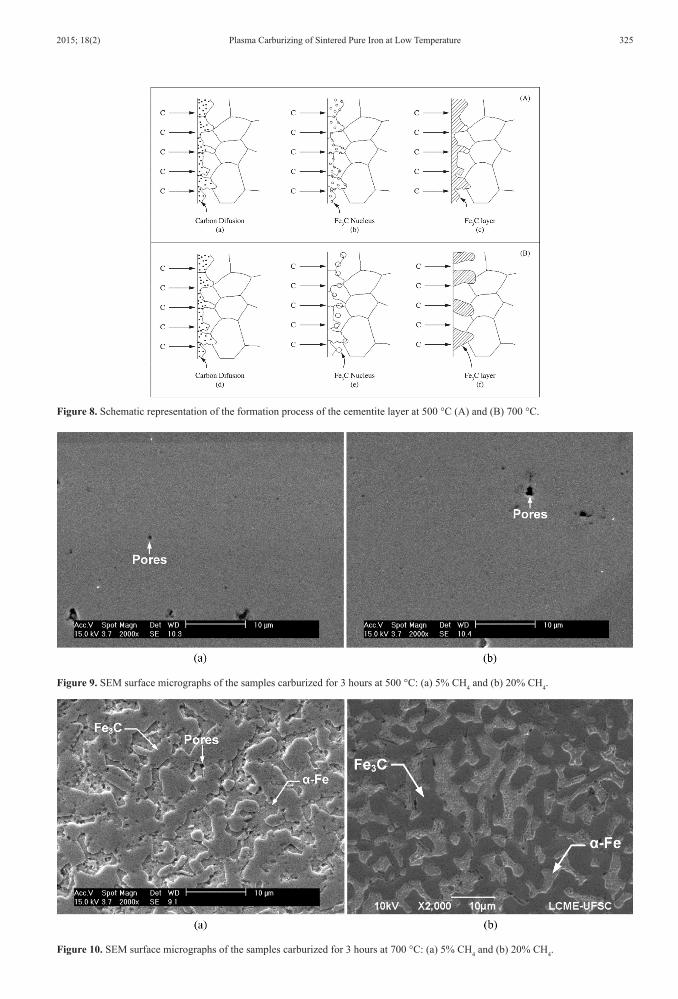
Figure 10 shows the topography of the samples carburized at 700 °C. A discontinuous surface apparently composed of two phases is observed at the sample submitted to that temperature, as already evidenced in the cross-sectional analysis of these samples. Relating the cross-sectional micrographs (Figure 6) to the surface micrographs (Figure 10), it is believed that the layer of cementite is formed by large particles, which appear to form “islands” on the iron substrate and probably coalesce during the treatment. This type of island formation is similar to the Volmer-Weber theory of film growth, which describes the formation of an island or irregular layer when the sum of the surface free energy of the adsorbed layer A( ) γ and the interface free energy between adsorbed/substrate layers As( )γ is greater than or equal to that of the substrate S( ) :γ
( )A As S γ + γ ≥ γ [28] (1)
These surface images also confirm that a lower methane percentage in the gas mixture allowed the formation of particles that are more coalesced after carburizing, as shown in Figure 10a. Another important observation is that in regions where the surface porosity is not sealed, the layer is irregular and porous in morphology.
Samples carburized at 500 °C have the potential to be utilized in applications where high wear resistance and good corrosion properties are required because these
Figure 6. Cross-sectional micrographs of samples carburized at 700 °C: (a) 5% CH4 and (b) 20% CH4.
Figure 7. X-ray diffraction patterns for the samples carburized at 500 °C and 700 °C with 5% CH4 for 3 hours.
Plasma Carburizing of Sintered Pure Iron at Low Temperature2015; 18(2) 325
Figure 8. Schematic representation of the formation process of the cementite layer at 500 °C (A) and (B) 700 °C.
Figure 9. SEM surface micrographs of the samples carburized for 3 hours at 500 °C: (a) 5% CH4 and (b) 20% CH4.
Figure 10. SEM surface micrographs of the samples carburized for 3 hours at 700 °C: (a) 5% CH4 and (b) 20% CH4.

Lamim et al.326 Materials Research
carburized layers are continuous along the entire surface. In contrast, carburizing at 700 °C has the potential to be useful in applications that require high wear resistance with high tenacity once the cementite has a sufficiently high hardness to resist the wear and the ferrite has a high tenacity to absorb the impact. According to Marcos29, when there is a discontinuous layer, however regular, on a surface of a material, a combination of the mechanical properties of the two different phases exists (Figure 10). This treatment is known as surface structuration.
Figure 11 shows the results of the microhardness measurements of the surface and the microhardness profile of the samples carburized at 500 °C and 700 °C for 3 hours with 5% of CH4 in the gas mixture. The surface hardness values are those where the depth is zero (top hardness).
Initially, the hardness of the samples carburized at 500 °C (118.80 HV) are found not to have a considerable difference compared with the samples that were not carburized (sintered pure iron: 103.93 HV). If the variability of these carburizing conditions is considered, they are statistically identical. This similarity may be associated with the morphology of this layer, a very thin and hard layer (cementite) on a ductile substrate (pure iron), which would result in breaking of the cementite layer and its hardness value being determined by the substrate.
According to Jönsson & Hogmark30, when the relation between depth and film thickness (P⁄e) exceeds a critical value between 0.07 and 0.2, the hardness measurement is influenced by the substrate and is not characterized by the real film hardness. Ratios (P⁄e) above 2.0 were found for samples carburized at 500 °C, thus confirming the substrate influence on the hardness values measured.
For samples carburized at 700 °C, a high variability in the measurements is observed, not converging to a conclusive hardness value that could characterize these layers. This high dispersion is related to the irregular morphology of the layers formed at this temperature that presents cementite particles and ferrite exposed on the surface of the samples.
Despite the high dispersion in the measurements, the samples carburized at 700 °C exhibited some hardness values similar to the hardness of cementite layers on iron substrates formed by plasma carburizing described in17-19. This behavior
may be an indication that some cementite particles were more coalesced at that methane percentage, allowing for a reduced influence of the substrate on the measurements.
Figure 11 shows no difference between the microhardness profile of the carburized layer at 500 °C to the iron substrate. Thus if there was diffusion at this treatment temperature, it was not sufficient to increase the hardness of the material. In addition, the highest hardness values observed in the profile of the samples carburized at 700 °C may be related to the largest cementite particles on the surface of these samples and also to the presence of a diffusion layer.
4. ConclusionsThis work was performed to examine the formation of a
cementite layer during plasma carburizing at low temperatures (500 °C and 700 °C) in sintered unalloyed iron. The primary conclusions are listed below:
• Plasma carburizing at low temperatures can be used to obtain a polycrystalline cementite layer.
• Carburizing at 500 °C promotes the formation of a thin and continuous cementite layer along the entire surface, which should be associated with the low diffusivity and solubility of the carbon into α-Fe at this temperature.
• The methane content did not exhibit any influence on the cementite layer at 500 °C, indicating that carbon saturation on the surface was obtained with 5% methane.
• The increase in the treatment time from 3 to 6 hours leads to a doubling of the thickness of the cementite layer, indicating the linear relation between the layer growth and the treatment time.
• At 700 °C, an irregular layer is formed on the surface of the samples. This layer is formed by “islands” or particles of cementite, which tend to coalesce during the carburizing treatment.
• At 700 °C the increase in the methane percentage promotes a layer surface in which the particles are less coalesced. The mechanism of formation of these layers is also associated with the low solubility of the carbon in α-Fe. However, the thicker particles that are observed are related to higher diffusivity at this temperature.
• It was observed a substrate influence on the surface hardness of the samples carburized at 500 °C and a high dispersion on the surface hardness to the samples carburized at 700 °C. Thus the microhardness technique is not proper to probe the hardness of the layers obtained at this work.
AcknowledgementsThis research was supported by the CNPQ by way
of a scholarship. The authors thank the Laboratory of Microstructural Characterization (LCM) from the Universidade Federal de Santa Catarina (UFSC) for the use of the X-ray diffractometer, the LCME-UFSC for technical support during electron microscopy work and the Materials Laboratory (Labmat) from UFSC for the availability of all necessary equipment for the plasma carburizing treatments.
Figure 11. Microhardness profile of the layers carburized at 500 °C and 700 °C for 3 hours with 5% CH4.

Plasma Carburizing of Sintered Pure Iron at Low Temperature2015; 18(2) 327
References1. Klein AN, Cardoso RP, Pavanati HC, Binder C, Maliska AM,
Hammes G, et al. DC Plasma Technology Applied to Powder Metallurgy: an Overview. Plasma Sci. Technol. 2013; 15(1):70-81. http://dx.doi.org/10.1088/1009-0630/15/1/12.
2. Araújo VB. Estudo das potencialidades do processo de cementação a plasma sem aquecimento auxiliar. [Tese]. Universidade Federal de Santa Catarina; 1999.
3. Borba E, Maliska AM, Souza A and Klein AN. Plasma nitriding and nitrocarburising in sintered materials. Materials Science Forum. 1999; 299-300:321-329. http://dx.doi.org/10.4028/www.scientific.net/MSF.299-300.321.
4. Enje N, Karbidov T and Enje KU. Carburization, carbide formation, metal dusting, coking. Mater Tehnol. 2002; 36(6):297-305.
5. Bendo T, Pavanati HC, Klein AN, Martinelli AE and Maliska AM. Plasma Nitriding of Surface Mo-Enriched Sintered Iron. ISRN Materials Science. 2011; 2011:1-8. http://dx.doi.org/10.5402/2011/121464.
6. Edenhofer BU, Grafen W and Müller-Ziller J. Plasma-carburising a surface heat treatment process for the new century. Surface and Coatings Technology. 2001; 142-144:225-234. http://dx.doi.org/10.1016/S0257-8972(01)01136-7.
7. Rie KT. Recent advances in plasma diffusion processes. Surface and Coatings Technology. 1999; 112(1-3):56-62. http://dx.doi.org/10.1016/S0257-8972(98)00747-6.
8. Pehlivanturk NY, Inal OT and Ozbaysal K. Plasma or ion carburizing of several steels. Technol. Coatings. 1988; 35(3-4):309-320. http://dx.doi.org/10.1016/0257-8972(88)90044-8.
9. Jacobs MH. The mechanism and kinetics of carbon transport into iron and steel during plasma carburizing. ISPC. 1983; 6:737-742.
10. Okumiya M, Tsunekawa Y, Matsumoto T, Tanaka K and Nagai T. Carbon content control in plasma carburizing using process parameter and probe methods. Surface and Coatings Technology. 2003; 174-175:1171-1174. http://dx.doi.org/10.1016/S0257-8972(03)00531-0.
11. Baek JMU, Cho YR, Kim DJ and Lee KH. Plasma carburizing process for the low distortion of automobile gears. Surface and Coatings Technology. 2000; 131(1-3):568-573. http://dx.doi.org/10.1016/S0257-8972(00)00777-5.
12. Souza RM, Ignat M, Pinedo CE and Tschiptschin AP. Structure and properties of low temperature plasma carburized austenitic stainless steels. Surface and Coatings Technology. 2009; 204(6-7):1102-1105. http://dx.doi.org/10.1016/j.surfcoat.2009.04.033.
13. Sun Y. Kinetics of low temperature plasma carburizing of austenitic stainless steels. Journal of Materials Processing Technology. 2005; 168(2):189-194. http://dx.doi.org/10.1016/j.jmatprotec.2004.10.005.
14. Scheuer CJ. Cementação a baixa temperatura do aço inoxidável martensítico AISI 420 assistida por plasma. [Dissertação]. UFPR; 2011.
15. Scheuer CJ, Cardoso RP, Pereira R, Mafra M and Brunatto SF. Low temperature plasma carburizing of martensitic stainless steel. Materials Science and Engineering A. 2012; 539:369-372. http://dx.doi.org/10.1016/j.msea.2012.01.085.
16. Siriwardane H, Pringle OA, Newkirk JW and James WJ. Microstructure and physical properties of iron carbide films formed by plasma enhanced chemical vapor deposition CO-REACTING. Thin Solid Films. 1996; 287(1-2):8-15. http://dx.doi.org/10.1016/S0040-6090(96)08555-0.
17. Li JL, O’Keefe TJ and James WJ. Iron Carbide Films Formed by Plasma Deposition and Plasma Carburizing. Materials Science and Engineering B. 1990; 7(1-2):15-23. http://dx.doi.org/10.1016/0921-5107(90)90004-U.
18. Carpene E and Schaaf P. Formation of Fe3C surface layers by laser plasma cementation. Applied Physics Letters. 2002; 80(5):891. http://dx.doi.org/10.1063/1.1447009.
19. Schaaf P, Kahle M and Carpene E. Reactive laser plasma coating formation. Surface and Coatings Technology. 2005; 200(1-4):608-611. http://dx.doi.org/10.1016/j.surfcoat.2005.01.028.
20. Schneider A and Inden G. Carbon diffusion in cementite (Fe3C) and Hägg carbide (Fe5C2). Calphad. 2007; 31(1):141-147. http://dx.doi.org/10.1016/j.calphad.2006.07.008.
21. Maliska AM, Oliveira AM, Klein AN and Muzart JLR. Surface porosity sealing effect of plasma nitrocarburizing on sintered unalloyed iron. Surface and Coatings Technology. 2001; 141(2-3):128-134. http://dx.doi.org/10.1016/S0257-8972(01)01016-7.
22. Tuinstra F and Koenig JL. Raman Spectrum of Graphite. The Journal of Chemical Physics. 1970; 53(3):1126. http://dx.doi.org/10.1063/1.1674108.
23. Chieu TC, Dresselhaus M and Endo M. Raman studies of benzene-derived graphite fibers. Physical Review B: Condensed Matter and Materials Physics. 1982; 26(10):5867. http://dx.doi.org/10.1103/PhysRevB.26.5867.
24. Söderström O. In situ studies of carbon formation leading to metal dusting in syngas processes. Lund; 2010.
25. Schneider A. Iron layer formation during cementite decomposition in carburising atmospheres. Corrosion Science. 2002; 44(10):2353-2365. http://dx.doi.org/10.1016/S0010-938X(02)00044-6.
26. Rembges K and Luhr J. Carburizing: Processing and performance. ASTM International; 1989.
27. Edenhofer B. Physical and metallurgical aspects of ion nitriding –. Heat Treat. Met. 1974; 1:23-28.
28. Nieminen JA and Kaski K. Criteria for different growth mode of thin films. Surface Science Letters. 1987; 185(1-2):489-496. http://dx.doi.org/10.1016/0167-2584(87)90291-X.
29. Marcos G, Guilet S, Cleymand F, Thiriet T and Czerwiec T. Stainless steel patterning by combination of micro-patterning and driven strain produced by plasma assisted nitriding. Surface and Coatings Technology. 2011; 205:S275-S279. http://dx.doi.org/10.1016/j.surfcoat.2011.01.016.
30. Jönsson B and Hogmark S. Hardness measurement of thin films. Thin Solid Films. 1984; 114(3):257-269. http://dx.doi.org/10.1016/0040-6090(84)90123-8.

DOI: http://dx.doi.org/10.1590/1516-1439.306514erMaterials Research. ©
Erratum
In the article “Plasma Carburizing of Sintered Pure Iron at Low Temperature”, DOI number: <http://dx.doi.org/10.1590/1516-1439.306514>, published in Mater. Res., March-April 2015, 18(2): 320-327, in page 320 where the author’s names were:
“Thiago de Souza Lamim, Euclides Alexandre Benardelli, Cristiano Binder, Aloisio Nelmo Klein, Ana Maria Maliska”
It should be written:
“Thiago de Souza Lamim, Euclides Alexandre Bernardelli, Cristiano Binder, Aloisio Nelmo Klein, Ana Maria Maliska”