Embed Size (px)
Citation preview
www.elsevier.com/locate/surfcoat
Surface & Coatings Technology
Plasma diagnostical comparison of the MSIP process of (Ti,Al)N with
pulsed and dc power supplies using energy-resolved mass spectroscopy
E. Lugscheider, K. Bobzin, N. Papenfug-Janzen*, M. Maes, D. Parkot
Materials Science Institute, RWTH Aachen University, Augustinerbach 4-22, 52062 Aachen, Germany
Available online 11 September 2004
Abstract
Plasma diagnostics by energy-resolved mass spectroscopy is a well-known method to understand and control rf plasmas, e.g. during
plasma etching, and PECVD processes. Only very few scientific work concentrates on the investigation of the magnetron sputter ion plating
(MSIP) process. This is the reason why, so far, this process is not very well understood. A technology that has been gaining increasing
importance within the last decade is the use of pulsed power supplies. On the one hand, this technology allows the sputtering of insulating
coatings with a significantly higher sputtering rate than with rf plasma. On the other hand, the degree of ionization is higher than in dc
processes. In this article, the ion energy distribution of aluminum and titanium as well as titanium nitride is observed by using a pulsed
cathode power supply and a dc power supply. The different behavior of the ion energy distributions depending on the power supplies is
shown. The cathode power and the nitrogen flow are the observed varying process parameters.
D 2004 Elsevier B.V. All rights reserved.
Keywords: MSIP process; dc process; Pulsed process
1. Introduction
The magnetron sputter ion plating (MSIP) process is a
common technology to apply thin hardcoatings against wear
and corrosion as well as optical coatings. Although the
technology is established for industrial applications, the
physical processes have not been investigated sufficiently,
yet. Therefore, MSIP is mainly based on experience.
Mass spectroscopy is well known for the diagnostics of rf
plasma processes, e.g. Refs. [1–6]. However, only a few
articles [7–10] on dc and pulsed sputtering of titanium- or
chromium-based coatings have been published, yet. A first
extensive investigation of all aspects of the MSIP process
has been gathered in Ref. [11].
In this article, the analysis of the plasma inside the MSIP
coating unit CC 800R/9 by CemeCon AG at the Materials
Science Institute of the RWTH Aachen University for a
0257-8972/$ - see front matter D 2004 Elsevier B.V. All rights reserved.
doi:10.1016/j.surfcoat.2004.08.011
* Corresponding author. Tel.: +49 241 8096512; fax: +49 241
8092264.
E-mail address: [email protected]
(N. Papenfug-Janzen).
(Ti,Al)N hardcoating process is presented. A mass spec-
trometer EQP 300 by HIDEN Analytical was used to
measure the ion energy distributions of titanium, aluminum
and titanium nitride. The cathode power and the nitrogen
flow are the variable process parameters. A dc power supply
MDX Pinnacle and a sinusoidal pulsed PEII, both by
Advanced Energy, were applied. The plasma characteristics
of these supplies were compared to find possible reasons for
the much better coating properties when using pulsed
plasma.
2. Experimental
For the presented work a HIDEN EQP 300 mass
spectrometer (Fig. 1) was used, which was described by
Budtz-Jbrgensen [12]. The HIDEN EQP 300 consists of five
main sections. The functions of those sections shall briefly
be explained. The extraction section consists of the extractor
and the lens 1. In this part, the ions and neutrals that pass the
orifice have to be directed towards the detector. The
ionization source is only needed when measurements in
188–189 (2004) 164–167

Fig. 1. Assembly of the HIDEN EQP 300 [12].
E. Lugscheider et al. / Surface & Coatings Technology 188–189 (2004) 164–167 165
the RGA mode are conducted. Then, neutral particles are
ionized by a dual-filament electron impact ionization source.
The deceleration section consists of the axis, the lens 2 and
the quadrupole lens. This section is needed to decelerate the
ions to an energy of about 40 eV. Only at this low kinetic
energy ions can pass the 458 bend to the analyzer. The
energy filter is a 458 sector field energy analyzer, where ionsare deflected by an electric field depending on their kinetic
energy when the particles enter the section field. The last
part of the HIDEN EQP 300 is the mass filter. This filter is a
quadrupole mass spectrometer consisting of four metal rods
with a superposed dc and rf voltage. Only particles with a
special mass-to-charge ratio can pass this filter and can be
detected, while the other m/q ratios are removed by the rf
field and the dc field, respectively.
Table 1
Process parameters to investigate the nitrogen influence
Ar flow
[mln/min]
N2 flow
[mln/min]
Kr flow
[mln/min]
Power per
cathode [W]
100 0 100 2000
100 75 100 2000
100 100 100 2000
100 127 100 2000
100 150 100 2000
100 175 100 2000
Table 2
Process parameters to investigate the cathode power influence
Ar flow
[mln/min]
N2 flow
[mln/min]
Kr flow
[mln/min]
Power per
cathode [W]
100 127 100 1000
100 127 100 1500
100 127 100 2000
100 127 100 2500
The measurements were carried out at the Materials
Science Institute at the RWTH Aachen University on an
MSIP coating unit of the type CemeCon CC 800R/9 with
four cathodes CK 588. The mass spectrometer was
positioned parallel to one cathode with a distance of about
80 mm for the presented experiments. The observed coating
material was (Ti,Al)N, produced by the magnetron sputter-
ing of two-component Ti–Al targets with nitrogen as a
reactive gas. Argon and krypton were used as process gases.
The pulsed plasma experiments were conducted by using
two sinusoidal pulsed power supplies of the type PE II by
Advanced Energy. Two cathodes got a sinusoidal negative
voltage, while the corresponding cathodes were discharged.
The output frequency was 40 kHz. First results concerning
the use of this technology on (Cr,Al) N coatings were
presented, recently [9,10].
The mass spectroscopy measurements were conducted in
the SIMS mode (Secondary Ion Mass Spectroscopy).
0 5 10 15 20 25 30
0 mln/min N2
75 mln/min N2
100 mln/min N2
127 mln/min N2
150 mln/min N2
175 mln/min N2
co
un
tin
g r
ate
[H
z]
energy [eV]
107
106
105
104
103
27 Al+
Fig. 2. Energy distribution of Al+ ions for different N2 flows in the dc
process.

0 5 10 15 20 25 30
N2 flow 0 mln/min
N2 flow 75 mln/min
N2 flow 100 mln/min
N2 flow 127 mln/min
N2 flow 150 mln/min
N2 flow 175 mln/min
co
un
tin
g r
ate
[H
z]
energy [eV]
107
106
105
104
103
27 Al+
Fig. 3. Energy distribution of Al+ ions for different N2 flows in the pulsed
process.
0 120 140 160 180 200
Pulsed
DC
2,0x10⁷
1,5x10⁷
1,0x10⁷
5,0x10⁶
0,020 40 60 80 100
po
we
r [e
V/s
]
N2-flow [mln/min]
48 Ti+
Fig. 5. N2 flow dependence of the integral of the energy distributions of Ti+
in the dc and the pulsed process.
E. Lugscheider et al. / Surface & Coatings Technology 188–189 (2004) 164–167166
Therefore, only ions were detected and no further ionization
of neutral particles was forced by high-energy electrons.
The orifice was electrically charged with a �5 V voltage.
In order to investigate the influence of the nitrogen flow,
the process parameters were chosen from Table 1, whereas
the parameters from Table 2 were used to observe the
influence of the cathode power. The process parameters
were unchanged for the dc and the pulsed processes,
respectively.
3. Results
First, the influence of the nitrogen flow was observed.
The energy distributions of Al+ ions are presented in Fig. 2
for the dc process and in Fig. 3 for the pulsed process. It can
be seen that the target poisoning in the dc process is much
more obvious than in the pulsed process. Due to the large
decrease of the maximum of the distribution, the poisoning
can be located below 75 mln/min. The shape of the energy
distribution in the pulsed process is broader than in the dc
0 100 120 140 160 180
27 Al+
48 Ti+
62 TiN+
po
wer
[eV
/s]
N2-flow [mln/min]
107
106
105
104
103
102
20 40 60 80
Fig. 4. N2 flow dependence of the integral of the energy distributions of
Al+, Ti+ and TiN+ in the dc process.
process. Moreover, the energy of the ions is about 5 eV
higher than in the dc process.
In Fig. 4, the number of detected ions by means of the
integrals of the distributions is shown for Al+, Ti+ and TiN+
in the dc process. It can be observed that the number of
detected metallic ions first decreases, then increases after
passing a minimum. The reason for this is that initially the
nitrogen is a reactive gas, but after the poisoning of the
targets it becomes a process gas supporting the sputtering.
The energy of the nitrogen has not been measured, because
its number of detected ions exceeds the permitted measuring
range. Therefore, the settings of the EQP would have been
changed. However, this would lead to incomparable data.
Contrary to Ref. [7], nitride ions could be observed in the
process with a content of about 1% of the metallic ions.
Although the aluminum fraction in a coating is lower than
the titanium fraction, the number of detected aluminum ions
is higher. This can be explained by the lower ionization
energy of aluminum. The distribution of AlN+ is not shown
here, because it could be proven that ArH+ is formed during
the process [11]. AlN+ and ArH+ have the same mass-to-
0 100 120 140 160 180 2000
Pulsed
DC
po
wer
[eV
/s]
N2-flow [mln/min]
4x10⁵
3x10⁵
2x10⁵
1x10⁵
20 40 60 80
62 TiN+
Fig. 6. N2 flow dependence of the integral of the energy distributions of
TiN+ in the dc and the pulsed process.
2500
DC
Pulsed
po
we
r [e
V/s
]
power/cathode [W]
5,0x10⁶
4,5x10⁶
4,0x10⁶
3,5x10⁶
3,0x10⁶
2,5x10⁶
2,0x10⁶
1,5x10⁶
1,0x10⁶
1000 1500 2000
48 Ti+
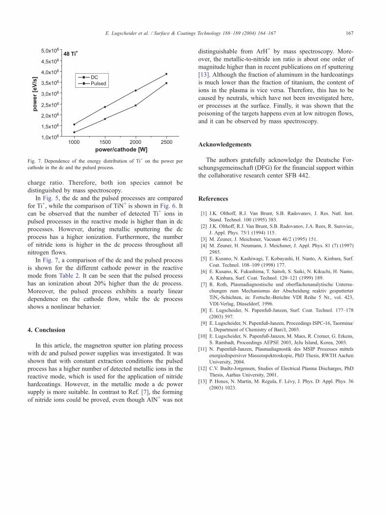
Fig. 7. Dependence of the energy distribution of Ti+ on the power per
cathode in the dc and the pulsed process.
E. Lugscheider et al. / Surface & Coatings Technology 188–189 (2004) 164–167 167
charge ratio. Therefore, both ion species cannot be
distinguished by mass spectroscopy.
In Fig. 5, the dc and the pulsed processes are compared
for Ti+, while the comparison of TiN+ is shown in Fig. 6. It
can be observed that the number of detected Ti+ ions in
pulsed processes in the reactive mode is higher than in dc
processes. However, during metallic sputtering the dc
process has a higher ionization. Furthermore, the number
of nitride ions is higher in the dc process throughout all
nitrogen flows.
In Fig. 7, a comparison of the dc and the pulsed process
is shown for the different cathode power in the reactive
mode from Table 2. It can be seen that the pulsed process
has an ionization about 20% higher than the dc process.
Moreover, the pulsed process exhibits a nearly linear
dependence on the cathode flow, while the dc process
shows a nonlinear behavior.
4. Conclusion
In this article, the magnetron sputter ion plating process
with dc and pulsed power supplies was investigated. It was
shown that with constant extraction conditions the pulsed
process has a higher number of detected metallic ions in the
reactive mode, which is used for the application of nitride
hardcoatings. However, in the metallic mode a dc power
supply is more suitable. In contrast to Ref. [7], the forming
of nitride ions could be proved, even though AlN+ was not
distinguishable from ArH+ by mass spectroscopy. More-
over, the metallic-to-nitride ion ratio is about one order of
magnitude higher than in recent publications on rf sputtering
[13]. Although the fraction of aluminum in the hardcoatings
is much lower than the fraction of titanium, the content of
ions in the plasma is vice versa. Therefore, this has to be
caused by neutrals, which have not been investigated here,
or processes at the surface. Finally, it was shown that the
poisoning of the targets happens even at low nitrogen flows,
and it can be observed by mass spectroscopy.
Acknowledgements
The authors gratefully acknowledge the Deutsche For-
schungsgemeinschaft (DFG) for the financial support within
the collaborative research center SFB 442.
References
[1] J.K. Olthoff, R.J. Van Brunt, S.B. Radovanov, J. Res. Natl. Inst.
Stand. Technol. 100 (1995) 383.
[2] J.K. Olthoff, R.J. Van Brunt, S.B. Radovanov, J.A. Rees, R. Suroviec,
J. Appl. Phys. 75/1 (1994) 115.
[3] M. Zeuner, J. Meichsner, Vacuum 46/2 (1995) 151.
[4] M. Zeuner, H. Neumann, J. Meichsner, J. Appl. Phys. 81 (7) (1997)
2985.
[5] E. Kusano, N. Kashiwagi, T. Kobayashi, H. Nanto, A. Kinbara, Surf.
Coat. Technol. 108–109 (1998) 177.
[6] E. Kusano, K. Fukushima, T. Saitoh, S. Saiki, N. Kikuchi, H. Nanto,
A. Kinbara, Surf. Coat. Technol. 120–121 (1999) 189.
[7] R. Roth, Plasmadiagnostische und oberfl7chenanalytische Untersu-
chungen zum Mechanismus der Abscheidung reaktiv gesputterter
TiNx-Schichten, in: Fortschr.-Berichte VDI Reihe 5 Nr., vol. 423,
VDI-Verlag, Dqsseldorf, 1996.[8] E. Lugscheider, N. Papenfug-Janzen, Surf. Coat. Technol. 177–178
(2003) 597.
[9] E. Lugscheider, N. Papenfug-Janzen, Proceedings ISPC-16, Taormina/
I, Department of Chemistry of Bari/I, 2003.
[10] E. Lugscheider, N. Papenfug-Janzen, M. Maes, R. Cremer, G. Erkens,
S. Rambadt, Proceedings AEPSE 2003, JeJu Island, Korea, 2003.
[11] N. Papenfug-Janzen, Plasmadiagnostik des MSIP Prozesses mittels
energiedispersiver Massenspektroskopie, PhD Thesis, RWTH Aachen
University, 2004.
[12] C.V. Budtz-Jbrgensen, Studies of Electrical Plasma Discharges, PhD
Thesis, Aarhus University, 2001.
[13] P. Hones, N. Martin, M. Regula, F. Levy, J. Phys. D: Appl. Phys. 36
(2003) 1023.