Embed Size (px)
Citation preview
Plasma transport near the separatrix of a magnetic
island
R. D. Hazeltine1, P. Helander2, and Peter J. Catto3
1Institute for Fusion Studies, The University of Texas at Austin,Austin, TX 78712, U.S.A.
2UKAEA, Fusion (UKAEA/Euratom Fusion Association), Culham,Abingdon, Oxon, OX14 3DB, U.K.
3Massachusetts Institute of Technology, Plasma Fusion Center,Cambridge, MA 02139, U.S.A.
Abstract
The simplest non-trivial model of transport across a magnetic island chain in the pres-
ence of collisionless streaming along the magnetic field is solved by a Wiener-Hopf procedure.
The solution found is valid provided the boundary layer about the island separatrix is nar-
row compared to the island width. The result demonstrates that when this assumption is
satisfied the flattened profile region is reduced by the boundary layer width. The calculation
is similar to the recent work by Fitzpatrick [R. Fitzpatrick, Phys. Plasmas 2, 825 (1995)]
but is carried out in the collisionless, rather than the collisional, limit of parallel transport,
and determines the plasma parameters on the separatrix self-consistently.
PACS Nos.: 52.25.Fi, 52.40.Hf, 52.55.Fa
1
I. Introduction
The dynamics of magnetic islands in tokamaks is currently a topic of intense research.
It was shown by Carrera, Hazeltine, and Kotschenreuther,1 and by Qu and Callen,2 that
perturbing the bootstrap current caused by an island tends to make the island grow further
(if the magnetic shear is positive), thus providing a powerful drive for instability. More recent
calculations3,4 have included the effect of the ion polarization drift, which was shown to be
able to stabilize sufficiently narrow islands. However, islands whose initial width exceeds
some threshold grow because of the bootstrap drive. Such a threshold appears to have been
observed experimentally in the Tokamak Fusion Test Reactor (TFTR).5 The need to re-
examine the existence of a threshold due to the ion polarization drift has also been pointed
out.6
An alternative explanation of the threshold has recently been proposed by Fitzpatrick,7
and Gorelenkov and co-workers,8 who point out that the density and temperature profiles are
not flattened across a sufficiently narrow island because of cross-field transport. The boot-
strap current is therefore not significantly perturbed and the instability drive never appears.
Fitzpatrick7 also discussed the detection of magnetic islands by electron cyclotron emision
and argued that a narrow island should be virtually undetectable because the electron tem-
perature profile is not flattened over the island. In contrast, the earlier calculations1–4 consid-
ered islands wide enough to cause complete flattening of the profiles by ignoring the details
of the boundary layer about the island separatrix.
The transport properties associated with the plasma in the neighborhood of a magnetic
island are important, especially as the nonlinear growth of magnetic islands poses a serious
threat to the development of reactor relevant devices. Experiments are planned in a number
of existing tokamaks to apply localized current drive and heating to control the growth of
2
islands.
The purpose of the present paper is to clarify the nature of transport across a magnetic
island by solving a simplified kinetic equation in full island geometry. For simplicity we
treat only the limit of large island width, in which the transport boundary layer surrounding
the island separatrix is narrow in comparison with the island—a limit considered in all the
aforementioned theoretical papers. Even this problem is mathematically non-trivial because
the magnetic field lines change topology across the separatrix and because boundary data
cannot be specified on the separatrix itself.
Our calculation demonstrates the essential features of transport across a magnetic island,
which enforce a certain structure on spatial gradients in the island vicinity. While the paper
by Fitzpatrick7 considers cross-field transport in the limit of collisional parallel transport, we
are interested in the opposite, collisionless limit more relevant to high temperature plasmas.
This limit was treated in the paper by Gorelenkov et al.,8 who, however, did not solve the
transport equation in the boundary layer.
In Sec. II, the model kinetic equation is presented and the formalism necessary for dealing
with the island geometry is developed. In the following four sections, the boundary conditions
are discussed and the equation is solved by a Wiener-Hopf technique,9,10 with the details of
the factorization given in Sec. V and the results presented in Sec. VI. These results are
summarized in the last section.
II. Island coordinates
We suppose that diffusion across flux surfaces competes on an equal footing with free
streaming along the magnetic field. Guiding center drifts due to finite Larmor radius are
neglected. Hence we study the kinetic equation
v‖∇‖f = ∇ · (D∇f), (1)
3
where the ‖ subscript refers to the direction of the magnetic field B, f is the distribution
function and D is a diffusion coefficient. The diffusion is assumed to be caused by small-scale
plasma turbulence, and can be represented as in (1) if the characteristic time step in the
random walk taken by a particle in the turbulent field is shorter than the transit time around
the island.
Diffusion is ordinarily a much slower process than parallel streaming; the two processes
compete here only because the radial scale-length, w, of f—the scale-length for variation
normal to the magnetic flux surfaces—is assumed to be exceptionally short in the region of
interest. Thus we have the basic ordering
vtL‖∼ D
w2, (2)
where vt is the ion thermal speed and L‖ is the parallel scale length. This ordering is
conventional for tokamak boundary layers, such as that arising near a bounding wall; here
we apply it to the neighborhood of a magnetic island separatrix. The scale-length L‖ is the
characteristic length of a magnetic field line for one turn around the island, estimated in
Eq. (18) below. We suppose that this length is larger than the island width W , which, in
turn, exceeds the radial scale length w:
L‖ À W À w.
Toroidal curvature is not important for small W , so we can model the magnetic field
using cylindrical coordinates (r, β, z):
B = B0 [z + z×∇ψ(r, β)] . (3)
The z-axis gives the direction of the equilibrium field B0, r corresponds to the minor radius of
the torus and β is the helical angle on which the pertubation depends. The field perturbation
is introduced through its perturbed (helical) flux, measured by ψ.
4
Since the ψ in (3) has the dimensions of length, and since it satisfies
B · ∇ψ = 0,
we can use ψ as a radial coordinate in the perturbed field. Since we assume the distribution
to have helical symmetry, its natural coordinates are ψ and s,
f(r, β, z,v)→ f(ψ, s,v),
where s measures distance along B, and where
∂f
∂ψ∼(L‖w
)∂f
∂s.
It follows in particular that, to lowest order in w/W ,
∇ · (D∇f) ∼= D|∇ψ|2 ∂2f
∂ψ2
and our kinetic equation becomes
σu∂f
∂s= D|∇ψ|2 ∂
2f
∂ψ2(4)
where σ = ±1 is the sign of the parallel velocity and u = |v‖| its magnitude. We choose the
perturbation ψ to correspond to an m = 2 magnetic island (for concreteness):
ψ(r, β) =1
Ls(∆r2 −W 2 cos 2β) (5)
Here Ls is the shear length of the equilibrium field, W is the (half-) island width and
∆r ≡ r− a is the radial distance from the surface at r = a where islands are centered. Note
that ψ has the value W 2/Ls on the island separatrix. The field-line trajectories are given
by ∆r(ψ, β), where ψ labels the contour and β varies along it. It is convenient to introduce
k(ψ) where
k2 =Lsψ +W 2
2W 2.
5
Then we have
∆r(ψ, β) =√
2kW√
1− k−2 sin2 β (6)
We see that the region inside the island (where β has a limited range) corresponds to k < 1,
with k = 0 at the island magnetic axis and k = 1 at the separatrix.
In the next section we solve (4) by Fourier transformation in its radial variable. Here
we note that in its present form (4) is not amenable to Fourier transformation because its
coefficients are strong functions of radius. Although we assume, for simplicity,
D = constant,
the quantity ∇ψ necessarily varies from its nominal value, ψ/W , to zero at the island x-
points. Hence we introduce new, dimensionless coordinates (ψ, s)→ (x, θ) according to
∂θ
∂s≡ N(ψ)
D|∇ψ|2u
, (7)
∂x
∂ψ≡ N1/2(ψ), (8)
where the normalizing factor N is a slow function of ψ that will be chosen presently. We
shall see that the second term in
∂f
∂ψ=∂x
∂ψ
∂f
∂x+∂θ
∂ψ
∂f
∂θ(9)
makes a relatively small contribution (outside a very narrow neighborhood of the separatrix).
Hence the kinetic equation (4) is transformed into
∂f
∂θ= σ
∂2f
∂x2. (10)
for any choice of N .
We fix N by requiring θ to have a natural periodicity outside the island:
D
uN∫|∇ψ|2ds = π (11)
6
where the integral is performed at fixed ψ over a distance of one island length. Using
∇ = r∂
∂r+ βββ
1
a
∂
∂β,
we find that
|∇ψ|2 =4
L2s
(∆r2 +
W 4
a2sin2 2β
)
Because a ∼ L‖ À W the second term is small and neglected for simplicity. Then, since
ds = Bdβ
B · ∇β∼= aLs
2∆rdβ
our periodicity condition becomes
2aDN
uLs
∫ π/2
−π/2dβ∆r = π
or, in view of (6),
N =πuLs
4√
2aDWkE(k−2)(12)
where E is the complete elliptic integral of the second kind. Note that this quantity is finite
for k → 1.
Now (7) provides the angle variable (outside the island)
θ(ψ, β) =πE(β, k−2)
2E(k−2)(13)
in terms of the incomplete elliptic integral E(β, k−2).
Inside the island, (12) and (13) are meaningless, but we have a conventional prescription
for θ. First define φ(β, ψ) according to
sinφ ≡ k−1 sin β. (14)
and then use the identity
kE(β, k−2) = E(φ, k2) + (k2 − 1)F (φ, k2)
7
whose right-hand side is meaningful inside the separatrix. Here F is the incomplete elliptic
integral of the first kind. Thus, inside the island,
θ(ψ, β) =π
2
E(φ, k2) + (k2 − 1)F (φ, k2)
E(k2) + (k2 − 1)K(k2)(15)
where K is the complete elliptic integral of the first kind.
While the range of β is limited inside the island, (14) allows φ to vary from −π to π over
one loop of an interior surface. It can be seen to follow from (15) that θ also has the range
−π → π. Note that both angles remain well-defined at the island separatrix, except at the
endpoints where both suffer logarthmic singularity. Indeed, the definition of θ given by (13)
and (15) makes that function fully continuous across the separatrix. It is not a conventional
island angle, because of the |∇ψ|2-factor in (7). Without that factor the angle variable would
be singular on the island separatrix, where field lines become indefinitely long.
The radial variable is found from (8), which, because of the square root, allows a free
choice of signs. We choose x = 0 on the separatrix, and x > 0 inside it. The two separated
exterior regions, corresponding to r > a and r < a, will both have x < 0. Hence x(ψ) is
defined by
x(ψ) = 2
(π√2
)1/2 (uW 3
aDLs
)1/2 ∫ 1
k(ψ)
k1/2dk
[E(k−2)]1/2(16)
outside the island, and
x(ψ) = 2
(π√2
)1/2 (uW 3
aDLs
)1/2 ∫ 1
k(ψ)
kdk
[E(k2) + (k2 − 1)K(k2)]1/2(17)
inside.
These definitions do not distinguish the two regions outside the separatrix. In fact we
do so not through x but instead using θ: we associate the range −π < θ < 0 with the region
“below” the island chain (r < a), and the range 0 < θ < π with the upper region (r > a).
This arrangement is faithful to the true island topology provided we imagine the line along
θ = 0 for x < 0 to be an impenetrable barrier.
8
It is convenient at this point to re-examine our orderings. First note from (8) that the
layer width in ψ is measured by
∆ψ ∼ 1√N∼√aDW
vtLs
Alternatively we can estimate ∆ψ from (4) with the result
∆ψ ∼ W
Ls
√L‖D
vt.
The two expressions agree since
L‖ ∼aLsWÀ Ls. (18)
They are also consistent with the layer width measured in ordinary radius r,
w ∼ ∆ψ
∂ψ/∂r,
as can be seen from (2):
w ∼√DL‖vt
.
Figure 1 shows the resulting configuration. The island interior is labeled as region II; the
regions outside the separatrix, below and above the island chain, are labelled I and III
respectively.
A key assumption in the consistency of these estimates is that the separatrix layer be
thin compared to the island, w ¿ W . This requires an island of some size; in view of (18),
we must have
W À(aLsD
vt
)1/3
. (19)
When (19) is satisfied we can assume ∆r ∼ W and k ∼ 1 throughout the region of interest,
including the asymptotic domains where xÀ 1.
It remains to justify the neglect of the second term on the right in (9), which requires
∂ ln f
∂ψÀ ∂θ
∂ψ.
9
Since
∂ ln f
∂ψ=∂r
∂ψ
∂ ln f
∂r= O
(LsWw
),
∂θ
∂ψ=∂k2
∂ψ
∂θ
∂k2= O
(LsW 2
ln |1− k|)
this condition is equivalent to
ln |1− k| ¿ W/w,
which is satisfied everywhere but very close to the separatrix: it fails only in an exponentially
narrow [∼ exp(−W/w)] vicinity of the separatrix. The point is that the boundary layer
associated with the transport is considerably wider than this sublayer, which has do to
with the logarithmic singularity of the parallel scale length L‖. The kinetic equation (9) is
therefore sufficiently accurate for our purposes.
III. Boundary conditions
Of course the diffusion equation (10) is simple and conventional. What is distinctive
about island transport is the nature of the boundary conditions, which change across the
separatrix. Inside the separatrix, where x > 0, the distribution is periodic in θ with period
2π; outside the separatrix there are two separated regions, corresponding to r > a and r < a,
in which the period is π. Referring to Fig. 1 we can state the periodicity conditions on f(x, θ)
as
f(x,−π) = f(x, 0−), in region I; (20)
f(x,−π) = f(x, π), in region II; (21)
f(x, 0+) = f(x, π), in region III. (22)
Outside the island chain (but in its vicinity) we suppose that the distribution uniformly
increases in radius. It is the interruption of this constant gradient, by the island separatrices
10
and interior, that we wish to study. For convenience we consider the f in our kinetic equation
to be the difference between the actual distribution and its value, f0, at the island o-point;
this is permissible since (4) is unchanged by the addition of a (spatial) constant to f . Then,
outside the island chain, f(r, β) is odd with respect to the variable r−rs and f(x, θ) changes
sign across the barrier separating regions I and III:
f(x,−θ) = −f(x, θ), for x < 0. (23)
The change in boundary conditions across the separatrix forces the distribution to vary
with θ in a layer of width w surrounding the θ-axis. Outside that layer we expect f to
become constant on flux surfaces (independent of θ); the diffusion equation then requires f
to be linear in x for large x. Hence the asymptotic boundary conditions are
f(x, θ)→ 0, x→∞; (24)
f(x, θ)→ c1x+ c0, x→ −∞, θ < 0; (25)
f(x, θ)→−(c1x+ c0), x→ −∞, θ > 0. (26)
Note that, when viewed on the macroscopic scale, the distribution appears discontinuous
across the separatrix layer. It is this jump in f ,
∆f ≡ fIII − fI = −2c0 (27)
that drives the diffusion process being considered.
A salient conclusion of our analysis will be that the coefficients c0 and c1 cannot be
set independently by conditions far from the layer. Instead the diffusion equation with its
boundary data enforce a linear relation between them.
11
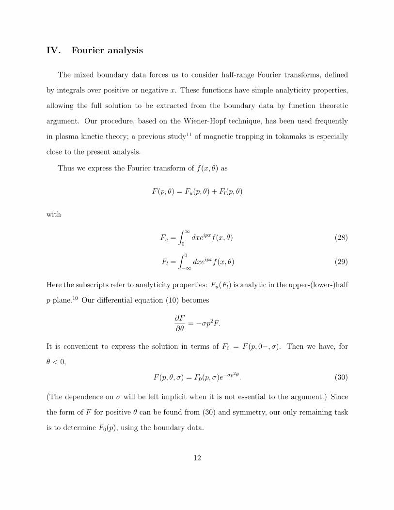
IV. Fourier analysis
The mixed boundary data forces us to consider half-range Fourier transforms, defined
by integrals over positive or negative x. These functions have simple analyticity properties,
allowing the full solution to be extracted from the boundary data by function theoretic
argument. Our procedure, based on the Wiener-Hopf technique, has been used frequently
in plasma kinetic theory; a previous study11 of magnetic trapping in tokamaks is especially
close to the present analysis.
Thus we express the Fourier transform of f(x, θ) as
F (p, θ) = Fu(p, θ) + Fl(p, θ)
with
Fu =∫ ∞
0dxeipxf(x, θ) (28)
Fl =∫ 0
−∞dxeipxf(x, θ) (29)
Here the subscripts refer to analyticity properties: Fu(Fl) is analytic in the upper-(lower-)half
p-plane.10 Our differential equation (10) becomes
∂F
∂θ= −σp2F.
It is convenient to express the solution in terms of F0 = F (p, 0−, σ). Then we have, for
θ < 0,
F (p, θ, σ) = F0(p, σ)e−σp2θ. (30)
(The dependence on σ will be left implicit when it is not essential to the argument.) Since
the form of F for positive θ can be found from (30) and symmetry, our only remaining task
is to determine F0(p), using the boundary data.
12

To simplify notation we introduce the abbreviations
U(p) = Fu(p,−π),
L(p) = Fl(p,−π),
M(p) = Fu(p, 0).
It can be seen that
F0 = e−πσp2
(U + L) (31)
so it suffices to determine U and L.
The large-x behavior of f , given by (24)–(26), fixes the small-p behavior of its transform;
in particular we find that
L(p)→ c1
p2− ic0
p, (32)
for p→ 0. On the other hand U(0) is finite.
We also observe that regularity of f(x, θ) at x = 0 requires both U and L to decay at
least as fast as 1/p for large |p|:
L ∼ U ∼ 1
p(33)
for |p| → ∞.
Considering next the angular data, we note that (20)–(22) imply
F (p,−π) = L+ U,
F (p, 0−) = L+M,
F (p, 0+) = −L+M,
F (p, π) = −L+ U
13
We combine these results with (30) to infer
L+M = (L+ U)e−πσp2
,
−L+ U = (−L+M)e−πσp2
.
or, after eliminating M ,
U(p)
L(p)= σV (p) (34)
where
V (p) ≡ tanhπp2
2.
The procedure starting from (34) is conventional.10 One supposes that V possesses a
Wiener-Hopf factorization of the form
V (p) =Vl(p)
Vu(p)(35)
where Vl (Vu) is analytic in the lower (upper) half p-plane, and where both factors are linear
in p for large p:
Vl ∼ Vu ∼ p, p→∞. (36)
Now (34) implies
U(p)Vu(p) = σL(p)Vl(p). (37)
The Wiener-Hopf argument then constructs a function A(p) that is defined by the left-hand
side of (37) in the upper half p-plane, and by its right-hand side in the lower half. Then
A(p) is analytic in the cut-plane; since (37) states that A is also continuous across the cut,
we can infer (under mild mathematical restrictions9) that A(p) is an entire function. But
note that (33) and (36) imply that A(p) approaches a constant, Cσ, for |p| → ∞. Since the
only entire function bounded by a constant at infinity is constant everywhere, we conclude
that
U(p) =CσVu(p)
, (38)
14
L(p) = σCσVl(p)
. (39)
Thus both functions U and L are determined from the single equation (34).
It is now clear that, as we have remarked, the coefficients c0 and c1 of (25) cannot be
independent: only a single free constant enters our expressions for U and L. From (32) we
see that the relation between c0 and c1 is fixed by the form of Vl for small p. Hence we need
to make the factorization explicit.
V. Factorization
We find the Wiener-Hopf factors Vu and Vl by a conventional procedure,9 observing first
that the function
V (z) =sinh(πz2/2)
cosh(πz2/2)
has poles at
z = ±√
2n+ 1eiπ/4,
and at
z = ±√
2n+ 1ei3π/4,
where n = 0, 1, 2, . . .. It has zeroes at
z = ±√
2neiπ/4,
and at
z = ±√
2nei3π/4.
Note that the zero at the origin (n = 0) is second order. It follows that the function
q(z) ≡ log
[(z2 + 1
z2
)V (z)
], (40)
15
is analytic and nonvanishing in a neighborhood of the real-z axis. Within this neighborhood
we construct the path Ca, parallel to the real axis but displaced a short distance above it,
in order to define
ql(p) ≡1
2πi
∫Cadz
q(z)
z − p.
It is clear that this function is analytic in the lower-half p-plane. Similarly we define
qu(p) ≡1
2πi
∫Cb
dzq(z)
z − pwhere the path Cb is displaced a short distance below the real axis. Since Cauchy’s theorem
implies
qu(p)− ql(p) = q(p)
we have found the relation (p2 + 1
p2
)V (p) = equ(p)−ql(p)
and it is straightforward to identify
Vl(p) = e−ql(p)p2
p− i , (41)
Vu(p) = e−qu(p)(p+ i). (42)
Notice that these functions have the asymptotic behavior anticipated in (36).
Recall that the asymptotic slope of the distribution near the layer is fixed by the behavior
of Vl(p) for small p. Therefore we consider the Taylor expansion of Vl:
Vl(p) = ie−ql(0)p2[1− ip− q′l(0)p+O(p2)
]. (43)
Here
q′l(0) ≡ dql(k)
dk|k=0
=1
2πi
∫Ca
dz
z2q(z)
=1
2πi
∫Ca
dz
zq′(z). (44)
16
From (40) we find
q′(z) =2z
z2 + 1− 2
z+
2πz
sinh πz2
so (44) yields
q′l(0) = −i− i∫Ca
dz
sinh πz2.
It is shown elsewhere11 that
∫Ca
dz
sinh πz2=√
2(√
2− 1)ζ(1/2)
where ζ denotes the Riemann zeta-function: ζ(1/2) ∼= −1.46. Substituting these results into
(43) we have
Vl(p) = ie−ql(0)p2[1 + i
√2(√
2− 1)ζ(1/2)p+O(p2)
]. (45)
It follows in particular that U ∝ V/Vl is finite at p = 0, as required.
We can also verify that the distribution becomes independent of θ for large x. The point
is that
∂f
∂θ=−σ2π
∫dpe−ipxp2F (p),
where p2F , unlike F itself, is regular for all real p. Hence phase-mixing will make its inverse
transform vanish for large x.
VI. Distribution function
Having determined
F0 = Cσe−πσp2
(1
Vu+ σ
1
Vl
)(46)
we could now in principle find the complete boundary layer distribution by inverse Fourier
transformation. However the resulting integration problem would bring scant reward, since
the details of layer structure have little observable effect. Hence we are content to point out
salient features of f(x, θ).
17
Note first that (46) can be expressed as
F0 =σCσVl(p)
[1 + σV (p)] e−σp2π
Thus, after straightforward manipulation using the explicit form of V (p), we can write the
Fourier transform of the distribution as
F (p, θ, σ) =σCσVl(p)
e−σp2(θ+π/2)
cosh(πp2/2)(47)
We next evaluate Cσ. Equation (32) fixes the small-p behavior of Vl according to
Vl(p) =σCσc1
p2(
1 +ic0
c1
p). (48)
Comparing this result to (45) we infer
α ≡ −c0
c1
= −√
2(√
2− 1)ζ(1/2) (49)
∼= 0.855, (50)
and
σCσ = −ic0
αe−ql(0).
To compute ql(0) we let the contour Ca approach the real axis and use the Plemelj formula
to conclude
ql(0) = −1
2log
π
2.
Thus
σCσ = −i√π/2
αc0 = −i1.46c0.
We expect the asymptotic distribution, c0, to be even in parallel velocity and therefore
infer
C+ = −C−. (51)
18
With (51) in mind we return to (47) and note the symmetry F (p, θ, σ) = F (p,−θ − π,−σ),
which implies
f(x, θ, σ) = f(x,−θ − π,−σ). (52)
This relation is consistent with the asymptotic boundary data.
More interesting is the relation (49) between the distribution outside the layer and its
slope. In a linear tearing mode, conditions inside the tearing layer determine the change in
asymptotic slope of the field perturbation, dψ/dx, across it; the value of ψ itself is continuous
across the layer. The present, nonlinear description of the distribution function is similar,
differing only in that the distribution itself, and not just its slope, will appear discontinuous
across the layer when viewed on the macroscopic scale. Thus macroscopic views of the upper
and lower separatrices, insensitive to the boundary layer structure, would show a jump in
the distribution:
∆f = −2c0
To characterize this jump we consider region I for definiteness; from (49),
∆f = 2c1α,
with
c1 =∂f
∂x=
1√N
∂f
∂ψ. (53)
Thus
∆f = 2α
(1√N
∂f
∂ψ
)I
(54)
Recalling that 1/√N = ∆ψ we obtain the estimate
∆f ∼ ∆ψ∂f
∂ψ∼ w
∂f
∂r.
The estimate is not surprising, but note that it involves only the layer width w, rather than
the much larger island width.
19
The same macroscopic view will ascribe the value
fs = f0 + c0
to the distribution function on the inner (region I) island separatrix. Here f0 denotes the
value of the distribution on the island o-point—the locally constant distribution that was
introduced to make f change sign across the island chain. It is consistent with our W À w
ordering to consider f0 as an experimentally measurable quantity. The slope of the distri-
bution as it approaches the separatrix in region I, according to (53), is
∂f
∂ψ= −√N
α(fs − f0)
with a corresponding expression in region III. Here, to lowest order in w/W , N can be
replaced by its value at k = 1,
N(1) =πuLs
4√
2aDW,
whence
∂f
∂ψ= −0.875
√uLsaDW
(fs − f0) (55)
We observe in particular that the gradient is steepest for rapidly streaming (large u) particles.
VII. Discussion
This work demonstrates rigorously an unsurprising circumstance: at low collisionality,
the change in the distribution function across an island chain occurs almost entirely in the
thin boundary layer surrounding each separatrix. Therefore, as long as the boundary layer is
small compared to the island width, the radial extent of the flattened profiles is proportional
to the island width, and the peak temperature and density that can be sustained in the
core for given edge values is reduced accordingly. For example, Tore-Supra12 employs an
ergodic divertor to widen the scrape-off layer (SOL) and thereby decreases the heat load
on the divertor plates. To avoid reducing the peak temperature and density that can be
20
sustained in the core, the width of the non-ergodic island chains adjacent to the SOL should
be kept comparable to or smaller than the boundary layer width about the island separatrix.
Similarly, islands generated by error or applied helical fields must be kept small to avoid
reducing the on-axis density and temperature for given edge values.
The present analysis of boundary-layer structure differs from a similar calculation by
Fitzpatrick7 in two ways. First, we consider the collisionless, rather than the collisional,
limit of transport along the field. Second, we do not impose boundary conditions on the
separatrix a priori but determine the conditions self-consistently. Our procedure resolves
details of boundary layer that affect the stability of islands in the core. Indeed, the stability
calculation by Wilson et al.4 shows that a significant fraction of the ion polarization current
originates inside the boundary layer, whose structure is therefore expected to influence the
final stability criterion in a more complete analysis—a topic we leave to future work.
Acknowledgments
We thank Frank Waelbroeck and Howard Wilson for comments on our manuscript. One
of the authors (PH) has benefitted from many discussions with Howard Wilson and from the
hospitality of the Plasma Fusion Center at Massachusetts Institute of Technology (MIT).
This work was funded by the U.S. Department of Energy Grants DE-FG02-91ER-54109 at
MIT and DE-FG03-96ER-54346 at The University of Texas at Austin, and jointly by the
UK Department of Trade and Industry and Euratom.
21
REFERENCES
1R. Carrera, R.D. Hazeltine, and M. Kotschenreuther, Phys. Fluids 29, 899 (1986).
2See National Technical Information Service Document No. DE6008946 (W.X. Qu and J.D.
Callen, University of Wisconsin Plasma Report No UWPR 85-5, 1985). Copies may be
ordered from the National Technical Information Service, Springfield, VA 22161.
3A.I. Smolyakov, Plasma Phys. Control. Fusion 35, 657 (1993).
4H.R. Wilson, J.W. Connor, R.J. Hastie, and C.C. Hegna, Phys. Plasmas 3, 248 (1996).
5Z. Chang, J.D. Callen, E.D. Fredrickson, R.V. Budny, C.C. Hegna, K.M. McGuire, M.C.
Zarnstorff, and the TFTR group, Phys. Rev. Lett. 74, 4663 (1995).
6F.L. Waelbroeck and R. Fitzpatrick, Phys. Rev. Lett. 78, 1703 (1997).
7R. Fitzpatrick, Phys. Plasmas 2, 825 (1995).
8N.N. Gorelenkov, R.V. Budny, Z. Chang, M.V. Gorelenkova, and L.E. Zakharov, Phys.
Plasmas 3, 3379 (1996).
9N.I. Muskhelishvili, Singular Integral Equations (Noordhoff, Groningen, 1953), p. 86.
10B. Noble, Methods Based on the Wiener-Hopf Technique (Pergamon, New York, 1958).
11R.D. Hazeltine and M. N. Rosenbluth, Phys. Fluids 15, 2211 (1972).
12C. de Michelis, A. Grosman, X. Garbet, P. Ghendrih, M. Goniche, W. Hess, C. Laviron,
T. Loarer, M. Mattioli, P. Monier-Garbet, B. Saoutic, F. Claret, D. Guirlet, G.T. Hoang,
and J. Lasalle, Nucl. Fusion 35, 1133 (1995).
22
FIGURE CAPTIONS
FIG. 1. The original island geomentry (a) and its rearrangement (b). Note the regions I,
below the island chain and outside its separatrix; II, inside the separatrix; and III,
above the island chain and outside its separatrix. The two structures are physically
equivalent provided the thick solid line in (b) is supposed to be impenetrable.
23