Embed Size (px)
Citation preview

MachMotion Version 1.0.1
MACHMOTION
Plasma/Oxy Torch
Operations Manual
Mark Worth
4/25/2012
Everything you need to know to configure and operate your plasma and/or oxy torch system.

P a g e | 1 MachMotion
Copyright © 2012, MachMotion.com
All rights reserved.
MachMotion
www.machmotion.com
14518 County Road 7240, Newburg, MO 65550
(573) 368-7399 •Fax (573) 341-2672

P a g e | 2 MachMotion
Contents 1 Control Overview .................................................................................................................................. 5
1.1 Screen Overview ........................................................................................................................... 5
1.2 Operator Panel Overview.............................................................................................................. 6
2 Homing and Jogging .............................................................................................................................. 7
2.1 Homing .......................................................................................................................................... 7
2.2 Jogging .......................................................................................................................................... 8
2.2.1 Jog On/Off ............................................................................................................................. 8
2.2.2 Jog Buttons ............................................................................................................................ 8
2.2.3 Jog Speed .............................................................................................................................. 8
2.2.4 Continuous and Step Jogging ............................................................................................... 8
3 Torch Control ........................................................................................................................................ 9
3.1 Tabs and Plasma and Oxy Fuel Mode Selection............................................................................ 9
3.2 Plasma Settings ............................................................................................................................. 9
3.2.1 THC ...................................................................................................................................... 10
3.2.2 Torch ................................................................................................................................... 10
3.2.3 Rip Cut ................................................................................................................................. 10
3.2.4 Pierce Counter .................................................................................................................... 11
3.2.5 Pierce Height ....................................................................................................................... 11
3.2.6 THC Height .......................................................................................................................... 11
3.2.7 Pierce Delay......................................................................................................................... 11
3.2.8 THC Delay ............................................................................................................................ 11
3.2.9 Ignition Height ..................................................................................................................... 11
3.2.10 Jog Speed ............................................................................................................................ 11
3.2.11 Ref Feed .............................................................................................................................. 11
3.3 Oxy Fuel Settings ......................................................................................................................... 12
3.3.1 Oxy Fuel PreHeat ................................................................................................................. 13
3.3.2 Oxy Fuel Cut ........................................................................................................................ 13
3.3.1 Rip Cut ................................................................................................................................. 13
3.3.2 Pierce Counter .................................................................................................................... 13
3.3.3 PreHeat Delay ..................................................................................................................... 14
3.3.4 Pierce Delay......................................................................................................................... 14
3.3.5 Cut Height ........................................................................................................................... 14
3.3.6 Jog Speed ............................................................................................................................ 14
4 Running Files ....................................................................................................................................... 15
4.1 Zeroing (Setting Part Zero) .......................................................................................................... 15
4.2 GOTO ........................................................................................................................................... 15
4.2.1 Load ..................................................................................................................................... 15
4.2.2 Part Zero .............................................................................................................................. 15
4.3 Loading G-Code Files ................................................................................................................... 15
4.3.1 G-Code Window .................................................................................................................. 15

P a g e | 3 MachMotion
4.3.2 Edit G-Code ......................................................................................................................... 15
4.3.3 Recent File ........................................................................................................................... 15
4.3.4 Close G-Code ....................................................................................................................... 16
4.3.5 Load G-Code ........................................................................................................................ 16
4.3.6 Set Next Line ....................................................................................................................... 16
4.3.7 Line ...................................................................................................................................... 16
4.3.8 Rewind ................................................................................................................................ 16
4.3.9 Single BLK ............................................................................................................................ 16
4.3.10 Block Delete ........................................................................................................................ 16
4.3.11 M1 Optional Stop ................................................................................................................ 16
4.4 Plate Alignment ........................................................................................................................... 16
4.5 Simulate ...................................................................................................................................... 17
4.6 Control Buttons ........................................................................................................................... 17
4.6.1 Cycle Start ........................................................................................................................... 17
4.6.2 Rewind ................................................................................................................................ 17
4.6.3 Reset ................................................................................................................................... 17
4.6.4 Stop ..................................................................................................................................... 17
5 Lost Cut Recovery ............................................................................................................................... 19
5.1 Lost Cut Recovery Overview ....................................................................................................... 19
5.2 Lost Cut Recovery Procedure ...................................................................................................... 20
5.2.1 Plasma – Auto ..................................................................................................................... 20
5.2.2 Plasma – Manual ................................................................................................................. 20
5.2.3 Oxy Fuel ............................................................................................................................... 21
5.2.4 Drill ...................................................................................................................................... 22
5.2.5 Plate Marker........................................................................................................................ 22
6 Appendix A – Button Definitions ........................................................................................................ 25
6.1 Feed Rate .................................................................................................................................... 25
6.2 Load Location .............................................................................................................................. 25
6.3 Max and Min THC ........................................................................................................................ 25
6.4 Pierce Reference Distance .......................................................................................................... 25
6.5 Plate Height Offset ...................................................................................................................... 25
6.6 Z Rapid Height ............................................................................................................................. 26
7 Appendix B – Diagnostics .................................................................................................................... 27
7.1 Tool Change Location .................................................................................................................. 27
7.2 Lost Arc Location ......................................................................................................................... 27
8 Appendix C – MDI and Program Limits ............................................................................................... 28
8.1 Program Limits ............................................................................................................................ 29
8.2 MDI .............................................................................................................................................. 29

P a g e | 4 MachMotion
This page was intentionally left blank.

P a g e | 5 MachMotion
1 Control Overview
This manual has been designed to lead operators through the process of operating a Victory CNC plasma
system. It discusses everything from jogging and homing to lost cut recovery and plate alignment. The
plasma control interface is built on the Mach3 software.
1.1 Screen Overview
Use the following figure as a reference throughout this manual for finding buttons and controls.
Figure 1 - Screen Break Down
For a quick reference, the description of each zone is located below.
Zone 1. Tab Bar and Mode Selection (See Section 3.1 – Tabs and Plasma and Oxy Fuel Mode
Selection
Zone 2. G-Code Window (See Section 4.3.1 - G-Code Window)
Zone 3. Axis Position and Homing (See Section 2.1 - Homing)
Zone 4. G-Code File Tool Path Rendering
Zone 5. G-Code Operations (See Section 4.3 - Loading G-Code Files)
Zone 6. Torch Control (See Section 3 -Torch Control )
3
1
7
10
9 5 8
2
6
4
11

P a g e | 6 MachMotion
Zone 7. GOTO (See Section 4.2 - GOTO)
Zone 8. Feedrate Control (See Section 6.1 - Feed Rate)
Zone 9. Plasma and Oxy Fuel Settings (See Section 3.2 – Plasma Settings and 3.3 – Oxy Fuel
Settings)
Zone 10. Lost Cut Recover, Simulate and Plate Alignment (See Sections 5, 4.5, and 4.4
respectively)
Zone 11. Status Field, Profile Field, Jog ON/OFF, and MDI Field (See This page was intentionally
left blank

P a g e | 7 MachMotion
Zone 13. Appendix C – MDI and Program Limits)
1.2 Operator Panel Overview
The operator panel is located to the right of the screen. Its purpose is to provide quick and easy access
to important and frequently used information and controls.
• Meter – The digital readout shows set tip volts or actual tip volts
• Status LEDs
o THC Up – Torch Height Control (THC) commanding the torch to be raised
o THC Down – THC commanding the torch to be lowered
o Torch On – Software command signal for torch on
o Arc Ok – Signal showing the arc has established feedback from plasma cutter
o Ready – THC is ready for operation
• Cut Height Setting Knob – Control for defining desired tip volts (cut height)
• Emergency Stop
• Cycle Start
• Feed Hold
Figure 2 - Operator Panel

P a g e | 8 MachMotion
2 Homing and Jogging
2.1 Homing
To reference all the axes on the homing switches use the REF ALL HOME button. The homing sequence
does each axis individually. The Z axis is homed first, followed by the X axis, and then the Y axis. Another
way to home the machine is to home each axis individually using the Ref buttons for each axis on the
Diagnostics tab. Homing defines the systems machine coordinates.
Note: When Mach3 starts up Reset must be pressed before any motion can be performed.
(See Section 4.6.3)
The machine needs to be homed before any cutting or significant jogging is done so that the controller
knows where the axes are in order to avoid crashes.
The system will need to be homed every time one of the following happens: Mach3 is restarted, there is
an external E-Stop, or a limit switch is triggered.
Figure 3 - Machine Position Before Being Homed
It is possible to know if the system needs to be homed by simply looking at the Mach3 screen. If the LED
associated with an axis is red, then the axis in not homed. If it is green, then it is homed.
Figure 4 - Machine Position After Being Homed

P a g e | 9 MachMotion
2.2 Jogging
To access the jog panel in Mach3 press the Tab key on the keyboard to toggle the panel on and off (See
Figure 5).
2.2.1 Jog On/Off
Checking the Jog On/Off box enables jogging. If it is unchecked then the jogging buttons on the screen
and keyboard will not function.
2.2.2 Jog Buttons
The jog buttons allow the operator to move the axes manually. This can also be done using the Up and
Down keys on the keyboard to control the Y-axis and the Left and Right keys to control the X-axis.
The torch can be moved manually using the Z+ and Z- arrows on the screen or the + and – keys on the
keyboard.
2.2.3 Jog Speed
The value in the DRO that is controlled by the up and down buttons under Slow Jog Rate is the
percentage of the maximum jog speed. This is used to slow the jog speed. Acceptable values range from
1-100.
2.2.4 Continuous and Step Jogging
Continuous jogging moves the axis as long as the jog key is held down.
Step jogging moves the axis a fixed distance as defined by the DRO. The speed at which it moves is
defined by the feed rate not the jog speed. See Figure 1 Zone 8.
Figure 5 - Jog Controls on Plasma

P a g e | 10 MachMotion
3 Torch Control
3.1 Tabs and Plasma and Oxy Fuel Mode Selection
The tab bar is used to switch between Plasma and Oxy Fuel and to go to the ToolPath screen and
Diagnostics.
Figure 6 - Screen Tabs
3.2 Plasma Settings
The figure below shows the plasma cut sequence.
1
2 34 5
Time
Torch On
Wait -Arc OK
Move -
Ignition Height
Wait -
Pierce Delay
Wait -
THC Delay
6
Move -
Material
Ref
XY Motion Started
Move -
Pierce
Height
Pierce
Complete
THC On
Figure 7 – Plasma Cut Sequence
Below is a description of each step.
Step 1. The height that the Z-Axis was at when the cut sequence began
Step 2. The torch head comes down to contact the material to determine the material height
Step 3. The torch head lifts to ignition height and turns on (See Section 3.2.9)
Step 4. Once the Arc Ok signal turns on the torch lifts to the pierce height (See Section 3.2.5)
Step 5. Pierce delay is complete and XY motion begins (See Section 3.2.7)
Step 6. THC delay is complete and the THC takes over Z-Axis control (See Section 3.2.8)

P a g e | 11 MachMotion
The following settings affect the cut sequence and will change the times and distances referred to in
Figure 7.
Figure 8 - Plasma Operating Settings
3.2.1 THC
The Torch Height Control (THC) reads the tip voltage while cutting and automatically adjusts the cutting
head up and down to maintain a constant height above the material. See Figure 9. If THC is off the
cutting head will stay at the pierce height while running.
3.2.2 Torch
This button controls whether the torch is on or off.
Figure 9 - Torch and THC Controls
3.2.3 Rip Cut
The rip cut feature is used to do quick trimming operations on material. The cutting head will cut a
defined distance from the start position in whichever direction is chosen. The federate can be defined
by the operator. Rip cut goes through the same cut sequence as a normal cut and uses THC if enabled.
Figure 10 - Rip Cut Dialog

P a g e | 12 MachMotion
3.2.4 Pierce Counter
The pierce counter records the number of pierces the controller performs. It can be zeroed out by the
operator at any time. It does not control anything it is simply a reference. See Figure 8.
3.2.5 Pierce Height
The Pierce Height defines, in inches or millimeters, the height above the material that the cutter head
will sit while conducting a pierce action. See Figure 1 Zone 1.
A good value for pierce height can be found by looking in the consumables chart for the system’s plasma
cutter.
3.2.6 THC Height
The THC correction height displays the distance the Z-Axis has moved since the torch turned on to the
current location. It is labeled THC. See Figure 4.
3.2.7 Pierce Delay
The Pierce Delay is the time, in seconds, that the cutter head will pause while piercing. This gives time
for the hole to go all the way through the material. See Figure 8.
The Pierce Delay can be interrupted at any time by pressing the Cycle Start button to continue running
the G-Code file.
A good value for Pierce Delay can be found by looking in the consumables chart for the system’s plasma
cutter.
3.2.8 THC Delay
The THC Delay allows the cutting head to get away from the molten metal surrounding the initial pierce
hole. This is used primarily for thick material or small holes. See Figure 8.
3.2.9 Ignition Height
The Ignition Height is used on thick material where the pierce height is higher than the plasma head can
easily establish an arc. On thinner material the Ignition Height can be set to zero and the system will skip
the feature. See Figure 8.
3.2.10 Jog Speed
The Jog Speed field is used to adjust the Jog Speed without opening the jog panel. See Figure 5 and
Figure 8.
3.2.11 Ref Feed
The Ref Feed defines the cutting head’s feed rate in inches per minute while the torch is referencing.
See Figure 8.

P a g e | 13 MachMotion
3.3 Oxy Fuel Settings
The figure below shows the Oxy Fuel cut sequence.
Figure 11 – Oxy Fuel Cut Sequence
Below is a description of each step.
Step 1. The height that the Z-Axis was at when the cut sequence began
Step 2. The Z-Axis lowers to the cut height and the pre-heat delay begins (See Section 3.3.3)
Step 3. Once the cutting head has arrived at the pierce height, Cut (Oxygen) turns on and begins
piercing the material
Step 4. When the pierce delay is completed the cutting head lowers to the cut height and
begins XY motion
The following settings affect the cut sequence and will change the times and distances referred to in
Figure 11.

P a g e | 14 MachMotion
Figure 12 - Oxy Fuel Operating Settings
Note: When in Oxy Fuel mode the Torch button text will change from Torch to Cut.
3.3.1 Oxy Fuel PreHeat
Preheat must be manually turned on and the torch must be lit before any program is run in order to
prep the material for piercing. The control will automatically turn it off at the end of the file.
Turning on preheat turns on the mixed gas to the cutting head.
3.3.2 Oxy Fuel Cut
Cut turns on the oxygen flow to the cutting head when the program is ready to pierce or cut.
3.3.1 Rip Cut
The rip cut feature is used to do quick trimming operations on material. The cutting head will cut a
defined distance from the start position in whichever direction is chosen. The federate can be defined
by the operator. Rip cut goes through the same cut sequence as a normal cut and uses THC if enabled.
See Figure 10.
Figure 13 - Oxy Fuel Control
3.3.2 Pierce Counter
The pierce counter records the number of pierces the controller performs. It can be zeroed out by the
operator at any time. It does not control anything it is simply a reference. See Figure 12.

P a g e | 15 MachMotion
3.3.3 PreHeat Delay
The Preheat Delay is the time, in seconds, that the cutter head will pause while heating up the material
before piercing. The Preheat Delay can be interrupted at any time by pressing the Cycle Start button to
continue running the G-Code file.
3.3.4 Pierce Delay
The Pierce Delay is the time, in seconds, that the cutter head will pause while piercing. This gives time
for the hole to go all the way through the material. See Figure 8. The Pierce Delay can be interrupted at
any time by pressing the Cycle Start button to continue running the G-Code file.
3.3.5 Cut Height
The Cut Height is the distance above the material that the cutting head should be kept at.
1. Determine the desired cut height by jogging the Z-Axis.
2. Enter that value into the Cut Height field. See Figure 12.
3. Press the set cut height button on the axis position bar. See Figure 1 Zone 1.
4. To maintain the desired cut height the operator must jog the Z-Axis up and down using the
Torch arrows on the screen.
3.3.6 Jog Speed
The Jog Speed field is used to adjust the Jog Speed without opening the jog panel (See Figure 5).

P a g e | 16 MachMotion
4 Running Files
4.1 Zeroing (Setting Part Zero)
Pressing ZERO ALL zeros the system which defines the part zero and therefore the part coordinates. It
will not move any of the axes. It will simply set the X and Y axis positions to zero. See Figure 4.
4.2 GOTO
Before running a file, you may want to use one of your GoTo buttons to move the machine to the
correct location.
4.2.1 Load
The load location is an operator defined location for the cutting head to go to be out of the way for
material loading and unloading. See Figure 25.
4.2.2 Part Zero
The Part Zero button allows the machine to go to any of the last five defined part zeros.
Figure 14 - GoTo Buttons
4.3 Loading G-Code Files
4.3.1 G-Code Window
G-Code files can be viewed in the window shown in Figure 15.
Figure 15 - G-Code Window
4.3.2 Edit G-Code
This buttons opens the current G-Code file in Notepad window to allow manual editing. See Figure 16.
4.3.3 Recent File
This buttons opens a selection box with the last 10 G-Code files used for quick access.

P a g e | 17 MachMotion
4.3.4 Close G-Code
This buttons unloads the currently loaded G-Code file from Mach3. See Figure 16.
4.3.5 Load G-Code
This opens a window to select a desired file from a directory.
4.3.6 Set Next Line
This buttons defines the current line as the line to begin running off of other than the first line in a G-
Code file.
4.3.7 Line
Shows the current line and allows the operator to jump to a desired line.
4.3.8 Rewind
This buttons rewinds the loaded G-Code file to the beginning.
4.3.9 Single BLK
When Single BLK is activated the current G-Code file will run one line at a time requiring the cycle start
button to be pressed at each line.
4.3.10 Block Delete
The delete block function temporarily removes all lines in the G-Code file that begin with “/” when it is
activated. This can be used for trouble shooting, diagnostics, features etc.
4.3.11 M1 Optional Stop
If the M1 Optional Stop is activated the G-Code file will pause at every instance of M1 in the file.
Figure 16 - G-Code File Controls
4.4 Plate Alignment
The purpose of plate alignment is to compensate for the material not being exactly straight in relation to
the cutter axis. See Figure 16.
To use Plate Alignment:
1. Locate the cutter head along one edge of the material

P a g e | 18 MachMotion
2. Press the Plate Alignment button
Note: When it is pressed the first time a window will pop up asking if the operator wants to
restore the last plate alignment. This allows the operator to restore the previous settings if a
shutdown is required or if it got turned off accidently.
3. After the dialog box is closed the left LED under the Plate Alignment button will turn on
4. Move the cutter head to a point further down the same edge of the material
5. Press the Plate Alignment button a second time
When Plate Alignment is active the both LEDs under the Plate Alignment button will be green and the X
and Y axis position DROs will be red signifying that the axes have been rotated.
Note: The system must be zeroed before plate alignment is used
Figure 17 - Lost Cut Recovery, Simulate, and Plate Alignment Controls
4.5 Simulate
The simulate function allows the operator to run the machine through a program without activating any
of the outputs or turning on the cutter. This allows the operator to trouble shoot or test the program
and get an idea of what it will look like without cutting anything. To switch states simply press the
button. The green LED below the button will be on if the simulate function is on. See Figure 17.
Note: This is also used in conjunction with Lost Cut Recovery. See Section 5.2.2.
4.6 Control Buttons
4.6.1 Cycle Start
This button will run the loaded G-Code file, from the beginning of the file or if the Stop button was
pressed from the last line that was run. The start point can be adjusted using the Up and Down arrows
on the G-Code window. See Figure 16.
4.6.2 Rewind
This buttons rewinds the loaded G-Code file to the beginning. See Figure 16.
4.6.3 Reset
Reset stops all motion, turns off all outputs, and stops any G-Code programs.
When Mach3 starts up, Reset must be pressed before any motion can be performed.
4.6.4 Stop
The Stop button will stop any programs running but will keep the place in the G-Code file. It is used
along with Simulate to start a cut in the middle of a G-Code line or arc segment. See Section 6.6.

P a g e | 19 MachMotion
This page was intentionally left blank.
P a g e | 20 MachMotion
5 Lost Cut Recovery
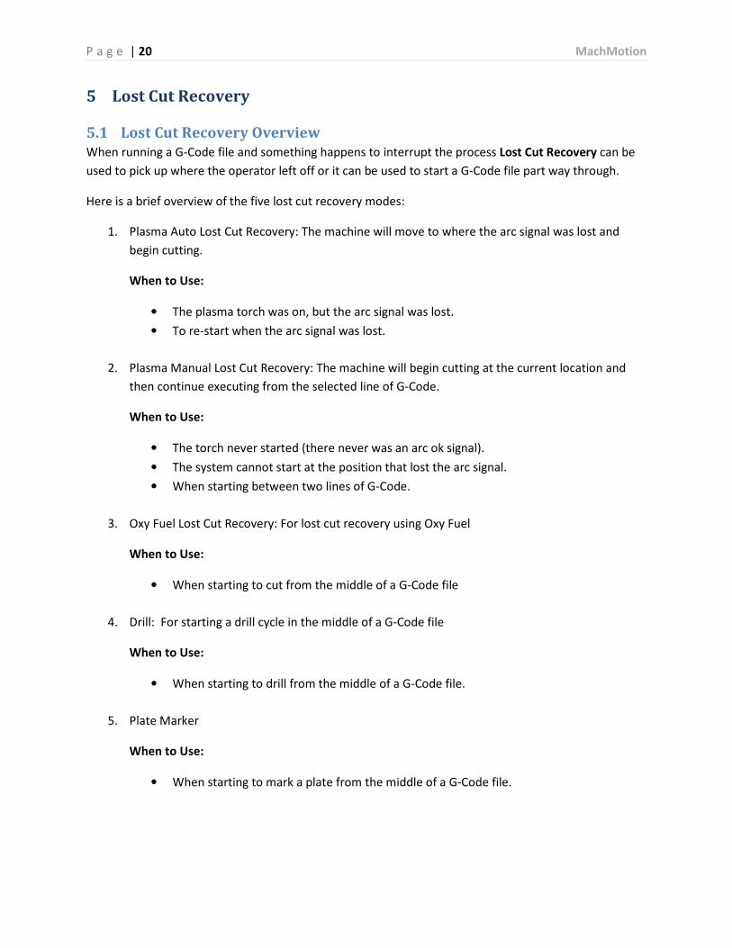
5.1 Lost Cut Recovery Overview
When running a G-Code file and something happens to interrupt the process Lost Cut Recovery can be
used to pick up where the operator left off or it can be used to start a G-Code file part way through.
Here is a brief overview of the five lost cut recovery modes:
1. Plasma Auto Lost Cut Recovery: The machine will move to where the arc signal was lost and
begin cutting.
When to Use:
• The plasma torch was on, but the arc signal was lost.
• To re-start when the arc signal was lost.
2. Plasma Manual Lost Cut Recovery: The machine will begin cutting at the current location and
then continue executing from the selected line of G-Code.
When to Use:
• The torch never started (there never was an arc ok signal).
• The system cannot start at the position that lost the arc signal.
• When starting between two lines of G-Code.
3. Oxy Fuel Lost Cut Recovery: For lost cut recovery using Oxy Fuel
When to Use:
• When starting to cut from the middle of a G-Code file
4. Drill: For starting a drill cycle in the middle of a G-Code file
When to Use:
• When starting to drill from the middle of a G-Code file.
5. Plate Marker
When to Use:
• When starting to mark a plate from the middle of a G-Code file.

P a g e | 21 MachMotion
5.2 Lost Cut Recovery Procedure
5.2.1 Plasma – Auto
The procedure for conducting a Plasma auto lost cut recovery is as follows:
1. To start Lost Cut Recovery press the Lost Cut Recovery button (See Figure 17).
2. Press the Plasma button under Auto Lost Cut Recovery causing the following dialog to appear
Figure 18 - Auto Plasma Lost Cut Recovery Dialog
3. Press Yes to continue with the current feed rate or No to set a new feed rate.
The machine will move to where the arc was lost, re-reference the Z axis, and then begin cutting. See
Figure 7.
WARNING: The machine will move to the last location where an arc signal was lost. Make sure that the
torch had been on. If not done properly, this mode could cause severe damage to the machine and/or
material.
5.2.2 Plasma – Manual
The procedure for conducting a Plasma manual lost cut recovery is as follows:
1. Scroll through the G-Code to select the line to begin cutting on.
2. Move the machine to the EXACT X and Y position where you want the machine to begin cutting
using the Forward and Backup buttons. The Forward and Backup buttons will move the
machine to the final commanded position of a G-Code line. See Figure 17.
Note: If you want to start in the middle of an arc or line segment you must turn Simulate on and
press Cycle Start. The machine will begin moving along the profile. Press Stop when the cutter
reaches the point that you want to begin cutting from.
3. Press the Lost Cut Recovery button. See Figure 17.

P a g e | 22 MachMotion
4. Press the Plasma button under Manual Lost Cut Recovery (See Figure 23) causing the following
dialog to appear
Figure 19 – Manual Plasma Lost Cut Recovery Dialog
Your machine will re-reference the Z axis, and then begin cutting from the current position. See Figure 7.
WARNING: Your machine will pierce and then start cutting at the current position.
5.2.3 Oxy Fuel
The procedure for conducting an Oxy Fuel lost cut recovery is as follows:
1. Scroll through the G-Code until you locate the line where you want your program to begin
cutting.
2. Move the machine to the EXACT X and Y position where you want the machine to begin cutting
using the Forward and Backup buttons. The Forward and Backup buttons will move the
machine to the final commanded position of a G-Code line. See Figure 17.
Note: If you want to start in the middle of an arc or line segment you must turn Simulate on and
press Cycle Start. The machine will begin moving along the profile. Press Stop when the cutter
reaches the point that you want to begin cutting from.
3. Press the Lost Cut Recovery button. See Figure 17.
4. Press the Oxy Fuel button under Manual Lost Cut Recovery (See Figure 23) causing the following
dialog to appear

P a g e | 23 MachMotion
Figure 20 - Oxy Fuel Lost Cut Recovery Dialog
Your machine will begin cutting from the current position. See Figure 11.
5.2.4 Drill
The procedure for conducting a Drill cycle is as follows starting from the middle of G-Code file:
1. Scroll through the G-Code until you locate the line where you want your program to begin
drilling.
2. Move the machine to the EXACT X and Y position where you want the machine to begin cutting
using the Forward and Backup buttons. The Forward and Backup buttons will move the
machine to the final commanded position of a G-Code line. See Figure 17.
3. Press the Lost Cut Recovery button. See Figure 17.
4. Press the Drill button under Manual Lost Cut Recovery (See Figure 23) causing the following
dialog to appear
Figure 21 - Drill Cycle Dialog
Note: Your machine will begin drilling from the current position.
5.2.5 Plate Marker
The procedure for conducting a Plate Marker cycle is as follows:

P a g e | 24 MachMotion
1. Scroll through the G-Code until you locate the line where you want your program to begin
marking the plate.
2. Move the machine to the EXACT X and Y position where you want the machine to begin marking
using the Forward and Backup buttons. The Forward and Backup buttons will move the
machine to the final commanded position of a G-Code line. See Figure 17.
Note: If you want to start in the middle of an arc or line segment you must turn Simulate on and
press Cycle Start. The machine will begin moving along the profile. Press Stop when the plate
marker reaches the point that you want to begin marking from.
3. Press the Lost Cut Recovery button. See Figure 17.
4. Press the Plate Marker button under Manual Lost Cut Recovery (See Figure 23) causing the
following dialog to appear
Figure 22 - Plate Marker Dialog
Note: Your machine will move the plate marker down to the material and begin marking from the
current position.
Figure 23 - Lost Cut Recovery Dialog

P a g e | 25 MachMotion
This page was intentionally left blank.

P a g e | 26 MachMotion
6 Appendix A – Button Definitions
6.1 Feed Rate
The window shows the current commanded feed rate. The feed rate can be overridden using the UP and
Down buttons to scale the feed rate from 0-300% of the commanded value. The Reset button returns
the override percentage back to 100%.
Figure 24 – Feed Rate Window
6.2 Load Location
The load location is an operator defined position for the cutting head to go to be out of the way for
material loading and unloading.
It will not interfere with homing or the part zero.
6.3 Max and Min THC
The min and max THC values are the allowable Z-Axis deltas from the position the torch is in when torch
turns on.
6.4 Pierce Reference Distance
Due to temperature fluctuations the material on a system often warps and bends. To compensate for
this and avoid crashes the controller needs to reference the material height. However, it is not
necessary to reference the material every time a new cut is made. Doing so can significantly slow down
production times. See Figure 25.
The pierce reference distance allows the operator to define a distance within which the controller will
not re-reference the material. So after it references for a cut any following cut within the pierce
reference distance from the first cut will not require a second reference.
6.5 Plate Height Offset
The Plate Height Offset is the travel distance between the floating head’s position at rest to the
reference switch. The distance as entered into Mach3 is always negative. See Figure 25.

P a g e | 27 MachMotion
6.6 Z Rapid Height
Between cuts the cutting head will go up to the defined Z rapid height during while moving from one cut
position to the next. Using a low rapid height in combination with a long pierce reference distance can
significantly speed up part cut times. This is especially the case for parts with lots of holes and small
cuts. See Figure 25.

P a g e | 28 MachMotion
7 Appendix B – Diagnostics
7.1 Tool Change Location
The tool change location is an operator defined location chosen to conveniently change tools.
7.2 Lost Arc Location
When the Arc OK signal is lost while cutting the location and G-Code line the cutter was on when it was
lost is recorded here.
Figure 25 - Diagnostics Screen
For Diagnostic and Tech Support Use

P a g e | 29 MachMotion
This page was intentionally left blank

P a g e | 30 MachMotion
8 Appendix C – MDI and Program Limits
8.1 Program Limits
The program limits show the axis limits of a G-Code file when one has been loaded.
8.2 MDI
The MDI line allows the operator to input G and M-Code commands manually.
Figure 26 – MDI Tab


![ก ˘ ˇ˘ˆ˙˝ ˛ Plasma cutting Torch height controlfile.siam2web.com/cnctak/files[document]/2012724_78232.pdf · Plasma cutting Torch height control Manufacturing BY:CNCtak .com](https://img.pdfslide.net/doc/110x75/5b970d2409d3f2e3488bd89b/-plasma-cutting-torch-height-document201272478232pdf.jpg)