Embed Size (px)
Citation preview

ARTICLE IN PRESS
Contents lists available at ScienceDirect
Journal of the Mechanics and Physics of Solids
Journal of the Mechanics and Physics of Solids ] (]]]]) ]]]–]]]
0022-50
doi:10.1
� Cor
Tel.: +1
E-m
Pleasdislo
journal homepage: www.elsevier.com/locate/jmps
Plasticity of metal wires in torsion: Molecular dynamics anddislocation dynamics simulations
Christopher R. Weinberger �, Wei Cai
Department of Mechanical Engineering, Stanford University, CA 94305-4040, USA
a r t i c l e i n f o
Article history:
Received 19 February 2010
Received in revised form
16 April 2010
Accepted 24 April 2010
Keywords:
Microstructures
Dislocations
Grain boundaries
96/$ - see front matter & 2010 Elsevier Ltd. A
016/j.jmps.2010.04.010
responding author. Current Address: Sandia N
505 284 0896.
ail addresses: [email protected] (C.R. Wein
e cite this article as: Weinberger,cation dynamics simulations. J. Mec
a b s t r a c t
The orientation dependent plasticity in metal nanowires is investigated using molecular
dynamics and dislocation dynamics simulations. Molecular dynamics simulations show
that the orientation of single crystal metal wires controls the mechanisms of plastic
deformation. For wires oriented along /1 1 0S, dislocations nucleate along the axis of
the wire, making the deformation homogeneous. These wires also maintain most of
their strength after yield. In contrast, wires oriented along /1 1 1S and /1 0 0Sdirections deform through the formation of twist boundaries and tend not to recover
when high angle twist boundaries are formed. The stability of the dislocation structures
observed in molecular dynamics simulations are investigated using analytical and
dislocation dynamics models.
& 2010 Elsevier Ltd. All rights reserved.
1. Introduction
The plastic response of materials at the small scale is an area of great interest because as sample dimensions decrease,the material’s mechanical response changes. The compression tests of micro- and nano-pillars has shown a dramaticincrease in flow stress as a function of material size (Uchic et al., 2004; Greer et al., 2005). In addition, strain bursts becomemore prominent in small scale structures (Dimiduk et al., 2006; Csikor et al., 2007; Brinckmann et al., 2008) which maylimit the ability of plastic metal-forming at the micro- and nano-scale (Csikor et al., 2007).
When materials are bent or twisted, they experience strain gradients which are known to alter the plastic response ofthe materials (Guzman et al., 1993; Fleck et al., 1994; Nix and Gao, 1998). This has lead to the development of straingradient plasticity, which explains strengthening of materials at small scale through the interaction of statistically storeddislocations and geometrically necessary dislocations (Fleck and Hutchinson, 1993, 1997). Strain gradient plasticity theoryhas been successful in explaining strengthening observed in polycrystalline wires under torsion (Fleck et al., 1994). Thisnaturally leads to the question of what happens when nanowires are twisted. Wires at this size are often single crystals,and there is very little experimental or numerical studies on plasticity of single crystal wires in torsion.
In this paper, we examine the plasticity of single crystal wires under torsion using both molecular dynamics (MD) anddislocation dynamics (DD) simulations. This will provide insight into how the deformation changes as a function of thewire’s diameter. Since the wires are single crystals, we will study three high symmetry directions, /1 1 0S, /1 1 1S and/1 0 0S. The authors have already presented a discussion on the mechanisms of yield in these wires (Weinberger and Cai,2010). In this work, we present a detailed look into the yield of the nanowires, boundary formation and stability.
ll rights reserved.
ational Laboratories, P.O. Box 5800, MS1411, Albuquerque, NM 87185-1411, USA.
berger), [email protected] (W. Cai).
C.R., Cai, W., Plasticity of metal wires in torsion: Molecular dynamics andh. Phys. Solids (2010), doi:10.1016/j.jmps.2010.04.010

ARTICLE IN PRESS
C.R. Weinberger, W. Cai / J. Mech. Phys. Solids ] (]]]]) ]]]–]]]2
Dislocation dynamics simulations will be presented in order to provide further understanding in the formation anddissolution of these structures.
2. Simulation methods
2.1. Molecular dynamics
To study the plasticity in metallic nanowires, the primary tool used here is molecular dynamics. To avoid end effects,torsional periodic boundary conditions (tPBC) are used in all of the simulations. The details of this method have beendescribed previously by the authors (Cai et al., 2008) including discussions on how to measure torque. The loading is anapplied affine twist enforced by the boundary conditions, the same way strain would be applied in MD simulations ofuniaxial loading of nanowires. This leads to a constant twist rate and hence a constant surface shear strain rate simulation.
In order to fully understand the plasticity in nanowires, a large number of parameters are varied as part of this study.The orientations of the nanowires studied are three high symmetry directions, /1 0 0S, /1 1 0S and /1 1 1S. Threediameters, 5, 7.5, and 10 nm, are used. The orientation and size of the nanowires are thought to provide the largest impacton plasticity in the nanowires. However, other effects will also be examined, including strain rates, aspect ratios, stackingfault energy, statistical variations, and surface defects.
The simulations are performed on two face-centered-cubic (FCC) metals, gold and aluminum, in order to capture theeffect of stacking fault energies. The interatomic potential for gold is the EAM Foiles (Park and Zimmerman, 2005), whichhas a stacking fault energy of 31 mJ/m2 and agrees very well with DFT calculations. The aluminum potential used is theEAM Mishin et al. (1999) with a stacking fault energy of 146 mJ/m2. Since the stacking fault energy of gold is about fivetimes smaller than aluminum, larger diameter gold wires are also investigated. The stacking fault energy is important forthese simulations because the diameter of the wires studied approaches the equilibrium separation width between partialdislocations, governed by the stacking fault energy.
In order to compare different diameter wires, the nominal engineering surface shear strain rate is 4�108 s�1 for all thesimulations. This is accomplished by applying an incremental twist per unit length every 5 ps using a time step of 1 fs. Wedefine the engineering shear strain rate as _g ¼ _br, where _b is the twist rate per unit length and r is the radius where thestrain is evaluated. The surface engineering shear strain rate is found by evaluating r at the nanowire radius. Sincethe aspect ratio is held constant for all wires 10 nm and smaller, _b and _gjr ¼ R are constants, where R is the radius of thenanowire. Thus the maximum applied twist is also a constant, at 0.8 radians or 461.
In preparation for twisting, the wires are relaxed and equilibrated at 300 K. First, the nanowires are created from a bulkconfiguration and relaxed using conjugate gradient relaxation in order to alleviate axial stresses due to surface effects.Then, the wires are equilibrated at 300 K for 100 ps using a Nose–Hoover thermostat and a Parrinello–Rahman barostat toeliminate stresses in the wire, reproducing a NsT ensemble. The equilibrium length of the nanowire is taken to be theaverage of the last half of the equilibration run.
The twisting simulations are then carried out using torsional periodic boundary conditions along the z-axis of the wire.In order to alleviate axial stress that develops during the simulation, caused by either elastic or plastic processes, the lengthof the wire is allowed to relax using the Parrinello–Rahman stress control (Parrinello and Rahman, 1981) in that direction.The twist is incremented, however, at fixed intervals simulating a constant twist rate experiment.
2.2. Dislocation dynamics
The dislocation dynamics simulations are performed using the ParaDiS code developed at Lawrence Livermore NationalLaboratory (Cai et al., 2004; Bulatov et al., 2004). The perfect dislocations are approximated as straight line segments. Inorder to simulate dislocation structures in a nanowire, the free surfaces must be accounted for. The authors use a modifiedversion of the ParaDiS code for this purpose (Weinberger and Cai, 2007; Weinberger et al., 2009) which accuratelycomputes the image stress and interactions with free surfaces.
The dislocation dynamics simulations are further modified to account for the applied torque. From elasticity theory, atorque applied to a circular shaft can be related to the shear stress as szy ¼ tr=J where t is the applied torque, r is radius ofthe point where the stress is evaluated and J¼ ðp=2ÞR4 is the polar moment of inertial of a circular shaft with radius R. Theadditional force on the dislocations can be evaluated by integrating over the segment lengths as discussed in Arsenlis et al.(2007). For simplicity, we use one point quadrature for evaluation of the nodal force contribution from the applied torque.
For simulations of dislocations in /1 1 0S oriented wires, a two-dimensional dislocation dynamics code is used. Theforces on the dislocations are computed by superimposing the fields of infinitely long screw dislocations in cylindersderived by Eshelby (1953) and Eshelby (1979). The contributions arise from forces due to the dislocations in an infinitemedium, image forces required to make the surfaces traction free, and image torque forces required to make the rod torquefree. Additional forces from an applied torque are also included. The dislocations are allowed to relax in the direction of thetotal Peach–Koehler forces.
Please cite this article as: Weinberger, C.R., Cai, W., Plasticity of metal wires in torsion: Molecular dynamics anddislocation dynamics simulations. J. Mech. Phys. Solids (2010), doi:10.1016/j.jmps.2010.04.010

ARTICLE IN PRESS
C.R. Weinberger, W. Cai / J. Mech. Phys. Solids ] (]]]]) ]]]–]]] 3
3. Results
Fig. 1 shows torque twist curves for both gold and aluminum nanowires for all three orientations. From these results wecan make a simple observation about strength. In general, aluminum is stronger than gold. This is in agreement with thedifference in unstable stacking fault energies between the gold and aluminum potentials, which are 120 mJ/m2 and 168 mJ/m2 respectively.
For small angles, the torque is approximately linear with the applied twist, as predicted by linear elasticity. Therelationship for isotropy is t¼ Jmb where t is the torque, J is the polar moment of inertia and b is the twist per unit length.This can be used to approximate the torque twist relationship in the anisotropic case if we replace the isotropic shearmodulus with the effective shear modulus of the plane in torsion. We computed the effective shear modulus by simplyaveraging over all the shear moduli on the plane under torsion. The resulting torque twist relationships are
t¼ 1
4ðC11�C12þ2C44ÞJb /1 1 0S
t¼ 1
3ðC11�C12þC44ÞJb /1 1 1S
t¼ C44Jb /1 0 0S
The theoretical torsional stiffness, defined as kt � @t=@b, is compared against simulation data in Tables 1–3. Theagreement for aluminum is generally good for all three directions, with an error around 10%. The agreement betweentheory and simulation is not that good for gold, with errors around 30%. This disagreement persists at 0 K, but disappears ifthe torsional stiffness is calculated without letting the atoms relax between subsequent twists. These expressions arederived assuming that the cross-sections remain planar and circular. However, the shear modulus varies throughout thecross-section due to elastic anisotropy. Hence, cross-sections may become non-planar or non-circular, leading todiscrepancies. This hypothesis is supported by agreement achieved when the wire is not allowed to relax which forces thecross-sections to remain planar and circular. Another source of error is the uncertainty in the calculation of the radius.However, we note that the effective stress strain curves shown in Figs. 2, 7, and 10(c), (d) collapse on one another in thelinear range suggesting a lack of radius dependence.
3.1. /1 1 0S Orientation
If we define a yield strain gY ¼ bY R at which the curve first unloads, then the yield strain appears size independent forwires oriented along /1 1 0S, as shown in Table 1. The average and standard deviation of the yield strain are taken fromeight different runs for each case reported. Fig. 2(a) and (b) shows three sample twisting and untwisting curves for bothmetals at a diameter of 5 nm. Fig. 2(c) and (d) show an effective shear stress–strain response of the material for the threedifferent diameters. The strain is the engineering surface shear strain and the effective stress is the torque divided by theradius cubed, which removes and dependence on the radius of the wire.
The strength of the materials is not the only aspect of the deformation that depends on the wire material. Figs. 3 and 4show the evolution of plastic deformation in /1 1 0S oriented nanowires. As discussed previously by the authors
Fig. 1. Torque–twist per unit length curves for three different orientation 5 nm diameter (a) aluminum and (b) gold nanowires.
Please cite this article as: Weinberger, C.R., Cai, W., Plasticity of metal wires in torsion: Molecular dynamics anddislocation dynamics simulations. J. Mech. Phys. Solids (2010), doi:10.1016/j.jmps.2010.04.010

ARTICLE IN PRESS
Table 1Yield strains and torsional stiffnesses for /1 1 0S oriented metallic nanowires.
Material Diameter (nm) gY kt (eV A) kt (theory)
Gold 5 0.06170.002 (6.7570.25)�104 1.02 �105
Gold 7.5 0.05670.001 (3.4170.04) �105 5.19 �105
Gold 10 0.05770.002 (1.0870.004) �106 1.64 �106
Aluminum 5 0.08570.002 (1.0270.004) �105 1.10 �105
Aluminum 7.5 0.07870.002 (5.2470.02) �105 5.56 �105
Aluminum 10 0.07870.001 (1.6570.003) �106 1.77 �106
The yield strain gY ¼ bY R is calculated when the torque initially begins to unload. The torsional stiffness is kt ¼@t@b
and the averages and standard
deviations are reported for 8 different runs.
Table 2Yield strains and torsional stiffnesses for /1 1 1S oriented metallic nanowires.
Material Diameter (nm) gY kt (eV A) kt (theory)
Gold 5 0.09370.003 (6.1970.05)�104 8.68�104
Gold 7.5 0.08570.001 (2.9570.03)�105 4.40�105
Gold 10 0.08270.002 (9.7970.09)�105 1.39�106
Aluminum 5 0.11970.003 (9.0670.05)�104 1.07�105
Aluminum 7.5 0.10570.002 (4.8370.01)�105 5.41�105
Aluminum 10 0.09770.003 (1.5370.003)�106 1.71�106
Table 3Yield strains and torsional stiffnesses for /1 0 0S oriented metallic nanowires.
Material Diameter (nm) gY kt (eV A) kt (theory)
Gold 5 0.08270.005 (1.3870.004)�105 1.49�105
Gold 7.5 0.08070.002 (6.6270.02)�105 7.56�105
Gold 10 0.07470.002 (2.1170.004)�106 2.39�106
Aluminum 5 0.11370.003 (1.3970.003)�105 1.21�105
Aluminum 7.5 0.11270.003 (7.0270.02)�105 6.13�105
Aluminum 10 0.11270.006 (2.1470.002)�106 1.94�106
C.R. Weinberger, W. Cai / J. Mech. Phys. Solids ] (]]]]) ]]]–]]]4
(Weinberger and Cai, 2010), the gold nanowires deform mainly by nucleation of partial dislocations with the stackingfaults terminating at the wire surface. In contrast, the aluminum wires start by nucleating partial dislocations, but thetrailing partials follow creating perfect screw dislocations in the wire. For 5 nm diameter aluminum wires and 20 nmdiameter gold nanowires, we see a mixture of both partial and perfect dislocations. The difference in nucleating perfect andpartial dislocations is related to the material’s stacking fault energy and the radius of the nanowire. The stacking faultenergy of the gold potential is 31 and 146 mJ/m2 for the aluminum potential. This results in a equilibrium partialdislocation separation of approximately 1.5 and 0.3 nm in bulk gold and aluminum, respectively.
The nucleation of dislocations generally occur, in these simulations, on planes of maximum shear stress. A simpleconsideration of the torsion of a circular cross-section shows that two types of planes contain the maximum shear stress.Planes perpendicular to the wire axis are planes of maximum stress as well as all planes that contain the wire axis. In thecase of a /1 1 0S oriented nanowire, two {1 1 1} type planes contain the specific /1 1 0S direction, separated by 711, andare likely planes for dislocation activity. This is confirmed by examination of the planes of slip in Fig. 3.
The twisting and untwisting curves for gold in Fig. 2(b) show a large amount of, and often complete, reversibility duringuntwisting. Since the torque in the untwisting curves of gold generally do not drop below zero, this means that the dislocationsall leave prior to unloading. The torque, in a few cases, does drop below zero, but it is difficult to determine if this is causedsimply by fluctuations in the torque calculation, or a real unloading. Regardless, in every case the gold wires are always able torecover a significant amount of the deformation. For the case of aluminum, Fig. 2(a), we can see that the deformation is alwaysirreversible. If one wishes to remove all the dislocations from the wire, a negative torque must be applied to the wire in order toaccomplish this. The reversibility of the gold nanowires should be size dependent, though. As we will see later, perfectdislocations are generally stable inside a wire, making the deformation generally irreversible. As the wire diameter increasesthe amount of perfect dislocations that nucleate will increase, transitioning from reversible to irreversible deformation.
3.1.1. Stability analysis
The difference between perfect and partial dislocations in gold and aluminum illustrates that nucleation should dependon the stacking fault energy of the material and the diameter of the nanowire. This suggests that the difference in
Please cite this article as: Weinberger, C.R., Cai, W., Plasticity of metal wires in torsion: Molecular dynamics anddislocation dynamics simulations. J. Mech. Phys. Solids (2010), doi:10.1016/j.jmps.2010.04.010

ARTICLE IN PRESS
Fig. 2. Three representative torque twist curves showing both loading and unloading, (a) aluminum and (b) gold nanowires with 5 nm diameters.
Torsional stress–strain curves (c) for aluminum and (d) for gold, which illustrate the effect of diameter on mechanical properties.
71
Fig. 3. The evolution of dislocation networks in /1 1 0S gold nanowires. (a) The initial plastic event, (b) more partial dislocations nucleate and
(c) significant dislocation structure once loading is complete for a 7.5 nm diameter wire. (d) A similar network in a 20 nm diameter wire showing mostly
partial dislocations with a few perfect dislocations. The engineering surface shear strains for the configurations are: (a) 0.062, (b) 0.084, (c) 0.200, and
(d) 0.192.
Please cite this article as: Weinberger, C.R., Cai, W., Plasticity of metal wires in torsion: Molecular dynamics anddislocation dynamics simulations. J. Mech. Phys. Solids (2010), doi:10.1016/j.jmps.2010.04.010
C.R. Weinberger, W. Cai / J. Mech. Phys. Solids ] (]]]]) ]]]–]]] 5

ARTICLE IN PRESS
Fig. 4. The evolution of a dislocation network in a /1 1 0S aluminum nanowire. (a) Perfect and partial dislocations, (b) nucleated perfect dislocations and
(c) the final configuration. The engineering surface shear strains for the configurations are: (a) 0.108 (b) 0.118, and (c) 0.200.
−50 0 50−12
−10
−8
−6
−4
−2
0
2
4
6
8 x 10⁻³
f x (eV
/Å2 )
Dislocation position ξ (Å)
T = 0 eVT=607.4 eVT=1200 eV
ξ
1x
y
ξ
12 x
y
η
Fig. 5. The configuration for (a) two partial dislocations and (b) one partial dislocation in a cylinder and (c) the forces on one dislocation in a cylinder.
Unstable equilibrium points are marked with a circle and stable equilibrium points are marked with a square.
C.R. Weinberger, W. Cai / J. Mech. Phys. Solids ] (]]]]) ]]]–]]]6
nucleation may be explained purely through elastic effects and, that at some critical diameter, the dislocations are nolonger stable in the nanowire. A simple analytical model can be constructed involving two partial dislocations in a cylinderseparated by a stacking fault, as shown in Fig. 5(a). The forces on the dislocations and their stability can be written usingthe expressions developed by Eshelby (1979) as discussed in Appendix A. From this analysis we find that the partial pair isonly stable when their center of mass is at the center of the nanowire. A positive applied torque simply pushes the partialscloser together and enhances the stability of the configuration. Two negative critical torques can be established. One pullsthe partials out leaving a stacking fault. The other makes the configuration unstable with respect to perturbations of thecenter of mass, resulting in the partial pair leaving together. The lower critical torque, from numerical investigations,appears to always be the center of mass instability. This makes sense since the wire containing a stacking fault will have ahigher energy than the defect free wire.
This problem is very similar to the problem Eshelby (1953) solved which showed that perfect screw dislocations arestable inside whiskers. However, we now have two partial dislocations bounded by a stacking fault inside a cylinder. Forthe perfect screw dislocation problem, Eshelby was able to show that an applied torque drives the screw dislocation outwhen it reaches a critical value of t¼� 1
4mbR2. We can compare this to our solution for a screw dislocation dipole in goldwith m¼ 31 GPa, n¼ 0:4, b¼ 2:88 A, be ¼ 0:83 A, bs ¼ 1:44 A, g¼ 30 mJ=m2 and the radius is taken to be R=25 A. The criticaltorque predicted by our analysis is tcrit ¼�53:6 eV while Eshelby’s result gives tcrit ¼�87:2 eV. This shows that thedissociated dislocation is less stable than a non-dissociated perfect dislocation. This can be compared with the criticaltorque to pull two partial dislocations out of the wire in opposite directions, �169 eV, whose magnitude is much higher.As the diameter of the wire increases, the critical torque approaches that predicted by Eshelby; at a radius of 50 A we findthe critical torques are �306 eV and �349 eV for this analysis and Eshelby’s, respectively. This shows that the partialdislocation pairs behave as perfect dislocations for all but the smallest nanowires.
The above model is unable to explain why at smaller diameters only partial dislocations nucleate because it predictsthat a partial dislocation pair is also (meta-)stable in torque free nanowires. However, elasticity models can help explainwhy the deformation in gold nanowires is reversible but not is in aluminum. This is because a pair of partial dislocations
Please cite this article as: Weinberger, C.R., Cai, W., Plasticity of metal wires in torsion: Molecular dynamics anddislocation dynamics simulations. J. Mech. Phys. Solids (2010), doi:10.1016/j.jmps.2010.04.010

ARTICLE IN PRESS
Fig. 6. The equilibrium structure of (a) 4, (b) 8, and (c) 20 dislocations in a torque free cylinder and (d) 20 dislocations under an applied torque. The
patterning of these dislocations illustrates the homogeneity of the deformation.
C.R. Weinberger, W. Cai / J. Mech. Phys. Solids ] (]]]]) ]]]–]]] 7
(connected by a stacking fault) is meta-stable in the torque-free wire while a single partial dislocation is not. The force on asingle partial dislocation shown in Fig. 5(b) is
f 1x ¼
mb2e
2pð1�nÞx
R2�x2þmb2
s
2px
ðR2�x2Þ�
2xðR2�x2Þ
R4
" #�g� 2
pxR4
bst ð1Þ
and is plotted in Fig. 5(c). For zero torque, the partial dislocation has one equilibrium position for which x40. This positionis an unstable equilibrium since the slope at the point is positive, which results in a negative second derivative of theenergy. It is possible, just as it was for the pair of partials, to determine the torque required to make the dislocation stableusing similar criterion. The dislocation is stable when fx
1=0 and @f 1x =@xo0. The critical torque can be found by requiring
fx1=0 and @f 1
x =@x¼ 0. The critical torque to stabilize the partial dislocation is now positive and has a value of 607 eV. Thisshows that a single partial dislocation is unstable in a torque free wire. Therefore, when the wire is unloaded in our MDsimulations, perfect dislocations already in the wire remain and provide a plastic twist. However, if only the leading partialdislocations nucleate, they are unstable and will leave during the unloading process, creating a reversible torque twistcurve.
3.1.2. Dislocation patterning
The deformation shown in Fig. 4 and discussed previously shows striking homogeneity. This has important implicationsfor plastic metal forming at the micro and nanoscales. To better understand this process, we need to predict how moredislocations will distribute in the wire during deformation. This can be done using a two dimensional dislocation dynamicscode as described previously. In this model, every dislocation will be modeled as a like signed perfect screw dislocationand will be initially placed in the cylinder at a random location within 0.5 of the radius (so that they do not escape). Theresulting equilibrium configurations are shown in Fig. 6. A simple ring structure appears stable when the number ofdislocations is about 6 or less. When there are 6 or more dislocations, one dislocation will occupy the center position.A large number of dislocations shows more complicated ring structures, as in Fig. 6(c). Barnett and Nix (Private commu-nication) have shown that a ring of N dislocations is always in equilibrium in a torque-free cylinder. When our DDsimulations are carried out, the ring structure appears to be an unstable equilibrium for N greater than 6 and numericalnoise changes the structure to one or more dislocations inside the outer ring. This patterning shows that as more dis-locations are nucleated, they spread out ensuring the deformation continues in a homogeneous fashion.
The patterning shown in Fig. 6 results from allowing the dislocations to move along the direction of the Peach–Koehlerforce. As shown in our MD simulations, the dislocations appear confined to slip planes and may not be able to reach theseequilibrium positions. That may influence the resulting patterning seen in MD simulations and what would be observed inexperiments. Furthermore, the application of torque tends to drive the dislocations into the interior of the wire, as shownin Fig. 6(d). Therefore, the completely disperse configuration shown in Fig. 6(c) should not always be expected. Finally,these simulations show that an arbitrarily large number of screw dislocations can be in equilibrium in a torque free wire.
3.2. /1 1 1S Orientation
For a /1 1 1S- oriented wire a {1 1 1} type plane is oriented perpendicular to the wire axis, which as discussed before, isa plane of maximum stress. This suggests that this plane will be the most active slip plane during plastic deformation. Forthese nanowires, the trend shown in Table 2 is that smaller is stronger. The stress required for nucleation decreases as afunction of the wire diameter. We also see that aluminum is again stronger than gold in this orientation.
Fig. 7 shows the twisting and un-twisting curves for the /1 1 1S oriented nanowires in addition to the normalizedstress–strain curves. The un-twisting part of the curves show that the deformation is essentially irreversible. These figuresalso illustrate an important difference between the gold and aluminum torque twist curves. When the aluminum wiresyield, the torque relaxes to nearly zero almost instantaneously. Gold, however, unloads more slowly reaching a near zerotorque condition close to the end of the simulations. This behavior correlates well with the dislocation network formation.When aluminum wires yield, the dislocations nucleate and organize into structures while the torque drops. By the time thetorque is completely relaxed, a high angle twist boundary has already formed. However, in gold, the dislocation structures
Please cite this article as: Weinberger, C.R., Cai, W., Plasticity of metal wires in torsion: Molecular dynamics anddislocation dynamics simulations. J. Mech. Phys. Solids (2010), doi:10.1016/j.jmps.2010.04.010

ARTICLE IN PRESS
Fig. 7. Three representative torque twist curves showing both loading and unloading for /1 1 1S oriented (a) aluminum and (b) gold nanowires.
Torsional stress–strain curves (c) for aluminum and (d) for gold, which illustrate the effect of diameter on mechanical properties.
C.R. Weinberger, W. Cai / J. Mech. Phys. Solids ] (]]]]) ]]]–]]]8
take longer to nucleate and organize, so the torque stays higher for much longer. This can be attributed to the higher torquewhen dislocations first nucleate in aluminum compared to gold.
3.2.1. Dislocation patterning
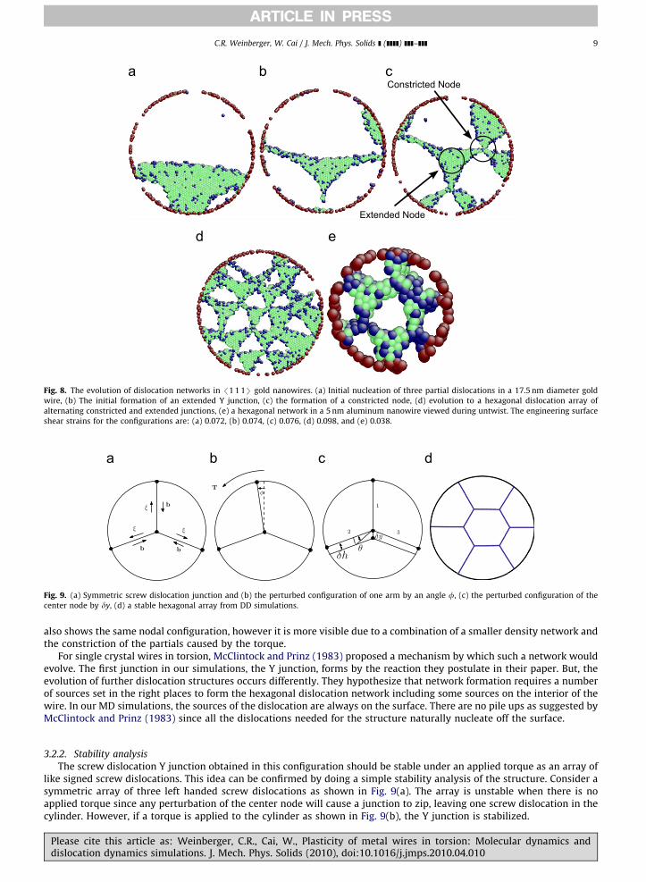
The strength of the wires may depend weakly on the diameter, however we do not see a great difference in the behaviorof the dislocations that emerge from the deformation. The deformation is limited to one or just a few planes, localizing thedeformation. The dislocation structure that evolves initially starts by the creation of a Y junction shown in Fig. 8(a) and (b).The junction starts from the nucleation of a single partial dislocation. As the partial dislocation expands, it eventuallynucleates two trailing partial dislocations, which covers all three possible partial dislocations on that glide plane. Thisstructure, as seen in Fig. 8(b), is all that is needed to evolve into a extended Y junction. Fig. 8(b) and (c) also shows thatconstricted Y junctions can form from the interaction of two dislocations. Our simulations show that both constricted andextended nodes can form as the initial embryo of the twist boundary. However, a Y junction of screw dislocations is thefirst step in the twist boundary formation.
As the dislocation structure evolves, it develops into a {1 1 1} twist boundary shown in Fig. 8(d). The clarity of this figureis unique since in most our simulations partial dislocations nucleated on parallel planes close to the twist boundary restrictvisualization. The larger diameter wires, such as the 17.5 nm in diameter shown, illustrate the difference betweenconstricted and extended nodes better. But, this also makes visualization of the hexagonal structure more difficult. Fig. 8(d)shows a hexagonal structure during untwisting in a 5 nm diameter aluminum wire. Careful examination of this network
Please cite this article as: Weinberger, C.R., Cai, W., Plasticity of metal wires in torsion: Molecular dynamics anddislocation dynamics simulations. J. Mech. Phys. Solids (2010), doi:10.1016/j.jmps.2010.04.010
ARTICLE IN PRESS
Constricted Node
Extended Node
Fig. 8. The evolution of dislocation networks in /1 1 1S gold nanowires. (a) Initial nucleation of three partial dislocations in a 17.5 nm diameter gold
wire, (b) The initial formation of an extended Y junction, (c) the formation of a constricted node, (d) evolution to a hexagonal dislocation array of
alternating constricted and extended junctions, (e) a hexagonal network in a 5 nm aluminum nanowire viewed during untwist. The engineering surface
shear strains for the configurations are: (a) 0.072, (b) 0.074, (c) 0.076, (d) 0.098, and (e) 0.038.
Fig. 9. (a) Symmetric screw dislocation junction and (b) the perturbed configuration of one arm by an angle f, (c) the perturbed configuration of the
center node by dy, (d) a stable hexagonal array from DD simulations.
C.R. Weinberger, W. Cai / J. Mech. Phys. Solids ] (]]]]) ]]]–]]] 9
also shows the same nodal configuration, however it is more visible due to a combination of a smaller density network andthe constriction of the partials caused by the torque.
For single crystal wires in torsion, McClintock and Prinz (1983) proposed a mechanism by which such a network wouldevolve. The first junction in our simulations, the Y junction, forms by the reaction they postulate in their paper. But, theevolution of further dislocation structures occurs differently. They hypothesize that network formation requires a numberof sources set in the right places to form the hexagonal dislocation network including some sources on the interior of thewire. In our MD simulations, the sources of the dislocation are always on the surface. There are no pile ups as suggested byMcClintock and Prinz (1983) since all the dislocations needed for the structure naturally nucleate off the surface.
3.2.2. Stability analysis
The screw dislocation Y junction obtained in this configuration should be stable under an applied torque as an array oflike signed screw dislocations. This idea can be confirmed by doing a simple stability analysis of the structure. Consider asymmetric array of three left handed screw dislocations as shown in Fig. 9(a). The array is unstable when there is noapplied torque since any perturbation of the center node will cause a junction to zip, leaving one screw dislocation in thecylinder. However, if a torque is applied to the cylinder as shown in Fig. 9(b), the Y junction is stabilized.
Please cite this article as: Weinberger, C.R., Cai, W., Plasticity of metal wires in torsion: Molecular dynamics anddislocation dynamics simulations. J. Mech. Phys. Solids (2010), doi:10.1016/j.jmps.2010.04.010

ARTICLE IN PRESS
C.R. Weinberger, W. Cai / J. Mech. Phys. Solids ] (]]]]) ]]]–]]]10
In order to understand how the dislocation structure is stabilized we analyze a perturbed state shown in Fig. 9(b). ThePeach–Koehler force exerted on the vertical segment as it is displaced from the screw orientation by an angle f is
f ¼�tbr
Jðsinfcosfxþsin2fyÞ ð2Þ
where b is the magnitude of the Burgers vector, t is the applied torque, J is the polar moment of inertia and r is the radialdistance. For f51, this reduces to
f ¼�tbr
Jfx ð3Þ
which is a restoring force opposite to the direction of f. Of course, if the array were composed of right handed screwdislocations instead, then bo0 and the force is destabilizing. The force would also be destabilizing for a left handed screwarray with a negative applied torque.
The perturbation of one of the arms by an angle f illustrates the stabilizing nature of the applied torque. However, thedislocation arm would also tend to rotate back by a line tension argument. This is because the rotated arm has a higherenergy since it has an edge component. In addition, the previous analysis does not predict a critical torque to stabilize thejunction. This can be done by considering another perturbed configuration shown in Fig. 9(c) where the center node ismoved by a distance dy without changing the arm angles. To first order in dy, the line length of the junction does notchange. The work done by the applied torque is zero to first order, which is the Peach–Koehler force on the unperturbedconfiguration. Therefore, to investigate the critical torque, the configuration must be analyzed to second order in dy, whichis done in detail in Appendix B. The critical torque is
tc ¼R2mb
8log
R
b
� �ð4Þ
A hexagonal network, like the one shown in Fig. 9(d), will have a critical torque as well. This is the torque required tokeep the hexagonal structure inside the wire diameter. Lowering the torque would allow the structure to dissolve, whileincreasing it will simply create a more compact hexagon. If we approach the problem using line tension arguments asabove, we find that the change in energy is zero. This is because as the hexagon enlarges, the change in perimeter alwaysexactly matches the loss of length in the spokes. However, if we account for the elastic interactions, the structure would beunstable at zero torque due to the repulsion of the like-signed screw dislocations. The repulsive Peach–Koehler force can beapproximated by assuming the screw segments in the hexagon interact as straight infinite segments with a forcef ¼ mb2=4pr where r is half the distance between them. The applied torque provides a stabilizing force of f ¼�trb=J.Equating forces and solving for the torque gives t¼ mJb=4pr2. From this simple model we estimate the critical torque interms of R by setting r=R and assuming a simple constant of proportionality
tc ¼ amJb
4pR2¼ ambR2
8
The critical torque for the hexagonal loop is very similar in form to that of the Y junction. One could also propose such aform based on dimensional analysis since the torque must be proportional to the shear modulus times the Burgers vectorand the R2 term comes from the only available length scale parameter in the problem.
The stability of these structures is further confirmed using dislocation dynamics. The screw dislocation array shown inFig. 9(a) is a stable equilibrium structure in DD under an appropriate applied torque. A Y junction is created and the centernode is moved down as part of the initial structure. Reversing the direction of the torque causes the structure to dissolve, inagreement with the above calculations. Fig. 9(d) shows a hexagonal structure in dislocation dynamics, which is alsostabilized by an applied torque. In our dislocation dynamics simulations, the hexagonal array dissolves when the appliedtorque is removed. We note that in a real crystal, the twist boundary may be stabilized (even at zero applied torque) byimpurities or other defects.
3.3. /1 0 0S Orientation
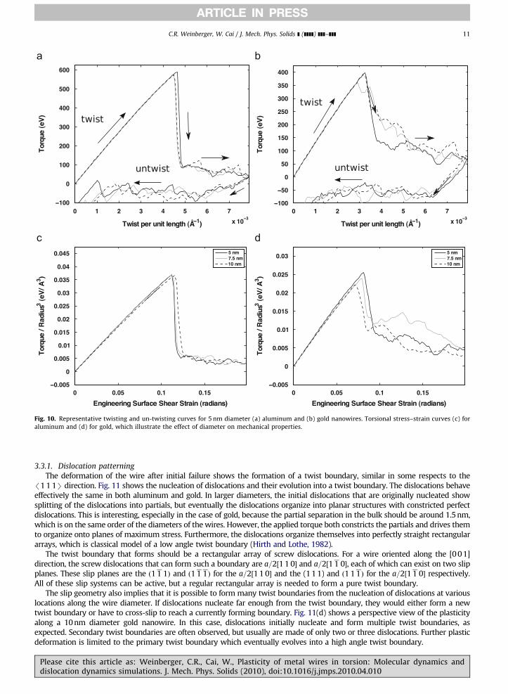
The /1 0 0S is a high symmetry direction and has been the subject of intensive investigations of size effects inmicropillars. The orientation is the highest symmetry direction in uniaxial loading involving the most possible slipsystems. However, we note that based on a qualitative look at the associated stress strain curves, it appears similar to the/1 1 1S direction. Fig. 10(a) and (b) shows the torque twist curves for both aluminum and gold for 5 nm diameter wiresand we note a similar significant drop in the torque upon dislocation nucleation. However, it is not clear if there is a trendto the strength of the nanowires as a function of diameter, as illustrated in Fig. 10(c) and (d). The yield strain of the wiresfrom Table 3 shows a slight decrease in strength for gold, but not as strong or obvious as the /1 1 1S direction. Thestrength of the wires for aluminum remains constant, independent of diameter.
Please cite this article as: Weinberger, C.R., Cai, W., Plasticity of metal wires in torsion: Molecular dynamics anddislocation dynamics simulations. J. Mech. Phys. Solids (2010), doi:10.1016/j.jmps.2010.04.010
ARTICLE IN PRESS
Fig. 10. Representative twisting and un-twisting curves for 5 nm diameter (a) aluminum and (b) gold nanowires. Torsional stress–strain curves (c) for
aluminum and (d) for gold, which illustrate the effect of diameter on mechanical properties.
C.R. Weinberger, W. Cai / J. Mech. Phys. Solids ] (]]]]) ]]]–]]] 11
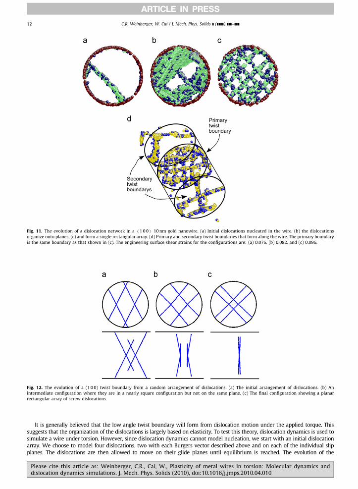
3.3.1. Dislocation patterning
The deformation of the wire after initial failure shows the formation of a twist boundary, similar in some respects to the/1 1 1S direction. Fig. 11 shows the nucleation of dislocations and their evolution into a twist boundary. The dislocations behaveeffectively the same in both aluminum and gold. In larger diameters, the initial dislocations that are originally nucleated showsplitting of the dislocations into partials, but eventually the dislocations organize into planar structures with constricted perfectdislocations. This is interesting, especially in the case of gold, because the partial separation in the bulk should be around 1.5 nm,which is on the same order of the diameters of the wires. However, the applied torque both constricts the partials and drives themto organize onto planes of maximum stress. Furthermore, the dislocations organize themselves into perfectly straight rectangulararrays, which is classical model of a low angle twist boundary (Hirth and Lothe, 1982).
The twist boundary that forms should be a rectangular array of screw dislocations. For a wire oriented along the [0 0 1]direction, the screw dislocations that can form such a boundary are a=2½1 1 0� and a=2½1 1 0�, each of which can exist on two slipplanes. These slip planes are the ð1 1 1Þ and ð1 1 1Þ for the a=2½1 1 0� and the (1 1 1) and ð1 1 1Þ for the a=2½1 1 0� respectively.All of these slip systems can be active, but a regular rectangular array is needed to form a pure twist boundary.
The slip geometry also implies that it is possible to form many twist boundaries from the nucleation of dislocations at variouslocations along the wire diameter. If dislocations nucleate far enough from the twist boundary, they would either form a newtwist boundary or have to cross-slip to reach a currently forming boundary. Fig. 11(d) shows a perspective view of the plasticityalong a 10 nm diameter gold nanowire. In this case, dislocations initially nucleate and form multiple twist boundaries, asexpected. Secondary twist boundaries are often observed, but usually are made of only two or three dislocations. Further plasticdeformation is limited to the primary twist boundary which eventually evolves into a high angle twist boundary.
Please cite this article as: Weinberger, C.R., Cai, W., Plasticity of metal wires in torsion: Molecular dynamics anddislocation dynamics simulations. J. Mech. Phys. Solids (2010), doi:10.1016/j.jmps.2010.04.010
ARTICLE IN PRESS
Fig. 11. The evolution of a dislocation network in a /1 0 0S 10 nm gold nanowire. (a) Initial dislocations nucleated in the wire, (b) the dislocations
organize onto planes, (c) and form a single rectangular array. (d) Primary and secondary twist boundaries that form along the wire. The primary boundary
is the same boundary as that shown in (c). The engineering surface shear strains for the configurations are: (a) 0.076, (b) 0.082, and (c) 0.096.
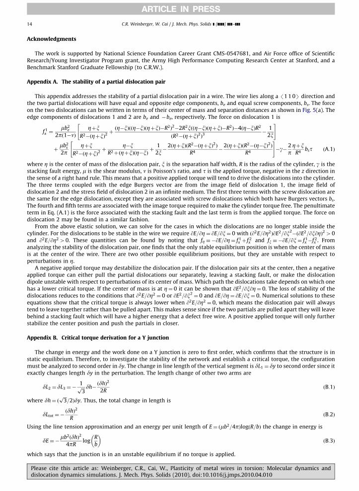
Fig. 12. The evolution of a (1 0 0) twist boundary from a random arrangement of dislocations. (a) The initial arrangement of dislocations. (b) An
intermediate configuration where they are in a nearly square configuration but not on the same plane. (c) The final configuration showing a planar
rectangular array of screw dislocations.
C.R. Weinberger, W. Cai / J. Mech. Phys. Solids ] (]]]]) ]]]–]]]12
It is generally believed that the low angle twist boundary will form from dislocation motion under the applied torque. Thissuggests that the organization of the dislocations is largely based on elasticity. To test this theory, dislocation dynamics is used tosimulate a wire under torsion. However, since dislocation dynamics cannot model nucleation, we start with an initial dislocationarray. We choose to model four dislocations, two with each Burgers vector described above and on each of the individual slipplanes. The dislocations are then allowed to move on their glide planes until equilibrium is reached. The evolution of the
Please cite this article as: Weinberger, C.R., Cai, W., Plasticity of metal wires in torsion: Molecular dynamics anddislocation dynamics simulations. J. Mech. Phys. Solids (2010), doi:10.1016/j.jmps.2010.04.010

ARTICLE IN PRESS
C.R. Weinberger, W. Cai / J. Mech. Phys. Solids ] (]]]]) ]]]–]]] 13
dislocation structure is shown in Fig. 12. The simulations shows that under an applied torque, the dislocations rotate to screworientation, form a grid, and eventually move onto the same plane, perpendicular to the wire axis.
4. Discussion
The issue of strain rate is always important in MD simulations since high strain rates ð � 108 s�1Þ cannot be avoided.Certainly the strain rate will affect the strain at which the dislocation nucleate (Zhu et al., 2008). However, the moreimportant question is whether the high strain rate changes the deformation mechanism. To address this question, we havefirst carried out simulations with the number of time steps increased from 5000 to 25 000 for 5 nm diameter goldnanowires. This drops the strain rate from nominally 4� 108 to 8� 107 and there are no changes in deformationmechanisms. Of course, a brute force approach is limited by computer resources. That is why it is important to note thatthe mechanisms by which the structures dissolve are the same when they form. During the dissolution, the applied torqueis usually much lower than when the dislocations originally nucleate, showing that their occurrence is not due to the highstresses. Furthermore, dislocation dynamics simulations also support the structures that form and are in agreement withclassical models. This suggests that our results are not strongly dependent on the applied strain rate.
The results presented here are for pristine wires without surface or other defects. A question that arises is how surfacedefects affect the homogeneity of the deformation. We expect that defects will cause the deformation to be come moreheterogeneous, localized around the defect. To address this we have also carried out simulations of 5 nm diameter goldnanowires with surface vacancies where 6 atom clusters were removed on the wire surface. The results show that thevacancy clusters are where dislocations originally nucleate, as commonly expected. However, since the /1 1 1S and/1 0 0S oriented nanowires already show heterogeneous deformation, it does not change the deformation mechanisms.For the /1 1 0S orientations, the dislocations start to nucleate at the vacancies, but also nucleate at other sites later in thedeformation. Even if a vacancy was a continued site for nucleation for perfect dislocations, it would still likely result inhomogeneous deformation since the nucleated dislocations would spread out in the interior, as illustrated in our DDsimulations. Thus, while surface defects can act as preferential sites for nucleation, they do not tend to alter the plasticdeformation that occurs.
Even though the wires are under (torsional) periodic boundary conditions along their length, the question of lengthdoes arise. In our simulations the length of the wire was twice the diameter, or an aspect ratio of two. Simulations werealso carried out for wires that are twice as long, for aspect ratios of 4. These simulations also show no change in themechanisms of plastic deformation. The deformation for the /1 1 0S and /1 1 1S are essentially limited to a plane, so thelength would appear to have little effect. For the /1 0 0S, we may expect to see a few more dislocations along its length ifinitial nucleation does not occur near a single boundary. However, after a boundary forms, further deformation occurs onlyon this boundary regardless of length.
These simulations show that wires under torsion can deform either through the formation of twist boundaries, asexpected, or through coaxial or Eshelby dislocations. When the deformation is through coaxial dislocations, thedeformation is homogeneous and potentially reversible if the wires are small enough to nucleate only partial dislocations.Furthermore, /1 1 0S wires deform in such a way that they maintain a significant fraction of their strength while in otherdirections there is a significant strength loss.
This orientation dependent plasticity under strain gradients has important implications for strain gradient theories. Thiswork suggests that different dislocation networks can form, with different densities, that all accomodate the plastic twistbut depend only on wire orientation. Orientation dependent strain gradient plasticity models, as suggested by theseresults, may overcome some of the limitations of existing theories (Kubin, 2003).
There is no reason to expect that these results, except for reversibility, should be limited to nanowires. Since themechanisms do not appear to be size dependent, we expect the results to be applicable to single crystal microwires as well,as long as the wires are initially dislocation free. The existence of initial dislocation networks may alter how the wiresdeform, since networks will likely evolve out of the multiplication of the statistically stored dislocations inside the wires.Dislocation dynamics simulations can help answer these questions in the future.
5. Conclusion
We have shown that the plasticity of pristine single crystal FCC metallic wires in torsion is orientation dependent. Forwires oriented along the /1 1 0S, coaxial dislocation nucleate causing the plasticity to be homogeneous. For the /1 1 1Sand /1 0 0S orientations, twist boundaries form which localizes the deformation. The /1 1 0S wires also maintain asignificant fraction of their strength after yield, while the other directions lose most of their strength.
When /1 1 0S wires are small enough, only partial dislocations nucleate and the deformation becomes reversible sincepartial dislocations are unstable in torque free wires. For thick /1 1 0S wires, perfect dislocations nucleate and our DDsimulations show that many screw dislocations can co-exist in the wire even in a torque-free state. For /1 1 1S wires, thehexagonal dislocation network that forms the twist boundary is stable in the wire only when the applied torque exceeds acritical value. Finally, DD simulations show that rectangular dislocation networks in /1 0 0S wires can be formed byrotation of existing dislocations under the inhomogeneous stress field from the applied torque.
Please cite this article as: Weinberger, C.R., Cai, W., Plasticity of metal wires in torsion: Molecular dynamics anddislocation dynamics simulations. J. Mech. Phys. Solids (2010), doi:10.1016/j.jmps.2010.04.010
ARTICLE IN PRESS
C.R. Weinberger, W. Cai / J. Mech. Phys. Solids ] (]]]]) ]]]–]]]14
Acknowledgments
The work is supported by National Science Foundation Career Grant CMS-0547681, and Air Force office of ScientificResearch/Young Investigator Program grant, the Army High Performance Computing Research Center at Stanford, and aBenchmark Stanford Graduate Fellowship (to C.R.W.).
Appendix A. The stability of a partial dislocation pair
This appendix addresses the stability of a partial dislocation pair in a wire. The wire lies along a /1 1 0S direction andthe two partial dislocations will have equal and opposite edge components, be and equal screw components, bs. The forceon the two dislocations can be written in terms of their center of mass and separation distances as shown in Fig. 5(a). Theedge components of dislocations 1 and 2 are be and �be, respectively. The force on dislocation 1 is
f 1x ¼
mb2e
2pð1�nÞZþx
R2�ðZþxÞ2þðZ�xÞððZ�xÞðZþxÞ�R2Þ
2�2R2xððZ�xÞðZþxÞ�R2Þ�4ðZ�xÞR2
ðR2�ðZþxÞ2Þ3�
1
2x
" #
þmb2
s
2pZþx
R2�ðZþxÞ2þ
Z�xR2þðZþxÞðZ�xÞ
þ1
2x�
2ðZþxÞðR2�ðZþxÞ2ÞR4
�2ðZþxÞðR2�ðZ�xÞ2Þ
R4
" #�g� 2
pZþx
R4bst ðA:1Þ
where Z is the center of mass of the dislocation pair, x is the separation half width, R is the radius of the cylinder, g is thestacking fault energy, m is the shear modulus, n is Poisson’s ratio, and t is the applied torque, negative in the z direction inthe sense of a right hand rule. This means that a positive applied torque will tend to drive the dislocations into the cylinder.The three terms coupled with the edge Burgers vector are from the image field of dislocation 1, the image field ofdislocation 2 and the stress field of dislocation 2 in an infinite medium. The first three terms with the screw dislocation arethe same for the edge dislocation, except they are associated with screw dislocations which both have Burgers vectors bs.The fourth and fifth terms are associated with the image torque required to make the cylinder torque free. The penultimateterm in Eq. (A.1) is the force associated with the stacking fault and the last term is from the applied torque. The force ondislocation 2 may be found in a similar fashion.
From the above elastic solution, we can solve for the cases in which the dislocations are no longer stable inside thecylinder. For the dislocations to be stable in the wire we require @E=@Z¼ @E=@x¼ 0 with ð@2E=@Z2Þ@E2=@x2
�ð@E2=@x@ZÞ240and @2E=@Z240. These quantities can be found by noting that fZ ��@E=@Z¼ f 1
x þ f 2x and fx ��@E=@x¼ f 1
x �f 2x . From
analyzing the stability of the dislocation pair, one finds that the only stable equilibrium position is when the center of massis at the center of the wire. There are two other possible equilibrium positions, but they are unstable with respect toperturbations in Z.
A negative applied torque may destabilize the dislocation pair. If the dislocation pair sits at the center, then a negativeapplied torque can either pull the partial dislocations our separately, leaving a stacking fault, or make the dislocationdipole unstable with respect to perturbations of its center of mass. Which path the dislocations take depends on which onehas a lower critical torque. If the center of mass is at Z¼ 0 it can be shown that @E2=@x@Z¼ 0. The loss of stability of thedislocations reduces to the conditions that @2E=@Z2 ¼ 0 or @E2=@x2
¼ 0 and @E=@Z¼ @E=@x¼ 0. Numerical solutions to theseequations show that the critical torque is always lower when @2E=@Z2 ¼ 0, which means the dislocation pair will alwaystend to leave together rather than be pulled apart. This makes sense since if the two partials are pulled apart they will leavebehind a stacking fault which will have a higher energy that a defect free wire. A positive applied torque will only furtherstabilize the center position and push the partials in closer.
Appendix B. Critical torque derivation for a Y junction
The change in energy and the work done on a Y junction is zero to first order, which confirms that the structure is instatic equilibrium. Therefore, to investigate the stability of the network and establish a critical torque, the configurationmust be analyzed to second order in dy. The change in line length of the vertical segment is dL1 ¼ dy to second order since itexactly changes length dy in the perturbation. The length change of other two arms are
dL2 ¼ dL3 ¼�1ffiffiffi3p dh�
ðdhÞ2
2RðB:1Þ
where dh¼ ðffiffiffi3p
=2Þdy. Thus, the total change in length is
dLtot ¼�ðdhÞ2
RðB:2Þ
Using the line tension approximation and an energy per unit length of E¼ ðmb2=4pÞlogðR=bÞ the change in energy is
dE¼�mb2ðdhÞ2
4pRlog
R
b
� �ðB:3Þ
which says that the junction is in an unstable equilibrium if no torque is applied.
Please cite this article as: Weinberger, C.R., Cai, W., Plasticity of metal wires in torsion: Molecular dynamics anddislocation dynamics simulations. J. Mech. Phys. Solids (2010), doi:10.1016/j.jmps.2010.04.010
ARTICLE IN PRESS
C.R. Weinberger, W. Cai / J. Mech. Phys. Solids ] (]]]]) ]]]–]]] 15
The work can be computed from W ¼R
Asijbjni dA. This integral can be evaluated using cylindrical coordinates as
dW ¼�2
Z R
0r
Z ðdhÞ=r
0syzbsinydydr¼�2
Z R
0r
Z dh=r
0
tr
Jbydydr¼�
tbR
JðdhÞ2 ðB:4Þ
The integral is carried out from r=0 to R. This is again an approximation which can be corrected by removing the integralfrom r=0 to dh=2 and replacing it with a more correct form, where y would have constant limits of integration from 0 top=3. However, this correction is of order ðdhÞ3, so it is inconsequential for this derivation.
The critical torque can now be obtained by equating the work, Eq. (B.4), to the change in energy, Eq. (B.3)
tc ¼Jmb
4pR2log
R
b
� �ðB:5Þ
and noting that the polar moment of inertia is J¼ ðp=2ÞR4
tc ¼R2mb
8log
R
b
� �ðB:6Þ
The critical torque derived here is based on line tension arguments which should give us the correct scaling behavior. Theexact expression may need to be modified to account directly for elastic interactions.
References
Arsenlis, A., et al., 2007. Enabling strain hardening simulations with dislocation dynamics. Modelling and Simulation in Materials Science andEngineering 15, 553.
Barnett, D.M., Nix, W.D., Private communication.Brinckmann, S., Kim, J.-Y., Greer, J.R., 2008. Fundamental differences in mechanical behavior between two types of crystals at the nanoscale. Phys. Rev.
Lett. 100, 155502.Bulatov, V.V., et al., 2004. Scalable line dynamics in paraDiS. Supercomputing 19.Cai, W., et al., 2004. Massively-parallel dislocation dynamics simulations. Solid Mechanics and Its Applications, vol. 115. Kluwer Academic Publishers,
Dordrectht, pp. 1.Cai, W., Fong, W., Elsen, E., Weinberger, C.R., 2008. Torsion and bending periodic boundary conditions for modelling the intrinsic strength of nanowires.
J. Mech. Phys. Solids 56, 32–42.Csikor, F.F., Motz, C., Weygand, D., Zaiser, M., Zapperi, S., 2007. Dislocation avalanches, strain bursts, and the problem of plastic forming at the micrometer
scale. Science 318, 251–254.Dimiduk, D.M., Woodward, C., LeSar, R., Uchic, M.D., 2006. Scale-free intermittent flow in crystal plasticity. Science 312, 1188–1190.Eshelby, J.D., 1953. Screw dislocations in thin rods. J. Appl. Phys. 24, 176–179.Eshelby, J.D., 1979. Boundary problems. Dislocations in Solids, vol. 1. North Holland Publishers, Amsterdam, p. 167.Fleck, N.A., Hutchinson, J.W., 1993. A phenomenological theory for strain gradient effects in plasticity. J. Mech. Phys. Solids 41, 1825–1857.Fleck, N.A., Hutchinson, J.W., 1997. Strain gradient plasticity. In: Hutchinson, J.W., Wu, T.Y. (Eds.), Advances in Applied Mechanics, vol. 33; 1997, pp. 296–361.Fleck, N.A., Muller, G.M., Ashby, M.F., Hutchinson, J.W., 1994. Strain gradient plasticity: theory and experiment. Acta Metall. Mater. 42, 475–487.Greer, J.R., Oliver, W.C., Nix, W.D., 2005. Size dependence of mechanical properties of gold at the micron scale in the absence of strain gradients. Acta
Materialia 52, 1821–1830.Guzman, M.D., Neubauer, G., Flinn, P., Nix, W., 1993. The role of indentation depth on the measured hardness of materials. Mater. Res. Symp. Proc. 308,
613–618.Hirth, J., Lothe, J., 1982. Theory of Dislocations, 2nd ed. Wiley, New York.Kubin, L.P., 2003. Geometrically necessary dislocations and strain-gradient plasticity: a few critical issues. Scripta Mater. 48, 119–125.McClintock, F.A., Prinz, F., 1983. A model for the evolution of a twist dislocation network. Acta Metall. 31, 827–832.Mishin, Y., Farkas, D., Mehl, M.J., Papaconstantopoulos, D.A., 1999. Interatomic potentials for monoatomic metals from experimental data and ab initio
calculations. Phys. Rev. B 59, 3393–3407.Nix, W., Gao, H., 1998. Indentation size effects in crystalline materials: a law for strain gradient plasticity. J. Mech. Phys. Solids 46, 411–425.Park, H.S., Zimmerman, J.A., 2005. Modeling inelasticity and failure in gold nanowires. Phys. Rev. B 72, 054106.Parrinello, M., Rahman, A., 1981. Polymorphic transitions in single crystals: a new molecular dynamics method. J. Appl. Phys. 52, 7182–7190.Uchic, M., Dimiduk, D., Florando, J., Nix, W., 2004. Sample dimensions influence strength and crystal plasticity. Science 305, 986–989.Weinberger, C.R., Cai, W., 2007. Computing the image stress in an elastic cylinder. J. Mech. Phys. Solids 55, 2027–2054.Weinberger, C.R., Cai, W., 2010. Orientation dependent plasticity in metal nanowires under torsion: twist boundary formation and Eshelby twist. Nano
Lett. 10, 130–142.Weinberger, C.R., Aubry, S., Lee, S.-W., Cai, W., 2009. Dislocation dynamics simulations in a cylinder. IOP Conf. Ser. Mater. Sci. Eng. 3, 012007.Zhu, T., Li, J., Samanta, A., Leach, A., Gall, K., 2008. Temperature and strain-rate dependence of surface dislocation nucleation. Phys. Rev. Lett. 100, 025502.
Please cite this article as: Weinberger, C.R., Cai, W., Plasticity of metal wires in torsion: Molecular dynamics anddislocation dynamics simulations. J. Mech. Phys. Solids (2010), doi:10.1016/j.jmps.2010.04.010