Embed Size (px)
Citation preview
t
(
{
Platinum and Rhodium Recovery from Scrapped Automotive Catalyst by Oxidative Acid Chloride Leaching.
A thesis submitted ta the Faculty of Gradua~e Studies and Research in partial fulfilment of the requirements
for the Degree of Master of Engineering. May, 1991.
Lech Bolinski
Department of Mining and Metallurgical Engineering McGill University, Montreal, Canada.
(
(
(
ACDfOWLBDGBKBHTS
The autor wishes to express his sincere gratitude to Prof. P.A. Distin for his constant help and enthusiasm during the course of the research, and his assistance and critical comments in the preparation of this thesis.
Appreciation is also extended to Prof. G. Demoupouios and the other members of the staff in the Department of Mining and Metallurgical Engineering, as weIl as Prof. F.K. Letowski from the Department of Metallurgy and Materials Engineering University of the Witwatersrand for their interest, help and encouragement.
Tha .• ks are aiso extended to the Graduate Faculty of McGill for their financial assistance.
ABSTRACT
There is a great interest ~n the treatment of spent
autocatalyst because, due to large amounts of PGM used by catalytic converters, the autocatalyst scrap is the largest and constantly growing source of PGM available for
recycling. A hydrometallurgical method of PGM extraction from honeycomb type catalyst containing platinum (800 - 1200 ppm) and rhodium (Sa - 60 ppm) using HCI-AICI3-HN03 or HC1-
RN03 mixtures was studied. Experimental results of the
leaches performed in a bench scale tubular reactor with recycled continuous flow of the leaching solution as well as 1000 cc stirred reactor are preRented. The results suggest that Cl- single ion activity plays a decisive role in
controling the PGM dissolution. The extend of PGM recovery
increased not by increasing HCl concentration to very high
levels, but by keeping a relati vely low total Cl- level (2.5
M) with a significant proportion present as AlCl). Rhodium
extraction was always 5-10% lower than platinum, and it
appears that increasing the AlCl1/HCl ratio tends te
increase rhodium recovery. High temperature (8S-9S0C) and an
HN03 concentration around 3-3.5 M play very important roles
in effectiveness of PGM extraction. The presented method of
HCl-AlCI3-HN01 tubular reactor leaching supplemented by
solvent extraction (Kelex 100) of PGM from pregnant solution
appears to De very attractive for small size (S-20 tonnes of
catalyst/day) installations.
1
..
.
RBSOXB
L'intérêt pour le recyclage des convertisseurs
catalytiques est grandissant. Typiquement, ceux-~i ont une teneur de 800 A 1200 ppm de platine et 50 A 60 pp~!ll de
rhodium. De plus, une quantité croissante de conv~rtisseurs usés offrent une source de métaux secondaire appréciable
pour le recyclage. Les lixiviants HCl-AlC13-HN03 et HCl-HN03
furent utilisés pour l'extraction des métaux précieux (HP). Deux procéd~s d'extraction furent étudiés: le premie~, A
l'aide d'un réacteur tubulaire fonctionnant en contit'\\u, le
second un réacteur "batch" de 1000 cc. Les résultats suggèrent que l'activité simple des ions chlorures jouent un
rOle déterminant durant le lessivage des HP. Cependant j le
recouvrement en HP n'augmenta pas en augmentant la concentration de HCl A teneurs très élévées, mais il
augmenta en conservant la concentration totale des chlorures
A 2.5 H en présence d'une quantité appréciable de AlC13•
Génàralement, l'éxtraction du rhodium fut de S à 10%
inférieure A celle du platine et il semble qU'une
augmentation du rapport HN03-HCl tend à augmenter la
récupération du rhodium. Aussi, la température (8S-900C)
ainsi que la concentration de HN03 jouent des rOles
importants dans l'éxtraction des HP. Finalement, le procédé
présenté semble très adéquat pour une installation pilote
(de 5 a 20 tonnes de convertisseur per jour) •
~'
~' !l ~ ,~
i '" ~l
~ i' ~
~, >, " ~ ;' 1
r: f
~ r ~
t i "t
~
~ ~
~
'l'ABLB OP COH'l'BIt'1'S
CHAPTER 1: INTRODUCTION • . . . . . . . . . . . . . Llo
1. 2.
1. 3.
1.4.
Introduction . . • • . .
The history of catalytic converters Catalytic converters, basic definitions. Technology of production of honeycomb
catalysts.
1.5. Overview of the market.
1. 6.
1.7.
Recycling of autocatalyst. . . . . . . .
Method of sampling catalyst for PGM analysis. • . . . . • . • • . • .
1.8. Method of analyzing catalyst. 1.9. contaminations. . . . . . . . . . 1.10. Lead and lead compounds.
1.11. oil ...•....•
. .
paq.
1
1
1
4
8
8
12
13 14
14
14
15
1.12. Carbon and soot. . • . • . . . . • • . . •. 15
1.13. Other contaminants and factors to be aware
of during catalyst processing.
CHAPT ER 2: PREVIOUS WORK
2.1. Hydrometallurgical methods. 2.2. Oxidants.
2.3. problems with excessive alumina
2.4.
2.5.
2.6.
dissolution. . . . . . . . . . . Leaching reactors. • . . • . . •
Rate of P~M dissolution. . . . .
Industrial applications.
. . . . . .
. . . 2.7. Process 1: Catalyst substrate dissolution by
16
17
17
18
19
20
21
22
a sulphuric acid digestion. . . . • . • • •. 22 2.8. Process 2: PGM extraction from honeycombs by
sulphuric acid, and s~bsequent HC1 leaches.. 25
2.9. Process 3: PGM extraction from catalyst
support by chloride leaching: CRO-Redox
process. . . . . . . . . . . . . . . . . .. 28
., ,
, 2.10. Process 4: PGM extraction from catalyst \ support by HCI-AICI3-HN03 leaching. 30
2.11. Pyrometallurgical processes. · · · · · · 32
2.12. Process 5: primary Copper or Nickel
Smelters. · · . . · · · · · · · · · · · · 33
2.13. Process 6: Plasma Fusion. · · · · · · · 34
2.14. ether methods of PGM recovery. · · · 36
2.15. Chemistry of aqua regia. · · · · · · · · 36
2.16. Spontaneous decomposition of aqua regia. 37
2.17. Basic chemistry of platinum and rhodium. 39
2.18. Redox reactions in aqua regia. · · · · , 40
2.19. PGM cxidation in aqua regia. · · · · · · 41
2.20. PGM extraction from pregnant solution by
Solvent Extraction methods. · · · · · · · · · 42
CHAPT ER 3 : EXPERIMENTAL AND ANALYSIS. · · · · 44
3.1. Preparation of catalyst for leaching. · · · 44
( 3.2. Leaching experiments. · · · · · · · 44
3.3. Leaching Setup 1. 44 · · · · · · · · · · · 3.4. Leaching Setup 2. · · · · · · · · · · · 48
3.5. Leaching Setup 3. · · · · · · · · · · · · · 48
3.6. Analysis of PGM. · · · · · · · · · 53
CHAPT ER 4: RESULTS AND DISCUSSION · · · · · · · 55
4.1. Preliminary tests. · · · · · · · · · • · 55
4.2. Effect of temperature. · · · • 56
4.3. Leaching kinetics. · · · · · · · · · · · 62
4.4. Effect of solution composition. · · · · 71
4.5. Concentration of HNO). • · · · · · · · • 75
4.6. Effect of grinding. · • · · · · • · • 80
4.7. Column leaching. · · · · · · · · · · · · 82
4.8. Penetration of catalyst by leaching solution. · · · · · · · · · · · · · · 93
4.9. Washing. · · • · · 93
( 4.10. Estimation of Cl" activity. · · · · · · · 100
4.11. Estimation of HCI me an activity
•
1
coefficients .....
4.12. Proposed flowsheet .
CHAPT ER 5:
5.l.
5.2.
CONCLUSIONS
contribution to ûriginal knowledge.
Conclusions.
Appendix 1: Estimation of HCl mean activity
coefficients by Meissner method. . . . .
REFERENCES . . . . . . . . . . . . . . . . . . . . .
103
104
108
108
108
112
118
Jf , ~
ft
PIGURBS
Figure 1: Cut away section of honeycomb-type
converter. . . . • . • . . . . . Figure 2: Samples of the h'C' forms of catalyst ready
for leaching: pellets (left) and broken honeycombs
paq.
6
(right). . . . . . . . . . . . . . . . . . . . .. 7
Figure 3: standard technology of honeycomb-type catalyst production. . • . • . . . . . . . . . .. 10
Figure 4: Flowsheet of Process 1 - Catalyst substrate
dissolution by a sulphuric acid digestion. • . .. 24
Figure 5: Flowsheet of Process 2 - PGM extraction from honeycombs by sulphuric acid, and subsequent HCI
led.ches. . . . . . . . . . . . . . . . . . .
Figure 6: Flowsheet of Process 3 - PGM extraction from
catalyst support by chloride leaching: CRO-Redox
26
process. . . . . . . . . . . . . . . . . . . . .. 29
Figure 7: Flowsheet of Process 4 - PGM extraction from catalyst support by HCI-AICI3-HN03 leaching. ... 31
Figure 8: Flowsheet of Process 6 - PGM recovery by
plasma fusion technique. • . . . . . . . . . . •• 35
Figure 9: Schematic diagram of the equipment used for
the stirred reactor leaching of spent catalyst at
60-85°C (Setup 1). ..•..••..•..•.. 47
Figure 10: Schematic diagram of the equipment used for
the stirred reactor leaching of spent catalyst at
90-108°C (Setup 2). ..• .. • . • • • . •• 49
Figure 11: Schematic diagram of the equipment used for
the column leaching of spent catalyst (Setup 3).. 51
Figure 12: General view of the column used for leaching
of spent catalyst (Setup 3). • . • . . • . . • •• 52 Figure 13: Catalyst leachinq in stirred reactor using
4.1M HCl / 3 . 5M HN03 for 3 hours. . . . . . . . . 57
Figure 14: Catalyst leaching in stirred reactor using B.OM HCl / 3.5M HN03 for 3 hours. . . . . . . . . 59
Figure 15: Catalyst leaching in stirred reactor using
3.3M HCl 1 O. IBM A1Cl] 1 3. SM HNO] for 3 hO\lrs. .. 60
Figure 16: Catalyst leaching in stirred reactor using
1.66M HCl / 0.29M AlCl) / 3.SM HNO, for 3 hours.. ~3
Figure 17: Catalyst leaching in stirred reactor using
8.0M HCl / 3. 5M HNO] at 80°C. . . . . . . .. 64
Figure 18: Catalyst leaching in stirred reactor using
S.OM HCI / 3.SM HN03 at 106°C. .. . . . . .. 65
Figure 19: Catalyst leaching in stirred reactor using
1.66M HCl / O.29M AlCl) / 3.SM HN03 at 80°C. . .. 67
Figure 20: Catalyst leaching in stirred reactor using
1.66M HCl 1 O.29M AlCl3 / 3.SM HNO] 3t. 107°C. 68
Figure 21: Catalyst leaching in stirred reactor using
3.3M HCl / 0.29M AlCl3 / 3.SM HNO] at 108°C. 69
Figure 22: Catalyst leaching in stirred reactor using
3.3M Hel 1 0.18M AICl3 / 3.SM HNO] at 108°C. 70
Figure 23: Catalyst leaching in stirred reactor using
various HCl concentrations with 3.5M HN03 at 106°C
and for 3 hours ..•...
Figure 24: Catalyst leaching in stirred reactor using
various HCl concentrations with 0.18 AICl 3 , 3.SM
72
HN03 at 106°e and for 3 hours. . . . . • . .. 73
Figure 25: Catalyst leaching in stirred reactor using
various Hel concentrations with 0.29 Alel3, 3.SM
HN03 at 107°C and for 3 hours. . . • . • . . • •• 74
Figure 26: Effect of chloride source and concentration
on platinum recovery using 3 hours stirred reactor
leaches at 106-l07°C and 3.5M HN03 • ••••••• 76
Figure 27: Effect of chloride source and concentration
on rhodium recovery using 3 hours stirred reactor
leaches at 106-107 oC and 3.SM HN03 • • • • • • 77
Figure 28: Effect of HN03 concentration on leaching
into 8M Hel at 106°C for 3 hours.
Figure 29: Effect of HN03 concentration on leaching
into 1.66M Hel and 0.29M AICl) at 106°C for 3
hours. • • . . . . . . . . . . . . . . . .
78
81
,
\
(
(
Figure 30: Catalyst leaching in column using 8.0M HCI ! 3.SM HNO) at 80-S2°C. . .......• 87
Figure 31: Catalyst leaching in column using 8.0M HCI / 3.SM HN03 at 94-97°C. . . . . . . . • • . •• 88
Figure 32: catalyst leaching in column using 1.66M HCI
/ 0.29M AICI) / 3.5M HN03 at SQ-S2°C. . . . • . .• 8~
Figure 33: Catalyst leaching in column using 1.66M HCI
/ O. 29M AICl3 / 3. 5M HN03 at 94-97 oC. . . • • • •• 90
Figure 34: Catalyst leaching in column using 3.3M HCI /
O. IBM AICl) / 3. 5M HN03 at 80-82 oC. . . . • • 91
Figure 35: Catalyst leaching in column using 3.3M HCI /
0.18M AICl3 / 3.5M HN03 at 94-97°C. . •. . •• 94
Figure 36: Effect of reactor type on leaching into 8.0M
HCI 1 3.5M HN03 at 80-82°C for 3 hours. ••.•• 95
Figure 37: Effect of washing following leaching into
8.0M HCI 1 3.5M HN03 at 94-97°C. . . • . • . . •• 98
Figure 3S: Effect of washing following leaching into
1. 66M HCl 1 O. 29M AICl3 / 3. 5M HN03 at 94-97 oC. • •
Figure 39: HCl mean activity (aHa ) in HCI-3.5M HN03 and
HCI-0.29M AICI3-3. 5M HN03 in different HCI
concentrations and at 100°C. . . . . . . . .
Figure 40: Estimated chloride single ion activity (a~)
for HCI-O. 29M AlCI3-3. 5M HN03 and HCl-3. 5M HN03 in
99
102
different HCI concentrations and at 100°C. • .• 105
Figure 41: Proposed flowsheet of PGM recovery from
spent autocatalyst by an aluminum chloride leach
process. . . . . . . . . . . . . . . . . . . 106
Figure 42: Reduced activity coefficients for HCl, HN031
A1Cl3 vs. the total ionic strength at 100°C. •• 113
•
.'
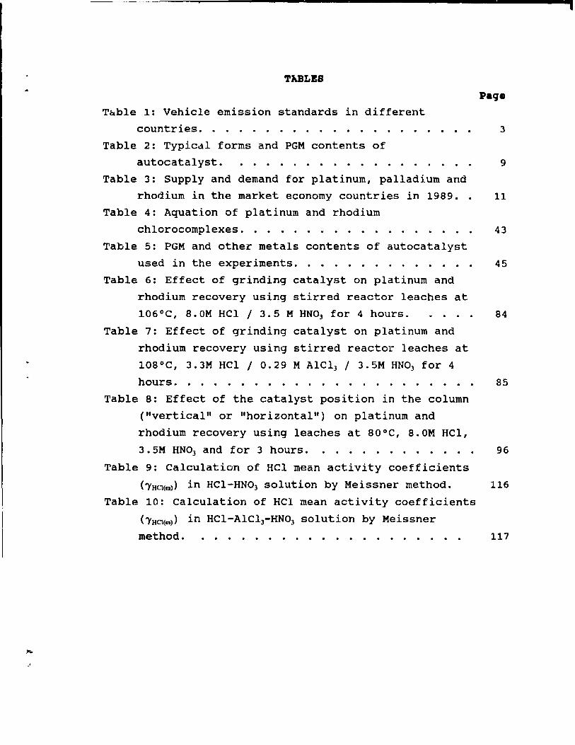
TABLES
Tâble 1: Vehicle emission standards in different
countries. . . . . . 3
Table 2: Typicdl forms and PGM contents of
autocatalyst. .......... ...... 9
Table 3: Supply and demand for platinum, palladium and
rhodium in the market economy countries in 1989.. 11
Table 4: Aquation of platinum and rhodium
chlorocomplexes. . . . . ..... . . . . .. 43
Table 5: PGM and other metals contents of autocatalyst
used in the experiments. . . . . . . . . . . . •. 45
Table 6: Effect of grinding catalyst on platinum and
rhodium recovery using stirred reactor leaches at
106°C, 8.OM HCl / 3.5 M HN03 for 4 hours. .... 84
Table 7: Effect of grinding catalyst on platinum and
rhodium recovery using stirred reactor leaches at
108°C, 3.3M HCl / 0.29 M AICl3 / 3.5M HN03 for 4
hours. . .
Table 8: Effect of the catalyst position in the column
("vertical" or "horizontal") on platinum and
rhodium recovery using leaches at 80°C, 8.OM
3.5M HN03 and for 3 hours. . . . . . . . . .
HCl,
Table 9: Calculation of HCl mean activity coefficients
85
96
(ï'HCJ(m» in HCl-HN03 solution by Meissner method. 116
Table 10: Calculation of HCl mean activity coefficients
(ï'HCJ(m» in HCI-AlCl3-HN03 solution by Meissner
method. ................. . 117
,
1
CBAP~.R 1: IMTRODUCTIOM
1.1. Introduction
Catalytic converters have been the larqest user of Platinum Group Metals (PGM) since the beginning of the 1980's (1). In the last ten years, the autocatalyst industry consumed 45-55 tonnes of PGM yearly [2]. The converter, after 4-5 years or operation in a vehicle exhaust system, becomes deactivated and is scrapped. Every year, large quantities of spent catalytic converters have entered scrapyards. Recovery of the PGM from the catalyst has evoked considerable speculation and research interest and the scrapped converters may be viewed as a substantial secondary PGM resource. This is particularly true when ve realize that PGM concentrations in the catalyst are, in qeneral, hiqher than those of the richest ore bodies. However, in 1989 no more than 7 tonnes of PGM derived from scrapped converters were recycled (3). This indicates that only 15-17' of PGM used in autoconverters is finally recycled. Further expansion of qlobal demand for autocatalyst and hiqh PGM priees raise interest for processing of autocatalyst scrap and demand for improved refininq techniques.
1.2. The hi.tory of catalytic convertera
The concept of catalytic converters as a method to reduee toxieity of vehicle exhaust qases was invented as the answer to automotive emission control standards enacted by California state in the mid 1960's (4). Two years later the first autoeonverters, containinq PGM as a catalyst were introduced. In 1970, the US Senate launched emission standards, similar to California's in aIl fifty states of the USA. The resolution, Clean Air Act, mandated a
- - l
1
2
signifieant reduetion in the level of hydroearbons and carbon monoxide emitted by automotive eXhausts, starting with the 1975 model cars. The eonverters used in those days were so ealled "two-way" converters, because they were able to oxidize the two above mentioned species. The two-way converters employed platinum or platinum-palladium alloy as a eatalyst. The US emission requiremente were followed by Japan, which also introdueed similar converters at the same time.
The emission standards were tightened in California in
1977, followed by similar criteria in aIl the USA in 1983. The new standards lower the permissible levels of
hydrocarbons and carbon monoxide, and additionally reeommend a maximum level for nitrous oxides. To me et the demands, a new generation of catalysts was designed. The new eonverters were called three-way, because they were able to eliminate the above mentioned three types of species from exhaust
gases. Three-way catalysts contain 1 to 2 g of PGM in the weight ratio Pt/Rh of 10/1, if not lower platinum. The
primary reason for aùding rhodium is to achieve the
reduetion of nitric oxide to nitrogen efficiently [5]. Japan
followed the US regulations and aiso introduced a mandatory
use of 3-way converters in 1983.
In 1992 autocatalyst will beeame compulsory in Europe. It will boost actual global demand for autocatalyst by more
than 30%. Besides Europe, several other eountries also deeided to introduee autoconverters [6]. As shown in Table
1, Australia has required autoconverters sinee 1987, Mexico
sinee 1991, and Brazil is planning to introduee them in 1992. Canada has never introduced official legislation to
use eatalytie eonverters, but aIl auto companies voluntarily
adopted US standards and aIl Canadian vehieles have been equipped with autoeonverters sinee the end of the 1970'8.
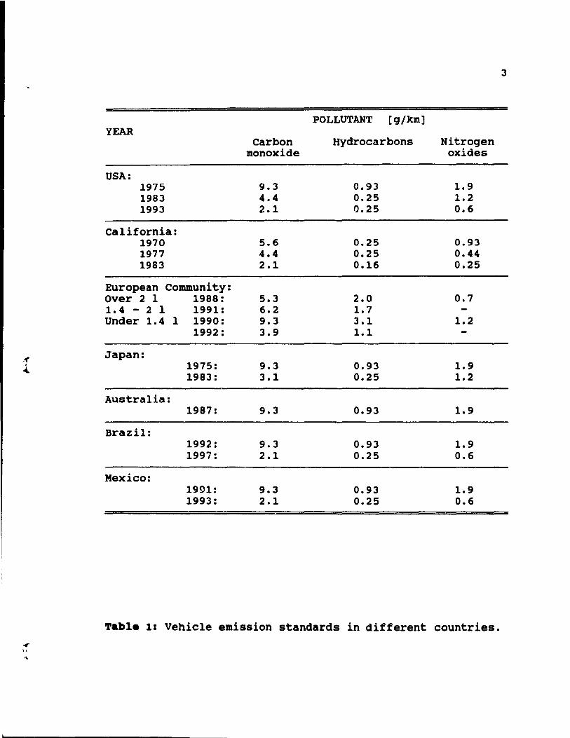
3
POLLUTANT [g/km] YEAR
Carbon Hydrocarbons Nitrogen monoxide oxides
USA: 1975 9.3 0.93 1.9 1983 4.4 0.25 1.2 1993 2.1 0.25 0.6
California: 1970 5.6 0.25 0.93 1977 4.4 0.25 0.44 1983 2.1 0.16 0.25
European Community: Over 2 1 1988: 5.3 2.0 0.7 1.4 - 2 1 1991: 6.2 1.7 Under 1.4 1 1990: 9.3 3.1 1.2
1992: 3.9 1.1
,« Japan: 1 1975: 9.3 0.93 1.9 ....
1983: 3.1 0.25 1.2
Australia: 1987: 9.3 0.93 1.9
Brazil: 1992: 9.3 0.93 1.9 1997: 2.1 0.25 0.6
Mexico: 1991: 9.3 0.93 1.9 1993: 2.1 0.25 0.6
Table 1: Vehicle emission standards in different countries • ..,. J>
4
1.3. catalytie eonverter., b •• ie 4efinition ••
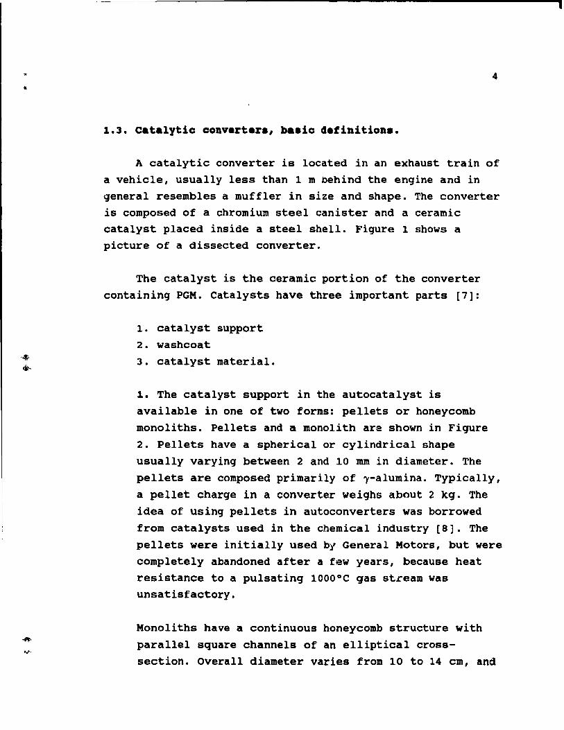
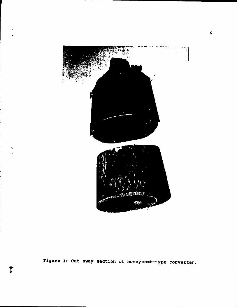
A catalytic converter is located in an exhaust train of a vehicle, usually less than 1 m behind the engine and in general resembles a muffler in size and shape. The converter is composed of a chromium steel canister and a ceramic catalyst placed inside a steel shell. Figure 1 shows a picture of a dissected converter.
The catalyst is the ceramic portion of the converter containing PGM. Catalysts have three important parts [7]:
1. catalyst support 2. washcoat 3. catalyst material.
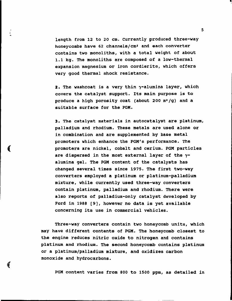
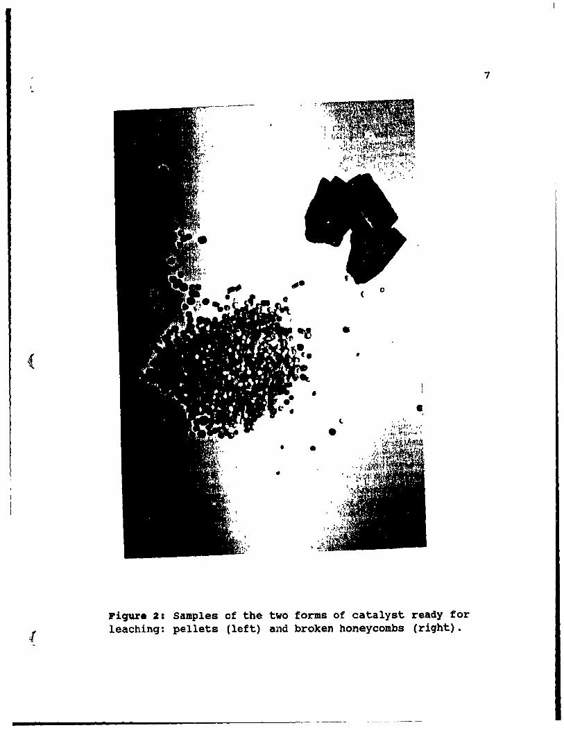
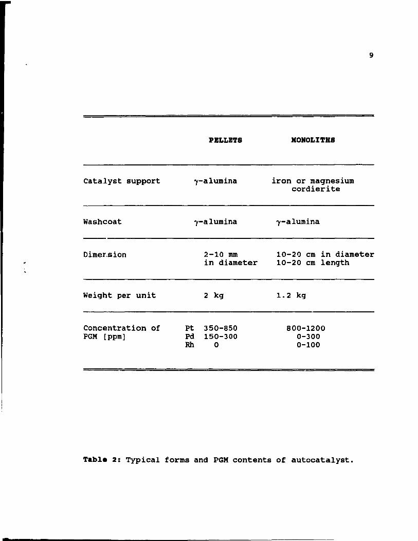
1. The catalyst support in the autocatalyst is available in one of two forms: pellets or honeycomb monoliths. Pellets and a monolith are shown in Figure 2. Pellets have a spherical or cylindrical shape usually varying between 2 and 10 mm in diameter. The pellets are composed primarily of l-alumina. Typically, a pellet charge in a converter weighs about 2 kg. The idea of using pellets in autoconverters was borrowed from catalysts used in the chemical industry [8]. The pellets were initially used bl' General Motors, but were completely abandoned after a f~ew years, because heat resistance to a pulsating 1000 0 C gas stream was unsatisfactory.
Monoliths have a continuous honeycomb structure with parallel square channels of an elliptical crosssection. Overall dlameter varies from 10 to 14 cm, and
i
(
(
length from 12 to 20 cm. currently produced three-way honeycombs have 62 channels/cm2 and each converter contains two monoliths, with a total weight of about 1.1 kg. The monoliths are composed of a low-thermal expansion Magnesium or iron cordierite, which offers very good thermal shock resistance.
2. The washcoat is a very thin ~-alumina layer, which covers the catalyst support. Its main purpose is to produce a high porosity coat (about 200 m2 /g) and a suitable surface for the PGM.
5
3. The catalyst materials in autocatalyst are platinum, palladium and rhodium. These metals are used alone or in combination and are supplemented by base metal promoters which enhance the PGM's performance. The promoters are nickel, cobalt and cerium. PGM particles are dispersed in the most external layer of the ~alumina gel. The PGM content of the catalysts has changed several times since 1975. The first two-way converters employed a platinum or platinum-palladium mixture, while currently used three-way converters conta in platinum, palladium and rhodium. There were also reports of palladium-only catalyst developed by
Ford in 1988 [9], however no data is yet available concerning its use in commercial vehicles.
Three-way converters contain two honeycomb units, which may have different contents of PGM. The honeycomb closest to the engine reduces nitric oxide to nitrogen and contains platinum and rhodium. The second honeycomb contains platinum or a platinum/palladium mixture, and oxidizes carbon monoxide and hydrocarbons.
PGM content varies from 800 to 1500 ppm, as detailed in
6
': ''''l~
.~ 1
Figure 1: eut away section of honeycomb-type convertel".
!
i .
(
[
( o
• ,
• • 1
l
•
Piqure 2: Samples of the two forms of catalyst ready for leaching: pellets (left) and broken honeycombs (riqht).
7
8
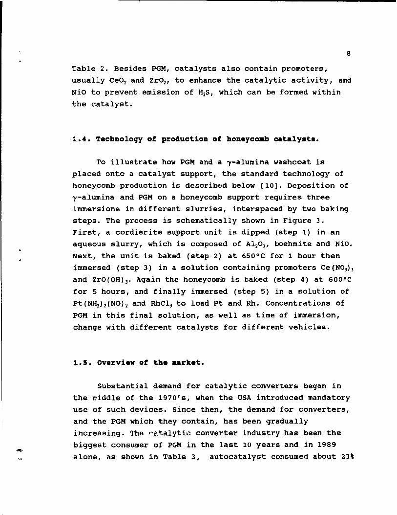
Table 2. Besides PGM, catalysts also contain promoters,
usually Ce02 and Zr02' to enhance the catalytic activity, and
NiO to prevent emission of H2S, which can be formed within
the catalyst.
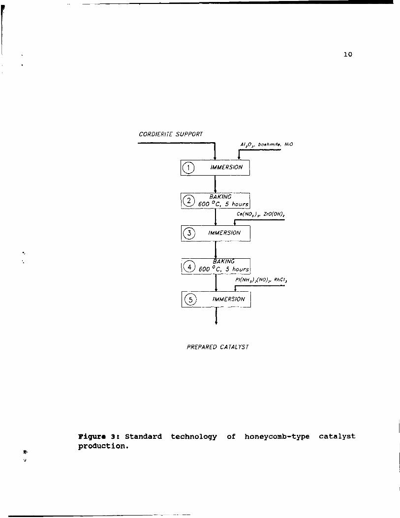
1.4. Technoloqy of production of honeycoab catalyata.
To illustrate how PGM and a ~-alumina washcoat is
placed onto a catalyst support, the standard technology of
honeycomb production is described below [10]. Deposition of
~-alumina and PGM on a honeycomb support requires three
immersions in different slurries, interspaced by two baking steps. The process is schematically shown in Figure 3.
First, a cordierite support unit is dipped (step 1) in an aqueous slurry, which is composed of A120 3 , boehmite and Nio.
Next, the unit is baked (step 2) at 650°C for 1 hour then
immersed (step 3) in a solution contél.ining promoters Ce(N03h and ZrO(OH)3. Again the honeycomb is baked (step 4) at 600°C
for 5 hours, and finally immersed (step 5) in a solution of
Pt{NH3)2{NOh and RhCl3 to load Pt and Rh. Concentrations of
PGM in this final solution, as weIl as time of immersion,
change with different catalysts for different vehicles.
1.5. Overvie. of the .arket.
Substantial demand for catalytic converters began in
the ~iddle of the 1970's, when the USA introduced mandatory
use of such devices. Since then, the demand for converters,
and the PGM which they contain, has been gradually
increasing. The catalytic converter industry has been the
biggest consumer of PGM in the last 10 years and in 1989
alone, as shown in Table 3, autocatalyst consumed about 23'
=
Catalyst support
Washcoat
Dimer.sion
Weight per unit
Concentration of PGM [ppm]
PBLLETS
"Y-alumina
"Y-alumina
2-10 mm in diameter
2 kg
Pt 350-850 Pd 150-300 Rh 0
1I0.0LITRS
iron or magnesium cordierite
"Y-alumina
9
10-20 cm in diameter 10-20 cm lenqth
1.2 kg
800-1200 0-300 0-100
Table 2: Typical forms and PGM contents of autocatalyst.
., '.
10
CORDIER/TE SUPPORT
PREPARED CATALYST
Piqur. 3: Standard technoloqy of honeycomb-type catalyst production.
, \
(
11
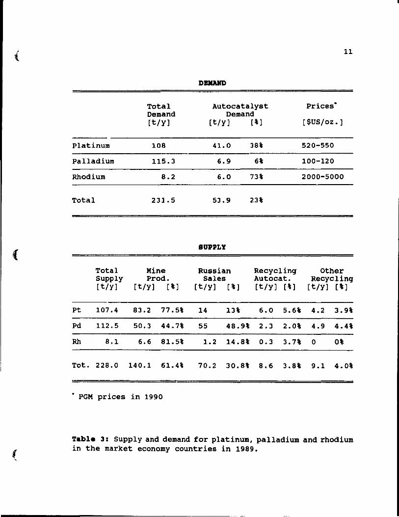
DUAIID
Total Autocatalyst Priees • Demand Demand [t/y] [t/y] [%] [$US/oz.]
Platinum 108 41.0 38% 520-550
Palladium 115.3 6.9 6% 100-120
Rhodium 8.2 6.0 73% 2000-5000
Total 231.5 53.9 23%
SDPPLY
Total Mine Russian Reeyclinq other Supply Prod. Sales Autocat. Reeyelinq [t/y] [t/y] [%] [t/y] [%] [t/y] [%] [t/y] [%]
Pt 107.4 83.2 77.5% 14 13% 6.0 5.6% 4.2 3.9%
Pd 112.5 50.3 44.7% 55 48.9% 2.3 2.0% 4.9 4.4%
Rh 8.1 6.6 81.5% 1.2 14.8% 0.3 3.7% 0 0%
Tot. 228.0 140.1 61.4% 70.2 30.8% 8.6 3.8% 9.1 4.0%
• PGM priees in 1990
Table 3: Supply and demand for platinum, palladium and rhodium in the market eeonomy eountries in 1989.
1
1
.JO"
12
of total PGM demand, equal to 53.9 t of PGM. This amount
includes 41 t of platinum, 6.9 t of palladium and 6t of
rhodium. New converters, once installed, remain in vehicle
exhaust systems for 4-5 years (an average vehicle uses 2
converters in its lifetime), and then the used units are
scrapped, collected and sent to processors. Theoretically,
almost 70% of aIl PGM used in autocatalyst could be finally
recycled [7]. However, the actual PGM recovery from scrapped
autocatalyst is much smaller (only 15-20%) due to
inefficient collection service and imperfect refining
techniques. Nevertheless, recycling provides a significant
amount of PGM. In 1989, as shown in Table 3, 8.6 t of PGM
was supplied by recycling of autoconverters. This is almost
4% of total PGM supply, or in other words, 16\ of PGM
currently used to manufacture new converters. Introduction
of this equipment in naw countries, and the tightening of
already existing standards will require more autocatalyst,
and consequently more and more of these devices will be
scrapped and available for recycling. Financial analysts
estimate that the amount of recycled autocatalyst will
double over the next five years, and consequently there will
be no decline in amount of scrapped autoconverters over the
next 20 years [1].
1.6. Recyclinq of autocatalyat.
The recycling of autocatalyst requires a chain with the
following links: dismantler, collector and processor [7].
The dismantler physically removes catalytic converters trom
vehicles at a garage or at an automobile scrap yard. Later,
he selis the entire converters to collectors. The collector
separates the catalyst from the steel containers and sells
it to a processor. The processor treats the scrapped
catalyst to remove, recover and refine the precious metals.
13
While processing methods con front a variety of technical challenges, described in later chapters, the collecting procedure is also problematic. The most difficult
problem is to determine the actual quantity of PGM contained
in the catalyst. Catalysts are usually traded at a price which depends on contained PGM value, and its estimation
requires precise sampling and analysis methods.
Another problem frequently encountered in recycling of
catalyst in North America is inability to find regular
sources of scrap autocatalyst. Collector networks
established by the Japanese are very efficient, and they
collect and send to Japan for processing 65-70% of aIl
catalyst available for recycling from the USA and Canada
( 3 ] •
1.7. Kethod of ... plinq catalyat for PGK analyaia.
Autocatalyst is a relatively homogeneous type of scrap.
Although there are va~iations in composition, a weIl mixed
and properly sampled lot will be relatively consistent
within the lot. Pellet sampling is easy to perform, and very
often a splitter box sampler is used [7]. The splitter box
functions by having equally sized and oppositely directed
discharge chutes through which the feed material is passed.
with every pass, the feed is split into two streams. One of
each is alternately used again as the feed stream. After a few passes, a small representative sample is taken.
Honeycomb catalyst is somewhat more difficult to sample
because of the irregularity in size and shape, and
segregation caused by settling of PGM rich dust. Commonly
used mineraI processing methods for evaluating monolith,
like grab sample and cone and quarter methods can be used
14
[7]. The precision of these methods is ±7t. The ±7t error in PGM concentration in the scrap catalysts can be a highly
significant factor, since it is likely to be the source of
most commercial disagreements.
1.8. Method of ana1yzinq cata1yst.
Chemical analysis of PGM in the ceramic substrate can be done in several ways. Instrumental methods involve
analysis by Atomic Absorption [11], Neutron Activation [12]
and X-Ray Fluorescence [13]. Each of the analytical method5
has its own limitations, however aIl of them have accuracy
±1-2%. It is not very significant, because when the error in
sampling is compared to error in the chemical analysis, it
can be seen that the uncertainty is much greater in the
former case (7].
1.9. Contaminations.
various contaminants are picked up from exhaust gases
and accumulated on the surface of the catalyst during its
usage. Spent catalysts contain contaminants Iike lead and
lead compounds, carbon, soot, base metals, vanadium,
phosphorus compounds and also moisture and oil. It is
obligatory that lead must be safely removed during processing, and its discharge is difficult and costly.
1.10. Lead and 18ad co.pounds.
A small amount of lead is intentionally added to most
brands of gasoline and deposited on the catalyst. As a
result, the autocatalyst converters can contain as much as
l
{
15
3-10% of lead in various forms [7]. From the processor's viewpoint, lead is the most undesirable and difficult to handle contaminant. Its' removal and safe disposaI add to the cost of PGM reclamation from scrapped autocatalyst. In the smelting route, because the oxides, sulphide, and chlorides of lead have significant volatility, the process must include provisions for capturinq the volatile lead compounds to prevent their emission both into the workplace and the environment. In the hydrometallurgical acid dissolution methods, lead may form soluble complexes which must be removed from the leaching solution to comply with environmental discharge regulations. Therefore, any process suitable for PGM recovery from automotive converters must deal satisfactorily with the lead in the catalyst.
1.11. oil.
Most scrapped catalysts contain little or no oil because unburned organic materials entering the converter are quickly burned off. Occasionally, a single catalyst unit is oil-soaked because of a malfunctionin~ engine. Oil contamination is also undesirable from the reprocessinq viewpoint. In a hydrometallurgical route, ail can prevent proper acid contact with the ceramic support and can also interfere with sOlid/liquid separation. In the smelting route, oil contamination will cause localized explosions and flash fires. Oil is not as dangerous a contaminant as lead, and most processes do not use any special treatment to remove it.
1.12. Carbon and aoot.
Deposits of carbon are not particularly harmful for the
"
16
environment, but can significantly alter PGM recoveries during hydrometallurgical treatment. The deposition of carbon or soot in a catalytic converter is a result of engine mulfunctioning, such as excessive oil consumption or hard starts in cold weather. The deposits can plug pores and channels in the catalyst structure, making part of the PGM inaccessible to leaching sol vents. Some processors suggest calcination of the catalyst at a temperature of SOO-600 0 C before leaching to eliminate the carbonaceous deposits [14]. However, high temperature during the calcination process generates volatile lead compounds, which must be captured, and also converts rhodium to a form which is highly resistant to attack by a chloride leaching solution, risking poor PGM recoveries. Thus, most processors find calcination more trouble than it is worth.
1.13. Other cont .. inant. an4 factor. to be avare of 4uring cataly.t proce •• ing.
A variety of other contaminants may be present. They include base metals, vanadium, and phosphorus compounds. The processor must be aware of their potential presence both during processing and in the resultant effluent streams.
Another problem to be aware of is that melting of the cordierite into an irregular glassy mass, which ia caused by an engine malfunction, is observed quite frequently and
perhaps 10-20' of aIl scrapped catalyst material is partially damaged (7). This disfiguration can significantly decrease PGM recovery by leaching methods.
,
17
CHAPT ER 2: PRBVIOUS .ORK
2.1. Hy4ro •• tallurqical •• tho4a.
Intensive research studies on PGM recoveries from spent autocatalyst have resulted in development of several methods of PGM extraction. Some of the processes have found industrial applications in plants operatinq in Japan and North America. Generally, recovery methods employ hydrometallurqical or pyrometallurqical steps.
The hydrometallurqical methods of PGM recovery from spent catalysts can be classified into two different groups:
J. Support dissolution techniques, which involve dissolution of the catalyst support (~-alumina) in nonoxidizinq acidic or basic solutions leavinq the PGM undisturbed.
2. Solution extraction methods, which involve dissolution of PGM in an oxidizing acidic medium. These methods aim to minimize dissolution of the catalysts' support.
The support dissolution techniques require dissolution of the entire catalyst support, and so are ineffective for honeycomb-type catalyst, which consists of acid-resistant cordierite. Since honeycombs now completely dominate the catalyst market, further study should focus on PGM dissolution from catalyst support methods rather than the support di~solution techniques. PGM in qeneral are very resistant to acid dissolution, and only a very stronq hydrochloric acid solution is able to slowly dissolve them under non-oxidizinq conditions. However, the presence of a
r 18
suitable oxidant strongly promotes dissolution. Based on this observation, almost aIl process chemistry of PGM involves the use of chiorides plus oxidant, and chloride leaching is weIl suited to noble metai recovery from spent autocatalyst [15].
2.2. oxi4anta.
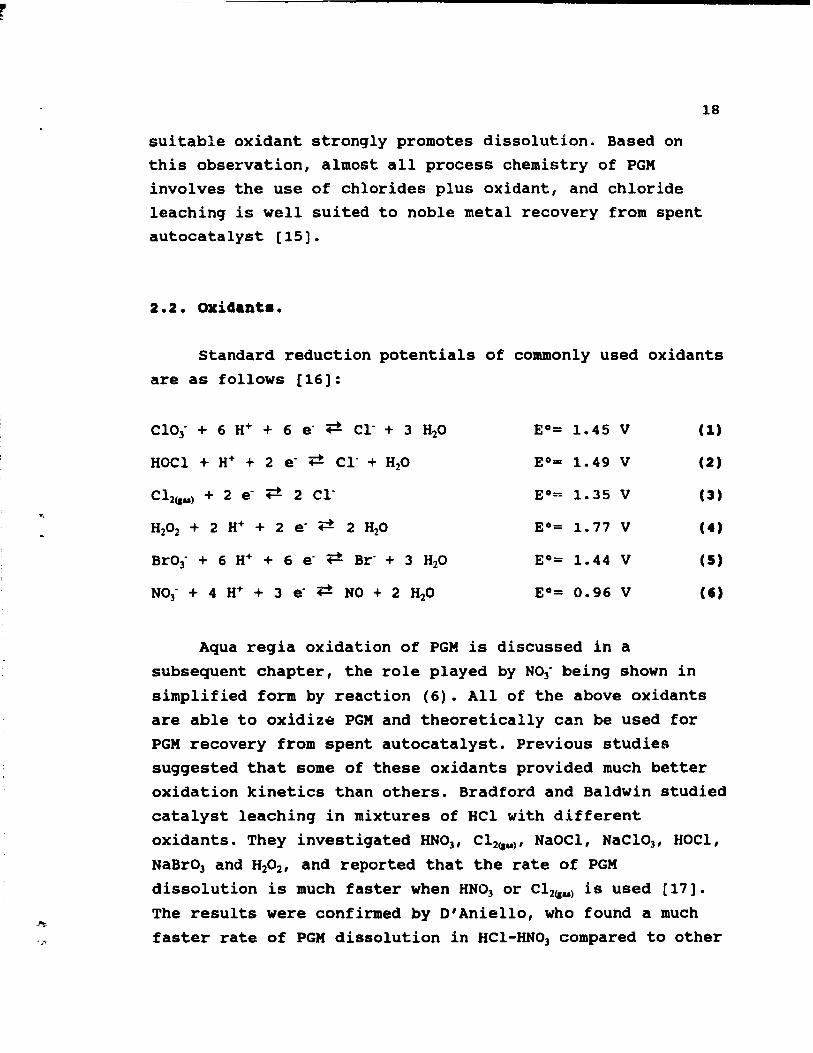
standard reduction potentials of commonly used oxidants are as follows [16]:
CIOJ- + 6 H+ + 6 e- -.=t CI- + 3 H20
HOCI + H+ + 2 e- -.=t CI- + H20
CI2{Ju) + 2 e- -.=t 2 CI-
H202 + 2 H+ + 2 e- -.=t 2 H20
BrOi + 6 H+ + 6 e- -.=t Br- + 3 H20
N03- + 4 H+ + 3 e- -.=t NO + 2 H20
Aqua regia oxidation of PGM is
EO= 1.45 V
EO= 1.49 V
EO"" 1. 35 V
EO= 1. 77 V
EO= 1.44 V
EO= 0.96 V
discussed in a
(1)
(2)
(3)
(4)
(5)
CI'
subsequent chapter, the role played by NOJ- being shown in
simplified form by reaction (6). AlI of the above oxidants are able to oxidize PGM and theoretically can be used for PGM recovery from spent autocatalyst. previous studies suggested that some of these oxidants provided much better oxidation kinetics than others. Bradford and Baldwin studied catalyst leaching in mixtures of HCI with different
oxidants. They investigated HNOll CI2{Ju)' NaOCI , NaCI031 HOCI ,
NaBrOJ and H2021 and reported that the rate of PGM dissolution is much faster when HNOJ or CI2{Ju) is used [17]. The results were confirmed by D'Aniello, who found a much faster rate of PGM dissolution in HCI-HNOJ compared to other
(
(
19
oxidizing agents [15]. Bonucci and Parker compared leaches
with HNO] and Cl2(au) and found that HNO] was a slightly more
aggressive oxidant than Cl~~ [18]. The effectiveness of
HCl-HNO] leachant was confirmed in tests do ne by Bautista
[19]. Mishra reported on the use of more than one oxidant at
the same time [20].
The above experimental data provide good evidence that
HNO) <!nd Cl2(au) are much more efficient oxidants than other
oxidizing agents, and use of one of them in catalyst
treatment is the most desirable.
2.3. Probl ... vith exc ••• ive aluaina 4i •• olution.
Many PGM extraction methods aim to minimize dissolution
of the alumina catalyst support. The ideal process should be able to extract aIl PGM from the spent catalyst leaving the
alumina support unattacked. Unfortunately, y-alumina
dissolves easily in strong HCl solution under oxidizing
conditions, and its presence in the pregnant leaching
solution has a negative impact on the economy of the
process, where excessive amounts of acids and other reagents
are required [21].
To minimize this dissolution, Bonucci and Parker
suggested converting y-alumina to a-alumina [18]. a-alumina
is a refractory compound only slightly soluble in both
acidic and alkaline aqueous solutions. y-alumina undergoes a phase transformation to a-alumina at a temperature of
approximately 1200 o C, and a simple heating of the catalyst
can greatly reduce reagent requirements during PGM
dissolution. The authors recommended preheating of the
catalyst at about 1500 0 C for 2 hours. However, this heat
20
treatment affects the reactivity of PGM, and requires a difficult and expensive capture of volatile compounds of lead contained in spent catalyst to prevent their emission
to the environment.
Lakshmanan and Ryder suggested a pretreatment reduction
of catalyst by sodium borohydride at 95°C for 1 hour [22].
This pretreatment enhances PGM ability to react rapidly with leachinq solutions, and allows use of less concentrated leachants, so also permitting reduced alumina dissolution.
Letowski and Distin proposed to suppress alumina
dissolution by using leaching mixture containing AICl3 in
partial replacement of Hel [23]. A mixture composed of 2.46M
Hel / O. 96M AICl3 / 1.46M HN03 reduced alumina dissolution to
12% of the total initial weight of pellets, leaving platinum and palladium recovery unaffected at over 95%.
The Aboye method seems to be the Most attractive for
further study, because additional pretreatment steps are not required. Fortunately, the problem with alumina dissolution
is much less critical in the case of honeycombs, because
they are composed of 85% refractory, acid-resistant
cordierite. So in the worst case, only 15% of the entire
catalyst is dissolved.
2.4. Le.ching reactora.
In general, leaching techniques include use of a
stirred reactor, a fluidized bed column reactor or a static bed column reactor. The fluidized bed column reactor was
studied and recommended by Bautista, who suggested that the
residence time could be reduced to 70% of that in a static
(
21
bed reactor (19). However the fluidized bed column required finely grounded material, and so the grinding and solid/liquid separation steps caused the fluidized bed techniques more trouble than it is worth for the autocatalyst processing. For coarse fractions, as applicable to our case where coarse, broken honeycombs or unground pellets are involved, a static bed reactor is suitable. Some proposed industrial applications envisage batch type reactors, stirred by boiling action with additional air sparging, for catalyst leaching [18] [25]. However a great advantage of column leaching is it allows production of pregnant solution more concentrated in PGM than is obtainable by leaching in a stirred reactor and two pilot plants commissioned in Canada in the 1980's found it more appropriate to use static bed column leaching reactors, which involved upward flow of solution through uncrushed pellets or coarsely cru shed honeycombs in a static externally heated column [22] [24].
2.5. Rat. of pax 4i •• olution.
A knowledge of leaching kinetics helps to determine leach retention time. Tyson and Bautista found that the rate
of platinum and palladium dissolution into a relatively weak HCl-HNOl solution (3.65 M HCl and 0.35 M HNOl ) started at
relatively high values and then dropped off very quickly over a period of time [25]. They empirically determined a kinetic expression for the experimental data, and found a logarithmic equation to fit the changes with time cf the PGM concentration in the leaching solution.
Extraction data obtained by Letowski and Distin also suggested that, for a highly concentrated solution,
dissolution of most of the PGM took place during the first hour of leaching [23]. The authors reported the extraction of 60% of total PGM during the first 40 minutes of the leaches. To obtain better leaching efficiency, use of a multistage leaching system was suggested.
2.6. Indu.trial applicationa.
22
Several hydrometallurgical flowsheets have been tested
and four of them are discussed below. The methods include: 1. Catalyst substrate dissolution by a sulphuric acid digestion [26].
2. PGM extraction from catalyst support by leaching in di lute sulphuric acid first, and then in HCI [26].
3. PGM extraction from catalyst support by chloride
leaching: CRO-Redox process [22].
4. PGM extraction from catalyst support by HCI-AICI]
HNO] leaching [27].
Process 1 is a catalyst substrate dissolution method, while
Processes 2, 3, 4 are PGM dissolution-from-catalyst-support
methods.
2.7. ~roc.aa 1: catalyat aubatrat. disaolution by a sulphuric acid 4iq.ation.
The support dissolution techniques were widely used for
treatment of spent catalyst from the petrochemical industry
and an equivalent method was developed for autocatalyst
treatment. In this method, catalyst support (~-alumina) dissolution in sUlphuric acid was followed by dissolution of
remalnlng solids, which contain pJ.atinum and palladium, in
HCl. This process was based on solubility of ~-alumina in
\ 23
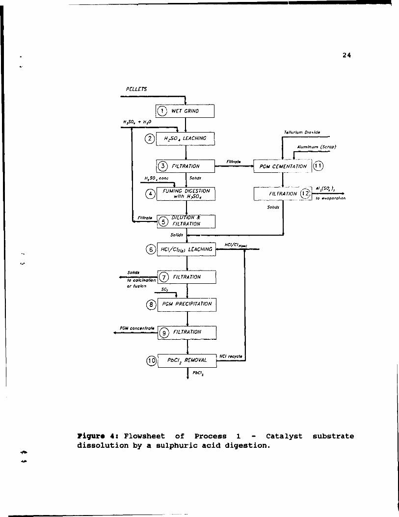
sulphuric acid, and was designed to treat pellet type catalyst. Its suitability for cordierite substrate catalyst (honeycombs) is questionable. The process is shown in Figure 4, and its steps are discussed below.
Pellets ar~ removed from their steel canisters and ground (step 1) in a rod or baIl mill to <200 mesh. To prevent lead dust emissions, wet grinding is performed. Next the pellets are dissolved in sulphuric acid (step 2) • To keep pH between 5 and 7, an excess of catalyst is added. After filtration (step 3), the filtrate, which contains small amounts of PGM, is sent to PGM recovery (steps 11 and 12), while the residue is fumed (step 4) with concentrated sulphuric acid. Next the solution is cooled, diluted with H20 and filtered (step 5). After filtration, the filtrate (sulphuric acid) is recycled to the catalyst dissolution (step 2), while remaining solids (small amounts) are combined with residues from cementation (step 11), and leached with Hel/C12 (step 6). After leaching, the solution
is filtered (step 7), and residue (very small amounts) is sent either to calcination or pyrosulphate fusion for recovery of any traces of remaining PGM. The filtrate is treated with sulphur dioxide and tellurium, which is used as a collector, to precipitate (step 8) PGM and other base metal contaminants. The reduced solution is filtered hot (step 9) to keep lead chloride in solution. Next, the solution is cooled, which allows lead chloride to crystallize, and after decantation and PbCl2 removal Hel is
recycled to PGM dissolution (step 6). Small amounts of PGM dissolved in sulphuric acid during catalyst dissolution (step 2) are precipitated from the leaching solution (together with lead and other contaminants) by cementation (step 11) with aluminum in the presence of tellurium as a collector. Again, the solution is filtered (step 12). The
24
PrLLeTS
o L-__ -.,. ___ -' Alum/num (Scrap)
PG" a";';~~/o~l@
o '-------,.---=---'---'
Soflds
Of fuslcn
Piqur. 4: Flowsheet of Process 1 Catalyst substrate dissolution by a sulphuric acid digestion.
25
filtrate (aluminum sulphate) is evaporated to produce alum for use in water treatment plants, while the solids are combined with those from fumillg digestion (step 4) and sent
to HCl/Cl2<1u) leaching (step 6).
D'Aniello evaluated this method and concluded that amounts of reagents required were too large to be economically feasible for the sparsely loaded automotive catalysts (15). Additionally, this method can be used only for pellet type catalysts, consisting of ~-alumina, which are becoming obsolete.
2.8. Proc ••• 2: PGK •• traction froa hon.ycoab. ~y .ulphuric aci4, and .~.equ.nt BCl l.ach •••
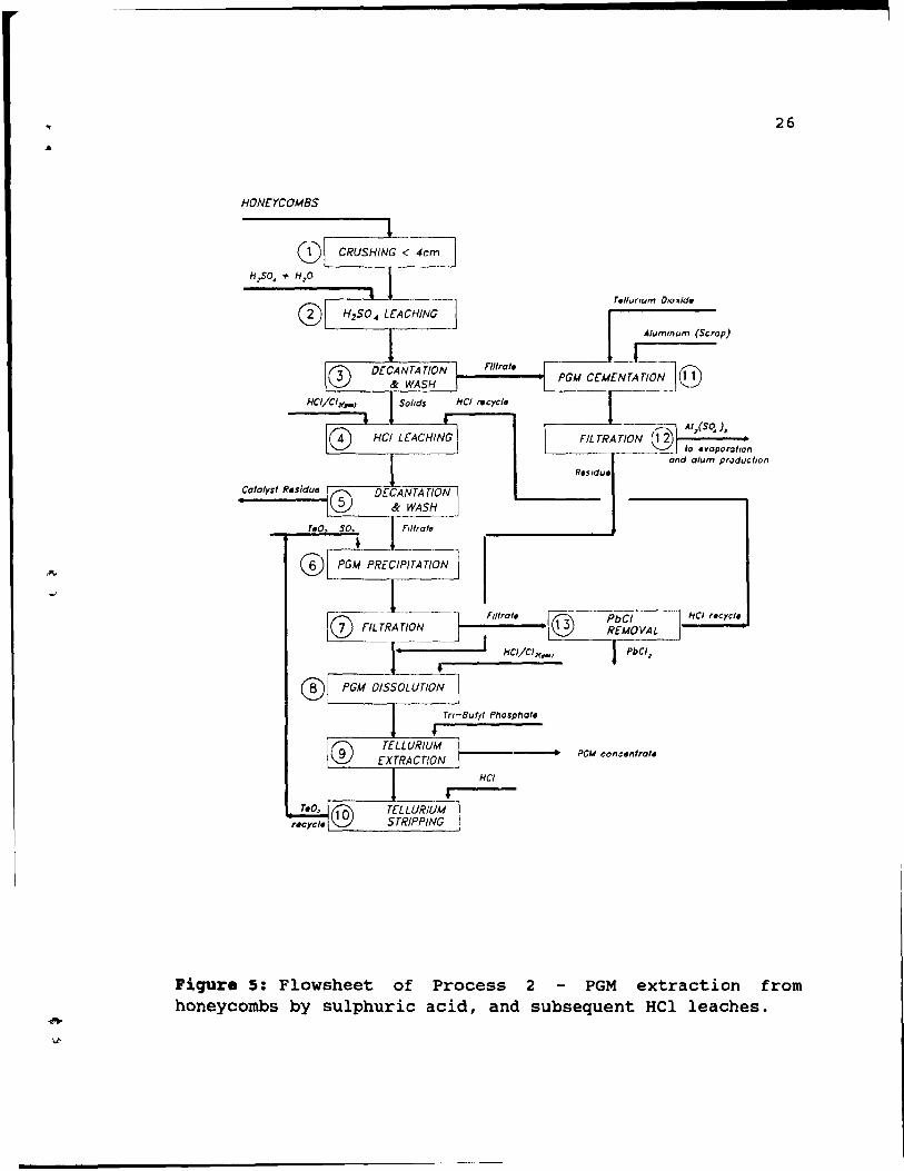
This process is used for treatment of honeycombs. The chemical concept of this method is almost the same as is used in the previously described method for pellets treatment (process 1) and includes a sulphuric acid leach to
remove ~-alumina washcoat, followed by an HCl leach to dissolve PGM remaining on cordierite substrate. The leaches leave cordierite unattacked. The process is shown in Figure 5, and i~s' steps are discussed below.
Honeycombs are decanned and cru shed (step 1) to approximately 4X2X2cm pieces to ensure complete penetration of the catalyst by leaching solutions. Next, dilute
sulphuric acid leachinq (step 2) is performed to dissolve ~alumina washcoat. This step is performed in a batch type vessel, at boiling temperature, where agitation is provided by the boiling action, and air sparging. Some PGM are dissolved by sulphuric leaching, which is followed by decantation and washing (step 3) steps. The remaining PGM is
26
HONCYCOMBS
Alummum (Scrap)
n"o," PGU c[M[~L~,;]@
__ ____ _ la evaporallon and alum producllOn
r-_~_II_,r_a_,. __ [® ~~----~------~ ~-------r------~
HCI/CI>f.-1
HCI
Piqure 5: Flowsheet of Process 2 PGM extraction from honeycombs by sulphuric acid, and subsequent HCl leaches.
. ,
---------------------------
27
dissolved during hydrochloric acid leaching (step 4) in
HCI/CI2 or HCI/HN03 solution. Following decantation, the
washes of step 5 provide nearly quantitative recovery of the solubilized PGM. Filtrate from step 3 is transferred to
cementation, where PGM precipitate by cementation with aluminum in the presence of tellurium (step 11). Optiol.ally,
hydrogen sulphide is used for the precipitation. The slurry
is filtered, step 12, the filtrate, aluminum sulphate, being
transferred to alum production, while the residue is co
mixed with PGM from step 7. Catalyst residue from step 5 is discharged to waste disposaI, while the filtrate is treated
with sulphur dioxide, using tellurium as a collector to precipitate PGM, step 6. The slurry is filtered hot, step 7,
to prevent crystallization of lead chloride, then the
filtrate is cooled, the lead chloride allowed to
crystallize, step 13, and, after decantation, the HCI is
recycled to the PGM dissolution, step 4. This recycle
eliminates a potential source of PGM losses. Freshly
precipitated PGM from step 7 co-mixed with solids from
aluminum cementation, step 12, readily redissolve in
chlorinated HCI, step 8. The volume of the solution is kept
as small as possible, because a high concentration of PGM in
solution is beneficial. The last steps include tellurium
solvent extraction, step 9, and stripping step 10. Tellurium
is recov~red from PGM solution by solvent extraction with
tri-n but yI phosphate (TBP), step 9. Some coextraction of the PGM may occur, depending on the strength of the HCl, but
none are lost, since the tellurium is recycled to the PGM
precipitation, step 6. The raffinate from step 9 contains the PGM at high concentration in a hydrochloric acid
solution, ideal for purification and recovery. Finally, the
TBP is stripped of tellurium, step 10, with concentrated Hel .
This method requires much less reagents than the
previously described Process 1, but disadvantages include
poor rhodium recovery and water balance problems.
2.9. proc ••• 3: PGX .xtraction froa cataly.t .upport by
chloride leaching: CaO-R.dox proc ••••
28
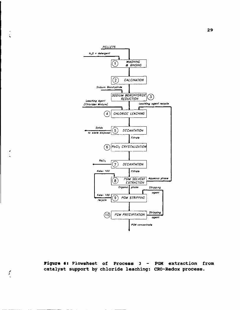
This process includes extensive pre-treatment steps,
followed by chloride leaching and PGM solvent extraction.
The process was tirst designed to treat pellets, but later
its' usability was expanded for honeycombs. The method is
shown in Figure 6, and its steps are discussed below.
Catalyst is removed from the steel canisters.
Honeycombs are crushed to approximately 4X2X2cm pieces,
while pellets are treated unground. The catalyst is washed
with detergent, rinsed, step 1, and calcined for 1 hour at
600°C, step 2. Next, catalyst is treated with sodium
borohydride, step 3, to reduce PGM oxides. The reduction is
carried out in a column reactor at 95°C and for 1 hour.
Subsequent chloride leaching, step 4, employs a hydrochloric
acid - chloride salts mixture. The leach is performed at
85°C for 6 hour.s in a column reactor under upflow
conditions. After decantation, step 5, solids are rejected,
while the filtrate is cooled. The cooling allows
crystallization of lead chloride (step 6), and its later
separation by decantation, step 7. To separate PGM from
leach liguor, solvent extraction with Relex 100 is
performed, step 8. The agueous phase is recycled to c~loride
leaching, step 4. This recycling prevents potential PGM
losses. Next, a selective stripping, step 9, and
precipitation, step 10, is used to separate PGM. The method
includes 4 extraction stages, 3 stripping stages for
palladium, and 4 extraction stages, 6 stripping stages for
L.achlng Agen / (Ch/orld.s Mlx/ur.)
8)
@
~------,-------~
~------,,------~
Piqur. '1 Flowsheet of Process 3 catalyst support by chloride leachinq:
29
PGM extraction from CRO-Redox process.
platinum. Extractant, Kelex 100, and stripping agent are regenerated and recycled.
30
This method allows good PGM recovery, but the excessive pretreatment is a disadvantage. A pilot plant using this process to treat 5 tonnes/day of catalyst has been commissioned by Platinum Lake Technology in Rexdale, ontario.
2.10. proc ••• 4: PGK •• ~ractioD froa catalyat auppor~ by
BC1-A1C13-mr~ 1.acbiIlCJ.
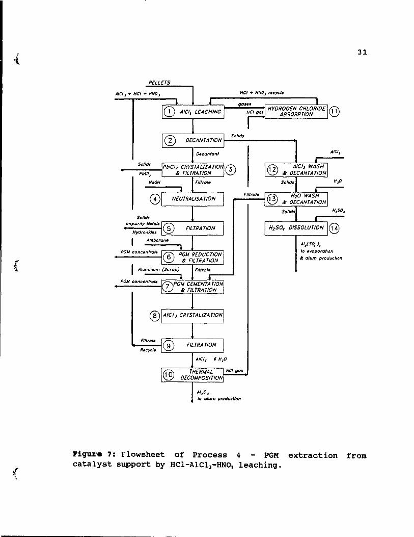
This process is applicable to PGM recovery from pellets as weIl as honeycombs. The treatment is based on a selective extraction of PGM, leaving the ~-alumina washcoat as much unattacked as possible. The method employs a HCl-AlCI3-HNOl
leach, which extracts PGM with good efficiency, and does not dissolve the entire alumina washcoat. The process is shown in Figure 7, and its' steps are discussed below.
The charge of unground pellets or cru shed honeycombs
(to approximately 4X2X2cm pieces) is leached in a teflonlined, steel tubular reactor, step 1. The leach is performed at 85-95°C for 1 hour in HCI-AICI]-HNO] solution. Gases emerging during the leach are absorbed, step 11, and HCI/HNO] solution formed during this absorbtion is recycled to the leaching step 1. Leach (step 1) is followed by two washing steps, first in Alel) solution, step 12, and then in water, step 13. During the washes, an additional amount of PGM is recovered. The washes and leaches are performed in the same column. After final decantation, step 13, pellet residue is dissolved in sulphuric acid, step 14 and transferred to alum production, while honeycombs residue is
{
AICI. + HCI + NNO.
Solld.
PbCI,
NaOH
Sollds Impurlly M.lals
HydroAId ••
mirai.
R.cycl.
31
r---~----~--------~ @
Sollds
L-______ ,-______ ~ 0)
Fllirai.
AliSo. )1
10 .vaporallon
ct alum producllon
HCI9aS
Al,O. 10 alum producllan
Fiquz~. 7: Flowsheet of Process 4 PGM extraction from catalyst support by HCI-AIC13-HN03 leaching.
r 1
32
rejected. Essentially, during leaching step 1, complete removal of impurities is achievable, leaving a purified residue that is suitable for conversion to alum. Pregnant solution from step 2 is allowed to cool, and PbCl2 is
crystallized. Next, the solution is filtered and PbC12 is
removed, step 3. A system of PGM recovery from the leaching solution consists of neutralization, by NaOH, step 4, so removing impurity metal hydroxides, step 5, sorption and reduction-to-metal on an anion exchange resin, Amborane 345 (step 6), and then cementation with aluminum, step 7. Excessively high resin consumption was experienced and the step was replaced by PGM precipitation directly from non
neutralized leach solution by hydrogen reduction. PGM concentrates from filtration steps 6 and 7 are sent to
further refining, while the filtrate is treated to allow AICl) crystallization, step 8, and filtration, step 9. The
filtrate is recycled to leaching step 1, while residue (AlCl)o6H20) is readily decomposed to HCl and alumina at over
200°C, step 10. The HCl~~ generated during the decomposition
is absorbed in the spent leach solution, step 11, and recycled to the leaching stage.
This method can be used for both types of catalyst, pellets and honeycombs. The process requires much less
reagents than the previously described methods, and although
rhodium recoveries were never studied, the method seems to
be very efficient. A pilot plant was built and operated in Boucherville, Quebec in the mid 1980's. In the future, the process will require a more economically feasible system of PGM recovery from pregnant solution, most likely a solvent extraction method.
2.11. Pyro •• tallurgical proc ••••••
(
(
33
In general, pyrometallurgical practice to recover PGJ{ from a solid source, where the PGM are in a highly dispersed form, is to melt the solid material with flux components and then contact the molten sluq containinq PGM with a molten metal pool, commonly referred to as a collector metal, into which the PGM dissolve and accumulate. Iron, copper, nickel, lead-copper, and nickel mattes are used as collector media [28]. Subsequently, the PGM containinq collector metal is treated to extract the PGM. Almost 60% of collected scrapped autocatalyst is treated in copper or nickel primary smelters, and an additional 10% is processed by another pyrometallurqical process, plasma arc smeltinq.
2.12. proc ••• 5: pri .. ry Copp.r or Nickel S •• lter ••
Primary copper or nickel smelters process the bulk of spent autocatalyst. A major advantage of the method is the absence of capital costs and minimal operatinq costs.
Smelter treatment includes crushing, grinding and mixinq of autocatalyst with the required fluxes prior to being combined with copper or nickel concentrates [25]. Dependinq on the type of smelting process employed, and the concentrate composition, additional silica or lime may be required. Copper or nickel matte is a very good collector of PGM and durinq smeltinq, the PGM report, virtually completely, in the copper or nickel matte. Only very small changes in flux additions are required by this process, incremental energy requirements are insignificant, and there is almost no additional labour costs in either smelting or refininq. Additionally, lead emissions are not a problem since aIl smelters are already equipped to deal with it. A major disadvantage is that a considerably lonqer processinq time than for other methods is required. Also some large
1
34
primary smelters may find processing of autocatalyst more trouble than is worthwhile, because cOllecting, sampling and settlement assays associated with purchasing catalyst cause a lot of problems.
2.13. proc •••• : Pl .... PU.iOD.
Plasma fusion relies on extremely high temperatures to melt alumina and cordierite. These high temperatures are generated by a very intensive heat flux produced by OC
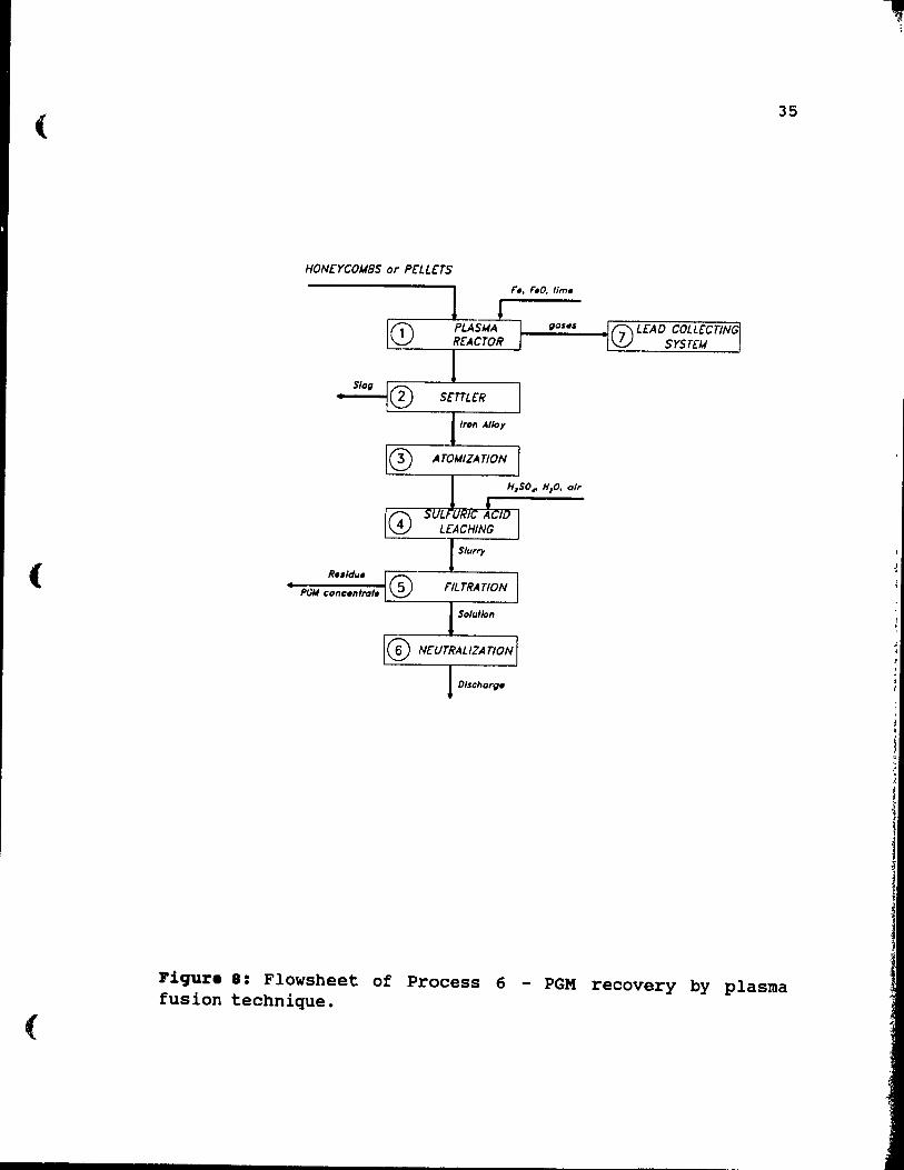
transferred plasma arc, and may exceed 2000 o C. The process is shown in Figure 8, and its' steps are discussed below [29].
Catalyst is decanned, charged to a plasma reactor, step 1, and fused with iron or iron oxide. To reduce the melting point of the feed, especially when cordierite is present, lime is added to the charge. The reactor requires a highly effective gas collection system, step 7, for control of lead fume emission. The fused charge is transferred to a settler where slag and metal phases are allowed to separate, step 2. Because of the low PGM content of the catalyst, an excellent separation is required to ensure good metal recovery. Fortunately, the large density difference between the slag and metal phases gives a good separation. Next, the slag is discarded, while the metal phase, composed of an iron alloy, is atomized, step 3, to provide an extended surface for rapid leaching. To dissolve the iron alloy and leave behind a PGM residue, sulphuric acid leaching is used, step 4. The leach slurry is filtered, step 5, leaving behind a PGM concentrate. The filtrate must be neutralized, step 6 prior to discharge. This neutralization is both costly and difficult.
(
(
(
35
HONcrCOM8S or PCLLHS
~.....;.~_as_.s_--.j 0 LCAO COLLCCTING srSTCM L..::~--r.c::....c.---'_......J
Sla~
Fiqure 8: Flowsheet of Process 6 - PGM recovery by plasma fusion technique.
"
1 1
i 1
1
i
r 36
A great advantage of the method is rapid throuqhput and easily disposable slag. Disadvantaqes of the process are cost1y lead collection systems for the plasma reactor, difficult neutralization, step 6, of discharged solution, difficult fusion and separation, step 2, when cordierite trom honeycombs is processed, and hiqh enerqy cost. Aiso low (65-75%) rhodium recovery is frequently reported. Despite many disadvantages, the plasma fusion process is operated by Multi-Metco, the successor of Texas Gulf Corp. in Anniston, Alabama as a full scale industrial installation.
2.14. other .etbo4. of PGX recovery.
Several other routes for PGM recovery have been
developed, but none of them have been tested, even on a pilot plant scale. The most important two methods include:
1. Copper collection process [20], where ground
catalyst is fused with copper carbonate or copper
oxide.
2. Dry chlorination process [20], where crushed honeycombs or uncrushed pellets are treated by chlorine
qas at 600-700 oC. PGM are converted into chlorocomplexes, which are separated and later reduced by
carbon monoxide to the elemental forme
2.15. Ch •• l.try of aqua regia.
Results of previous research show that Hel-HN03
mixture, commonly known as aqua reqia ls a much more
efficient leachant of PGM trom scrap autocatalyst than other
[
.r 1
examined agents. In the next sections, results of previous work with aqua regia are discussed in more detail.
37
Despite the fact that aqua reqia has been known and used for centuries, a composition of the mixture was never defined. In 1916, Hoke and Moore reported that chemists and chemical textbooks described aqua reqia as a mixture of HCl and HNO] but did not specify the acids ratio [30]. Some other sources defined aqua reqia as three parts of HCl and one part of HNO] taken as ordinary concentrated commercial acids [31] [32] [33]. In those days, the molality of concentrated HCl was the same as now, equal to 10.1 M, but HNO] was only 11.1 M (-16 M today). The acid ratio and molalities rouqhly corresponded to a widely accepted assumption that HCl and HNO] reacted in the ratio 3HCl/ 1HN03 •
Nowadays handbooks define aqua reqia as a mixture of 1 part of concentrated HCl and 3 parts of concentrated HNO] or 1 part of concentratad HCl, 3 parts of concentrated RNO] and 1 part of water [16]. The abc/ve definition is imprecise, and also does not mean the same as in 1916, because while molality of concentrated HCl has remained unchanqed since 1916, the term "concentrated RNO]" now means -16 M acid.
2.1'. 8pontaDeOUa 4ecoapoaitioD of aqua regi ••
When concentrated HCl and RNO] are mixed toqether and heated sliqhtly, an instantaneous and very enerqetic reaction takes place associated with a formation of brownred fumes. In 1916, Briner showed that the brown-red colour medium, which emerqed at a boundary between HCl and RNO] was
nitrosyl chloride (NOCl) [33]. Based on this observation, he
'l'.-
proposed a reaction for spontaneous decomposition of aqua reqia, as follow [34]:
38
(7)
Later, Oishi measured the specifie conductivity of diluted HCI-HN03 mixtures and found, at least for diluted acids ranging from 0.1 to 0.9 M, that the equilibrium of the HCI-HN03-H20 system could not be expressed by reaction (7),
because the equilibrium constant (X) of this reaction changes dramatically with acid concentrations [35]. He suggested the following reaction as more representative of the decomposition ~f aqua regia:
2 HCl + HN03 +=t HN02 + Cl2 + H20 (8)
Additionally, the following side reaction was assumed:
Cl2 + H20 +=t HCl + HClO Ct)
For reaction (8), an estimate of K = 90 at 30°C and for diluted aqua-reqia was made.
Reaction (7) is widely accepted for concentrated aqua regia. However, laboratory measurements were never done, and the reaction was questioned by Fleury's theoretical assumption, which postulated that nitroxyl chloride produced
in reaction (7) immediately reacts with water [36]:
NOCl + 2 H20 +=t RN03 + 3HCl (10)
Thus, similarly to diluted aqua reqia, the total reaction for concentrated aqua regia would then be better described by reaction (8) instead of (7).
A different mechanism of the dflcomposition reactlon was proposed by Walcott, who studied the oxidation potential of aqua-regia [37]. He sU9gested that NOCl was produced first, but it immediately decomposed in aqueous solutions creating nascent chlorine:
(
(
39
NOCl ;t NO(a> + Cl- (11)
Because very few specifie data about aqua regia are available, the reaction of decomposition requires further study. It seems possible that all of reactions (7), (8) and (11) take place simultaneously in the mixture.
2.17. Ba.ic cb .. iatry of platinua and rbodiua.
Platinum and rhodium are two of six closely related Platinum Group Metals - elements of Group Vlllb. They are frequently referred to as noble metals, which generally means that they are unattacked by corrosive environments under all but the harshest conditions. Nobility can be divided into its theoretical and practical aspects [38]. The theoretical nobility depends on thermodynamic stability of an element in the presence of water and is graphically described by Eh-pH diagrams. The practical nobility considers additional areas of resistance to oxidation in which the metal is thermodynami,::ally unstable and forms insoluble oxidation products. These products form a passivating film preventing or drastically slowing further reaction. Both platinum and rhodium are on the top of the list of thermodynamically noble metals. In the case of rhodium, any species formed are completely passivating and in practical terms, rhodium is the most noble metal.
The extre~ely high nobility of platinum and rhodium riecessarily requires a high temperature and a very fine grinding to increase the rate at which the metals are dissolved in aqueous media. Elevated temperatures also improve the solubilities of potentially passivating species and for example, at room temperature rhodium dissolves very
--, ,
40
slowly in concentrated sulphuric acid, while at 300°C the metal is attacked quickly [39].
Grinding of metals is even more important than high temperatures. Rhodium sheets or ingots do not dissolve in aqua regia at all. However, rhodium will dissolve surprisingly quickly in aqua regia if present at low levels in a platinum-rhodium alloy [38]. A likely explanation for this phenomenon is that solution of the platinum leaves
rhodium in a finely divided state, which increases the surface area of the metal available for attack. In our case of autocatalyst, rhodium is present as very fine particles, which can dissolve quite rapidly.
2.18. aedox reaction. in aqua reqia.
Common oxidation states for platinum are II and IV and for rhodium are l and III. For dissolution of platinum and rhodium, the standard potentials in aqueous chloride
solutions are as follows [16]:
Pt + 4 Cl" ~ PtC14"2 + 2 e" EO== -0.73 V (12)
PtC14"2 + 2 Cl" ~ PtC16"2 + 2 e" EO= -0.74 V (13)
Rh + 6 Cl" ~ RhC16"3 + 3 e" EO= -0.44 V (14)
The oxidation reactions (12) and (14) are also dissolution
reactions, while reaction (13) is a redox reaction in solution.
Since, as was discussed in a pr~viouD section, the chemistry of aqua regia is not fully understood, it is
difficult to determine redox reactions which take place in the solution and their standard potentials. Reduction
reactions of nitric acid are as follow [16]:
t
r
41
NOl - + 3 H+ + 2 e- ;::t HN02 + H20 EO= 0.940 V(15)
NO)- + 4 H+ + 3 e- ;::t NO + 2 H20 EU= 0.957 V(11)
2 NO]- + 4 H+ + 2 e" ~ N20. + 2 H20 EO= 0.803 V (17)
It has also been suggested that the oxidation potential of aqua regia is determined by nascent chlorine formation described by reactio (11) [37], and also, some authors proposed an occurrence of Cl2 reduction in the solution
[21] :
EO::: 1.358 V. (18)
2.19. PGX ozi4atioD iD aqua reqia.
Two different types of reaction representing the dissolution of PGM from automotive catalysts into aqua regia have been used. Hoffman proposed that chlorine generated by aqua regia reacted with platinum and rhodium as follows [21] :
Pt + 2 HCI + 2 Cl2 ~ H2PtCl6
2 Rh + 6 HCI + 3 Cl2 +% 2 H]RhCI6
Letowski and Distin represented the platinum reaction by [23] :
(19)
(20)
(21)
By analogy, the equivalent reaction for rhodium would be:
Rh + 6 HCI + HNO] +% H)RhClcs + NO + 2 H20 (22)
Depending on which decomposition reaction of aqua regia is assumed, the PGM dissolution reactions can be represented in different ways.
2.20. PGX .xtraction fro. praqnant 8olution by Solvant Extraction .atbo48.
42
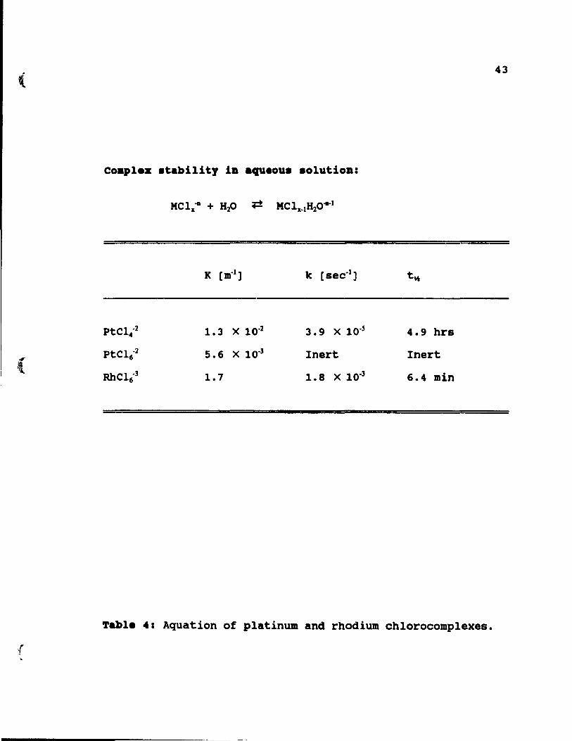
In chloride solutions, platinum and rhodium form complexes, for which thermodynamic and kinetic properties are shown in Table 4. The rhodium chlorocomplex, RhCl6-l , is
thermodynamically and kinetically unstable, and can easily be hydrolized. In aqueous solution, platinum forms a very stable PtCl6-
2 ion, which however, can also be relatively
easily hydrolized in the presence of Pt+2 [38].
Nevertheless, for high chloride concentration, the degree of
hydrolysis is low and platinum and rhodium occur as PtC16-2
and RhC16-l •
Some previous works suggested PGM reduction in the
pregnant solution by a reduction-to-metal on an anion exchange resin and then cementation with aluminum [23], hydrogen reduction [27] or PGM cementation on a mixture of
aluminum and tellurium dioxide [21]. Recent developments in
solvent extraction proved that the method is presently
considered the most suitable and powerful separation
technique for PGM. Commercially available alkylated 8-
hydroxyquinoline derivatives Kelex 100 and Lix 26 are used
by PGM refineries to extract PGM from chloride acidic
solutions (54] (55]. The processes involve the coextraction
of PGM from a feed liquor, followed by differential
stripping and may be adopted for use in spent autocatalyst
treatment [22].
( 43
Coaplez .tabi1ity ia .qg.ou. .olutioa:
PtCl .. ,2 1.3 X 10,2 3.9 X 10,5 4.9 hrs
, PtC16,2 5.6 X 10,3 Inert Inert
l RhC16,3 1.7 1.8 X 10,3 6.4 min
Table 4: Aquation of platinum and rhodium chlorocomplexes.
",'
44
CBAPTER 3 BXPDlldllTAL UD DAL Y818 •
3.1. preparation of catalyat for l •• ching.
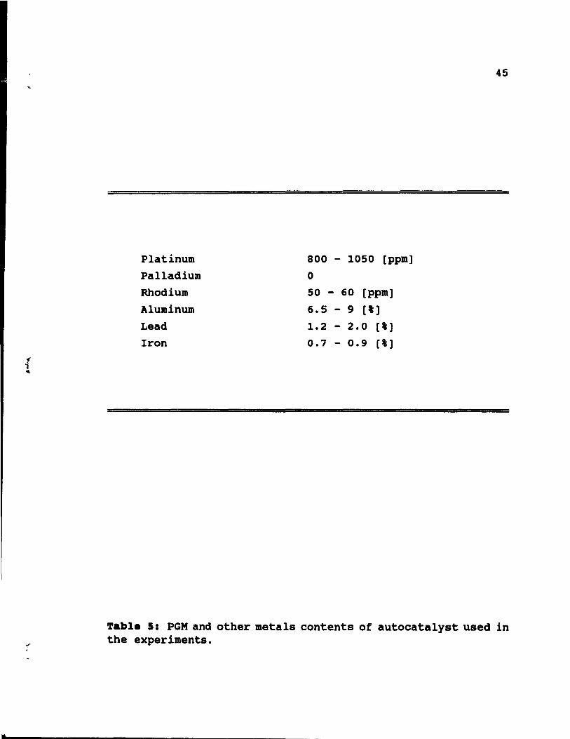
Catalyst used in the experiments were removed from several 1986-1988 Ford Tempo converters. Each converter had two honeycomb units, which had different ratios of PGM. Only the honeycombs from the front parts of the converters were used for experimentation. Detailed PGM contents of catalyst are shown in Table 5.
The monoliths were 15 cm in length and had elliptical cross-sections 12 cm in diameter. After removal from steel cans, they were manually chopped to obtain 4X2X2cm pieces. Some catalyst was further ground by a laboratory baIl mill to the size range of 60 to 120 mesh. The ground portion was used for performing tests of the effect of grinding on PGM recoveries and for analysis of the raw catalyst.
3.2. Le.ching experi •• Dta.
Leaching tests were performed in a 1000 cc kettle and in a tubular, 65 cm high glass reactor. The kettle was used for most of the tests, because it was much easier to operate than the column. Column tests were performed to study usability of a column type reactor in a large scale installation.
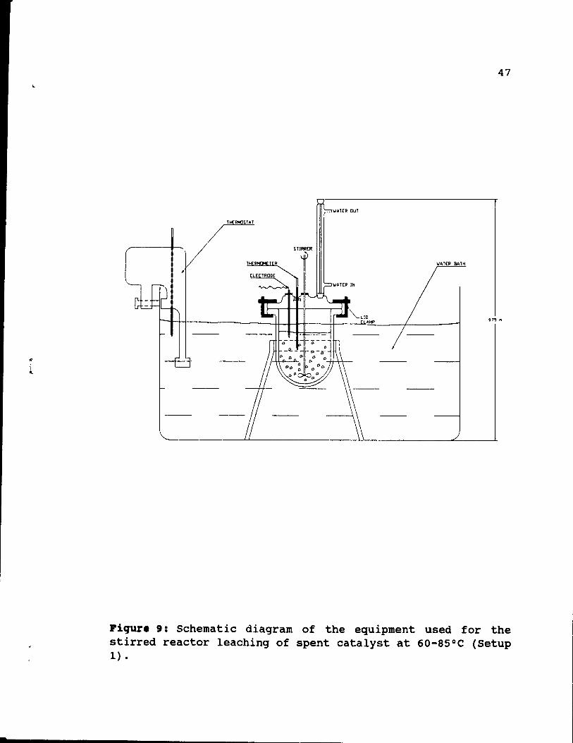
3.3. Le.ching •• tup 1.
The setup is showed in Figure 9. It consisted of a 1000 cc PYREX leaching kettle, which was placed in a water bath.
~ :1 ....
45
Platinum 800 - 1050 [ppm] Palladium 0
Rhodium 50 - 60 [ppm] Aluminum 6.5 - 9 [t]
Lead 1.2 - 2.0 [t]
Iron 0.7 - 0.9 [%]
Table 5: PGM and other metals contents of autocatalyst used in the experiments.
r 46
The bath was equipped with a Haake E-52 water heater and circulator to keep the leaching system at constant temperature (tO.5°C). The leaching kettle was fitted with a PYREX glass top with one c~ntrally-Iocated and three circumferentially-locate~ ~orts. The cap was held in place by a peripheral clamp. Solids in solution within the kettle were kept mixed by the use of a variable speed electric stirrer. The glass impeller was driven through the centrally-located outlet. A 400 mm high PYREX glass reflux condenser cooled by circulating water was held in one of the outlets to minimize evaporation losses from the leach solution. ether ports vere used to accommoda te an electrode and a 0-110 0 C thermometer. The combination pH Fisher electrode type 13-620-272 was connected to a Fisher Scientific Accumet pH-meter type 910 and was used to monitor the pH of the solution. The port which accommodated the thermometer was also used as the charging point.
This setup was used to conduct tests at up to 85°C. Aqueous solutions used for the tests were prepared from concentrated hydrochloric and nitric acids and AIC13 '6H20.
Fresh solutions were prepared shortly before experiments. In
some cases, recycled mixtures were employed. The water bath
was heated up to the required temperature by the thermostat, the kettle was filled with 235 ml of HCI-H20 or HCI-AICI3-H20
mixture and le ft for 15-20 minutes to allow the solution to warm up. Then, 65 ml of HN03 and 359 of fragmented catalyst
were added, and the first sample of solution (10 ml) was immediately taken. Slurry stirring was kept at a constant
rate of 120 rpm for aIl experiments. During the test,
samples of 10 ml of leachant were taken every hour, using a 5 ml pipette. In addition to solution analysis, solid analyses, which are much more accurate, were done. In this case, 2 pieces of catalyst were removed every hour and
.
47
"'.UR OuT
TH(RHO~UT
/ TH R T R IIATEP BATH
[lECTRaDE
075 fil
Fiqure 9: Schematic diagram of the equipment used for the stirred reactor leaching of spent catalyst at 60-85°C (Setup 1) •
.-,..
48
analyzed. Also every hour, a small portion of HNO) (10-15
ml) was added to compensate for the loss of oxidant during
the leach. After 3 or 4 hours, pieces of catalyst were
removed from the solution, final samples were taken, and the
catalyst pieces were subjected to further treatment. Some
tests were done with a finely ground catalyst. In these
cases, filtration was performed to obtain sOlid-liquid
separation. At the end of a test, the pieces of catalyst
were removed from the liquid and a sample of the final leach
solution was taken. AlI samples were then retained for
sUbsequent analysis.
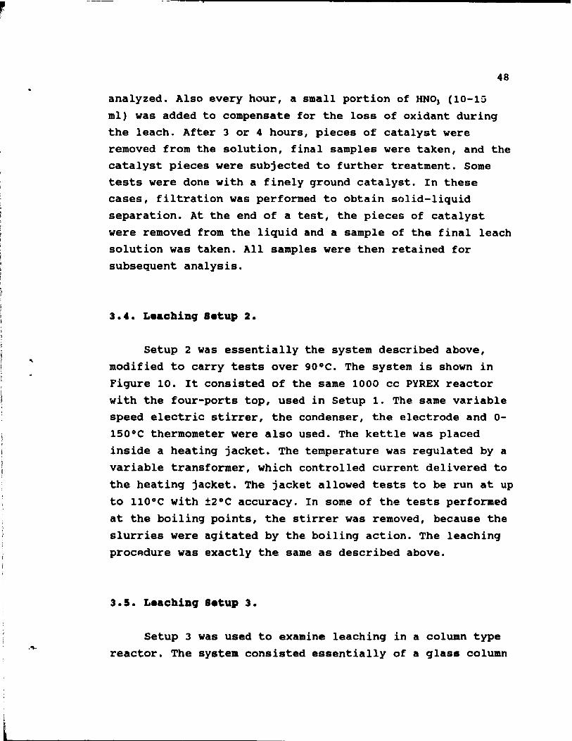
3.4. Le.ching 'etup 2.
Setup 2 was essentially the system described above,
modified to carry tests over 900C. The system is shown in
Figure 10. It consisted of the same 1000 cc PYREX reactor
with the four-ports top, used in Setup 1. The same variable
speed electric stirrer, the condenser, the electrode and 0-
150°C thermometer were also used. The kettle was placed
inside a heating jacket. The temperature was regulated by a
variable transformer, which controlled current delivered to
the heating jacket. The jacket allowed tests to be run at up
to 110°C with ±2°C accuracy. In some of the tests performed
at the boiling points, the stirrer was removed, because the
slurries were agitated by the boiling action. The leaching
procAdure was exactly the same as described above.
3.5. Le.ching Setup 3.
Setup 3 was used to examine leaching in a column type
reactor. The system consisted essentially of a glass column
lliERMoMETER
ELECTRODE
"'"
STIRRER
'oIATER OUT
'oIATER IN
065M
CLAMP
HEATING JACKET
49
Figure 10: Schematic diagram of the equipment used for the stirred reactor leaching of spent catalyst at 90-108°C (Setup 2) •
.....
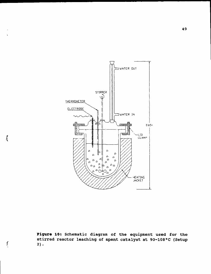
50
shown in Figures 11 and 12. The column comprised two
sections: a leaching section and a preheating section. The leaching section was 65 cm high and 5.1 cm in diameter and the preheating section was 70 cm high and 5.1 cm in
diameter. Both sections were constructed with Corning glass elements and connected through their bottoms by a teflon
tube, which had 1.5 mm inside diameter. Both sections were heated by electric heating tapes and insulated with
fibreglass. The temperature was controlled by variable voltage transformers, which allowed leaching tests up to
97°C with ±2°C accuracy. The complete installation was 160
cm high, and did not fit into a standard laboratory fume hood. To prevent the escape of fumes to the environment, the system was sealed and all fume outlets from the column were directed into the fume hood by plastic tubes. The
installation had l ports for thermometers, located at various positions, as shown in Figure 11. The total volume
of the column was 2600 cc. To maintain constant flow of
solution, 3800 cc of a leachant was used during each experiment.
Before the leaching, catalysts were manually crushed to
obtain -4X2X2cm pieces and placed inside the leaching
section of the column. Column tests required 380 to 420 9 of
crushed honeycombs. A freshly prepared mixture of HCl-H20 or
HCI-A1C13-H20 was warmed up to the required temperature and
HN03 was added. Next, thus 4500 cc of hot leaching solution
was passed through a 3000 cc storage tank 50 cm above the
column and slowly poured into the column. The feed was
leached by a continuous flow of leaching solution passed
upwards through the static bed of catalyst. The leaching
solution, which left the storage tank above the column, flowed by gravit y through the heating section of the column,
where the liquid warmed up, and then upwards through the
(
LEACHANT RESERVOIR
1 ...
51
Figure 11: Schematic diagram of the equipment used for the column leaching of spent catalyst (Setup 3).
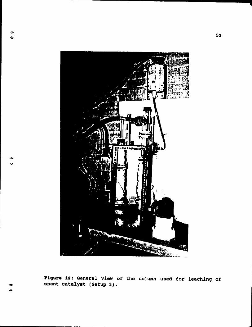
52
Piqure 12: General view of the column used for leaching of spent catalyst (Setup 3).
,
, ,
53
leaching section. A teflon tube, 1.5 mm in inside diameter, connected the warming and leaching sections of the column, and helped to maintain a slow, 3 l/hour, flow of leaching solution. The pregnant solution, which passed the catalyst bed was collected into a 2000 cc conical flask and manually
transferred to the st orage tank above the column for recirculation. The leaching tests were 4 hours long and, if the solution flow rate was kept at 3 llh, the leachant recirculated 3 times during each experiment. Every hour, a 10 ml sample of the leaching solution was taken and later analyzed. Every 0.5 hour, a 35 ml portion of HN03 was added
to compensate for loss of oxidant during the leach. After 4
hours of leaching by HCl-HN03 or HCl-AlC13-HN03 mixture, a 1
h washing by AlC13 solution followed by water was carried
out in the column. The washing periods coincided with cooling of the catalyst bed. After the wash, the column was drained, the catalyst removed and analyzed.
3.6. ADalyaia of PGK.
Quantitative analysis of PGM on the ceramic substrate can be done in several ways, including chemical or
instrumental techniques. To control production of
autocatalyst several new chemical methods, aimed
particularly to analyze honeycombs, were developed. The chemical methods give highly accurate and precise results
but are tedious, and, what is more important, require a highly skilled operator [13] [41].
More rapid instrumental methods of PGM analysis include
Atomic Absorption [41] [11], Neutron Activation [12], and xray Fluorescence [13], as weIl as recently developed-forhoneycombs Analytical Electron Microscopy [42] and Electron
•
54
Probe Microanalysis (43). Atomic Absorption Spectrometry coupled with the heated graphite furnace and Neutron Activation techniques were used to determinate PGM in our samples. AlI liquid samples were analyzed by Atomic Absorption Spectrometry at McGill university, while aIl solid samples were sent to Becquerel Laboratories Inc., Mississauga, ontario and analyzed by the Neutron Activation technique.
The instrumentation for Atomic Absorption analysis involved a Perk in-Elmer Model 403 spectrometer with deuterium background correction, an HGA-2100 and a temperature ramp programmer. Light sources were a platinum hollow cathode lamp operated at 12mA and a rhodium hollow cathode lamp operated at 14 mA. Palladium was not detected in the catalyst in the initial analyses, and was not monitored. The platinum resonance line at 265.9 nm and rhodium resonance line at 343.5 nm were used. Injected samples were brought from room temperature to 240°C in 21 sec., maintained at 240°C for 2 sec., then heated to 1850 0 C over 25 sec., and held at 1850 0 C for another 20 sec., prior
to atomization at 2700 0 C for 10 sec. A continuous flow of argon was maintained in the furnace at aIl times. Samples were analyzed as they were taken, without any conditioning.
The extremely complex matrix of leaching solution was very difficult to calibrate and finally analysis from Becquerel
Lab. helped to determine standards. Simultaneous presence of
platinum and rhodium in the solution significantly increased the platinum absorbtion signal and decreased the rhodium absorbtion signal. These interferences between platinum and rhodium caused at least 10% error in analysis. To obtain more accurate results, aIl important samples were analyzed by the Neutron Activation technique at Becquerel Lab. Additionally, aluminum was monitored by Atomic Absorption
with an acceptable accuracy ±3'.
55
CBAPTER 4: RBSULTS ABD DISCUSSION
4.1. Preliainary te.t ••
The experimental part of the study was designed to examine PGM recoveries, especially rhodium, under different leaching conditions. The results of previous work show several variables to be very important in getting high PGM extractions. Temperature, length of leaching, CI- an~ AICl3
concentration in a leaching solution were found to be the critical variables.
Before systematic tests began, preliminary work was carried out to answer the following questions:
- effect of grinding the catalyst - effect of HN03 concentration.
As shown in one of the following sections, catalyst grinding does not increase PGM recoveries from honeycombs. Breakage of honeycomb catalyst into -4X2X2cm pieces gave a
suitable leach feed. These fragments are easier to handle in both laboratory tests and industrial operation th an finely ground material.
In most cases, an UNO) concentration of 3.5 M was
chosen, this choice being based on tests described in a subsequent section. An initial addition of 3.5 M HN03 was sufficient to prevent a short age of oxidant being a
limitation on PGM extraction into solutions containing up to 8 M HCI.
Most tests were done in a 1000 cc reactor, but some were later repeated using a bench scale column. Reactor tests were done over a full range of different leaching
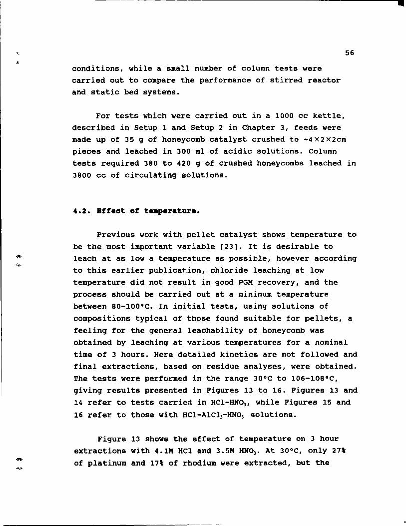
conditions, while a small number of column tests were carried out to compare the performance of stirred reactor and static bed systems.
56
For tests which were carried out in a 1000 cc kettle, described in Setup 1 and Setup 2 in Chapter 3, feeds were made up of 35 9 of honeycomb catalyst crushed to -4X2X2cm pieces and leached in 300 ml of acidic solutions. Column tests required 380 to 420 9 of cru shed honeycombs leached in 3800 cc of circulating solutions.
4.2. Bff.ct of t .. p.ratur ••
Previous work with pellet catalyst shows temperature to be the most important variable [23]. It is desirable to leach at as low a temperature as possible, however according to this earlier publica~ion, chloride leaching at low temperature did not result in good PGM recovery, and the process should be carried out at a minimum temperature
between 80-100 oC. In initial tests, using solutions of
compositions typical of those found suitable for pellets, a feeling for the general leachability of honeycomb was
obtaincd by leaching at various temperatures for a nominal time of 3 hours. Here detailed kinetics are not followed and final extractions, based on residue analyses, were obtained.
The tests were performed in the range 30°C to 106-108°C, giving results presented in Figures 13 to 16. Figures 13 and 14 refer to tests carried in HCl-HN03 , while Figures 15 and
16 refer to those with HCl-AlC13-HN03 solutions.
Figure 13 shows the effect of temperature on 3 hour
extractions with 4.1M HCl and 3.5M HN03 • At 30°C, only 27'
of platinum and 17' of rhodium were extracted, but the
•
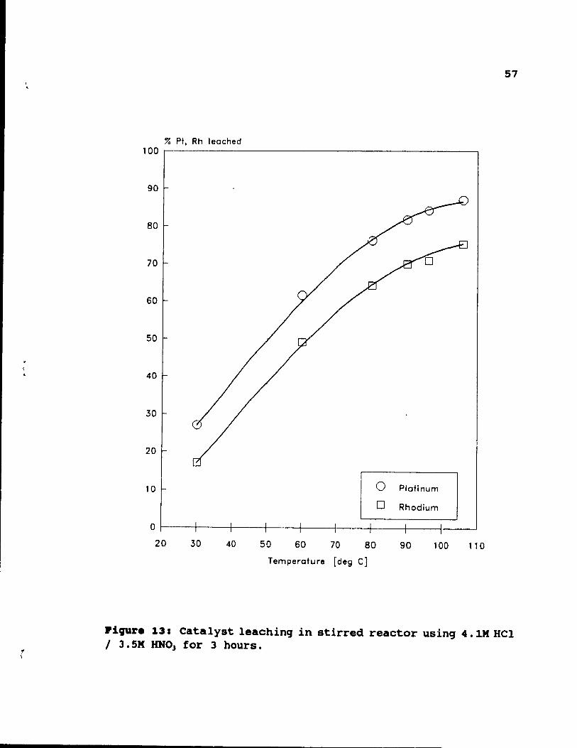
'! \
'. 57
% Pt, Rh leached 100 ~---------------------------------------------.
90
80
70
60
50
40
30
20
10 o Platinum
o Rhodium
o ~--~----~----~----~--~----~----~ ____ ~ __ ~ 20 30 40 50 60 70 80 90 100 110
Temperature [deg C]
l'i9'\l%'e 13: Catalyst leachinq in stirred reactor usinq 4. 1M HCl / J.SM RNO) for 3 hours.
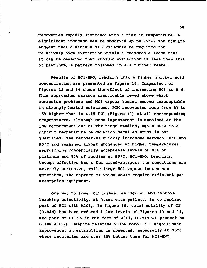
58
recoveries rapidly increased with a rise in temperature. A significant increase can be observed up to 95°C. The results suggest that a minimum of 80°C would be required for relatively high extraction within a reasonable leach time. It can be observed that rhodium extraction is less than that of platinum, a pattern followed in all further tests.
Results of HCl-HN03 leaching into a higher initial acid concentration are presented in Figure 14. Comparison of Figures 13 and 14 shows the effect of increasing HCl to 8 M. This approaches maximum practicable level above which corrosion problems and HCI vapour losses become unacceptable in strongly heated solutions. PGM recoveries were from 8\ to 15' higher than in 4.1M HCl (Figure 13) at all corresponding temperatures. Although some improvement is obtained at the low temperature end of the range studied, again 80°C is a minimum temperature below which detailed study is not justified. The recoveries quickly increased between 30°C and 85°C and remained almost unchanged at higher temperatures, approaching commercially acceptable levels of 93' of platinum and 83' of rhodium at 95°C. HCl-HNO) leaching, though effective has ~ few disadvantages: the conditions are severely corrosive, while large HCI vapour losses are generated, the capture of which would require efficient gas absorption equipment.
One way to lower Cl- losses, as vapour, and improve
leaching selectivity, at least with pellets, is to replace part of HCl with AICl). In Figure 15, total molality of Cl
(3.84M) has been reduced below levels of Figures 13 and 14, and part of Cl- is in the form of AICl) (0.54M Cl- present as
0.18M AICI). Despite relatively low total Cl-, aignificant
improvement in extractions is observed, especially at 30°C where recoveries are over 10\ better than for HCl-HNO)
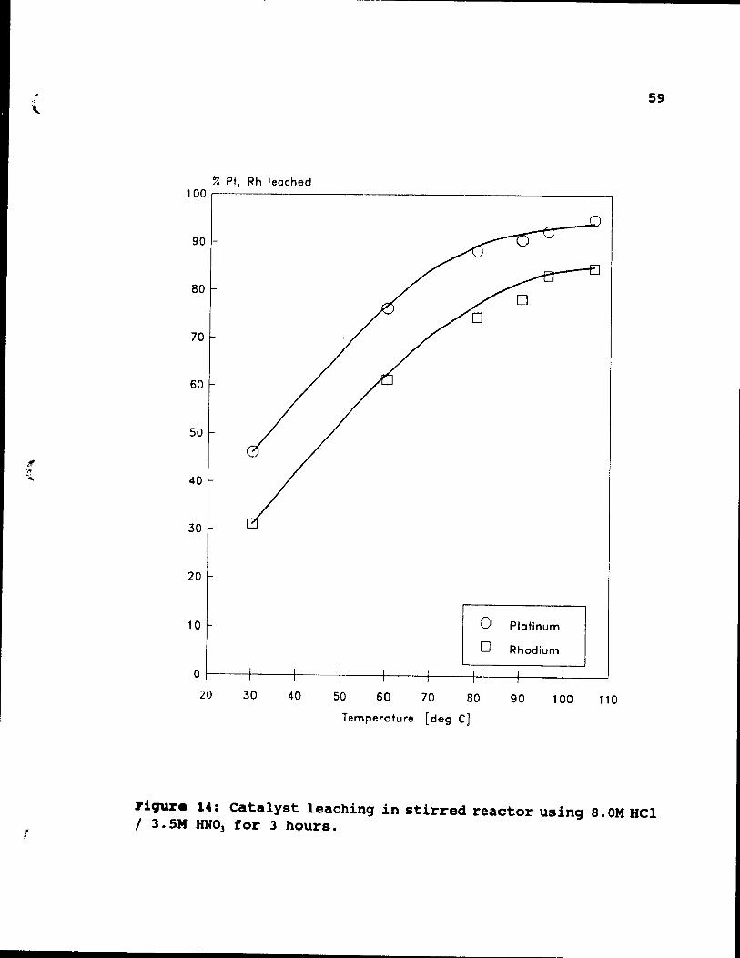
r
59
% Pt, Rh leached 100.-----------------------------
90 -
80
70
60
50
40
30
20
10 o Platinum
o Rhodium
o ~--_+----4-----+_--~----_+----~----+_--~----~ 20 30 40 50 60 70 80 90 100 110
Temperature [deg C]
PiCJUr. 14: Catalyst leachinq in stirred reactor usinq 8. OM Hel / 3. SM HN03 for 3 hours.
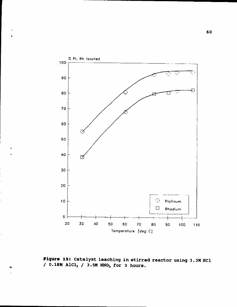
60
% Pt, Rh leached 100 .---------__________ ~
90 ~J ~I C) 1
80
70
60
50
40
30
20
10 Q ----- ---------J-C' Platinum
o Rhodium
o ~--~----~----1-----~--~-----+----1---~ 20 30 40 50 60 70 80 90 100 110
Temperature [deg C]
J'iqure 15: catalyst leaching in stirred reacter using 3. 3M HCl / o. IBM AICI] / 3. 5M RNO] for 3 heurs.
(
(
61
solution. ~GM extractions very quickly increase with an increase of temperature, and are from 5% to 8% better than for HCI-HNO] solutions (Figures 13 and 14), however hiqher temperatures are still necessary to achieve good recoveries. A temperature of 900C was considered to be the approximate optimum for leaching, because recoveries are only 2-3% lower than at the boiling point of 107°C.
Finally, the apparent effectiveness of Alel3 was examined further in Figure 16, where total CI- is further decreased to 2.53M, but AICI] is increased to 0.29M. Again, a noticeable improvement in extractions over those in Figures 12 and 13 are observed, which appears to be
attributable to AICI]. Recoveries at 106°C are extremely high: 98% of platinum and 88% of rhodium, and 2.0' and 3% respectively hiqher than for 80°C. However, recoveries drop rapidly at temperatures below 80°C, so that further work was restricted to the 80·C to boilinq point range.
The initial tests performed at various temperatures provide two general conclusi~ns:
1. Temperature plays a very important role in effectiveness of PGM extraction. Even leaching in optimally composed solutions must be at not less than 80-85°C to approach commercially acceptable levels of PGM extraction. A detailed study at below 80·C leaching temperature is not justified.
2. It appears that better results can be obtained, not by increasinq HCI concentration to very high levels, but by keeping a relatively low total CI- level with a significant proportion present as AICI,.
, ,
62
4.3. L •• chinq tinetic ••
The next step was a more detailed investigation of leaching kinetics at 80°C and higher, taking a
representative selection of solution compositions. First, Figure 17, aIl Cl- was present as HCl at close to the
maximum realistic levei 8.0M. Here extractions are based on solution samples taken during the leach. A fast leaching
rate at the beginning of the process allows recovery of 55' of platinum and 41\ of rhodium within the first hour of the process. Extractions during further leaching significantly slow down and essentially stop after 4 hours, at which
rhodium recovery is especially low at around 75%.
The temperature was then increased to 106°C, Figure 18. As might be expected, major increases in both extraction rates and final recoveries are obtained. We can reduce retention time to 2.5 hours and qet 85% rhodium and 95\ platinum recoveries. However boiling concentrated HCI
produces very severe corrosion conditions and HCI vapour
losses, which are tolerable in small laboratory tests, but
are less readily controlled on a large industrial scale.
Initial experiments indicated that the HCI-AICll -HN03
system is easier to work vith than HCI-aNOl at equivalent CI
levels, while the presence of AICI) promotes Rh extraction.
Since the AICl] content of the solution may be more critical
than a high Cl- with HCI, the total Cl- was then lowered
below 8M, and some AICI) was introduced. The benefit of
Alel), even at low total CI- and low concentration of HCI can
be seen, at 80 o e, by comparing Figures 17 and 19. Four hour
leaches, at 80°C, with 8M HCI (Figure 17) give 88\ of platinum recovery and 73\ of rhodium, while 93.6\ of
platinum and 79.2' of rhodium are extracted at the same
,
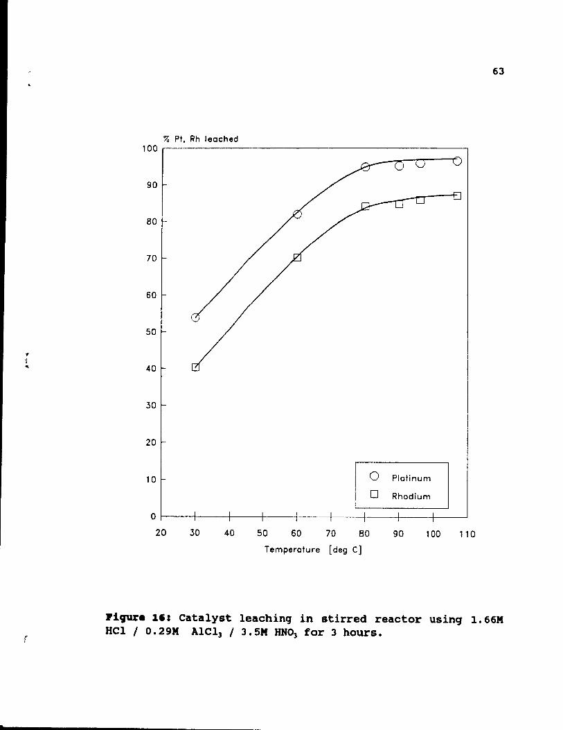
r
t
63
% Pt, Rh leached 100 ~---------------------------------------------,
90
80
70
60
50
40
30
20
10 o Platinum
o Rhodium
o ~---+----~--~~--~----+----4----~-----+---~ 20 30 40 50 60 70 80 90 100 110
Temperature [deg cl
Piqur. 1'= Catalyst leachinq in stirred reactor usinq 1.66M HCI / O.29M Alel3 / 3.5M RN03 for 3 hours.
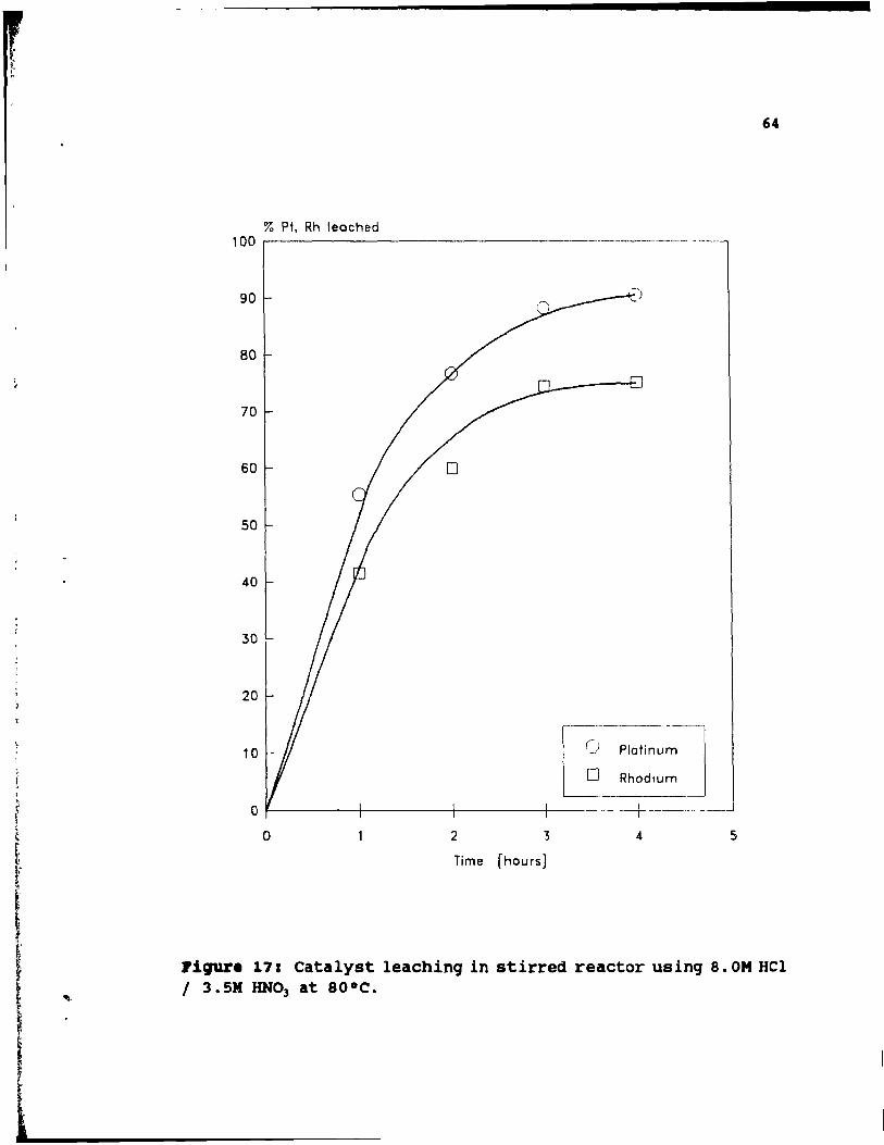
64
% Pt, Rh leoched 100 r----------------------------- ------
90
80
70
60
50
40
30
20
I-~~-~-Ietinu~-] ~ Rhodium
10
o f------+-----+------j----- --+-------a 2 3 4 5
Time [heurs]
Pigure 17: Catalyst leachinq in stirred reactor usinq 8. OM HCl 1 3.5M lINO] at sooe.
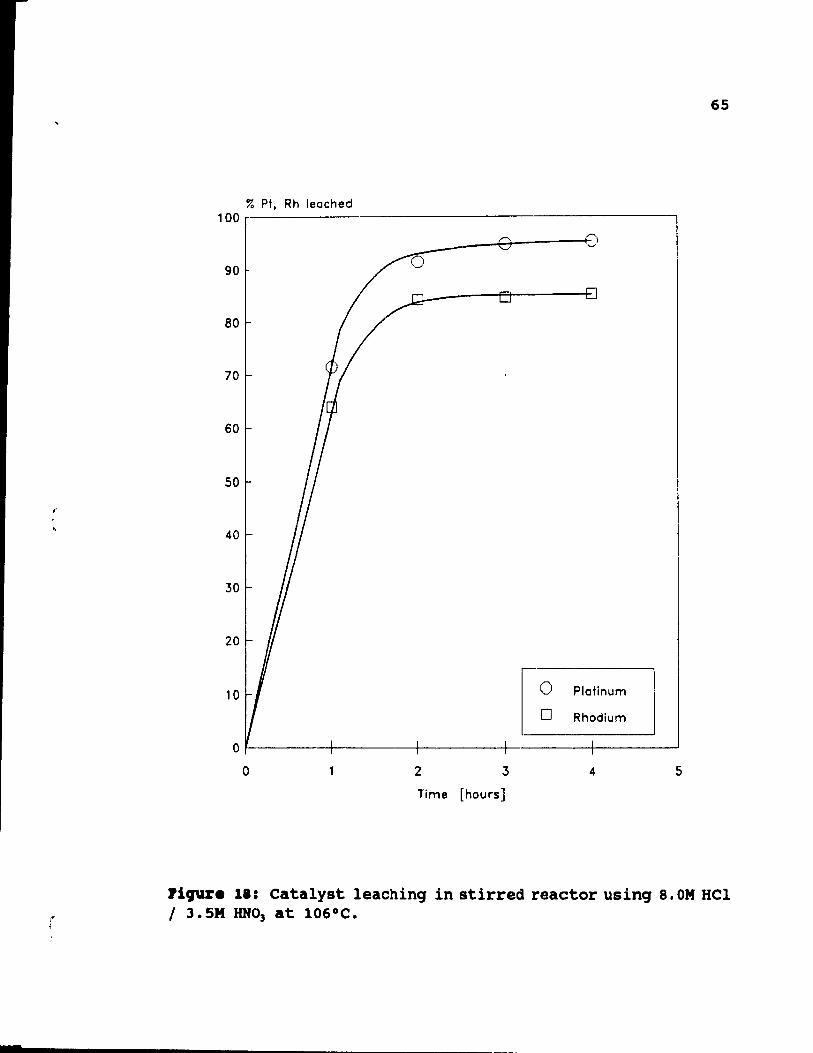
65
% Pt. Rh leoched 100~--------------------------------------------'
o E)
90
------~OA-----~D
80
70
60
50
40
30
20
[~ 10 Platinum
Rhodium
0
0 2 3 4 5
lime [hours]
rigure 11: Catalyst leaching in stirred reactor using 8. OM HCI 1 3.5M HN03 at 106°C.
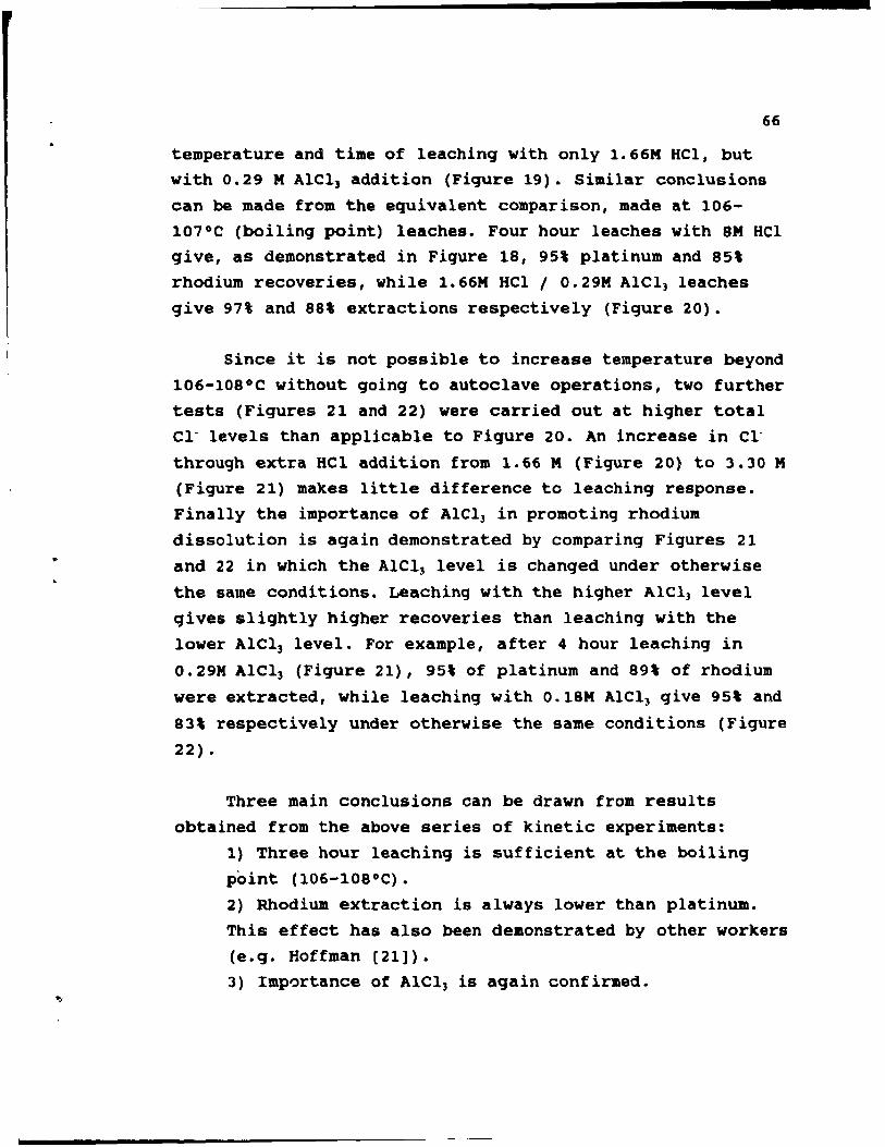
66
temperature and time of leaching with only 1.66M HCl, but
with 0.29 M AlCl) addition (Figure 19). Similar conclusions
can he made from the equivalent comparison, made at 106-
107°C (boiling point) leaches. Four hour leaches with 8M HCl give, as demonstrated in Figure 18, 95\ platinum and 85\
rhodium recoveries, while 1.66M HCl / 0.29M Alel] leaches
give 97% and 88\ extractions respectively (Figure 20).
Since it is not possible to increase temperature beyond
106-108°C without going to autoclave operations, two further
tests (Figures 21 and 22) were carried out at higher total el- levels than applicable to Figure 20. An increase in Cl
through extra Hel addition from 1.66 M (Figure 20) to 3.30 M (Figure 21) makes little difference to leaching response.
Finally the importance of AlCl] in promoting rhodium
dissolution is again demonstrated by comparing Figures 21
and 22 in which the AlCl] level is changed under otherwise
the same conditions. LeaChing with the higher AlCl) level
qives slightly higher recoveries than leaching with the
lower Alel) level. For example, after 4 hour leaching in
0.29M Alel) (Figure 21), 95\ of platinum and 89\ of rhodium
were extracted, while leaching with 0.18M AICl) give 95\ and
83\ respectively under otherwise the sarne conditions (Figure
22).
Three main conclusions can be drawn from results
obtained from the above series of kinetic experiments:
1) Three hour leaching is sufficient at the boiling
point (106-108°C). 2) Rhodium extraction is always lower than platinum.
This effect has also been demonstrated by other workers
(e.g. Hoffman [21]).
3) Importance of Alel) is again confirmed.
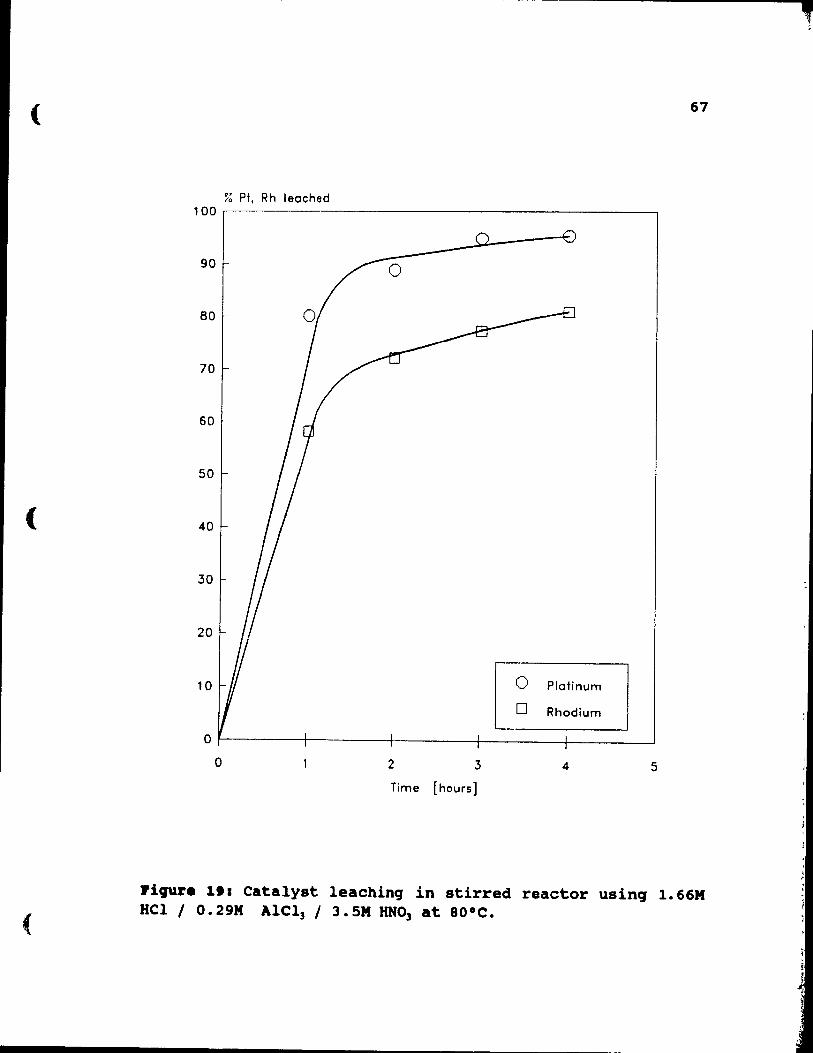
(
(
(
67
% Pt, Rh leached 100 ~----------------------------------------------,
90
80
70
60
50
40
30
20
10 Platinum
Rhodium
O~------~---------+--------~--______ ~ ________ ~ o 2 3 4 5
Time [hours]
~iqur. 111 Catalyst leachinq in stirred reactor usinq 1.66M HCI 1 o. 29M AICI] 1 3. 5M HN03 at BOoC.
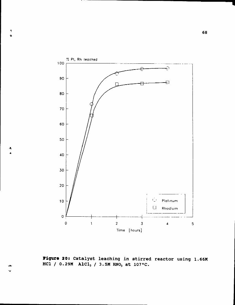
68
% Pt. Rh leached 100 r------------
__ A----_+:~
90
80
70
60
50
40
30
20
r--~- ----------
i 1 1 Plaltnum 10
1 [J Rhodium L ______________ _
o /------+--------+-------+--- --------1- --- -o 2 3 4 5
Time [hours]
Piqur. 20: Catalyst leachinq in stirred reactor using 1.66M HCl 1 O.29M AIC13 1 3.5M HN03 at 107°C.
•
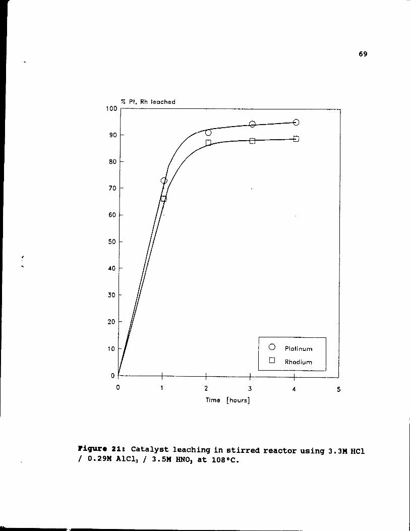
.
69
% Pt, Rh leoched 100 ~--------------------------------------'------,
90
80
70
60
50
40
30
20
10- Plotinum ]
~ Rhodium
10
O~------~------~------~-------+I ______ ~ o 2 3 4 5
lime [hours]
PiCJllr. 21: Catalyst leachinq in stirred reactor using 3. 3M HCI / 0.29M AICI) / 3.5M HNO) at 1080C •
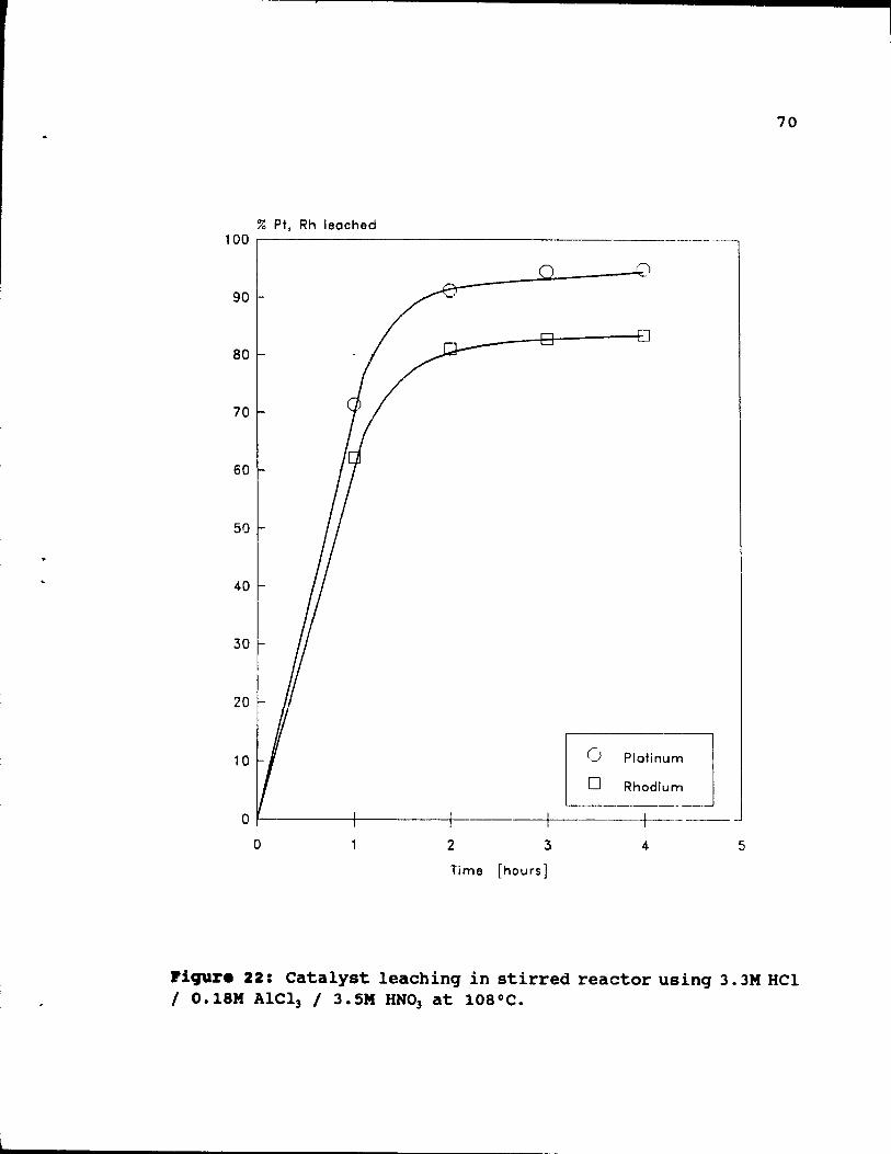
% Pt, Rh leoched 100 ~---------------------_._-_.-
90
BO
70
60
50
40
30
20
10 ü
o Rhodium Plotin;u]
L--___ _
o ~----t----+----+-----+------o 2 3 4
Time [hours]
70
5
l'iqur. 22: Catalyst leachinq in stirred reactor usinq 3. 3M HCl 1 O.18M Alel3 / 3. SM HN03 at 108°C.
71
4.4. 8ff.ct of aolutioD coapoaition.
The next step was a systematic study of effects of solution composition. Here results based on 3 hour leaches at the boiling point (106-108°C) are compared. Figure 23 shows recoveries from leaches with constant HN03 (3.5M), no AlCl] and different levels of HCl. Maximum extractions, observed at the high HCl concentration end, are 95\ of platinum and 82\ of rhodium. While platinum extraction at 95\ is reasonable, rhodium recovery at 82\ is less than desirable. It is important to note that, while recoveries rise quickly between lM and up to 8M HCl, only negligible improvement beyond this last concentration can be observed.
As can be seen in Figure 24, introduction of a small, O.18M, amount of AlC13 gives dramatic improvement in recoveries, especially at low (1-2 M) HCl levels. For example, at only 1.66M HCl, platinum recovery is 96\ and rhodium 83\. Also seen is the unexpected result that further HCl addition above 2M HCl does not improve recoveries, but in fact, slight decreases are observed.
The effectiveness of AlC13 is confirmed in Figure 25, where AlCl] addition has baen increased from 0.18M (Figure
24) to 0.29M (Figure 25). The general pattern of results in Figure 25 is similar to that of Figure 24, and dramatic improvement in recoveries is seen at low HCl levels. Maximum platinum extractions remain almost the same (96.5\> as in Figure 24, but rhodium extractions have slightly increased, with a maximum of about 88\ at 3M HCI. It seems probable that with AICl) addition above 0.29 M, the trend to better recoveries would continue, but it was difficult to prepare more concentrated Alel, solutions by the method used of
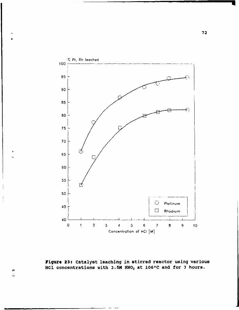
,'f
.
72
~ Pt. Rh leached 100 ,-------------------------- ------
95
90
85
~ _--+:::t----+J 80
75
70
65
60
55
50
45 0 Plct;n~ 0 Rhodium
---
o 2 3 4 5 6 7 8 9 10
Concentration of HCI [M)
J',iqur. 23: catalyst leachinq in stirred reactor using various Hel concentrations with 3.5M RNO) at 106°C and for 3 hours.
•
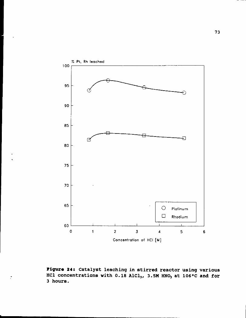
,
% Pt. Rh leached 100 ~----------------------------------------------,
95
90
85
80
75
70
65
~-~D~----~D~ ______ 8
o Plotinum
D Rhodium
60 L-______ L-______ L-______ ~ ______ ~ _______ ~ ______ ~
o 2 3 4 5 6
Concentration of HCI (M]
73
Plqure 24: catalyst leachinq in stirred reactor usinq various HCl concentrations with 0.18 AlCl], 3.SM RNO] at 106°C and for 3 hours.
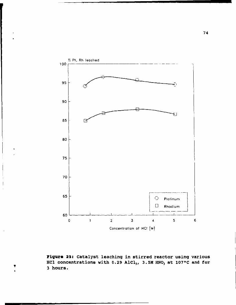
" "
~ Pt, Rh leoched 100 ,--------------- --~- -- -- - -- ~~- ~
95
90
85
80
75
70
65 o o
Plotinum]
Rhodium
60~-----L-----L----L-----~----~-----
o 2 3 4 5
Concentration of HCI [M]
74
6
Figure 25: catalyst leachinq in stirred reactor usinq various HCl concentrations with 0.29 AlCl" 3.SM RNO, at 107°C and for 3 hours.
dissolving hydrated AICI) (AICI)o6H20), because it gives a very viscous solution above 0.3-0.4 M concentration.
75
Figures 26 and 27 rearrange the results of Figures 23-25, in such a way as to show the effects of CI- source and concentrations for platinum (Figure 26) and rhodium (Figure 27) recoveries. The effectiveness of relatively low CI
levels, as AICI), especially at low HCI concentration, is
readily seen.
The above tests, performed in solutions with various HCI and AICI) contents, provide two general conclusions:
1. For leaching in HCI-AICI)-RNO), it appears that
increasing AICI) concentration tends to increase rhodium recovery, while that of platinum remains unchanged.
2. Leaching in HCI-AICI)-RNO) does not require highly concentrated solutions, because relatively low AICI)
and HCI levels assure good PGM extractions.
4.5. Concentration of .. ~.
Although platinum and rhodium dissolve in aqua regia through formation of chloride complexes, these metals are resistant to dissolution in HCI alone, because the formati~~ of the chlorides requires an oxidizing agent, which is in this case, RNO). The precise mechanism of Hel/RNO) leaching/oxidation is not weIl established, but most previous workers, as discussed more in Chapter 3, believe that HCI and HNo), react together in the ratio 3 HCI/ 1 RNO)
or 2 Hel/ l RNO) to generate an oxidizinq leachant. The
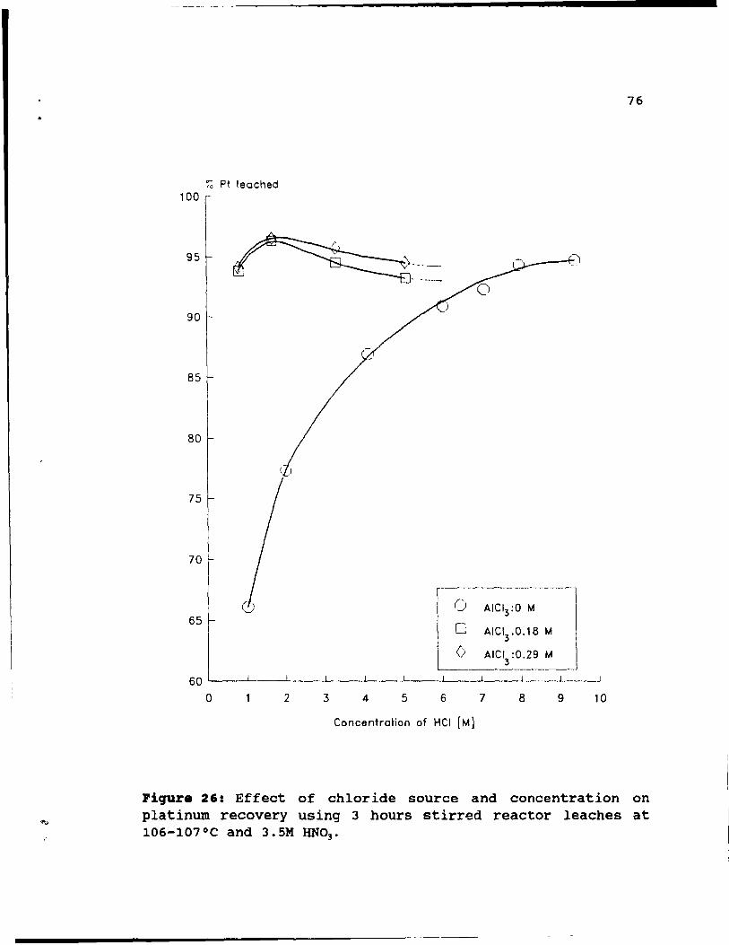
• 76
% Pt leached 100
95
90
85
80
75
70
Cl --l
AICI3:O M 65
0 AICI3
.0.18 M
(> AICI3
:0.29 M
60
0 2 3 4 5 6 7 8 9 10
Concentration of HCI [M]
Pigure 26: Effect of chloride source and concentration on platinum recovery using 3 hours stirred reactor leaches at l06-107°C and 3.5M HN03 •
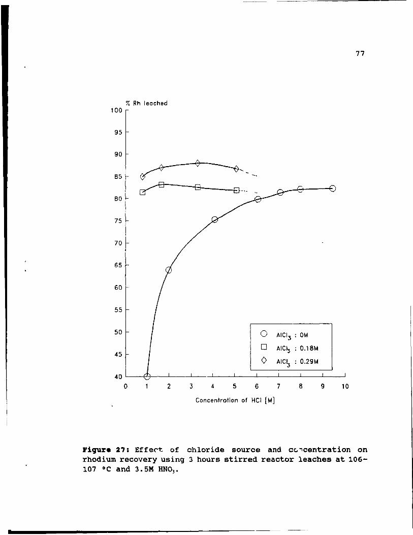
.
77
% Rh leached 100
95
90
85 -. -tr--BO-_-'8 __ _ ~
80
75
70
65
60
55
50 0 AICI3 : DM
45 0 AICI3 : O.18M
0 AICI3 : O.29M
40
0 2 3 4 5 6 7 8 9 10
Concentration of Hel [M]
Figure 27: EffeC"t of chloride source and cc. "'\centration on rhodium recovery using 3 hours stirred reactor leaches at 106-107 oC and 3.5M HNOp
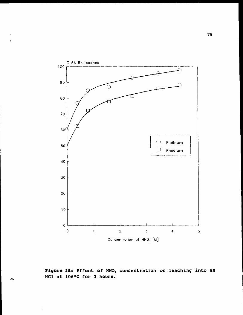
.. 78
~ Pt, Rh leached 1 00 ~------------------------ -------- -
90 ___ J
80
70
60
50 l ,~, PloHnum
o Rhodium ------~. -
40
30
20
10
o _--'--____ -L. _____ .........L ____ ~ ______ _
o 2 3 4 5
Concentration of HN03 [Ml
piqure 28: Effect of RNO, concentration on leachinq into 8M HCl at 106°C for 3 hours.
(
(
f '.
79
effect of HNO] on its own is to oxidize the metals through
reactions evolving NO and N02 - It may also be assumed that HNO] not only generates a strong oxidation potential in HClHNO] mixtures, but also controls ionic activities by contribution to the overall dissolved H+ concentration. To
evaluate the impoI'tance of KN03 , tests were conducted in the o M to 4. 3M range in both HCI - HN03 and HCI-AlCl]-HNO]
mixtures.
Figure 28 shows the effect of HN03 on PGM extraction into 8.0M HCl. Leaching without HNO] allows recovery of
60.4\ of platinum and 50.1\ of rhodium. Results suggest a minimum of 1 M RNO] would be required for significant extraction, while further increases in molality give gradually increasing recoveries.
Other tests, for which results are presented in Figure 29, were done in HCl-AlC13-HNO] solution. At zero HNO]
concentration, the results show up to 25\ lower extractions than for HCl-KN01 (Figure 28) and it appears that about 1.6
M is a minimum concentration below which recoveries quickly decrease. ,~gain, a further increase (over 1.6M) of the HNO]
molality qives substantially improved extractions.
It should be noted that there is significant extraction at zero HNO], but this may not be a true PGM dissolution process. Here, HCl, on its own, may be dissolving the alumina coat releasing tiny particles of PGM into the solution. This apparent extraction may result fram the recoveries of Figures 27 and 28 being based on residue analyses.
The above tests produce two overall conclusions:
• 80
1. Leachinq without RNO] or in small concentrations of
RN0 3 is ineffective.
2. Despite the fact that recoveries are significant in leaches containing about 1.6M HNO], a further increase
in this acid concentration (up to 3-4 M) would qive an extra 10' rise in extractions. At more than 4 M HNO l ,
in a boiling solution, corrosion and toxicity problems become severe. Thus 3.5M HNO) was chosen as the
standard for experiments described in the previous and
followinq sections.
4.6_ Eff.ct of qrin4iDq_
Grindinq is a frequently employed operation in ore
treatment processes, and is used to liberate locked particles of the desired mineraI trom the ore body to increase final recoveries. In the case of artificially produced catalyst, liberation of PGM particles by grindinq may be not necessary, because they are exclusively dispersed
in the surface of the catalyst substrate. Previous work done
with pellets not only does not recommend grinding of catalyst, but even strongly advises against it [23). PGM
were not locked inside the pellets, but dispersed in their outermost surface, which is easily reached by the leaching solution. Grinding of pellets not only did not increase PGM recoveries, but, in fact, added a new problem, i.e. an increased amount of A120] dissolved during leaches. In the
case of pellets, one of the main goals of the recovery process was to minimize the amount of dissolved aluminum in
the leaching solution to avoid an extra cost of chemicals
used for solution treatment.
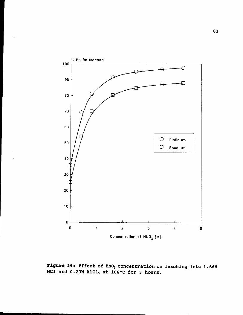
.
% Pt, Rh leoched 100~----------------------------------·------------,
40
30
20
10
o Plotinum
D Rhodium
OL-------~--------~ ________ ~ ________ ~ ________ ~
o 2 3 4 5
Concentration of HNOa [M]
81
riCJUZ'. 2': Effect of RNO) concentration on leaching int..: 1. 66M HCI and 0.29M AICI) at 106°C for 3 hours .
82
The above considerations are less applicable to honeycombs, because the structures of pellets and honeycombs are very different. Honeycomb catalyst has narrow internal channels difficult to penetrate by the leaching solution, and this suggests that, to increase PGM recoveries, honeycombs, unlike pellets, may require grinding to expose PGM trapped inside the channels. Excessive A120) dissolution
is not a problem, because honeycombs are mostly made of acid resistant cordierite.
A few leaches were done to study the effect of grinding of honeycombs on PGM extraction. The tests were 4 hours long, and carried out using a 1000 cc reactor at -106°C in HCI-HN03 or HCI-AIC13-HN03 solutions. Catalyst was separated
into three parts and ground into three different sizes: 1. 4 X2 X2cm pieces 2. 2 X2 X 1mm pieces 3. < 60 mesh
Results of leaches are shown in Tables 6 and 7. The results indicate that there is almost no difference in extraction of PGM between qround « 60 mesh or 2X2Xlmm pieces) and
unground (4X2X2cm pieces) catalyst. In all tests, recoveries are 94% for platinum and 85% for rhodium if leaches are performed in HCI-HN03 (8.0M/3.5M) solutions, or
95% and 87% for leaches in HCI-AIC13-HN03 (3.3M/0.29M/3.5M).
The main conclusion from this set of tests is that leaching solution has, in fact, no trouble penetrating catalyst channels.
4.7. Coluan l •• ching.
In column leachinq, scrap catalyst is leached as a static bed in a tubular reactor, through which an upward
" ..
'Y 1 'l
flow of leachant is passed. This system has the following advantages over other types of reactors:
83
1. It gives solutions more concentrated in platinum and rhodium than obtainable using a stirred reactor due to a high solid/liquid ratio acquired by circulation of as small an amount of leachant as possible.
2. A sOlid/liquid separation step is avoided.
Since it has been previously shown that fine grinding is not required for honeycombs, a column vessel can be used for leaching of this type of catalyst. In the present work, most testl; for optimizing leachant composition and temperatul:-e were carried out using a stirred reactor system, as described above, because when a relatively large number of experÎDlents under different conditions is required, this latter met:hod is more convenient to operate than column leaching. A few column tests, which used leaching solutions approximating those of optimum composition determined earlier in reactor tests, allowed leaching kinetics in the column to be compared with results found previously with the reactor. Since the most desirable equipment to use on an industrial scale is a tubular type reactor, the test carried out in a li!lboratory scale column allow direct scaling up, because the! leaching procedure is the same in both cases: continuously flowing solution passes through a static-bed of
crushed cat:alysts. The column tests were done at 80-82°C and 94-97°C, instead of the boiling point (106-108°C), because bubbles generated at the boiling temperature perturb the smooth unbroken flow of solution. In each test, 380-420 9
catalyst, broken into 4X2X2cm pieces, was leached in a 3-4 l/hour upward flow of circulating leachant.
Similarly to reactor tests, the first experiment,
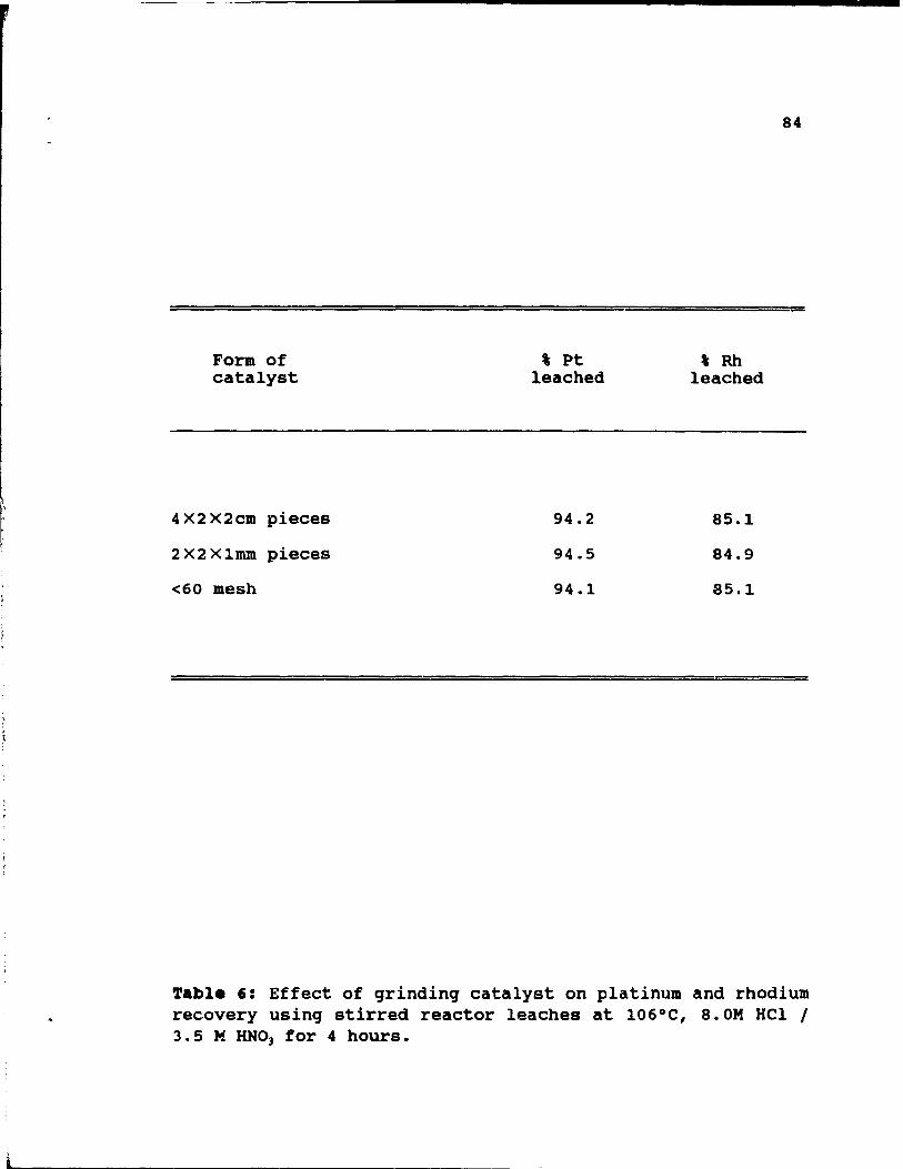
," r i· ;
Form of catalyst
4X2X2cm pieces
2X2X1mm pieces
<60 mesh
, Pt leached
94.2
94.5
94.1
,Rh leached
85.1
84.9
85.1
84
Table 6: Effect of grinding catalyst on platinum and rhodium recovery using stirred reactor leaches at 106°C, 8.0M HCl 1 3.5 M HN03 for 4 hours.
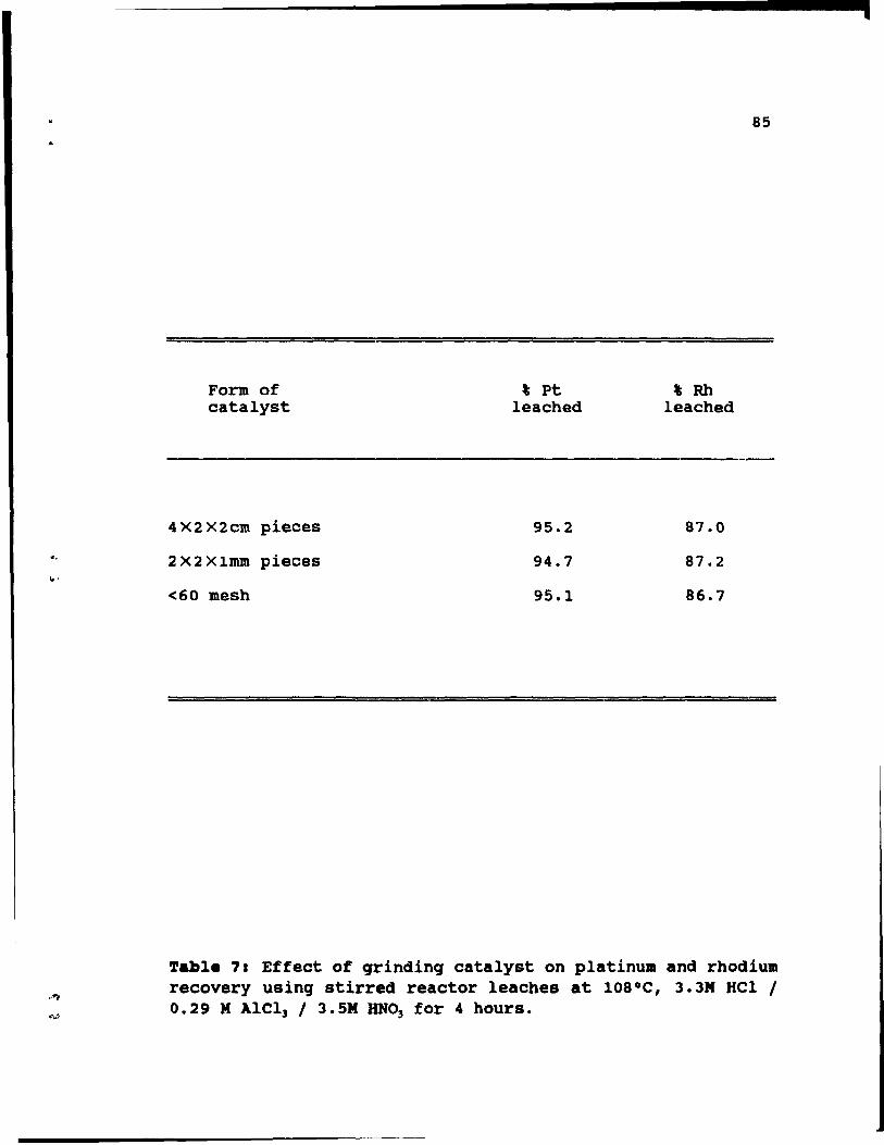
..
Form of catalyst
4 X2 X2cm pieces
2 X 2 X 1mm pieces
<60 mesh
% Pt leached
95.2
94.7
95.1
,Rh leached
87.0
87.2
86.7
85
'able 7: Effect of qrindinq catalyst on platinum and rhodium recovery usinq stirred reactor leaches at 108°e, 3.3M Hel / 0.29 M Alel] / 3.5M RNO] for 4 hours.
,
(
(
86
Figure 30, was performed at 80°C, with aIl Cl- as HCl at close to the maximum realistic level (8.0M). Results are based on analysis of solution samples taken during the leach. By comparing stirred reactor and column results for the same conditions of solution composition and temperature (Figure 31) it can be seen that both platinum and rhodium extraction curves are virtually independent of reactor type, a conclusion that ho Ids in aIl cases where tests using the two different systems were carried out under comparable conditions. It is surp~ising that, despite the arbitrary choice of stir4ing rate or solution flow rate, reaction kinetics are so insensitive to reactor confi~'~~ation. The conclusion mUEt be that reaction rates are controlled by the interfacial dissolution reactions rather ~han by mass transfer effects.
As might be expected based on the results of reactor leaches, major increases in both extr.action rates and final recoveries are obtained when the temperature is increased from 80°C to 96°C, Figure 32. Here, at least 4 hours is required to assure high recoveries, these being 93' for platinum and 85' for rhodium.
On account of the results obtained during reactor tests, special attention was paid to HCl-AlCl]-HN03 leaches, because there is no doubt that AlCl] addition to a leaching solution not only makas the system easier to work vith, but also produces higher recoveries. The benefit of AlCl] addition, similar to that observed from reactor tests, can be se en by comparing Figures 29 and 32, which apply to about 80°C. Figure 33 shows results of lea~hing in HCl-AICl]-HNO] at auch lower total chloride (2.53M) than for Figure 30, where 8 M total chloride, aIl as IICl, applies. The results confira previous findings that PGM recoveries are better in
•
,
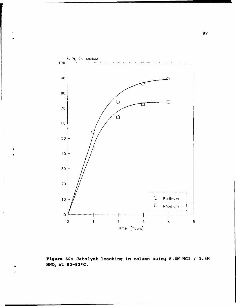
87
% Pt. Rh 1 eached 100 ~----------------------------------
90 ---~
80
70
50
40
30
20
--
10 0 Platinum
0 Rhodium
0
0 2 3 4 5
Time [hours]
~iqur. 30: Catalyst leachinq in column usinq 8.0M HCl / 3.5M RNO] at 80-82°C.
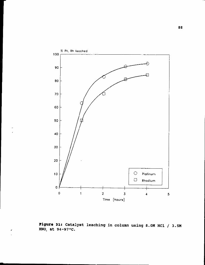
.
88
% Pt, Rh leached 100~----------------------------------------
70
60
50
40
30
20
10 0 Platinum
0 Rhodium
0
0 2 3 4 5
Time [hours]
Piqur. 31: Catalyst leachinq in column usinq 8.0M HCl 1 3.5M HNO~ at 94-97°C .
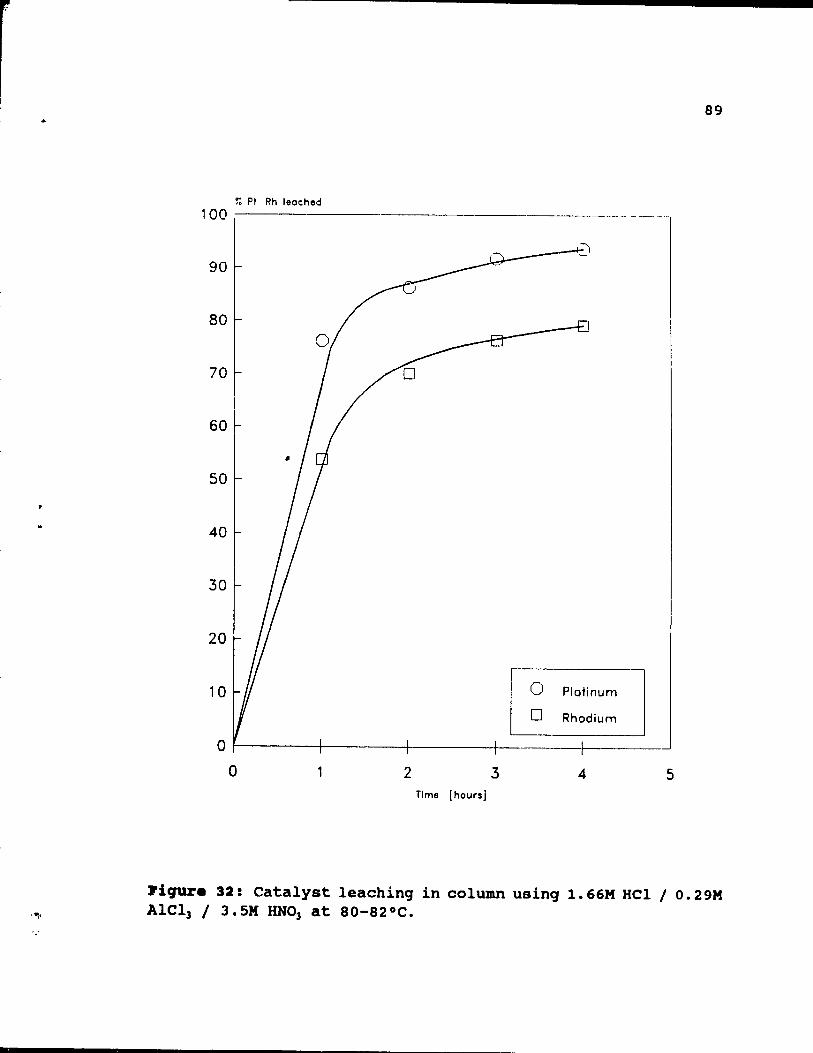
89
~ PI Rh leached 100 --------.-------- ._--
90
80
70
60
50
40
30
20
10 Platinum
Rhodium
0 -1 0 2 3 4 5
Tlme [hours]
l'iqura 32: Catalyst leaching in column using 1. 66M HelIo. 29M AICl3 / 3.5M RN03 at 80-82°C.
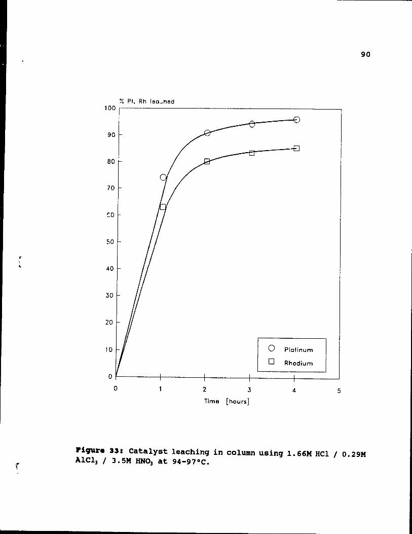
.. , ,
.... i
90
% Pt, Rh lee_ned 100~---------------------------------------------~
90
~ __ ---EJ
80
70
co
50
40
30
20
10 0 Pletinum
0 Rhodium
0
0 2 3 4 5
Time [hours]
l'iCJUr. 331 Catalyst leaching in column using 1.66M HCI / 0.2 9M Alel) / 3. SM lINO) at 94-97 oC •
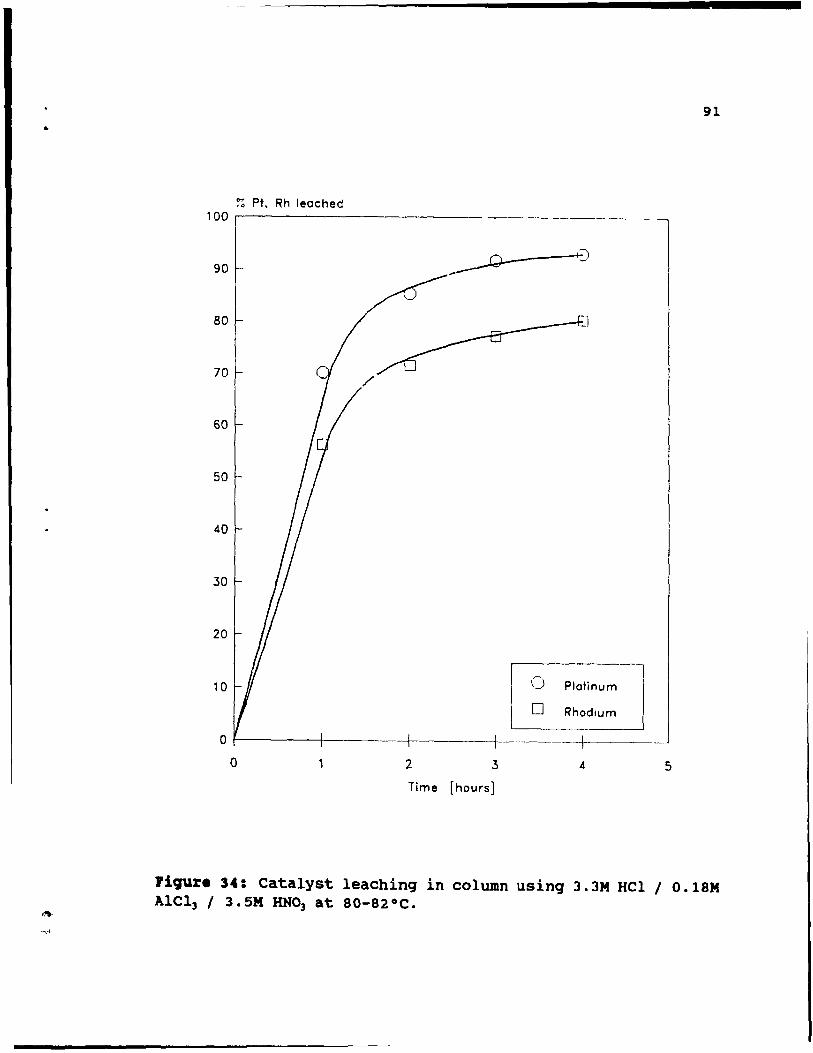
91
% Pt. Rh leached 100 ,..--------------- ------------
90
80
70
60
50
40
30
ligure 34: Catalyst leaching in column using 3.3M HCI / 0.18M AlCl) 1 3. SM HN03 at 80-82 oC.
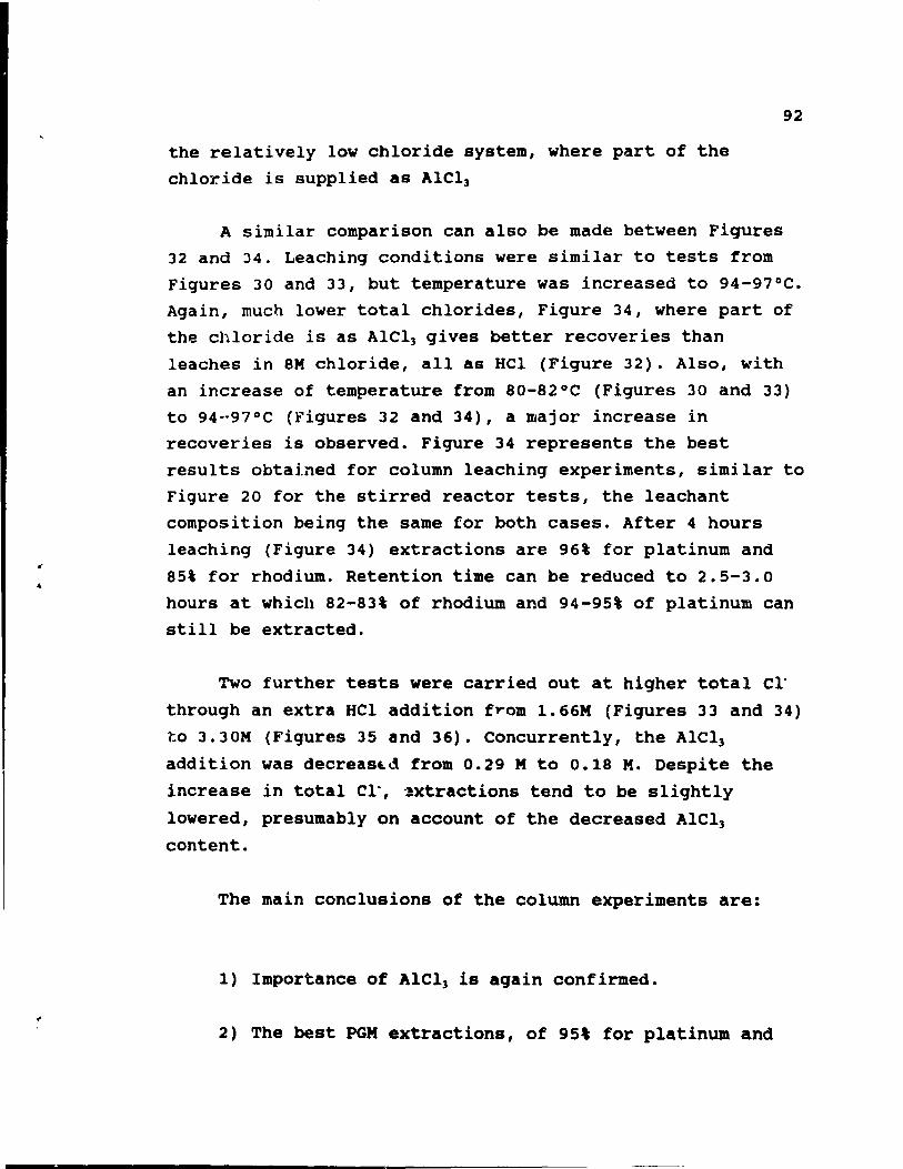
the relatively low chloride system, where part of the
chloride is supplied as AICl]
92
A similar comparison can also be made between Figures 32 and J4. Leaching conditions were similar to tests from
Figures 30 and 33, but temperature was increased to 94-97°C.
Again, mucn lower total chlorides, Figure 34, where part of
the chloride is as AICl] gives better recoveries than
leaches in 8M chloride, aIl as HCl (Figure 32). Also, with
an increase of temperature from 80-82°C (Figures 30 and 33) to 94·'97°C (Figures 32 and 34), a major increase in recoveries is observed. Figure 34 represents the best
results obtained for column leaching experiments, similar to
Figure 20 for the stirred reactor tests, the leachant
composition being the same for both cases. After 4 hours
leaching (Figure 34) extractions are 96% for platinum and
85\ for rhodium. Retention time can be reduced to 2.5-3.0
hours at which 82-83% of rhodium and 94-95% of platinum can still be extracted.
Two further tests were carried out at higher total Cl"
through an extra HCI addition from 1.66M (Figures 33 and 34)
to 3.30M (Figures 35 and 36). Concurrently, the AICI)
addition was decreas~d from 0.29 M to 0.18 M. Despite the
increase in total Cl', 3xtractions tend to be slightly
lowered, presumably on account of the decreased AICl]
content.
The main conclusions of the column experiments are:
1) Importance of Alel) ia again confirmed.
2) The best PGM extractions, of 95' for platinum and
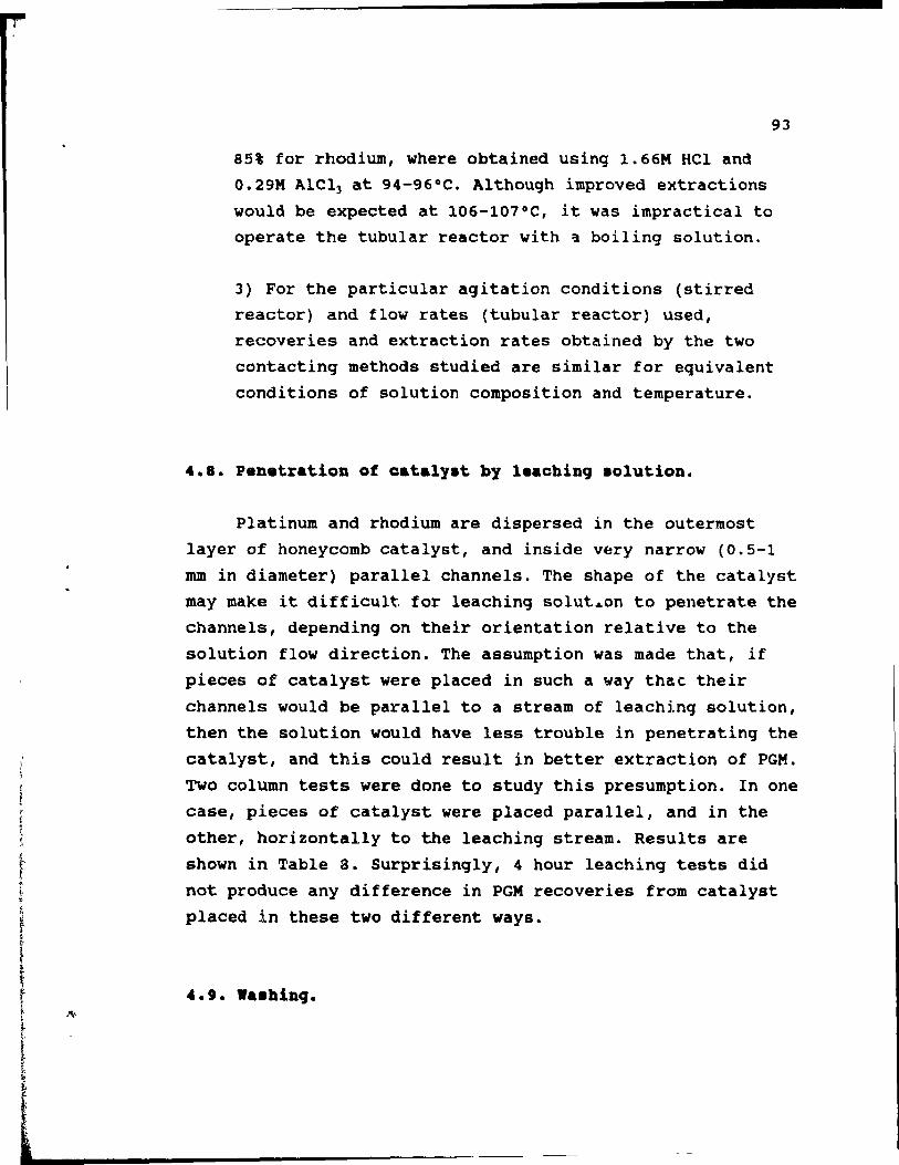
93
85% for rhodium, where obtained using 1.66M HCl and O.29M AlCl) at 94-96°C. Although improved extractions
would be expected at 106-107°C, it was impractical to operate the tubular reactor with a boiling solution.
3) For the particular agitation conditions (stirred reactor) and tlow rates (tubular reactor) used, recoveries and extraction rates obtained by the two
contacting methods studied are similar for equivalent
conditions of solution composition and temperature.
4.8. Penetration of catalyat by leaching aolution.
Platinum and rhodium are dispersed in the outermost
layer of honeycomb catalyst, and inside v~ry narrow (0.5-1
mm in diameter) parallel channels. The shape of the catalyst
may make it difficult. for leaching solutA.on to penetrate the channels, depending on their orientation relative to the
solution flow direction. The assumption was made that, if
pieces of catalyst were placed in such a way that their
channels would be parallel to a stream of leaching solution,
then the solution would have less trouble in penetrating the
catalyst, and this could result in better extraction of PGM.
Two column tests were done to study this presumption. In one case, pieces of catalyst were placed parallel, and in the
other, horizontally to the leaching stream. Results are
shown in Table a. Surprisingly, 4 hour leaching tests did
not produce any difference in PGM recoveries from catalyst
placed in these two different ways.
4.' •••• hing.
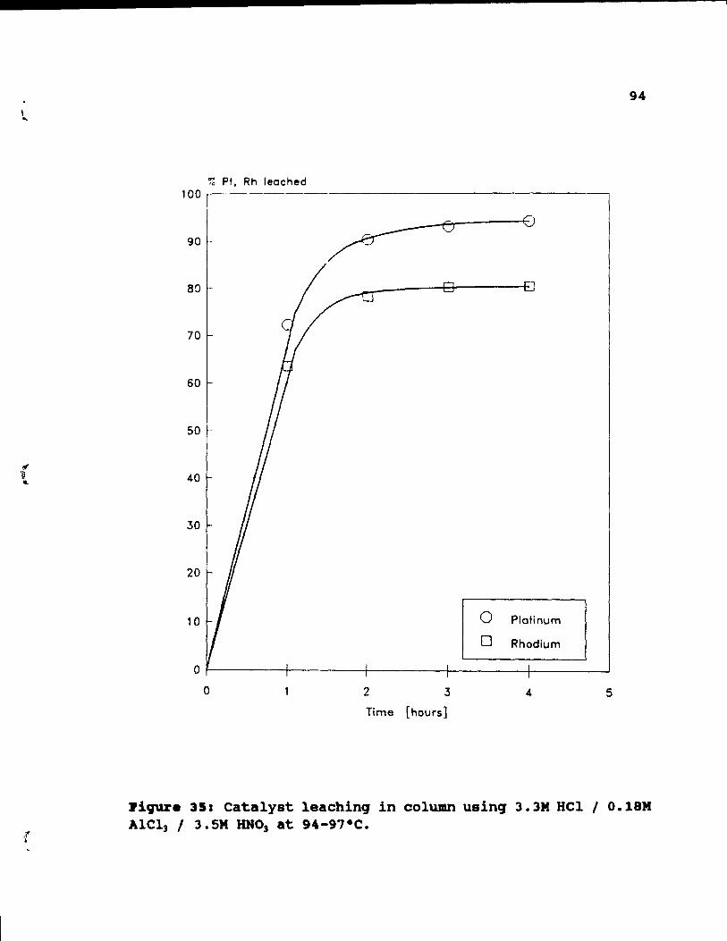
.\ ..
{
94
% Pt. Rh leached 100 ,--------------------------
90
8Q
70
60
50
40
30
20
10 0 Plotinum
0 Rhodium
0
0 2 3 4 5
Time [hours]
~iqur. 351 Catalyst leachinq in column usinq 3.3M Hel 1 O.18M A1Cl] 1 3.5M HNo] at 94-9"I·C.
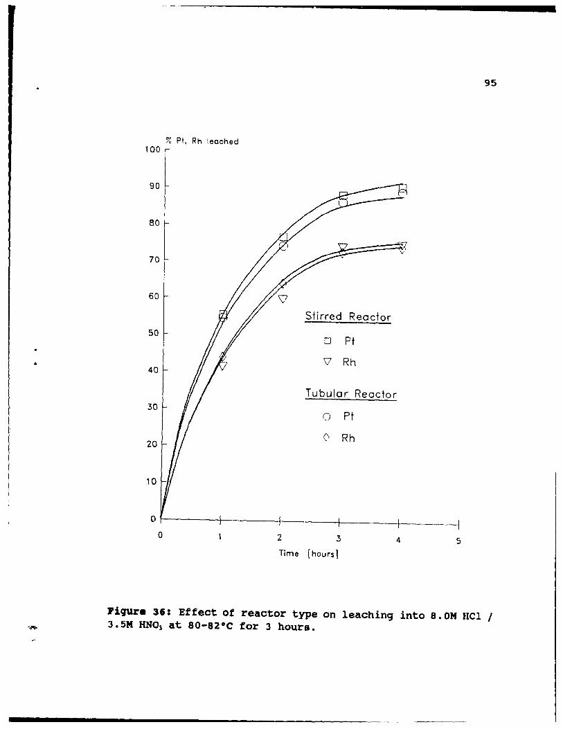
•
95
% Pt, Rh leached 100
90
80
ô7 >
V
70
60 ~ Stirred Reactor
50 0 Pt
V Rh 40
Tubular Reactor 30
0 Pt
20 0 Rh
10
o 1-----+----+----+-----l-------1 o 2 3 4 5
Time [heurs]
J'iqure 36: Effect of reactor type on leaching into 8. OM fIel 1 3.5M RNO) at 80-82·C for 3 hours.
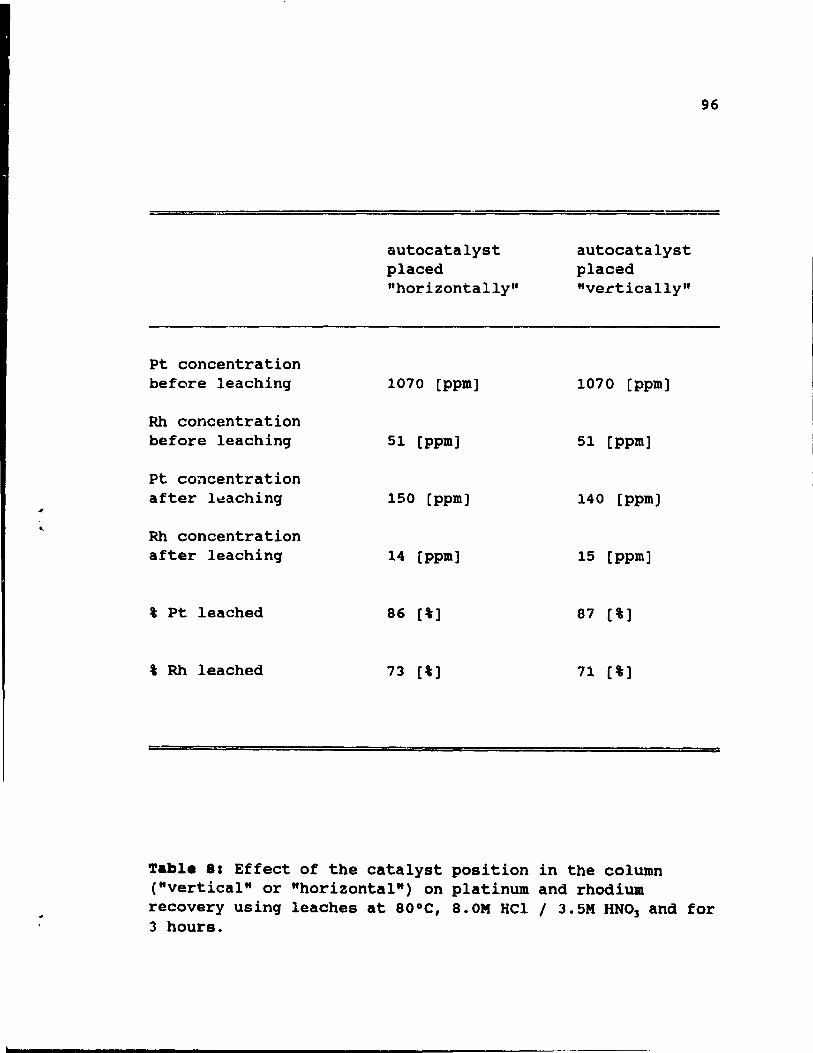
;r
..
Pt concentration before leaching
Rh concentration before leaching
Pt concentration after l\:!aching
Rh concentration after leaching
t Pt leached
t Rh leached
autocatalyst placed "horizontally"
1070 [ppm]
51 [ppm]
150 [ppm]
14 [ppm]
86 [t]
73 [t]
autocatalyst placed "ve.ctically"
1070 [ppm]
51 [ppm]
140 [ppm]
15 [ppm]
87 [t]
71 [i]
96
Table 81 Effect of the catalyst position in the column ("vertical" or "horizontal") on platinum and rhodium recovery using leaches at 80°C, 8.0M HCl 1 3.5M RNO] and for 3 hours.
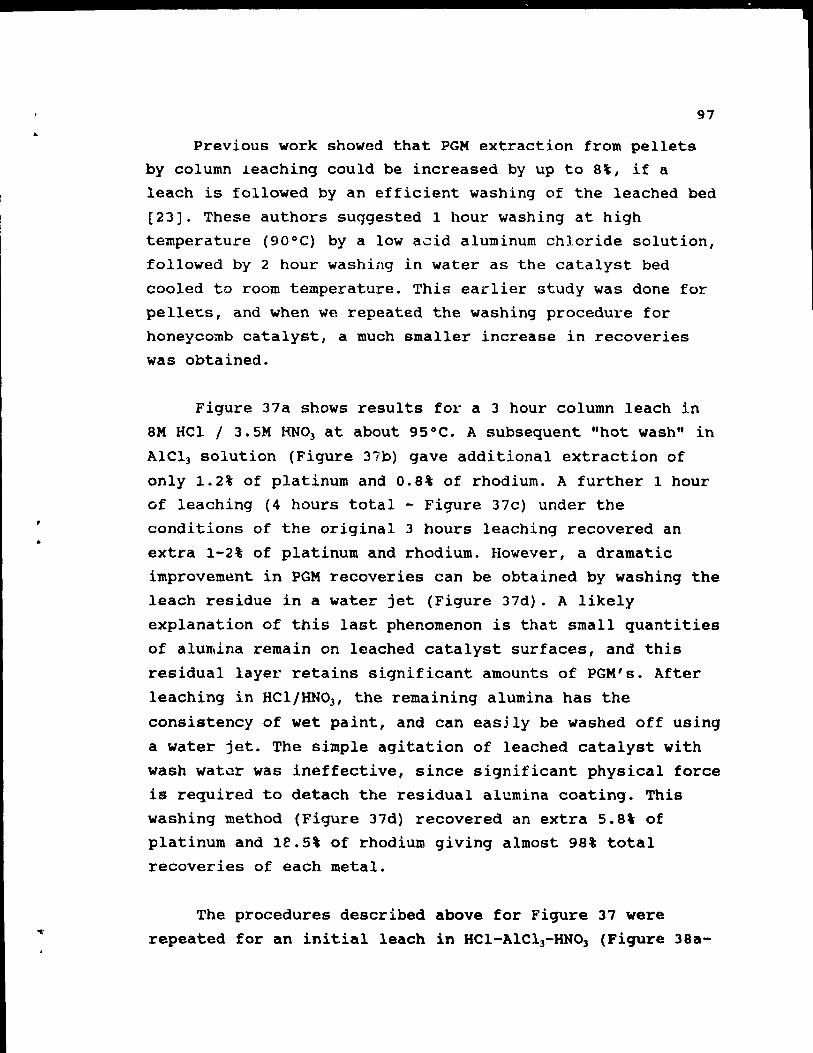
.. 97
Previous work showed that PGM extraction from pellets by column leaching could be increased by up to 8\, if a leach is followed by an efficient washing of the leached bed
(23). These authors suqgested 1 hour washing at high
temperature (90°C) by a low acid aluminum chloride solution, followed by 2 hour washing in water as the catalyst bed
cooled ta room temperature. This earlier study was do ne for
pelle~s, and when we repeated the washing procedure for honeycomb catalyst, a much smaller increase in recoveries
was obtained.
Figure 37a shows results for a 3 hour column leach in
8M HCI 1 3. SM RNO) at about 95°C. A subsequent "hot wash" in
AICl3 solution (Figure 37b) gave additional extraction of
only 1.2% of platinum and 0.8% of rhodium. A further 1 hour
of leaching (4 hours total - Figure 37c) under the conditions of the original 3 hours leaching recovered an
extra 1-2% of platinum and rhodium. However, a dramatic
improvement in PGM recoveries can be obtained by washing the
leach residue in a water jet (Figure 37d). A likely
explanation of this last phenomenon is that small quantities
of alu~ina rernain on leached catalyst surfaces, and this
residual layer retains significant amounts of PGM's. After
leaching in HCI/RN03 , the remaining alumina has the
consistency of wet paint, and can easjly be washed off using
a water jet. The simple agitation of leached catalyst with
wash wat~r was ineffective, since significant physical force
is required ta detach the residual alumina coating. This
washing method (Figure 37d) recovered an extra 5.8% of
platinum and 1e.5' of rhodium giving almost 98% total
recoveries of each metal.
The procedures described above for Figure 37 were
repeated for an initial leach in HCl-AlC13-HNOl (Figure 38a-
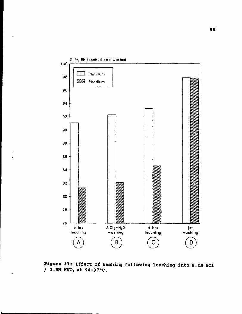
"'"
98
% Pt, Rh leached and washed 100
0 Platinum 98 - Rhodium
96
94
92
90
88
86
84
82
80
78
76 3 hrs AICI3+~O 4 hrs jet
leaching washing leaching washing
CF) ® @ ® ~igur. 37: Effect of washinq followinq leachinq into 8.0M HCI 1 3.5M HNO] at 94-97°C.
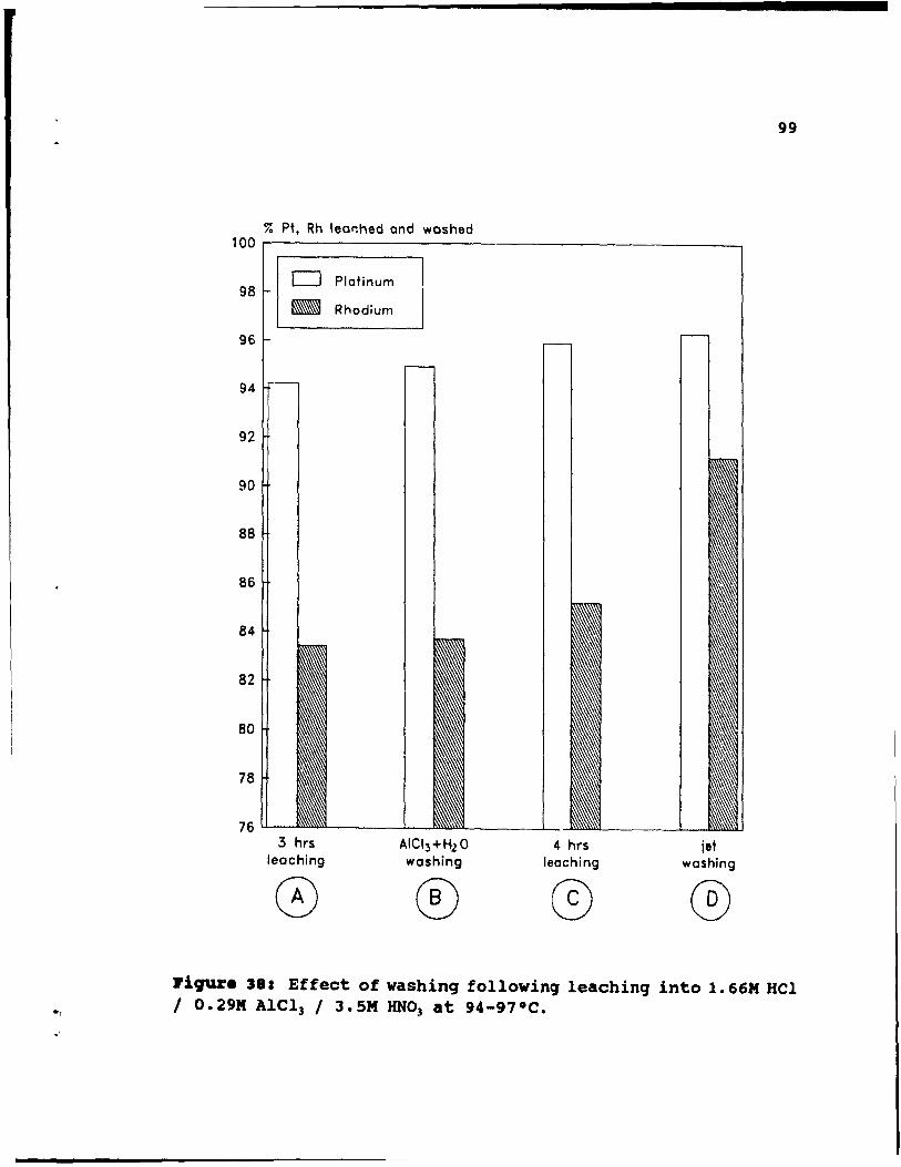
-, .'
% Pt. Rh lear:hed and washed 100r---------------------------------------------,
98
96
94
92
90
88
86
84
82
80
78
76
D Platinum
_ Rhodium
3 hrs leaching
o AICI 3 +HlO woshing
4 hrs leaching
jet woshing
®
99
Jli9'U'e 38: Effect of washinq followinq leachinq into 1. 66M HCl 1 O.29M Alel] / 3.5M HNO] at 94-97°C.
<f , ...
100
d) Here, the improvements shown by Figures 3Sb-d are less marked than in the equivalent experiments of Figure 37. This is because the initial leach (Figure 3Sa) gave higher recoveries than in Figure 37a. Also the alumina remaining on the leach residue is strongly adherent after a low acid AlCl) leach and is more difficult to remove by a water jet.
The practical operation of a water jet would require a specially designed vessel in which a minimum amount of water ia us.d to give a low volume sludqe which could be releached. It is probable that minor (1-3') amounts of PGM will remain trapped within internal channels of the catalyst and will not readily be recovered.
The above tests produced the following overall conclusions:
1. Aluminum chloride and water washing, used previously for pellets, produces only a smal'i. increase in recoveries when honeycombs are treated.
2. Jet washing dramatically improves PGM recoveries (up to 9S') followinq a "high" acid (S M HCI) leach, but this technique is less effective for a "low" acid leach with AICI) (1.66M HCI and 0.29M AICI).
4 .10 • • 8ti.atioll of Cl" activity.
Results shown in Figures 26 and 27 indicate, particularly at low HCI concentration, that platinum and rhodium recoveriea are dramatically improved when part of HCI leachant is replaced by AICI]. The chemistry of PGM
dissolution suggests that CI- ion activity (a~) plays a
decisive role to control the PGM dissolution.
The activity (a) of a completely dissociated electrolyte
C A t:t V CZ+ + vA"L-,+ po + -
101
(23)
is defined as the product of single ion activities (a+, aJ
or a mean activity (a±):
(2.'
The overall activity (a) of a pure solution, which conta in only one cation-anion pair is measurable, and much of the experimental data expressed as the mean activity
coefficient (y±) of strong electrolytes at various
concentrations in aqueous solutions, are available in the standard references [44]. The Debye-HUckel equation applies to these data below ionic strength (lm) 0.01, while severai other equations apply to hiqher concentrations (45).
Several experimenta1 data for mean activity coefficient
('Y±(.» in mixed electrolytes containing more thcln one
cation-anion pair (eg. HCl/AICI]) are also available [46]
[47]. To calculate the coefficients in other mixtures, a
simple empirical method proposed by Meissner and co-workers
is used [48] [49] [50].
Un1ike the overal1 activity (a), the single ion activity (a+l aJ is impossible to measure and its'
esti~ation is based on an ionic hydration theory formulated by Robinson and Stokes [51]. By using this theoretical approach, Bates and co-workers developed a method to
calculate single ion activities (a+ I aJ in unassociated chlorides [52]. Later, Jansz extended the method to estimate
the single ion activities (a+, aJ for mixed solutions [53].
He deve10ped equations for a solution containing both a
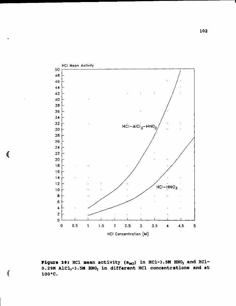
(
102
HCI Meon Activity 50
48
46
44
42
40
38
36
34
32
30
28
26
24
22
20
18
16
14
12
10
8
6
4
2
0 0 0.5 1 1.5 2 2.5 3 3.5 4 4.5 5
Hel Concentration [Ml
~iqur. 391 HCl mean activity (aHQ) in HCl-3.sM RNO, and HC1-0.29M A1C13-3. SM HN03 in differant HCl concentrations and at lOO·C.
•
•
103
univalent and a bivalent chloride. The estimation method for a more complex .lxture, containing more than two species, and especially a non-chloride one, is not yet developed.
4.11 ••• ti.ation of Bel •• an activity co.ffici.nt ••
To estimate mean activity coefficients ('YHCI(m» in HCI
HN03 and HCI-AICI3-HN03 solutions a method proposed by Kusik
and Meissner is used [50]. The calculations are shown in Appendix 1 and the final result of the calculations, HCI
mean activities in HCI-liNO) and HCI-AICI3-HN03 mixtures are
shown in Figure 39. It can be seen that for corresponding
HCI concentrations, addition of AICl3 raises the HCl
activities in the mixtures •
Although a quantitative estimation of Cl- single ion
activity (a~) in a complex solution is not yet available,
two facts can help to approximate activity values:
1. Cl- single ion activity coefficient ('Ye"> in our
mixtures may be considerably lower then the mean HCI
activity coefficient ('Yt<m». Several reports showed
that H+ single ion activity coefficient ('YH+)
considerably exceeds Cl- activity coefficient ('Y~) in
pure HCI or in mixed HCI-chloride solutions. In
mixtures up ta 6 M HCI, the Cl- activity coefficient
('Y~) remained relatively stable and equals 0.7 - 0.9 [53].
2. Accorcting to the hydration theory [51], cations with
high hydration numbers slightly increase anions
activities. It can be expected that the very
significant hydration number of AI3+, equals 31-33,
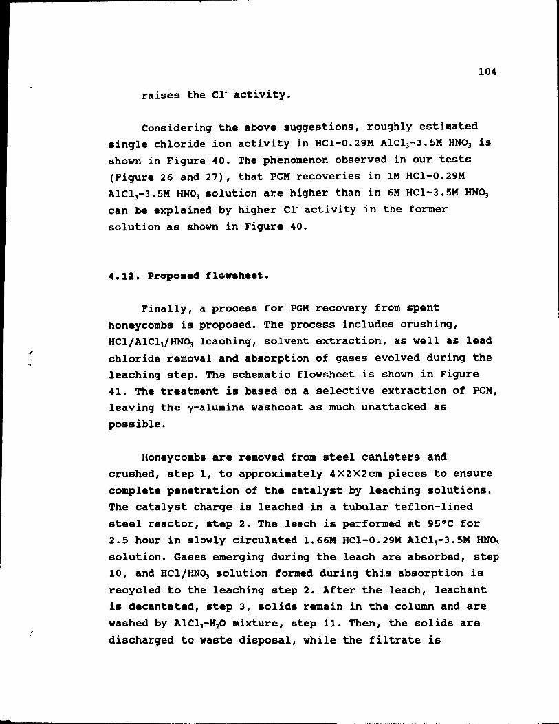
-
104
raises the Cl" acti vi ty.
Considering the above suggestions, roughly estimated single chloride ion activity in HCI-0.29M AICI3-J.5M HN03 is shown in Figure 40. The phenomenon observed in our tests (Figure 26 and 27), that PGM recoveries in lM HCI-O.29M AICI3-J.5M HNO] solution are higher than in 6M HCI-J. 5M HN03
can be explained by higher Cl" activity in the former
solution as shown in Figure 40.
4.12. Propo •• 4 fl~ •• h •• t.
Finally, a process for PGM recovery from spent honeycombs is proposed. The process includes crushing, HCI/AlCl]/HN03 leaching, solvent extraction, as weIl as lead
chloride removal and absorption of gases evolved during the leaching step. The schematic flowsheet is shown in Figure 41. The treatment is based on a selective extraction of PGM, leaving the l-alumina washcoat as much unattacked as possible.
Honeycombs are removed from steel canisters and crushed, step 1, to approximately 4X2X2cm pieces to ensure complete penetration of the catalyst by leaching solutions. The catalyst charge is leached in a tubular teflon-lined steel reactor, step 2. The leach is pe=formed at 95°C for 2.5 hour in slowly circulated 1.66M HCl-O.29M AICI3-J.5M HNO]
solution. Gases emerging during the leach are absorbed, step 10, and HCI/HN03 solution formed during this absorption is
recycled to the leaching step 2. After the leach, leachant is decantated, step 3, solids remain in the column and are washed by AICl3-H20 mixture, step 11. Then, the solids are
discharged to waste disposaI, while the filtrate i5
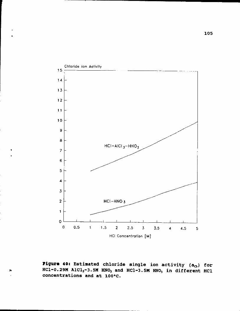
..
"
105
Chloride Ion Activity 15 ,------------------------ ----------
14
13
12
1 1
10
9
8
7
6
5
4
3
2
o 0.5 1.5 2 2.5 3 3.5 4 4.5 5
HCI Concentration [M]
l'iqure 40: Estimated chloride sinqle ion activity (acd for HCI-0.29M AIC13-J.5M RNO] and HCI-J.5M RNO] in different HCl concentrations and at lOO·C.
(
(
106
HONEYCOMBS
Hel + HNOJ recyc"
sonds
• SOl/d'!0
PbCI;ïL. \\:::J-= __ -.-___ -'
Sol/ds
.,osl. disposai
Slrlpplng og.nl ...--__ ----'L-__ ---,
,..cycl.
l'iCJUr. 41: Proposed flowsheet of PGM recovery from spent autocatalyst by an aluminum chloride leach process.
&
107
transferred back ta the absorbtion step 10. Pregnant solution from step 3 is allowed to cool and PbC12 is
crystallized, step 4. Next, the solution is decantated, step S, and PbC12 removed. To separate PGM from leach liquor,
solvent extraction with Kelex 100 or Lix 26 is performed,
step 6. Aqueous phase is recycled to chloride leaching step
2. The recycling prevents potential PGM losses. A stripping step, step 7 and precipitation, step 8, are used to separa te ?GM from impurities. Finally, the slurry is filtered, step
9, and PGM concentrate transferred for further treatment. Extractant and stripping agent are recycled.
CBAPTD 51 CO_CLU.IO_.
5.1. contri~ution to original knovl.4q ••
The following should be considered contributions to
original knowledge:
1. Detailed research study on rhodium recovery from spent autocatalyst by HCII AICl)/HNO) and HCI/UNO]
leaches.
2. Optimization of HCI/AICl)/HNO) leaching of spent autocatalyst. The optimization includes:
- CI- concentration and AICI)/HCI ratio in the
leachant - temperature of the process - HNo) concentration in leaching solution - retention time of leaching - qrindinq of the feed.
3. Comparative study on different types of leachinq reactors (stirred and tubular) used in this process.
108
1. Fast extraction ot platinum and rhodium trom spent honeycomb-type catalyst with HCI/AICI)/HNO) or HCI/UNO)
solutions has been obtained. The results show the followinq advantaqes of HCI/AIC13/HN03 over HCI/HN03
leachinq.
1. Unlike HCI/UNO)I the HCI/AIC13/HN03 leachinq
109
does not require highly concentrated solutions, because relatively low AlCI) and HCI levels assure
good PGM extractions.
2. The HCI/AICI]/HNO] system is much easier to work
with, because of less fumes and Iess corrosive medium than HCI-HNO) at equivalent Cl" levels.
II. Experimental data allowed definition of optimum
conditions of the HCl/AlCI]/HNO] leaching process.
1. The PGM extraction should be performed at a low level of HCI, but a relatively high AICI]/HCI
ratio. Increasing AICI] concentration tends to
increase rhodium recovery, while that of platinum remains unchanged. The highest recoveries were
obtained for 1.66M HCI-O.29M AICI)-3.5M HNO].
2. Temperature was found to be one of the most important variables and leaching performed at less than SOOC is ineffective. 90-95°C is recommended
to keep retention time reiatively short, around
2.5 hours.
3. Leachinq without oxidant (in this case HNO]) or
in small concentrations of the oxidant results in weak PGM extraction. To ontain good recoveries, tbe initial concentration of HNO) should ne
maintained at not less than 3M.
4. A jet washing step significantly improves PGM recoveries, but this is difficult to perform effectively.
110
III. Recoveries and extraction rates obtained by the two contacting methods studied, stirred and tubular reactors, are similar for equivalent conditions of solution composition and temperature. This suggests the use of a tubular type reactor, which gives solutions
more concentrated in platinum and rhodium and avoids a solid/liquid separation step. A possibility of higher PGM recoveries by using a finely ground feed, a
potential advantage of stirred reactor leaching, was not demonstrated in the case of honeycomb-type
catalyst. The results showed that grinding is not necessary, and breaking honeycombs into 4X2X2cm pieces assures good penetration of catalyst channels by leachants. This means that, in this case, a batch type reactor has no advantage over the column type vessel.
The transfer of experimental data from a lao-scale column to a small industrial installation is acceptable from an engineering point of view, because both reactors are operating under similar conditions.
IV. The results suggest t.hat cr single ion activity plays
a decisive role to control PGM dissolution. The very
qood performance of HCI/AICI3/HN03 can be explained by the high hydration number of Al +3 which raises the cr activity.
v. The presented method ia effective and inexpensive, and can be very attractive and highly competitive as compared to actually operating pyrometallurgical
methods. A considerable advantage of this method ia the
111
possibility of building and operating a small (5-20 tonnes of cataly~t/day) and inexpensive installation.
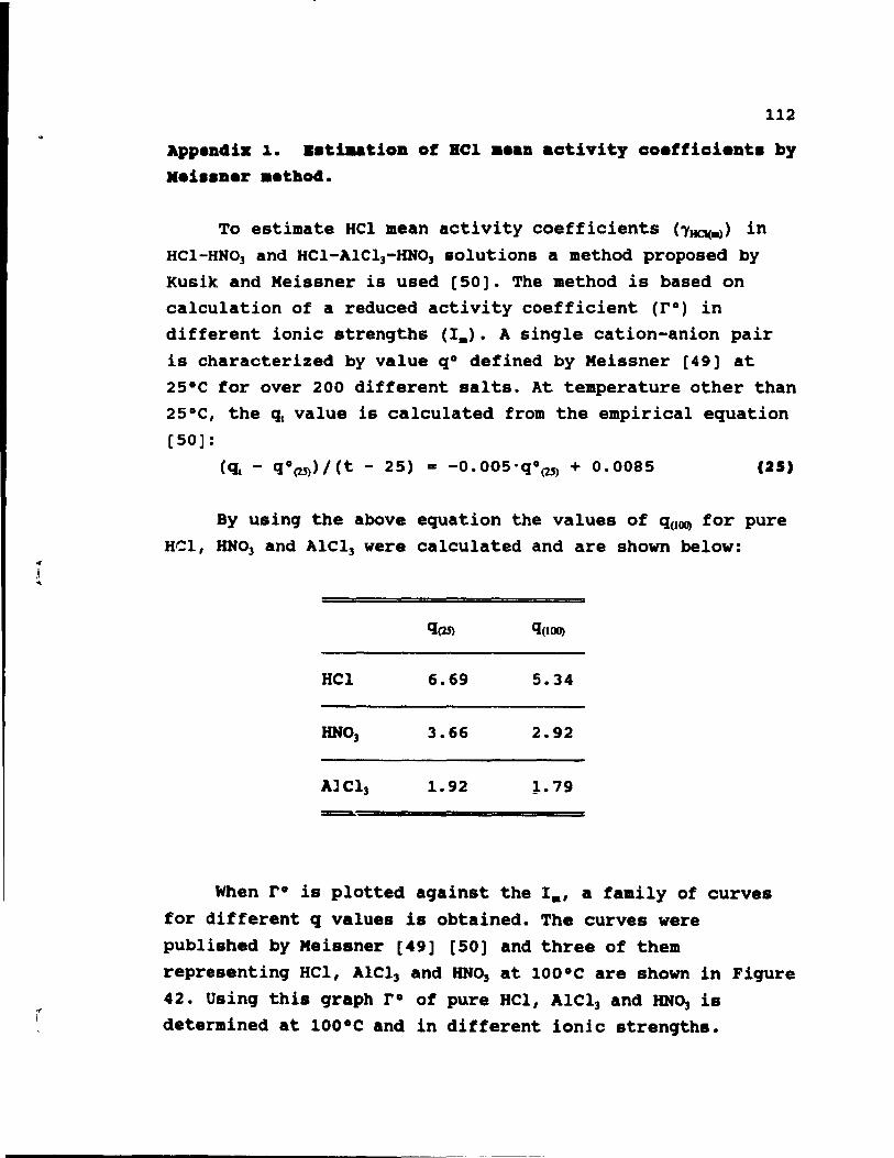
~
,1 ...
112
App.ndiz 1. ..tiaatiOD of BCI •• an activity coefficient. by .ei •• Der .etbod.
To estimate HCI aean activity coefficients (1~~) in HCI-HNO, and HCI-AICI)-HNOJ solutions a method proposed by Kusik and Meissner is used [50]. The method is based on calculation of a reduced activity coefficient (rO) in different ionic strenqths (1.). A sinqle cation-anion pair is characterized by value qO defined by Meissner [49] at 25°C for over 200 different salts. At temperature other than 25°C, the qt value is calculated from the empirical equation [50]:
(q, - q°(25)/Ct - 25) = -0.005·q°(2j) + 0.0085 (25)
By usinq the above equation the values of q(lOO) for pure HCI, HNO, and AICI, were calculated and are shown below:
q(25) q(lOO)
HCI 6.69 5.34
HNO, 3.66 2.92
AlCI) 1.92 }..79 -===a.:
When ro is plotted aqainst the 1., a family of curves
for different q values i. obtained. The curves were published by Meissner [49] [50] and three of them representinq HCI, AICI, and HNO, at 100·C are shown in Fiqure 42. Usinq thi. qraph r· of pure HCI, AICl) and lINO) is determined at 100·C and in different ionic strenqths.
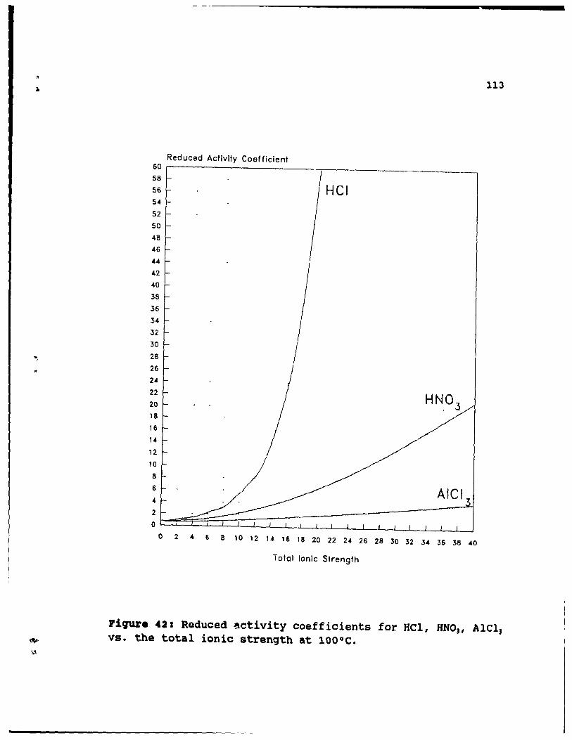
"
",
"
113
60 Redueed Activity Coefficient
58
56 Hel 54
52
50
48
46
44
42
40
38
36
34
32
30
28
26
24
22
20
18
16
14
12
10
8
6
4 Alel 2
0
o 2 4 6 8 10 12 14 16 18 20 22 24 26 28 30 32 34 36 38 40
Total Ionie Strength
Pigure 42: Reduced ~ctivity coefficients for HC1, KNO]I A1Cl] vs. the total ionic strength at 1000C.
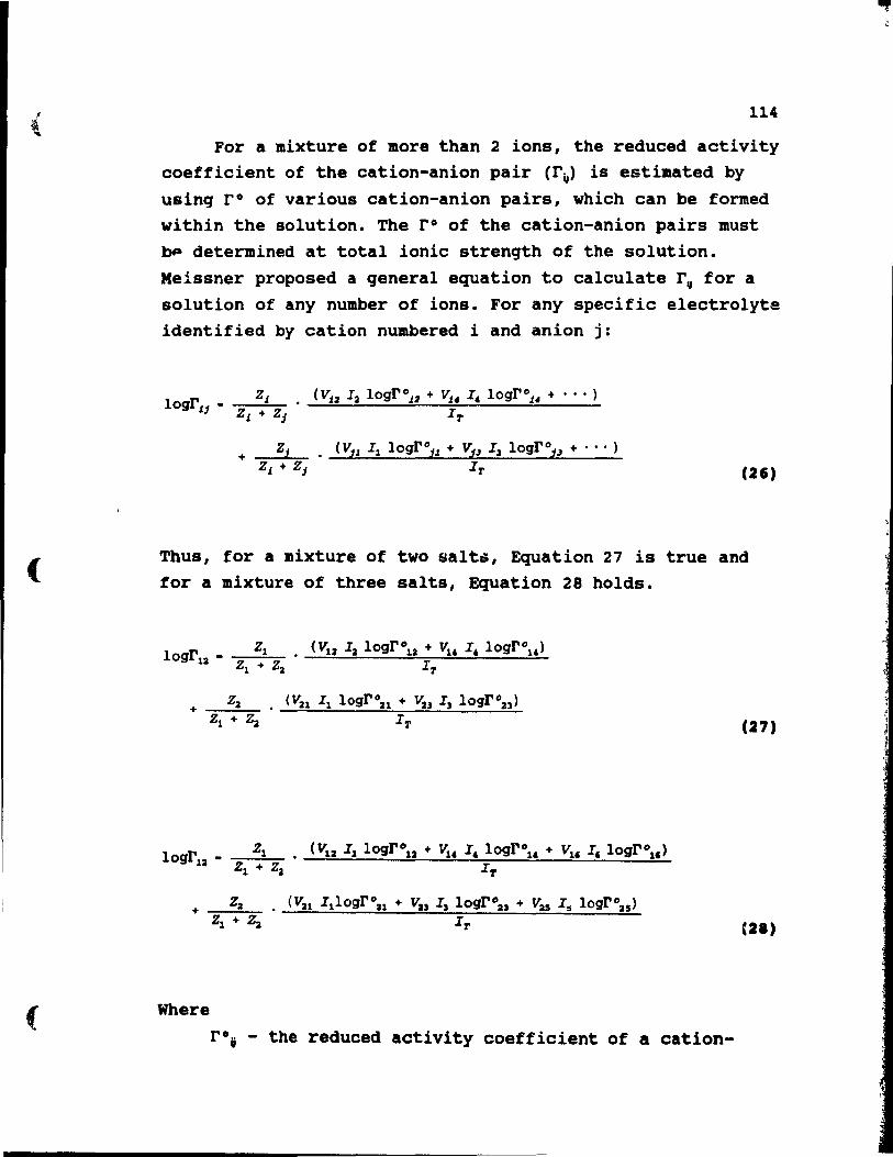
(
(
114
For a mixture of more than 2 ions, the reduced activity coefficient of the cation-anion pair (rv> is estimated by using ro of various cation-anion pairs, which can be formed within the solution. The r o of the cation-anion pairs must bp determined at total ionic strength of the solution. Meissner proposed a general equation to calculate r, for a solution of any number of ions. For any specifie electrolyte identified by cation numbered i and anion j:
(V.t:l Ia logr°.t:l + Vu I, logr°.14 + ••• )
IT
(Vil Il logrOil + Vi) I3 logroi.J + ••• )
IT (26)
Thus, for a mixture of two salt~, Equation 27 is true and for a mixture of three salts, Equation 28 holds.
Where
(Vu Il logr021 + Va3 I3 logr023 )
IT
(Vu IllogrOu + Vu I3 logroa;s + vas I,. logrOzs )
If'
rOt - the reduced activity coefficient of a cation-
(27)
(21)
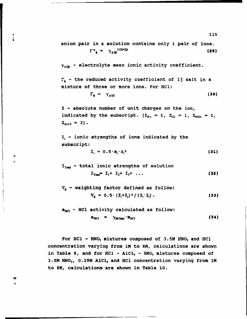
.. l
115
anion pair in a solution contains only 1 pair of ions. (29)
~%~ - electrolyte mean ionic activity coefficient.
r, - the reduced activity coefficient of ij salt in a mixture of three or more ions. For Hel:
(30)
Z - absolute number of unit charges on the ion, indicated by the subscr ipt. (ZH+ = 1, Za- = 1, ZN03- = 1,
ZAI+3 = 3).
1. - ionic strengths of ions indicated by the subscript:
ITœd - total ionic strengths of solution
I Tœd= 11+ I 2+ I3+ •••
Vij - weiqhtinq factor defined as follow:
Vij = 0.5· (Z.+Z,}2 1 (Zj· Zj) •
aHCI - HCl activity calculated as follow:
aHCI =
(31)
(32)
(33)
(34)
For HCl - HN03 mixtures composed of 3. SM HN03 and HCl concentration varying from lM to 8M, calculations are shown in Table 9, and for HCl - AlCl3 - HN03 mixtures composed of 3.5M RN03 , 0.29M AlCl] and HCl concentration varying from lM
to 8M, calculations are shown in Table 10.
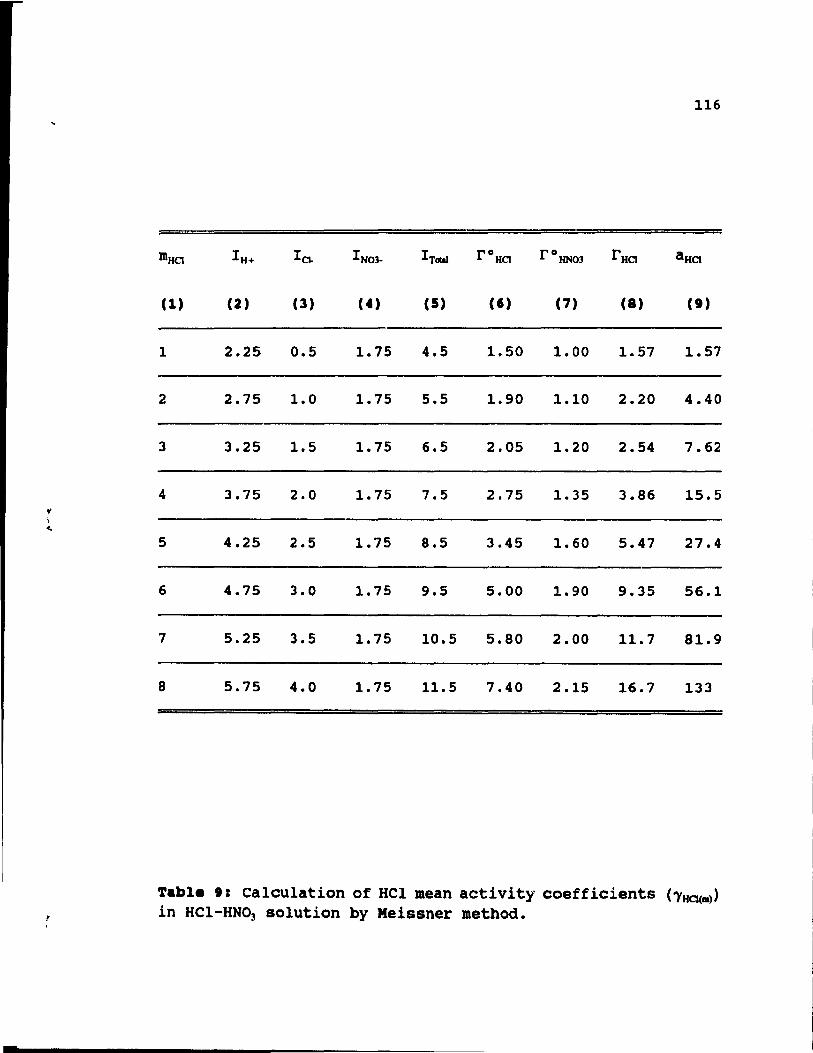
l' \ ~
, ,
116
mHa IH+ ICI- I N03- ITaIaI rO Ha rO HN03 rHa aBa
(1) (2) (3) (4) (5) Ct) (7) (8) (1)
1 2.25 0.5 1. 75 4.5 1.50 1.00 1.57 1.57
2 2.75 1.0 1. 75 5.5 1.90 1.10 2.20 4.40
3 3.25 1.5 1. 75 6.5 2.05 1.20 2.54 7.62
4 3.75 2.0 1. 75 7.5 2.75 1.35 3.86 15.5
5 4.25 2.5 1. 75 8.5 3.45 1.60 5.47 27.4
6 4.75 3.0 1. 75 9.5 5.00 1.90 9.35 56.1
7 5.25 3.5 1. 75 10.5 5.80 2.00 11. 7 81.9
8 5.75 4.0 1. 75 11.5 7.40 2.15 16.7 133
Table 1: Calculation of HCI mean activity coefficients ('YHO(81» in HCI-HN03 solution by Meissner method.
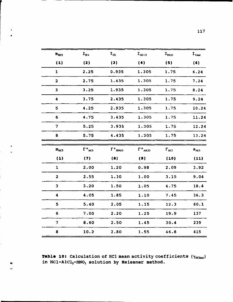
117
m Ha IH+ la. I AI+3 I NO)_ ITCUI
(1) (2) (3) (4) (5) (1)
1 2.25 0.935 1.305 1. 75 6.24
2 2.75 1.435 1. 305 1. 75 7.24
3 3.25 1.935 1.305 1. 75 8.24
4 3.75 2.435 1. 305 1. 75 9.24
5 4.25 2.935 1.305 1.75 10.24
6 4.75 3.435 1.305 1. 75 11.24
7 5.25 3.935 1.305 1. 75 12.24
8 5.75 4.435 1. 305 1. 75 13.24
m Ha rORa rO HN03 r ° AICI3 r RCJ aRa
(1) (7) (8) (t) (10) (11)
1 2.00 1.20 0.98 2.09 3.92
2 2.55 1. 30 1.00 3.15 9.04
3 3.20 1.50 1.05 4.75 18.4
4 4.05 1.85 1.10 7.45 36.3
5 5.40 2.05 1.15 12.3 60.1
6 7.00 2.20 1.25 19.9 137
7 8.60 2.50 1. 45 30.4 239
8 10.2 2.80 1.55 46.8 415
Table 10: Calculation of HCl mean acti vi ty coeff icients ('YHCI(Dl») in HCI-AIC13-HN03 solution by Meissner method.
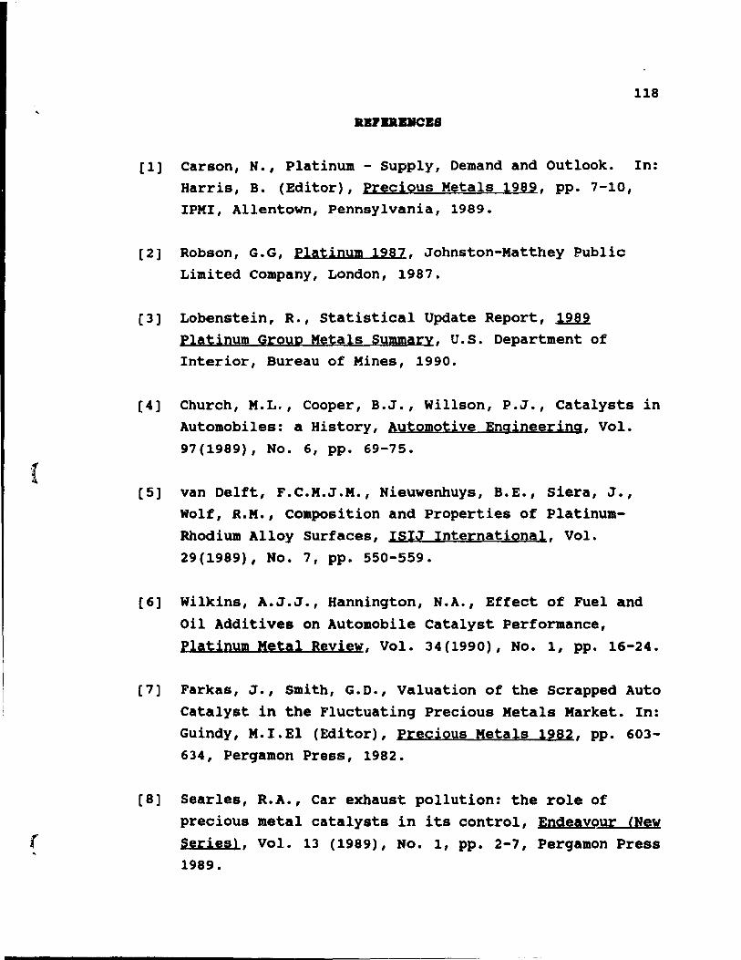
(
118
.BPBRBMCB8
[1] Carson, N., Platinum - Supply, Demand and Outlook. In: Harris, B. (Editor), precious Metals 1989, pp. 7-10, IPHI, Allentown, Pennsylvania, 1989.
[2] Robson, G.G, PIAtinum 1987, Johnston-Matthey Public Limited company, London, 1987.
[3] Lobenstein, R., statistical Update Report, ~ Platinum Group Metals Summary, U.S. Department of Interior, Bureau of Mines, 1990.
[4] Church, M.L., Cooper, B.J., Willson, P.J., Catalysts in Automobiles: a History, Automotive Engineering, Vol. 97(1989), No. 6, pp. 69-75.
[5] van Delft, F.C.M.J.M., Nieuwenhuys, B.E., Siera, J., Wolf, R.M., composition and Properties of PlatinumRhodium Alloy Surfaces, ISIJ International, Vol. 29(1989), No. 7, pp. 550-559.
[6] Wilkins, A.J.J., Hannington, N.A., Effect of Fuel and oil Additives on Automobile Catalyst Performance, Platinum Metal Reyiew, Vol. 34(1990), No. l, pp. 16-24.
[7] Farkas, J., Smith, G.D., Valuation of the Scrapped Auto Catalyst in the Fluctuating precious Metals Market. In: Guindy, M.I.El (Editor), precious Metals 1982, pp. 603-634, pergamon Press, 1982.
[8] Searles, R.A., Car exhaust pollution: the raIe of precious metal catalysts in its control, Endeavour CNew Series), Vol. 13 (1989), No. l, pp. 2-7, pergamon Press 1989.
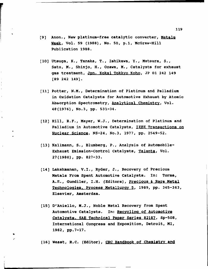
[9) Anon., New platinum-free catalytic converter, Metals ~, Vol. 59 (1988), No. 50, p.1, McGraw-Hill PUblication 1988.
119
[10] utsuga, K., Tanaka, T., Ishikawa, Y., Matsura, S., Sato, M., Shinjo, H., Ozawa, M., Catalysts for exhaust gas treatment, Jpn. Kokai TokkyQ Koho, JP 01 242 149 [89 242 149).
[11] Potter, N.M., Determination of P1atinum and Palladium in Oxidation Catalysts for Automotive Exhaust by Atomic Ab$orption Spectrometry, Analytical Chemist~, Vol. 4e(1976), No.3, pp. 531-34.
[12] Hill, R.F., Mayer, W.J., Determination of Platinum and Palladium in Automotive Catalysts, IEEE Transactions on Nuclear Science, NS-24, No.3, 1977, pp. 2549-52.
(13] Kallmann, S., Blumberg, P., Analysis of AutomobileExhaust Emission-control catalysts, Talanta, Vol. 27(1980), pp. 827-33.
[14] Lakshmanan, V.I., Ryder, J., Recovery of Precious Metals From Spent Automotive catalysts. In: Torma, A.E., Gundiler, I.H. (Editors), precious , Rare Metal Technologies. Process Metallurgy 5, 1989, pp. 345-363, Elsevier, Amsterdam.
[15] D'Aniello, M.J., Noble Metal Recovery from Spent Automotive Catalysts. In: Recycling of Automotive Catalysts. SAE Technical PAper Series 82187, Sp-508, International Congress and Exposition, Detroit, MI, 1982, pp.7-17.
[16] Weast, R.C. (Editor), CRC Handbook of Chemistry and
=
.,. 1 ...
pbysies, 69th Edition, CRe Press, 1988.
[17] Bradford, C.W., Baldwin, S.G., Recovery of Precious Metals From Exhaust eatalysts, Brit. Pat. 1 517 270, May 1975. US Pat. 3 985 954.
120
[18] Bonueei, J.A., Parker, P.O., Recovery of PGM from Automobile eatalytic Converters, Proc. AIME-If MI precious Metals Symp •. Loa Angeles, 1984, pp. 465-481.
[19] Bautista, R.G., Yue, L., Tyson, D.R., Platinum and Palladium Reeovery from Spent Automotive Catalysta, Leachinq with (HC1):(HN03) in a Packed and Fluidized Bed. In: Torma, A.E., Gundiler, I.H. (Editors), precious , Rare Metal Technologies, Process Metallurgy 2, 1989, pp. 345-363 Elsevier, Amsterdam •
[20] M~8hra, R.K., Recovery of Platinum Group Metala from Automobile eatalytic Converters - A Review. In: Jha, M.C., Hill, S.D. (Editora), Precious Metals 1989, The MineraIs, Metals , Materials Society, 1988, pp.483-501.
[21] Hoffmann, J.E., Recovery of Platinum Group Metals from Automotive catalysts. In: Torme, A.E., Gundiler, I.H. (Editora), precious , Rare Metal Technologies. Process Metallursy. ,2, 1989, pp. 345-363, Elaevier, Amsterdam.,
[22] Lakshmanan, V.I., Todd, I.A., Ryder, J., Zamora, M.J., Recovery of Platinum and Palladium from Spent Automotive catalysta. In: Harris, B. (Editor), precioua Metala 191i, pp. 237-242, IPMI, Allentown, Pennsylvania, 1989.
[23] Letowaki, F.K., Distin, P.A., Platinum and Palladium
1
Recovery trom Spent Catalysts by Aluminum Chloride Leaching. In: Proc. Int. Sympa on Recycle and Secondary Recovery of Metals, Fort Lauderdale, AIME, 1985, pp. 735-45.
121
[24] Letowski, F.K., Distin, P.A., Platinum and Palladium Recovery trom Scrapped Catalytic Converters by a Chloride Leach Route - Laboratory Results and pilot Plant Design. In: Davies, G.A. (Editor), Separation Processes in Hydrometallurgy, pp. 68-76, Soc. Chemical Industry, London, UK, 1987.
(25] Tyson, D.R., Bautista, R.G., Leaching Kinetics of Platinum and Palladium from Spent Automotive Catalysts, Separation Science and Technology, Vol. 22 (1987), pp. 1149-67.
(26] Hoffmann, J.E., Recovering platinum-Group Metals from Auto Catalysts, Journal of Metals, (1988), No. 6, pp. 40-44.
[27] Letowski, F.K., Distin, P.A., Development of Aluminum Chloride Leach Process for Platinum and Palladium Recovery from Scrapped Automotive Catalysts. In: Harris, B. (Editor), precious Metals 1989, pp. 41-49, IPMI, Allentown, Pennsylvania, 1989.
[28] Keyworth, 8., The role of pyrometaliurgy in the recovery of precious Metals from secondary materiais. In: Guindy, M.I.El (Editor), precious Metals 1982, pp. 509-537, pergamon Press, 1982.
[29] Mishra, R.K., Reddy, R.G., pyrometallurgical processing and Recovery of precious Metais from Autocatalysts Usinq Plasma Arc Smelting. In: Rao, U.V. (Editor),
(
(
precious Metals 1986, pp. 237-46, IPMI, Lake Tahoe, Nevada, 1986.
[30] Boke, C.M., More, J., Solution of Platinum in Aqua Regia, The Metal Industry, Vol. 14(1916), No. 7, pp. 296-8.
122
[31] Privoznik, E., Über Konigswasser, Osterreichische zeitschrift fUr Berg- und HUttenwesen, Vol. 57(1910),
No. 39, pp. 549-50.
[32] Moore, W.C., Aqua Regia, The Effect of Chloride Ion on the Potential of the Nitric Acid Electrode, J. Am. Chem. Society, Vol. 35(1913), pp. 333-340.
[33] Briner, E., Sur le mecanisme des reactions dans l'eau regale, comptes rendus, Vol 162 (1916), pp. 387-89.
[34] Briner, E., Heberlein, R., Rothen, A., Sur la conductibilite de l'eau regale stabilisee, Helv. Chim. A&tA, Vol. 9(1926), pp. 951-56.
[35] Oishi, Y., The oxidation reaction by nitric acid; Equilibrium of the system HCl-HN03-H20, Journal of the
~emical Society of Japon. Industrial Çhemistry section, Vol. 53(1950), pp. 418-20 (Jap.).
[36] Fleury, P., Oxydation of platinum and gold byaqua regia, Bulletin de l'Union des Physiciens, Vol. 72/606
(1978), pp. 1349-52 (Fr.).
[37] Wolcott, E., Process for Recovering Valuable Rare Metals by Vol~tilization, US Patent, 1959, No. 3 049
422.
123
[38) stern, E.W., Aqueous Chemistry of precious Metals Applicable to Refining Processes. In: Foo, G.,
Browning, M.E. (Editors), Second Symposium on Recovery,
Reclamation and Refining of precious Metals, San Diego, CA, IPMI PUblications, 1981.
[39] Goldberg, R.N., Hepler, L.G., Thermochemistryand
Oxidation Potentials of the Platinum Group Metals and
Their Compounds, Chem. Rey., Vol. 68(1968), pp. 229.
[40) Langford, C.H., Gray, H.B., Ligand Substitution
Processes, W.A.Benjamin Inc., 1966.
[41) Potter, N.M., Waldo, R.A., Determination of Platinum in Alumina-Supported Automotive Catalyst Material by Electrothermal Atomic Absorption Spectrometry,
Analytical Chimica Acta, Vol. 110(1979), pp. 29-34.
[42] Powell, B.R., Chen, Y., Analytical electron microscopy of a vehicle-aged automobile catalyst, Applied
Catalysis, Vol. 53(1989), No. 2-3, pp. 233-250.
[43] Hepburn, J.S., stenger, H.G., Lyman, C.E., Distribution
of HF Co-impregnated Rhodium, Platinum and Palladium in
Alumina Honeycomb Supports, Applied Catalysis, Vol. 55
(1989), No. 3, pp. 271-285.
[44] RObinson, R.A. (Editor), Eguilibrium properties of
electrolyte solutions. In: Eley, 0.0., Mayer, J.E.,
Tompkins, F.C. (Editors), The International
Encyclopedia of Physical Chemistry and Chemical Physics, Topic 15, pergamon Press, 1968.
[45] Horvat, A.L., Handbook of Aqueous Electrolyte
.
Solutions. Physical prQperties. Estimatian and Correlation Methods, pp. 206-232.
124
[46] Harned, H.S., Gary, R., The Activity Coefficient of Hydrochloric Acid in Concentrated Aqueous Higher Valence Type Chloride Solutions at 25°Ci the System Hydrochloric Acid - Aluminum Chloride. Journal of the American Chemical Society, Vol. 77(1955), No. 18, pp. 4695-97.
[47] Harned, H.S., Mason, C.M., The Activity Coefficient of Hydrochloric Acid in Aluminum Chloride Solutions. Journal of the American Chemical Society, Vol. 53(1931), pp. 3377-3380.
[48] Meissner, H.P., Jefferson, W.T., Activity Coefficiens of Strong Electrolytes in Aqueous Solution, Ind. Enq. Chem. Procesa Des. Develop., Vol. 11(1972), No. 1, pp. 128-133.
[49] Meissner H.P., Prediction of Activity Coefficients of Strong Electrolytes in Aqueous Systems, AIChE Journal, Vol. 26(1980), pp. 495-512.
[50] Kusik C.L., Meissner H.P., Electrolyte Activity Coefficients in Inorganic Processing, Fundamental Aspects of Hydrometallurqical Processes, AIChE Symposium Series, Vol. 74(1978), No.173, pp. 14-20.
[51] RObinson, R.A., Stokes, R.H., Electrolyte Solutions, Butterworths, 1959.
[52] Bates, R.G., Staples, B.R., Robinson, R.A., Ionie Hydration and Single Ion Activities in Unassociated Chlorides at High Ionie Strenghts. Analytical
Chemistry, Vol. 42(1970), No. 8, pp. 867-871.
[53) Jansz, J.J.C., Thermodynamies of Aqueous Chloride Solutions: Calculation of Ionie Activities and Distribution Data for Chlorocomplexes, TMS Paper Selection, Paper No. A84-1, 1984.
[54) Edward, R.I., Riele, W.A.M., Handbook of Solvent Extraction, T.Lo.M.H.I. and C. Hanson Eds., Wiley
Interscienee, pp. 725-732, 1983.
125
[55] Flett, O.S., Hydrometallurgy: Research, Development and
Plant Praetiee. In: Osseo-Asare, K., Miller, J.O.
(Editors), TMS-AIME, 1983, pp. 39-64.