Embed Size (px)
Citation preview
DOUBLE WALL INSULATED CHIMNEY SYSTEMS“THE COOLEST UNDER THE HOTTEST CONDITIONS...”
C ATA L O G
CHIMNEY SYSTEMSULTRA-TEMP® HT - Tested up to 2100˚Stainless Steel
ULTRA-TEMP® - Tested up to 1700˚Stainless Steel
GALVA-TEMP® HT - Tested up to 2100˚Galvanized Outer
GALVA-TEMP® - Tested up to 1700˚Galvanized Outer
DSP STOVE PIPE - Connector System
PELLET PIPE™ - for Pellet & Corn Appliances
10” – 24”Galva-Temp® Chimney
16” – 24” Ultra-Temp® Chimney
INCLUDES10” – 24”Galva-Temp® Chimney
16” – 24” Ultra-Temp® Chimney
INCLUDES

PAGE
ULTRA-TEMP®/ULTRA-TEMP® HT/GALVA-TEMP® HT/GALVA-TEMP® . . . . . . . . . . . . . . . . . . . .3Chimney Parts Guide . . . . . . . . . . . . . . . . . . . . . . . . . . . . . . . . . . . . . . . . . . . . . . . . . . . . . . .6Flashing for Various Roof Pitches . . . . . . . . . . . . . . . . . . . . . . . . . . . . . . . . . . . . . . . . . . . . .15Chimney Selection Charts . . . . . . . . . . . . . . . . . . . . . . . . . . . . . . . . . . . . . . . . . . . . . . . . . . .16
Common Chimney Installations . . . . . . . . . . . . . . . . . . . . . . . . . . . . . . . . . . . . . . . . . . . . . . 18
LARGE DIAMETER Chimney . . . . . . . . . . . . . . . . . . . . . . . . . . . . . . . . . . . . . . . . . . . . . . . . . . . .20
DSP STOVE PIPE . . . . . . . . . . . . . . . . . . . . . . . . . . . . . . . . . . . . . . . . . . . . . . . . . . . . . . . . . . . .23
MODEL VP PELLET PIPE™ . . . . . . . . . . . . . . . . . . . . . . . . . . . . . . . . . . . . . . . . . . . . . . . . . . . . . .27
Model VP Pellet Pipe™ for Pellet and Corn Appliances Parts Guide . . . . . . . . . . . . . . . . . . . . .28
Common Model VP Pellet Pipe™ Installations . . . . . . . . . . . . . . . . . . . . . . . . . . . . . . . . . . . . . .31
GuaranteeAll venting products in this catalog are guaranteed to befree from defects in workmanship and material. Anyproducts found defective may be returned at no charge(authorization required).
Prices and DiscountsSee our price list and discount sheet for current pricinginformation. Orders will be invoiced at prices in effect atthe time the order is placed. All Selkirk L.L.C. productsmay be combined to achieve required discount levels.All prices subject to change without notice.
CreditShipments will be made on open accounts to firms whohave established credit ratings with us.
ResponsibilitySelkirk L.L.C. cannot assume responsibility for loss ordamages to products in transit or for delays of carriersdelivering our products. In case of loss, visible orconcealed damage, you as a consignee must report such loss to carrier at once and file a claim.
Returned GoodsNo merchandise may be returned for credit without priorwritten permission, shipping instructions and returnauthorization number. All items authorized for return mustbe in new and resalable condition and transportationcharges must be prepaid. A 25% restocking charge will be made on all returns to cover the costs of handling andinspection. Up to a 15% refurbishment charge will beapplied as needed.
Broken CartonsAny order requiring quantities of product less than acomplete carton will be charged an additional fee.
TransportationMethod of transportation and shipping point will bedecided by Selkirk L.L.C. If our customer requests specialrouting, the order will be shipped and prepaid. Thedifference between the two rates will be charged back.
FreightAll Shipments are F.O.B. our facilities.
CONDITION OF SALE
Fax Orders Toll Free: 877.393.4145 Customer Service: 800.992.8368
TABLE OF CONTENTS

Metalbestos® ChimneySystems Meet All UL®
Requirements
This catalog includes the ULTRA-TEMP®
Type HT (5", 6", 7" & 8" size), GALVA-TEMP®
Type HT (6", 7" & 8") and ULTRA-TEMP®
(10", 12" & 14" size) chimneys. ULTRA-TEMP®- Type HT and GALVA-TEMP® - Type HThave been tested to 2100°F. This is the hightemperature test option of Underwriters'Laboratories Safety Standard for Factory-BuiltChimneys, UL®-103. The PLATINUM SERIES™Chimney sizes 5, 6, 7 and 8 inch are not onlylisted as per UL®-103, but these sizes arelisted as a “Type HT Chimney,” having passedadditional exhaustive and stringent laboratorytests called for in the optional “hightemperature” portion of UL®-103. ULTRA-TEMP®
and GALVA-TEMP® sizes 10, 12, 14, 16, 18, 20,22 and 24 inch have been tested to UL®-103maximum temperature of 1700°F and alsocomply with all UL®-103 requirements.Installation and maintenance instructions forMETALBESTOS® Chimneys provide installers andusers with detailed and accurate information onimportant aspects of operating safety andperformance.
The PLATINUM SERIES™ -Type HT Chimneys areDesigned Specifically for“Airtight” Stoves
METALBESTOS® - Type HT Chimney is ideal forventing residential heating appliances burningwood, #2 oil, natural and LP gas. It has beenspecifically designed for today's modern, high-efficiency “airtight” wood stoves. It is also suitablefor wood burning heaters and for combination fuelcentral heating furnaces.
Type HT TemperatureTests
METALBESTOS® - Type HT Chimney is tested formaximum continuous operation at 1000°F flue gastemperature at two inches, air space clearance, toenclosing combustible test structure. The chimney is also tested at 1400°F for a one hour period. Theimportant Type HT tests consist of three firings at1000°F, long enough to obtain steady conditions,each followed immediately by 10 minutes at
2100°F. These tests were developed to assess achimney’s ability to prevent product damage orstructural hazard during brief periods of excessivechimney temperature.
The Multi-Fuel Chimney
METALBESTOS® - Type HT Chimneys are designed forgravity venting only. They are usable on any appliancehaving a power burner (such as an oil furnace) if that
appliance operates with neutral or negative draft at its outlet.Non-residential appliances which may cause positive pressure
in the chimney should use a Selkirk Metalbestos® Model PS or IPScommercial system.
IMPORTANTThis catalog references PLATINUM SERIES™ ChimneySystems with maximum test temperatures underUnderwriters' Laboratories Safety Standard for Factory-Built Chimneys (UL®-103).
ULTRA-TEMP® HT ULTRA-TEMP®
GALVA-TEMP® HT GALVA-TEMP®
Diameter Sizes: 5", 6", 7" & 8" 10", 12", 14", 16", 18", 20", 22" & 24".
Part Identification: Letter UT and GT Letter U and G
Clearances: 2" of Airspace to Combustibles 2" of Airspace to Combustibles
Temperature Ratings: 2100°F (Maximum Test 10 min.) 1700°F (Maximum Test 10 min.)1400°F (Maximum for 60 min.) 1400°F (Maximum for 60 min.)1000°F (Maximum Continuous 1000°F (Maximum Continuous
Operating Temperatures) Operating Temperatures)
®
3
PLATINUM SERIES™ Chimney The rugged all-fuel chimney that makes every installation simple, fast and produces superior performance.
ULTRA-TEMP/GALVA-TEMP
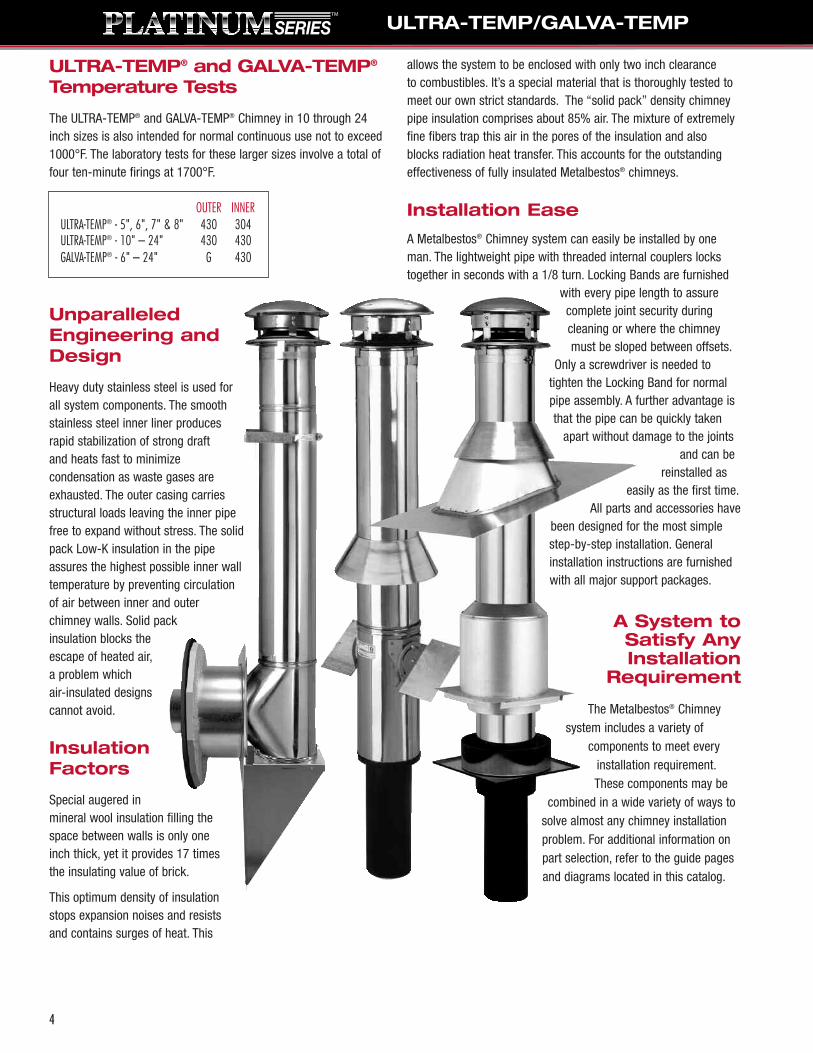
ULTRA-TEMP® and GALVA-TEMP®
Temperature Tests
The ULTRA-TEMP® and GALVA-TEMP® Chimney in 10 through 24inch sizes is also intended for normal continuous use not to exceed1000°F. The laboratory tests for these larger sizes involve a total offour ten-minute firings at 1700°F.
UnparalleledEngineering andDesign
Heavy duty stainless steel is used forall system components. The smoothstainless steel inner liner producesrapid stabilization of strong draftand heats fast to minimizecondensation as waste gases areexhausted. The outer casing carriesstructural loads leaving the inner pipefree to expand without stress. The solidpack Low-K insulation in the pipeassures the highest possible inner walltemperature by preventing circulationof air between inner and outerchimney walls. Solid packinsulation blocks theescape of heated air,a problem which air-insulated designscannot avoid.
InsulationFactors
Special augered inmineral wool insulation filling thespace between walls is only oneinch thick, yet it provides 17 timesthe insulating value of brick.
This optimum density of insulationstops expansion noises and resistsand contains surges of heat. This
allows the system to be enclosed with only two inch clearance to combustibles. It’s a special material that is thoroughly tested tomeet our own strict standards. The “solid pack” density chimneypipe insulation comprises about 85% air. The mixture of extremelyfine fibers trap this air in the pores of the insulation and alsoblocks radiation heat transfer. This accounts for the outstandingeffectiveness of fully insulated Metalbestos® chimneys.
Installation Ease
A Metalbestos® Chimney system can easily be installed by oneman. The lightweight pipe with threaded internal couplers lockstogether in seconds with a 1/8 turn. Locking Bands are furnished
with every pipe length to assurecomplete joint security duringcleaning or where the chimneymust be sloped between offsets.
Only a screwdriver is needed totighten the Locking Band for normalpipe assembly. A further advantage isthat the pipe can be quickly taken
apart without damage to the jointsand can be
reinstalled aseasily as the first time.
All parts and accessories havebeen designed for the most simplestep-by-step installation. Generalinstallation instructions are furnishedwith all major support packages.
A System toSatisfy AnyInstallation
Requirement
The Metalbestos® Chimneysystem includes a variety of
components to meet everyinstallation requirement.These components may be
combined in a wide variety of ways tosolve almost any chimney installationproblem. For additional information onpart selection, refer to the guide pagesand diagrams located in this catalog.
OUTER INNERULTRA-TEMP® - 5", 6", 7" & 8" 430 304ULTRA-TEMP® - 10" – 24" 430 430GALVA-TEMP® - 6" – 24" G 430
ULTRA-TEMP/GALVA-TEMP
4

Contents:Round Top CTAttic Insulation Shield AISStorm Collar SCFinish Support Pkg. FSPAdjustable Flashing AF-6Smoke Pipe Adapter DSAC
Contents:Round Top CTStorm Collar SCFinishing Collar FCRoof Support Pkg. RSPAdj. Pitched Ceiling Plate PCPAJSmoke Pipe Adapter DSAC
Contents:Round Top CT12" Insulated Pipe Length T-12Wall Band WBInsulated Tee/Plug ITFinishing Collar FCWall Support Kit WSKChimney Pipe Adapter CPAInsulated Wall Thimble IWT
Product No. Part No. Dia. Description206622 6T-TWK 6" Thru-the-Wall Support Kit208622 8T-TWK 8" Thru-the-Wall Support Kit
USE DSP STOVE PIPE FOR OPTIMUM SYSTEM PERFORMANCE
5
ULTRA-TEMP HT CHIMNEY KITSFour basic Chimney Kits designed around one of the standard support systems. Select the kit that is right for your installation
along with the required insulated pipe sections and you'll have what you need to complete most installations.
Roof Termination Kit (RTK)Includes the basic components for a standard installation. Contents: CT, AF-6 & SC
Product No. Part No. Dia. Description206600 6T-RTK 6" Roof Termination Kit (2/12 - 6/12)208600 8T-RTK 8" Roof Termination Kit (2/12 - 6/12)
Flat Ceiling Support Kit (FCK)Provides the support package and termination parts for a chimney that is supported by a
flat ceiling and passes through an attic area and penetrates the roof. Just add Pipe Lengthsand, the Flat Ceiling Support Kit (FCK) has all necessary parts for complete installation.However, depending upon your roof design and the position of your chimney on the roof, it may be necessary to install a Roof Brace Kit to provide required support for your chimneyabove the roof.
An Attic Insulation Shield is a required part of the installation even if you have noinsulation in the area where your chimney passes through the attic. The only exception tothis AIS installation is if you install a full enclosure around the chimney in the attic area atthe minimum two inch clearance.Product No. Part No. Dia. Description206620 6T-FCK 6" Flat Ceiling Support Kit208620 8T-FCK 8" Flat Ceiling Support Kit
Pitched Ceiling Support Kit (PCK)For installation of a chimney in a cathedral or pitched ceiling such as standard
A-Frame construction.The Pitched Ceiling Support Kit provides all necessary parts for a complete installation
with the exception of the required Insulated Pipe Lengths and Adjustable Flashing (AF).Selection of the Adjustable Flashing is determined by the pitch of your roof as explained on page 16.
In calculating the number of insulated Pipe Lengths your chimney run requires, note thatthe Roof Support Package (RSP) comes with one 18" pipe length as part of the support.
Product No. Part No. Dia. Description206621 6T-PCK 6" Pitched Ceiling Support Kit208621 8T-PCK 8" Pitched Ceiling Support Kit
Thru-the-Wall Support Kit (TWK)For a wall-supported chimney system with a horizontal connector passing through an
exterior wall, connecting to a Tee and running vertically up the exterior wall to terminationabove the roof line. The Thru-the-Wall Support Kit provides all necessary parts for acomplete installation with the exception of required Insulated Pipe Lengths to reach yourdesired chimney height.
One Wall Band (WB) is included in the kit. Additional Wall Bands could be required if your vertical chimney run is more than 16 feet high. In the event that your vertical chimneyrun penetrates the roof eave, your installation could also require an Adjustable Flashing(AF) and Storm Collar (SC).
ULTRA-TEMP/GALVA-TEMP
Smoke Pipe Adapter

READ AND FOLLOW THE INSTALLATIONINSTRUCTIONS WHEN INSTALLING ANYCHIMNEY SYSTEM.
4
CHIMNEY PARTS GUIDEThe following section offers pictorial references, specifications and a brief description of major components to aid in the design of an Ultra-Temp - Type HT, Galva-Temp - Type HT, Ultra-Temp, and Galva-Temp Chimney System.
Insulated Pipe
ULTRA-TEMP - TYPE HTSize Product No. Part No. A B C
206006U 6UT-6 6" 6" 8"206009U 6UT-9 9" 6" 8"206012U 6UT-12 12" 6" 8"206018U 6UT-18 18" 6" 8"206024U 6UT-24 24" 6" 8"206036U 6UT-36 36" 6" 8"206148U 6UT-48 48" 6" 8"
ULTRA-TEMP - TYPE HTSize Product No. Part No. A B C
205006U 5UT-6 6" 5" 7"205009U 5UT-9 9" 5" 7"205018U 5UT-18 18" 5" 7"205036U 5UT-36 36" 5" 7"
ULTRA-TEMP - TYPE HTSize Product No. Part No. A B C
207006U 7UT-6 6" 7" 9"207009U 7UT-9 9" 7" 9"207012U 7UT-12 12" 7" 9"207018U 7UT-18 18" 7" 9"207024U 7UT-24 24" 7" 9"207036U 7UT-36 36" 7" 9"207148U 7UT-48 48" 7" 9"
ULTRA-TEMP - TYPE HTSize Product No. Part No. A B C
208006U 8UT-6 6" 8" 10"208009U 8UT-9 9" 8" 10"208012U 8UT-12 12" 8" 10"208018U 8UT-18 18" 8" 10"208024U 8UT-24 24" 8" 10"208036U 8UT-36 36" 8" 10"208148U 8UT-48 48" 8" 10"
ULTRA-TEMPSize Product No. Part No. A B C
212006U 12U-6 6" 12" 14"212009U 12U-9 9" 12" 14"212012U 12U-12 12" 12" 14"212018U 12U-18 18" 12" 14"212024U 12U-24 24" 12" 14"212036U 12U-36 36" 12" 14"
ULTRA-TEMPSize Product No. Part No. A B C
214006U 14U-6 6" 14" 16"214009U 14U-9 9" 14" 16"214012U 14U-12 12" 14" 16"214018U 14U-18 18" 14" 16"214024U 14U-24 24" 14" 16"214036U 14U-36 36" 14" 16"
ULTRA-TEMPSize Product No. Part No. A B C
210006U 10U-6 6" 10" 12"210009U 10U-9 9" 10" 12"210012U 10U-12 12" 10" 12"210018U 10U-18 18" 10" 12"210024U 10U-24 24" 10" 12"210036U 10U-36 36" 10" 12"
800.992.8368 • Fax Orders Toll Free 877.393.4145
LOCKING BANDProduct No. Part No.205450 5T-LB206450 6T-LB207450 7T-LB208450 8T-LB210450 10S-LB212450 12S-LB214450 14S-LB
6
Note:All insulatedpipe lengths arefurnished with aLocking Band.
Size
12"
Size
10"
Size
7"
Size
6"
Size
5"
Size
14"
Size
8"
NEW lengths NOW available!
Large Diameter Platinum Series™ Galva-Temp® now available in 16" and 18" diameter. 20",22" and 24" diameter and stainless steel outer wall available by special order. For moreinformation see page 20.
ULTRA-TEMP/GALVA-TEMP
7
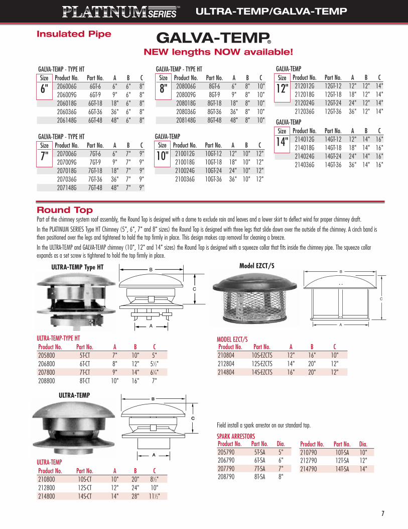
ULTRA-TEMP
Model EZCT/S
Round TopPart of the chimney system roof assembly, the Round Top is designed with a dome to exclude rain and leaves and a lower skirt to deflect wind for proper chimney draft.
In the PLATINUM SERIES Type HT Chimney (5", 6", 7" and 8" sizes) the Round Top is designed with three legs that slide down over the outside of the chimney. A cinch band isthen positioned over the legs and tightened to hold the top firmly in place. This design makes cap removal for cleaning a breeze.
In the ULTRA-TEMP and GALVA-TEMP chimney (10", 12" and 14" sizes) the Round Top is designed with a squeeze collar that fits inside the chimney pipe. The squeeze collarexpands as a set screw is tightened to hold the top firmly in place.
ULTRA-TEMP Type HT
ULTRA-TEMP-TYPE HTProduct No. Part No. A B C205800 5T-CT 7" 10" 5"206800 6T-CT 8" 12" 51⁄2"207800 7T-CT 9" 14" 61⁄4"208800 8T-CT 10" 16" 7"
ULTRA-TEMPProduct No. Part No. A B C210800 10S-CT 10" 20" 81⁄2"212800 12S-CT 12" 24" 10"214800 14S-CT 14" 28" 111⁄2"
MODEL EZCT/SProduct No. Part No. A B C210804 10S-EZCTS 12" 16" 10"212804 12S-EZCTS 14" 20" 12"214804 14S-EZCTS 16" 20" 12"
SPARK ARRESTORSProduct No. Part No. Dia.205790 5T-SA 5"206790 6T-SA 6"207790 7T-SA 7"208790 8T-SA 8"
Product No. Part No. Dia.210790 10T-SA 10"212790 12T-SA 12"214790 14T-SA 14"
Field install a spark arrestor on our standard top.
GALVA-TEMP - TYPE HT Size Product No. Part No. A B C
206006G 6GT-6 6" 6" 8"206009G 6GT-9 9" 6" 8"206018G 6GT-18 18" 6" 8"206036G 6GT-36 36" 6" 8"206148G 6GT-48 48" 6" 8"
GALVA-TEMP - TYPE HTSize Product No. Part No. A B C
207006G 7GT-6 6" 7" 9"207009G 7GT-9 9" 7" 9"207018G 7GT-18 18" 7" 9"207036G 7GT-36 36" 7" 9"207148G 7GT-48 48" 7" 9"
GALVA-TEMP - TYPE HT Size Product No. Part No. A B C
208006G 8GT-6 6" 8" 10"208009G 8GT-9 9" 8" 10"208018G 8GT-18 18" 8" 10"208036G 8GT-36 36" 8" 10"208148G 8GT-48 48" 8" 10"
Size
6"Size
8"
Size
7"
GALVA-TEMP Size Product No. Part No. A B C
212012G 12GT-12 12" 12" 14"212018G 12GT-18 18" 12" 14"212024G 12GT-24 24" 12" 14"212036G 12GT-36 36" 12" 14"
GALVA-TEMP Size Product No. Part No. A B C
214012G 14GT-12 12" 14" 16"214018G 14GT-18 18" 14" 16"214024G 14GT-24 24" 14" 16"214036G 14GT-36 36" 14" 16"
GALVA-TEMP Size Product No. Part No. A B C
210012G 10GT-12 12" 10" 12"210018G 10GT-18 18" 10" 12"210024G 10GT-24 24" 10" 12"210036G 10GT-36 36" 10" 12"
Size
12"
Size
10"
Size
14"
Insulated Pipe
NEW lengths NOW available!
ULTRA-TEMP/GALVA-TEMP

8
Chimney Offset Table
15°/30° Insulated Elbow Kits15° Insulated Elbows can be used for fixed offsets of 15° slope or in pairs for offsets adjustable from zero degrees to 30 degrees slope. The 30° Insulated Elbow in 5", 6", 7"and 8 inch sizes can be used for fixed offsets of 30 degrees slope. Greater angles are prohibited by UL® Standard 103 and by the terms of the product listing.
ULTRA-TEMP-TYPE HT 15° EL KitsProduct No. Part No. A B205206 5T-EL 15 KIT 115⁄8" 31⁄16"206206 6T-EL 15 KIT 115⁄8" 31⁄16"207206 7T-EL 15 KIT 121⁄2" 33⁄16"208206 8T-EL 15 KIT 125⁄8" 35⁄16"
ULTRA-TEMP-TYPE HT 30° EL KitsProduct No. Part No. A B205211 5T-EL 30 KIT 121⁄2" 61⁄4"206211 6T-EL 30 KIT 121⁄2" 61⁄4207211 7T-EL 30 KIT 133⁄4" 7"208211 8T-EL 30 KIT 143⁄4" 73⁄8"
ULTRA-TEMP 15° EL KitsProduct No. Part No. A B210206 10S-EL 15 KIT 135⁄8" 3 9⁄16"212206 12S-EL 15 KIT 145⁄8" 313⁄16"214206 14S-EL 15 KIT 155⁄8" 41⁄8 "
GALVA-TEMP Type HT 15° EL Product No. Part No. A B206206G 6GT--EL 15 KIT 135⁄8" 31⁄16"207206G 7GT-EL 15 KIT 145⁄8" 33⁄16"208206G 8GT-EL 15 KIT 155⁄8" 35⁄16"
GALVA-TEMP Type HT 30° EL KitsProduct No. Part No. A B206211G 6GT--EL 30 KIT 121⁄2" 61⁄4"207211G 7GT-EL 30 KIT 133⁄4" 7" 208211G 8GT-EL 30 KIT 143⁄4" 73⁄8"
Now includes 2 Elbows, 2 Locking Bands, 1 Interior Resupport and Couplers all in One Box!
Two 15° Elbows combineto be adjustable 0-30°
ULTRA-TEMP 30° EL KitsProduct No. Part No. A B210211 10U-EL 30 KIT 135⁄8" 7" 212211 12U-EL 30 KIT 145⁄8" 71⁄2"214211 14U-EL 30 KIT 155⁄8" 8"
GALVA-TEMP 30° EL KitsProduct No. Part No. A B210211G 10G-EL 30 KIT 135⁄8" 7"212211G 12G-EL 30 KIT 145⁄8" 71⁄2"214211G 14G-EL 30 KIT 155⁄8" 8"
ULTRA-TEMP/GALVA-TEMP
REQUIRED: Locking Bands (2 packaged with each elbow kit) are to be used at each joint. Each offset must be resupported. Elbows rotate 360º to provide the exact orientationrequired. Insulated Elbows can be used at the same two-inch air space clearance as chimney sections.
2 Elbows 2 Elbows 2 Elbows 2 Elbows 2 Elbows 2 Elbows 2 Elbows 2 ElbowsPart No. w/o Pipe + 6" Section + 9" Section + 12" Section + 18" Section + 24" Section + 36" Section + 48" Section
O H O H O H O H O H O H O H O H
5GT/UT - EL 15° 0.93" 7.03" 2.16" 11.62" 2.94" 14.52" N/A N/A 5.72" 23.21" N/A N/A 9.92" 40.60" N/A N/A
6GT/UT - EL 15° 1.04" 7.88" 2.27" 12.47" 3.05" 15.37" 3.82" 18.26" 5.38" 24.06" 6.92" 29.85" 10.03" 41.25" 13.03" 53.04"
7GT/UT - EL 15° 1.00" 7.62" 2.23" 12.21" 3.01" 15.11" 3.78" 18.00" 5.34" 23.80" 6.89" 29.59" 10.00" 41.19" 13.10" 52.78"
8GT/UT - EL 15° 0.97" 7.36" 2.20" 11.95" 2.98" 14.85" 3.75" 17.74" 5.31" 23.54" 6.85" 29.33" 9.96" 40.93" 13.07" 52.52"
*5GT/UT - EL 30° 3.64" 13.59" 6.02" 17.70" 7.52" 20.30" 9.02" 22.90" 12.02" 28.10" 15.02" 33.29" 21.02" 43.69" 27.02" 54.08"
*6GT/UT - EL 30° 4.08" 15.23" 6.45" 19.34" 7.96" 21.94" 9.45" 24.54" 12.45" 29.74" 15.45" 34.93" 21.45" 45.33" 27.45" 55.72"
*7GT/UT - EL 30° 3.95" 14.73" 6.33" 18.84" 7.83" 21.44" 9.33" 24.04" 12.33" 29.24" 15.33" 34.43" 21.33" 44.83" 27.33" 55.22"
*8GT/UT - EL 30° 3.81" 14.23" 6.19" 18.34" 7.69" 20.94" 9.19" 23.54" 12.19" 28.74" 15.19" 33.93" 21.19" 44.33" 27.19" 54.72"
5GT/UT - EL 30° 3.67" 13.75" 6.05" 17.86" 7.55" 20.46" N/A N/A 12.05" 28.26" N/A N/A 21.05" 43.84" N/A N/A
6GT/UT - EL 30° 3.82" 14.26" 6.20" 18.37" 7.70" 20.97" 9.19" 23.57" 12.20" 28.76" 15.20" 33.96" 21.20" 44.35" 27.20" 54.75"
7GT/UT - EL 30° 3.96" 14.76" 6.34" 18.87" 7.84" 21.47" 9.33" 24.07" 12.34" 29.26" 15.34" 34.46" 21.34" 44.85" 27.34" 55.25"
8GT/UT - EL 30° 4.09" 15.26" 6.47" 19.37" 7.97" 21.97" 9.46" 24.57" 12.46" 29.76" 15.47" 34.96" 21.47" 45.35" 27.47" 55.75"
*10GT/UT - EL 15° 1.24" 9.43" 2.47" 14.02" 3.25" 16.92" 4.02" 19.81" 5.58" 25.61" 7.12" 31.40" 10.23" 43.00" N/A N/A
*12GT/UT - EL 15° 1.00" 7.72" 2.23" 12.31" 3.01" 15.21" 3.78" 18.10" 5.33" 23.90" 6.88" 29.69" 9.99" 41.28" N/A N/A
*14GT/UT - EL 15° 1.06" 8.25" 2.29" 12.84" 3.07" 15.74" 3.84" 18.63" 5.39" 24.43" 6.95" 30.22" 10.05" 41.82" N/A N/A
10GT/UT - EL 30° 3.92" 15.18" 6.30" 19.29" 7.80" 21.89" 9.30" 24.49" 12.30" 29.70" 15.30" 34.88" 21.30" 45.27" N/A N/A
12GT/UT - EL 30° 3.92" 14.63" 6.30" 18.74" 7.80" 21.34" 9.30" 23.93" 12.30" 29.14" 15.30" 34.33" 21.29" 44.72" N/A N/A
14GT/UT - EL 30° 4.19" 15.63" 6.57" 19.74" 8.07" 22.34" 9.56" 24.93" 12.57" 30.14" 15.57" 35.33" 21.56" 45.72" N/A N/A
16GTL - EL 30° 7.96" 29.72" N/A N/A N/A N/A 13.33" 39.03" 16.33" 44.22" 19.33" 49.42" 25.33" 59.81" N/A N/A
18GTL - EL 30° 7.69" 28.72" N/A N/A N/A N/A 13.06" 38.02" 16.06" 43.22" 19.06" 48.42" 25.06" 58.81" N/A N/A
20GTL - EL 30° 7.42" 27.72" N/A N/A N/A N/A 12.79" 37.02" 15.79" 42.22" 18.79" 47.42" 24.79" 57.81" N/A N/A
22GTL - EL 30° 7.16" 26.72" N/A N/A N/A N/A 12.53" 36.02" 15.53" 41.22" 18.53" 46.42" 24.53" 56.81" N/A N/A
24GTL - EL 30° 6.89" 25.72" N/A N/A N/A N/A 12.26" 35.02" 15.26" 40.22" 18.26" 45.42" 24.26" 55.81" N/A N/A
NOTE: O = Offset; H = HeightAll dimensions and indicated lengths assume a 1.25" overlap... 5" through 10"; 15 degree elbows are new 2 gore design. ”*” are for a pair of 15 deg elbows.
9
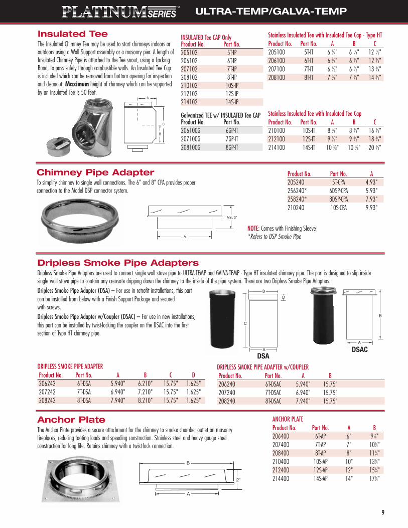
Dripless Smoke Pipe AdaptersDripless Smoke Pipe Adapters are used to connect single wall stove pipe to ULTRA-TEMP and GALVA-TEMP - Type HT insulated chimney pipe. The part is designed to slip insidesingle wall stove pipe to contain any creosote dripping down the chimney to the inside of the pipe system. There are two Dripless Smoke Pipe Adapters: Dripless Smoke Pipe Adapter (DSA) – For use in retrofit installations, this part can be installed from below with a Finish Support Package and secured with screws.Dripless Smoke Pipe Adapter w/Coupler (DSAC) – For use in new installations, this part can be installed by twist-locking the coupler on the DSAC into the first section of Type HT chimney pipe.
Anchor PlateThe Anchor Plate provides a secure attachment for the chimney to smoke chamber outlet on masonry fireplaces, reducing footing loads and speeding construction. Stainless steel and heavy gauge steel construction for long life. Retains chimney with a twist-lock connection.
DRIPLESS SMOKE PIPE ADAPTERProduct No. Part No. A B C D206242 6T-DSA 5.940" 6.210" 15.75" 1.625"207242 7T-DSA 6.940" 7.210" 15.75" 1.625"208242 8T-DSA 7.940" 8.210" 15.75" 1.625"
DRIPLESS SMOKE PIPE ADAPTER w/COUPLERProduct No. Part No. A B206240 6T-DSAC 5.940" 15.75"207240 7T-DSAC 6.940" 15.75"208240 8T-DSAC 7.940" 15.75"
ANCHOR PLATEProduct No. Part No. A B206400 6T-AP 6" 91⁄4"207400 7T-AP 7" 101⁄4"208400 8T-AP 8" 111⁄4"210400 10S-AP 10" 131⁄4"212400 12S-AP 12" 151⁄4"214400 14S-AP 14" 171⁄4"
DSADSAC
B
A
A
B
D
C
B
A
2"
Insulated TeeThe Insulated Chimney Tee may be used to start chimneys indoors oroutdoors using a Wall Support assembly or a masonry pier. A length ofInsulated Chimney Pipe is attached to the Tee snout, using a LockingBand, to pass safely through combustible walls. An Insulated Tee Capis included which can be removed from bottom opening for inspectionand cleanout. Maximum height of chimney which can be supportedby an Insulated Tee is 50 feet.
Chimney Pipe AdapterTo simplify chimney to single wall connections. The 6" and 8" CPA provides properconnection to the Model DSP connector system.
Stainless Insulated Tee with Insulated Tee Cap - Type HTProduct No. Part No. A B C205100 5T-IT 6 1⁄4" 6 1⁄4" 12 1⁄2"206100 6T-IT 6 3⁄8" 6 3⁄8" 12 3⁄4"207100 7T-IT 6 7⁄8" 6 7⁄8" 13 3⁄4"208100 8T-IT 7 3⁄8" 7 3⁄8" 14 3⁄4"
Product No. Part No. A205240 5T-CPA 4.93"256240* 6DSP-CPA 5.93"258240* 8DSP-CPA 7.93"210240 10S-CPA 9.93"
Stainless Insulated Tee with Insulated Tee Cap Product No. Part No. A B C210100 10S-IT 8 3⁄8" 8 3⁄8" 16 3⁄4"212100 12S-IT 9 3⁄8" 9 3⁄8" 18 3⁄4"214100 14S-IT 10 3⁄8" 10 3⁄8" 20 3⁄4"
NOTE: Comes with Finishing Sleeve *Refers to DSP Smoke Pipe
ULTRA-TEMP/GALVA-TEMP
Galvanized TEE w/ INSULATED Tee CAPProduct No. Part No.206100G 6GP-IT207100G 7GP-IT208100G 8GP-IT
INSULATED Tee CAP OnlyProduct No. Part No.205102 5T-IP206102 6T-IP207102 7T-IP208102 8T-IP210102 10S-IP212102 12S-IP214102 14S-IP
ULTRA-TEMP/GALVA-TEMP
10
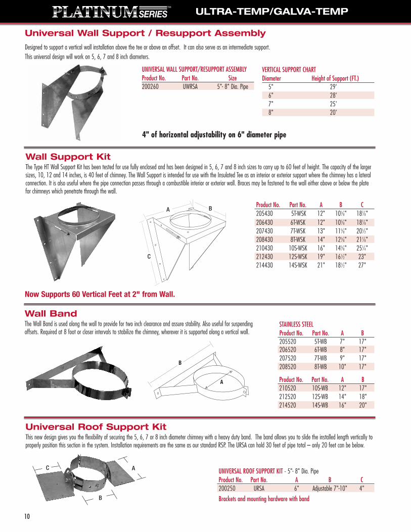
Wall BandThe Wall Band is used along the wall to provide for two inch clearance and assure stability. Also useful for suspendingoffsets. Required at 8 foot or closer intervals to stabilize the chimney, wherever it is supported along a vertical wall.
Product No. Part No. A B210520 10S-WB 12" 17"212520 12S-WB 14" 18"214520 14S-WB 16" 20"
Universal Roof Support KitThis new design gives you the flexibility of securing the 5, 6, 7 or 8 inch diameter chimney with a heavy duty band. The band allows you to slide the installed length vertically toproperly position this section in the system. Installation requirements are the same as our standard RSP. The URSA can hold 30 feet of pipe total – only 20 feet can be below.
UNIVERSAL ROOF SUPPORT KIT - 5"- 8" Dia. PipeProduct No. Part No. A B C200250 URSA 6" Adjustable 7"-10" 4"
Wall Support KitThe Type HT Wall Support Kit has been tested for use fully enclosed and has been designed in 5, 6, 7 and 8 inch sizes to carry up to 60 feet of height. The capacity of the largersizes, 10, 12 and 14 inches, is 40 feet of chimney. The Wall Support is intended for use with the Insulated Tee as an interior or exterior support where the chimney has a lateralconnection. It is also useful where the pipe connection passes through a combustible interior or exterior wall. Braces may be fastened to the wall either above or below the platefor chimneys which penetrate through the wall.
Product No. Part No. A B C205430 5T-WSK 12" 105⁄8" 187⁄8"206430 6T-WSK 12" 105⁄8" 187⁄8"207430 7T-WSK 13" 115⁄8" 201⁄2"208430 8T-WSK 14" 125⁄8" 217⁄8"210430 10S-WSK 16" 145⁄8" 251⁄4"212430 12S-WSK 19" 161⁄2" 23"214430 14S-WSK 21" 181⁄2" 27"
Universal Wall Support / Resupport Assembly
Designed to support a vertical wall installation above the tee or above an offset. It can also serve as an intermediate support.This universal design will work on 5, 6, 7 and 8 inch diameters.
UNIVERSAL WALL SUPPORT/RESUPPORT ASSEMBLYProduct No. Part No. Size200260 UWRSA 5"- 8" Dia. Pipe
VERTICAL SUPPORT CHARTDiameter Height of Support (FT.)
5" 29'6" 28'7" 25'8" 20'
4" of horizontal adjustability on 6" diameter pipe
C
Now Supports 60 Vertical Feet at 2" from Wall.
A
B
C
Brackets and mounting hardware with band
STAINLESS STEEL Product No. Part No. A B 205520 5T-WB 7" 17"206520 6T-WB 8" 17"207520 7T-WB 9" 17"208520 8T-WB 10" 17"
A B

ULTRA-TEMP/GALVA-TEMP
11
FSPR
CSP/FSP
Ceiling SupportsThe Finish Ceiling Support (FSP) in 5, 6, 7 and 8 inch sizes, is available with either a round or square trim plate.The Ceiling Support (CSP) in 10" size is unpainted on the back and comes with a square trim plate only.With proper framing, all ceiling supports assure at least 2 inch minimum clearance to combustibles at the support level and can carry up to 50 feet of vertical chimney height.
A B C DFraming Plate From
Product No. Part No. O.D. Dimensions Dimensions Ceiling210415 10S-CSP 101⁄4" 161⁄4" x 161⁄4" 181⁄2" 31⁄2"
ULTRA-TEMP - TYPE HTProduct No. Part No. A B Framing205420 5T-RSP 5" 7" 11" x t"206420 6T-RSP 6" 8" 12" x t"207420 7T-RSP 7" 9" 13" x t"208420 8T-RSP 8" 10" 14" x t"
GALVA-TEMP - TYPE HTProduct No. Part No. A B Framing206420 6T-RSP 6" 8" 12" x t"207420 7T-RSP 7" 9" 13" x t"208420 8T-RSP 8" 10" 14" x t"
ULTRA-TEMPProduct No. Part No. A B Framing210420 10S-RSP 10" 12" 16" x t"212420 12S-RSP 12" 14" 18" x t"214420 14S-RSP 14" 16" 20" x t"
ROOF SUPPORT KITBrackets and mounting hardware only
200420 RSK (works on all diameters)
A B C C DFraming Sq. Plate Rnd. Plate From
O.D. Dimensions Dimensions Product No. Part No. Dimensions Product No. Part No. Ceiling51⁄4" 111⁄4" x 111⁄4" – – – 17" 205411 5T-CSPR 31⁄2"61⁄4" 121⁄4" x 121⁄4" 141⁄4" 206410 6T-FSP 19" 206411 6T-FSPR 31⁄2"71⁄4" 131⁄4" x 131⁄4" 151⁄4" 207410 7T-FSP 21" 207411 7T-FSPR 31⁄2"81⁄4" 141⁄4" x 141⁄4" 161⁄4" 208410 8T-FSP 22" 208411 8T-FSPR 31⁄2"
Black Matte Finish
Roof Support PackageAn ideal support assembly for freestanding fireplaces and open cathedral ceiling installations. Fits all roof pitches andrequires only simple framing. Mounts easily on to top of roof through opening that allows two inch clearance.Maximum length of chimney which can be suspended below is 20 feet supported. Maximum total length is 30 feet.The Roof Support Package (RSP) contains one 18 inch length of pipe, roof brackets and necessary hardware.The roof brackets and hardware may be purchased without the pipe section by ordering a Roof Support Kit (RSK). The brackets may be assembled to any standard pipe length at any desired height.Locking bands must be used at each pipe joint when installing either the RSP or RSK.
NOTE: Framing dimension for the installation of the RSK isidentical to the RSP dimension.
Product No. Part No. Dia. Pipe206440 6T-RBK 6"207440 7T-RBK 7"208440 8T-RBK 8"
Roof Brace KitA Roof Brace Kit can be used whenever there is a need to stabilize the chimney above the roof level.The Roof Brace Kit should be used at a midpoint on the chimney. Braces adjust from 4 to 6 feet.
UNIVERSAL ROOF BRACE KITProduct No. Part No. Dia. Pipe
200240 URBK 5"-14"
ROOF BRACE KITS REQUIREMENTSup to 4' None5' to 10' 1over 10' 1 every 5'

12
Product No. Part No. A B C206424 6T-SB 61⁄4" 24" 141⁄4"207424 7T-SB 71⁄4" 24" 141⁄4"208424 8T-SB 81⁄4" 24" 141⁄4"Black Matte Finish
Support Box / Cathedral Ceiling SupportThe Support Box is intended for use when installing chimney in an A-frame, in a mobile home, or in a ceiling under a narrow section of roof. It provides a finished installation atthe ceiling level and will support up to 20 feet of 6, 7 or 8 inch diameter chimney. The part also provides shielding from insulation when installed in an unoccupied attic space.The Support Box assembly is comprised of a black box designed for installation inside 16 inch O.C. joists, a cylindrical shield, support bucket, ceiling trim, and four screws.
Interior ResupportInterior resupport assembly allows for two different methods of chimney resupport. The first method is used at the immediate section of chimney above the upper elbow of anoffset. With the appropriate Fire Stop/Joist Shield (JS) in place, clamp the support band around chimney and attach with six sheet metal screws. The second means of support is used primarily when the immediate sections of the upper offset do not pass through a joist area and resupport is necessary. The Support Band is clamped around the chimneyimmediately below a Locking Band. In both methods, the straps are nailed to suitable framing at two inch clearance. The 18 foot limit of supportable chimney length applies.
Dia. Product No. Part No.5" 205435 5T-IR6" 206435 6T-IR7" 207435 7T-IR8" 208435 8T-IR
10" 210435 10S-IR12" 212435 12S-IR14" 214435 14S-IR
Product No. Part No. A205490 5T-AIS 13"206490 6T-AIS 14"207490 7T-AIS 15"208490 8T-AIS 16"210490 10S-AIS 18"212490 12S-AIS 20"214490 14S-AIS 22"
ULTRA-TEMP/GALVA-TEMP
Universal Interior ResupportIncorporates the flexibility to work on 5, 6, 7 and 8 inch diameters and is an excellent method for resupporting chimney systems that have offsets or vertical runs that requireadditional support (up to 18 feet). Product No. Part No. Size
200230 UIRA 5"- 8" Dia. Pipe
Attic Insulation ShieldUsed wherever a Ceiling Support, Finish Support, or Fire Stop is installed below anopen attic. The Insulation Shield is required to guard against the hazard of blown-inor blanket insulation filling any framed opening or contacting the chimney andpossible contact of combustibles against the chimney.

13
ULTRA-TEMP/GALVA-TEMP
MOBILE HOME JOIST SHIELD (FLAT) Product No. Part No. Dia. Description A B206470 6T-MH 6" Mobile Home Joist Shield (flat) 141⁄4" 12"207470 7T-MH 7" Mobile Home Joist Shield (flat) 151⁄4" 13"208470 8T-MH 8" Mobile Home Joist Shield (flat) 161⁄4" 14"
CATHEDRAL ADAPTER FOR T-MH Product No. Part No. Dia. Description206475 6T-MHCA 6" Cathedral Adapter for T-MH (2/12-4/12)
Mobile Home ShieldingOften required part when installing Metalbestos chimneys in mobile home construction.
Trim Plate SpacerUsed to trim the ceiling, closing off the airspace around the pipe. Supported from above andextended down into room. Used in conjuction with Firestop/Joist Shield.
Firestop / Joist ShieldUsed in floor/ceiling penetrations other than those which include a ceiling support.Not required when passing through roof.
Product No. Part No. Dia. A B C D205465 5T-JS 5" 71⁄8" 9" 13" 11"206465 6T-JS 6" 81⁄8" 10" 14" 12"207465 7T-JS 7" 91⁄8" 11" 15" 13"208465 8T-JS 8" 101⁄8" 12" 16" 14"210465 10S-JS 10" 121⁄8" 14" 18" 16"212465 12S-JS 12" 141⁄8" 16" 20" 18"214465 14S-JS 14" 161⁄8" 18" 22" 20"
Product No. Part No. Dia. A B C206465 5T-TPS 5" – 11" 71⁄8"206465 6T-TPS 6" 19" 12" 81⁄8"207465 7T-TPS 7" 21" 13" 91⁄8"208465 8T-TPS 8" 22" 14" 101⁄8"
CUSTOMER SERVICE 800.992.8368
FAX ORDERS TOLL FREE 877.393.4145
A
B
A
B
MHCA MH installed in MHCA
C

Adjustable Pitched Ceiling PlateThe Pitched Ceiling Plate provides a finished appearance where the chimney passes through a sloped ceiling. Only two parts required to fit the full range of pitches.
Product No. Part No. A B206480 6T-FC 61⁄4" 8"207480 7T-FC 71⁄4" 9"208480 8T-FC 81⁄4" 10"
Black Matte Finish
Finishing CollarThe Finishing Collar fits over lower end of suspended insulated chimneypipe to provide finished appearance. Used to attach T-DSA Smoke PipeAdapter to lower end of chimney or to insulated Tee.
AB
Black Matte Finish
Storm CollarThe Storm Collar is designed to fit on the round chimney pipe just above the roof flashing.The upper edge of the Storm Collar should be waterproofed with silicone sealer to preventany water from leaking between the Storm Collar and chimney pipe. Part is tightened withadjusting screws or tabs after proper positioning.
Product No. Part No. A206810 5/6T-SC 8"208810 7/8T-SC 10"
Product No. Part No. A210810 10S-SC 12"212810 12S-SC 14"214810 14S-SC 16"
Insulated Wall ThimbleOur Insulated Wall Thimble installs quickly and eliminates the need for using individual firestops. The round shielding acts as a radiation shield and provides therequired two inch air space clearance to combustibles. The two sections telescope to accommodate 6 to 11 inch wall thickness.
Product No. Part No. A B Opening Required205463 5T-IWT 17" 16" 111⁄8" by 111⁄8"206463 6T-IWT 19" 16" 121⁄8" by 121⁄8"207463 7T-IWT 21" 16" 131⁄8" by 131⁄8"208463 8T-IWT 22" 16" 141⁄8" by 141⁄8"210463 10S-IWT 24" 181⁄4" 161⁄8" by 161⁄8"212463 12S-WT 20" 20" 181⁄8" by 181⁄8"214463� 14S-WT 24" 24" 201⁄8" by 201⁄8"
0/12 - 6/12 PITCH Size Product No. Part No. A B5" 205512 5T-PCPAJ 151⁄2" 18 - 29"6" 206512 6T-PCPAJ 161⁄2" 19 - 30"7" 207512 7T-PCPAJ 171⁄2" 20 - 31"8" 208512 8T-PCPAJ 181⁄2" 21 - 33"10" 210512 10S-PCPAJ 201⁄2" 23 - 37"12" 212512 12S-PCPAJ 221⁄2" 25 - 41"14" 214512 14S-PCPAJ 241⁄2" 27 - 45"
AB
ULTRA-TEMP/GALVA-TEMP
14
6/12 - 12/12 PITCH Size Product No. Part No. A B5"6"7"8"10"12"14"
COMING SOONContact
Customer Service for more info
800.992.8368

15
ULTRA-TEMP/GALVA-TEMP
0 To 2/12 PitchProduct No. Part No. A B C D206815 6T-TF 81⁄8" 12" 243⁄4" 21"207815 7T-TF 91⁄8" 153⁄4" 273⁄4" 24"208815 8T-TF 101⁄8" 153⁄4" 273⁄4" 24"210815 10S-TF 121⁄8" 173⁄4" 293⁄4" 293⁄4"212815 12S-TF 141⁄8" 20" 32" 32"214815 14S-TF 161⁄8" 221⁄4" 341⁄4" 341⁄4"
NOTE: All TF flashings come with a roof shield set.
Adjustable Flashing
Flat and Low Pitch Flashing (0 To 2/12 Pitch)
Flashings for Various Roof PitchesFlashings are used to seal the opening where the chimney penetrates the roof to divert rain and snow down from theroof and away from the chimney system.A series of adjustable flashings are available depending on your roof pitch. A flat and low pitch flashing is used to sealflat and low pitch roof (up to 2/12 pitch) openings.To determine your roof pitch, measure the number of inches from the end of a level ruler down to the roof. This is therise for 12 inches of run. A rise of 5 inches is a 5/12 pitch. . .4 inches, a 4/12 pitch, etc.
2/12 To 6/12 PitchProduct No. Part No. A B C D206825 6TAF-6 81⁄8" 161⁄2" 281⁄2" 24"207825 7TAF-6 91⁄8" 161⁄2" 281⁄2" 24"208825 8TAF-6 101⁄8" 197⁄8" 317⁄8" 27"210825 10SAF-6 121⁄8" 197⁄8" 317⁄8" 27"212825 12SAF-6 141⁄8" 197⁄8" 363⁄8" 36"214825 14SAF-6 161⁄8" 197⁄8" 363⁄8" 36"
6/12 To 12/12 PitchProduct No. Part No. A B C D206830 6TAF-12 81⁄8" 197⁄8" 317⁄8" 27"207830 7TAF-12 91⁄8" 197⁄8" 317⁄8" 27"208830 8TAF-12 101⁄8" 197⁄8" 317⁄8" 27"210830 10SAF-12 121⁄8" 251⁄2" 371⁄2" 36"212830 12SAF-12 141⁄8" 281⁄2" 401⁄2" 36"214830 14SAF-12 161⁄8" 311⁄2" 431⁄2" 36"
12/12 To 24/12 PitchProduct No. Part No. A B C D206835 6TAF-24 81⁄8" 283⁄4" 403⁄4" 24"207835 7TAF-24 91⁄8" 311⁄4" 431⁄4" 24"208835 8TAF-24 101⁄8" 333⁄8" 453⁄8" 24"
24/12 To 36/12 PitchProduct No. Part No. A B C D206840 6TAF-36 81⁄8" 411⁄4" 531⁄4" 24"207840 7TAF-36 91⁄8" 441⁄8" 561⁄4" 24"208840 8TAF-36 101⁄8" 473⁄4" 593⁄4" 24"
Safety Vents on all Flashings
D
NOTE: For 5 inch chimney use 6 inch Metalbestos® Flashing with 5/6 inch storm collar.All Flashings have .025 Aluminium Bases.
D
Dead Soft Flashing 2/12 To 6/12 PitchProduct No. Part No. A B C D206845 6T-AF6D 81⁄8" 161⁄2" 30" 33”207845 7T-AF6D 91⁄8" 161⁄2" 30" 33”208845 8T-AF6D 101⁄8" 197⁄8" 30" 33”
Universal Rubber Boot Flashing Kit Up To 12/12 PitchProduct No. Part No.200275 URBAK
Universal Metal Roof Flashing KitProduct No. Part No.200280 URFK
NOTE: Used in conjunction with a standardMetalbestos® Flashing to seal the openingwhen penetrating a corrugated metal roof. Flashing sold separately.

CHIMNEY SELECTION CHARTS
16
Pipe Length Selector ChartTotal in Chimney Size 6 9 12 18 24 36 48
Feet Inches Inches Installed Height 4 3/4 7 3/4 10 3/4 16 3/4 22 3/4 34 3/4 46 3/4
4 3/4 4 3/4 17 3/4 7 3/4 110 3/4 10 3/4 1
1 1/2 12 1/2 1 11 4 3/4 16 3/4 11 6 1/2 18 1/2 1 11 10 3/4 22 3/4 11 11 1/4 23 1/4 1 1 12 10 3/4 34 3/4 12 11 1/4 35 1/4 1 1 13 3 1/2 39 1/2 1 13 6 1/2 42 1/2 1 13 9 1/2 45 1/2 1 13 10 3/4 46 3/4 14 2 1/4 50 1/4 1 1 14 3 1/2 51 1/2 1 14 3 1/2 51 1/2 1 14 6 1/2 54 1/2 1 14 9 1/2 57 1/2 1 15 3 1/2 63 1/2 1 15 9 1/2 69 1/2 1 15 9 1/2 69 1/2 26 9 1/2 81 1/2 1 17 2 1/4 86 1/4 1 27 8 1/4 92 1/4 1 27 8 1/4 92 1/4 1 27 9 1/2 93 1/2 28 8 1/4 104 1/4 1 29 2 1/4 110 1/4 1 29 8 1/4 116 1/4 1 210 8 1/4 128 1/4 1 29 7 115 1 310 1 121 1 310 7 127 1 311 8 1/4 140 1/4 312 7 151 1 313 1 157 1 313 7 163 1 314 7 175 1 311 7 139 412 11 3/4 155 3/4 1 413 5 3/4 161 3/4 1 415 7 187 416 11 3/4 203 3/4 1 417 5 3/4 209 3/4 1 418 5 3/4 221 3/4 1 414 5 3/4 173 3/4 516 4 1/2 196 1/2 1 519 5 3/4 233 3/4 521 4 1/2 256 1/2 1 522 4 1/2 268 1/2 1 517 4 1/2 208 1/2 619 3 1/4 231 1/4 1 623 4 1/2 280 1/2 625 3 1/4 303 1/4 1 626 3 1/4 315 1/4 1 6
ULTRA-TEMP/GALVA-TEMP
17
ULTRA-TEMP/GALVA-TEMP
COMMON CHIMNEY INSTALLATIONSShort or tall, large or small, there is a Metalbestos® Chimney system to suit every need or appliance. The following diagrams are intended as a guide to proper part selection forseveral common chimney installations. Keep in mind that these diagrams do not show the exact details for installation of the various chimney parts. They supplement theinstructions, by illustrating a wider variety of complete chimney systems. While the primary emphasis in the diagrams is on solid-fuel appliances, the type of appliance originallyselected must never affect the installation of the chimney.
Whether the chimney is initially connected to a gas, oil, or wood-burning appliance, the parts used and clearances to combustibles are always the same. Remember that at somefuture time, the same chimney may serve a wood furnace, even if it started out with gas or oil.
Many more possibilities for chimney systems exist than those shown here. Whether or not you find your exact planned chimney arrangement here, remember these basicrules–which are also emphasized in the installation instructions:
1. Use proper support and bracing–for the entire system.
2. Maintain the minimum two inch AIR SPACE clearance to combustibles and to any insulation.
3. For joint security–use Locking Bands or screws for the chimney and its connector.
4. Enclose or protect the chimney to avoid contact, damage or hazards to furnishings.
5. Use only appliances which have been tested, “Listed” (or approved and inspected), and follow their instructions in every detail for your own protection.
NOTE: The drawings shown of these installations are solely for assistance in product selection. Reference should be made to the Metalbestos® Chimney system installationinstructions for full and exact details of a correct installation.
20 30 36 48 60 72 84
18
24
30
36
42
48
60
6 7 8 10 12 14 16 18 20 22 24
20 30 40 50 60 80 100
125
150
200
250
300
400 100
50
302015108
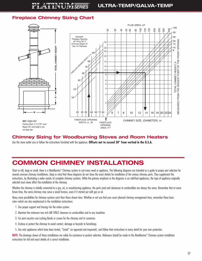
CHIMNEY SIZING CHART FOR FIREPLACESFLUE AREA, in2
FIREPLACE OPENING HEIGHT, i
n.,H
FIREPLACE OPENINGWIDTH, in., W FIREPLACE
OPENINGAREA. ft 2
CHIMNEY SIZE, (DIAMETER), in.
TOTA
L CH
IMNE
Y HE
IGHT
, ft.
MEA
SURE
D FR
OM
THE
HIG
HEST
PO
INT
OF
THE
FRO
NT O
PENI
NG40
3025
20
15
12
10
8
6
5
4
3
2
Example:Fireplace Opening
42” W by 30” HChimney Height 12ʼUse 14” Diameter
Fireplace Chimney Sizing Chart
Chimney Sizing for Woodburning Stoves and Room HeatersUse the stove outlet size or follow the instructions furnished with the appliance. Offsets not to exceed 30° from vertical in the U.S.A.
NOTE: CANADA ONLYChimney offsets (5' & 2-90° turns) Require 50% extra height or onesize larger pipe.

ULTRA-TEMP/GALVA-TEMP
3. Wood Heater with its chimney through an upstairs enclosure
4. Pitched Roof with Attic 5. A-Frame with chimney on a steep pitch roof
18
Round Top (T-CT)
Storm Collar (T-SC)
Flashing (T-TF)
MetalbestosChimney Pipe
Locking Bandsat All Joints
Finish Support(T-FSP) Package
Single WallPipe Elbow orCleanout Tee
Combined Ventingof Oil or GasAppliances
FurnaceWaterHeater
Correct ClearanceforType of Appliances
Construct a Full Enclosure inOccupied orHabitable Areas
3 FootMinimum
Ideas For Your Chimney Installation
2. Combination of Furnace and Water Heater on one chimney
1. Solid Fuel Appliance with ashort vertical chimney
Attic Insulation
Finish Support Pkg. (T-FSP)
Smoke PipeAdapter (DSAC)
DSP StovePipe
Solid FuelAppliance
Flashing(T-AF6) or(T-AF-12)
Round Top (T-CT)
Storm Collar (T-SC)
Attic InsulationShield (T-AIS)
Joist Shield(T-JS)
Flashing(T-AF6) or(T-AF12)
EitherFull Enclosure in Attic orAttic Insulation Shield
Round Top (T-CT)
Storm Collar (T-SC)
Full Enclosure inOccupied Areas, StorageAreas or Closets
Locking Bands atAll Joints
Finish Support Pkg. (T-FSP)
All ConnectionsSecured with Screws
SolidFuelAppliance
DSP SmokePipe
Smoke Pipe Adapter (DSAC)
Adjustable Pitched Ceiling Plate (T-PCPAJ)Used to Trim Opening
Round Top (T-CT)
Roof Brace Kit(T-RBK)
SelkirkType HT ChimneyPipeStorm Collar(T-SC)Locking Band
High PitchFlashing(T-AF)
2 FootMinimum
Roof Support (T-RSP)*Under Flashing
Suspended Length,Long Enough to ProvideRequired Clearance, Securedwith Locking Band or ScrewsFinishing Collar (T-FC)
Smoke Pipe Adapter (DSAC)
All ConnectorsSecured with Screws
IMPORTANT: FollowAppliance Instructionsfor All Clearances!
* Support Box may also be used. Pleaseconsult installations instructions for moreinformation.
DSP Stove Pipe
Round Top (T-CT)
SelkirkType HT Chimney
Attic Level
24" Maximum
SupportBox (T-SB)*
CeilingThe Support Box may be installed flush with the ceilinglevel. The Support Bucket mustexposed a minimum of 3-1/2"below the ceiling level.
Single Wall Smoke Pipe,or Model DSP Stove Pipe ,(Double Wall).
* Support box also intended for use in mobile home and A-frame installations.
Storm Collar(T-SC)
Locking BandFlashing(T-TF, T-AF6 orT-AF12)
Shield
TrimSupport Bucket
Smoke Pipe Adapter(DSAC)

DSP Smoke Pipe
Chimney Extension(T-9) or Longer)
Finishing Collar (T-FC) Wall Thimble(IWT)
ChimneyClearance toWall
Use Locking BandsAt Every Joint
Wall Band (T-WB)Needed Every 8'or Less
Round Chimney Top(T-CT)
Storm Collar (T-SC)
Flashing (T-AF6) or(T-AF12)
8'
Chimney PipeAdapter (CPA)
Tee Plug
Wall Support Kit(T-WSK)on OutsideWall
*The end of the chimney sectionmust extend into the room a minimum of 4-1/2" beyond the face of the wall.
*
Total ChimneyHeight is 85'Maximum on Anchor Plate
Chimney Pipe(T-18) or (T-36)
Joist Shield(T-JS) Attic Enclosure or
Attic Insulation Shield
Anchor Plate (T-AP)
All Masonry or Steel Shell
HW
7. Wood Stove with chimney offset to avoid ridge6. Basement Heater with Tee-supported outside chimney
8. Masonry Fireplace using Metalbestos® Chimney
NOTE ON CHIMNEY/SMOKE PIPE CONNECTIONS
Most diagrams on Pages 17, 18 and 19 show Ultra-Temp orGalva-Temp Chimney systems connected to Metalbestos®
double wall stove pipe using the Model DSP Chimney PipeAdapter (see page 9). Ultra-Temp and Galva-Temp Chimneysmay be connected to single wall stove pipe using theDripless Smoke Pipe Adapters (see page 9).
ULTRA-TEMP/GALVA-TEMP
19
Follow ApplianceInstructions forClearance
Model DSP Smoke Pipe
Smoke Pipe Adapter (DSAC)
Remove Attic Insulation Shield andEnclose Chimney if Attic Space isOccupied or Used for Storage
Use Locking Bands (T-LB) orThree Screws at Every Joint
Elbow/Offset (T-EL15) or(T-EL30)
Adjustable Pitch Flashing(T-AF6) or (T-AF12)
Storm Collar (T-SC)
Round Chimney Top (T-CT)
Framing as Neededfor Resupport
Resupport (T-IR)
Maximum RecommendedOffset is 30 DegreesFrom Vertical
Maximum Inclined Length - 96"or longer if supported every 48"
Elbow/Offsets (T-EL15)or (T-EL30)
Attic Insulation Shield (T-AIS)
Finish Support Package (T-FSP)

Metalbestos® Platinum Series™ Large Diameter Chimney isthe perfect fit for large custom masonry fireplaces. Selkirkoffers the best selection of large diameter chimney pipe in theindustry – 16 to 24 inch (20", 22", 24" available special order).
With its stainless steel inner pipe, 1 inch premium insulationand durable galvanized (stainless steel special order) outer pipe,our Platinum Series™ chimney system is “the coolest underthe hottest conditions.”
Listed with Underwriters Laboratories, Inc. for gas, wood andliquid-fired appliances, the Metalbestos® Platinum Series™ Large Diameter Chimney is backedby a lifetime warranty, the best in the industry.
The Better Chimney for Big Fireplaces.
16" – 24" DIAMETERS
LENGTH 6" TO 60"
LENGTH
IDOD=ID+ 2"
SIZE DIM "A" DIM "B"16"18"20"22"24"
16"18"20"22"24" 26"
24"22"20"18"
Large Diameter Lengths, Galvanized
Dia. Product No. Part No. Lengths16" 216036G 16GT-36 36"
216024G 16GT-24 24"216018G 16GT-18 18"216012G 16GT-12 12"
Notes for Ultra-Temp & Galva-Temp:- 20, 22 and 24 inch Chimney products in galvanized and stainless
steel are available by Special Order - allow four weeks.- 16 and 18 inch stainless steel lengths, tees, and elbows are
available by Special Order - allow four weeks.
C
DIM "A"
DIM "B"
26"
18"20"22"24"
24"24"28"32"32"24"
22"20"18"16"
SIZE DIM "A" DIM "B" DIM "C"
12"10"9"9"
12"
Round Top with Spark Arrestor
Closure Ring
Dia. Product No. Part No. A B C16" 216804 16S-EZCT/S 24" 18" 141⁄4"18" 218804 18S-EZCT/S 24" 20" 141⁄4"20" 220804 20S-EZCT/S 28" 22" 151⁄4"22" 222804 22S-EZCT/S 32" 24" 171⁄4"24" 224804 24S-EZCT/S 32" 26" 171⁄4"
Dia. Product No. Part No. Lengths18" 218036G 18GT-36 36"
218024G 18GT-24 24"218018G 18GT-18 18"218012G 18GT-12 12"
Dia. Product No. Part No. Lengths20" 220036G 20GT-36 36"
220024G 20GT-24 24"220018G 20GT-18 18"220012G 20GT-12 12"
Dia. Product No. Part No. Lengths22" 222036G 22GT-36 36"
222024G 22GT-24 24"222018G 22GT-18 18"222012G 22GT-12 12"
Dia. Product No. Part No. Lengths24" 224036G 24GT-36 36"
224024G 24GT-24 24"224018G 24GT-18 18"224012G 24GT-12 12"
NOTE: OD = ID + 2"
Required to cover the insulation at the top of the chimney if any termination other than Selkirk Round Top is used.
LISTED
LARGE DIAMETER CHIMNEY
20
Dia. Product No. Part No.16" 216807 16S-CR18" 218807 18S-CR20" 220807 20S-CR22" 222807 22S-CR24" 224807 24S-CR

21
LARGE DIAMETER CHIMNEY
DIM "B"
DIM "C"
3/16
0.588
0.635
DIM "A"
18"20"22"24"26"24"
22"20"18"16"
24"22"20"18"16"
SIZE DIM "A" DIM "B" DIM "C"
15"15"15"15 "15"
Dia. Product No. Part No. A B C16" 216210G 16GT-EL30 16" 18" 16"18" 218210G 18GT-EL30 18" 20" 16"20" 220210G 20GT-EL30 20" 22" 16"22" 222210G 22GT-EL30 22" 24" 16"24" 224210G 24GT-EL30 24" 26" 16"
30° Elbow
NOTE: Installed length is 3⁄4" less than “C” dimension.
Anchor Plate
1.50"
24"
DIM "A" 3.00"
SIZE DIM "A"16"18"20"22"24" 26"
24"22"20"18"
Interior Resupport
Attic Insulation Shield
Firestop/Joist ShieldDIM "A"
8.00"
DIM "C"
DIM "B"
DIM "D"
25"27"29"31"33"
SIZE DIM "A" DIM "B" DIM "C" DIM "D"16"18"20"22"24"
18.13"20.13"22.13"24.13"26.13" 28"
26"24"22"20"
30"28"26"24"22"
3.61"
DIM "B"
DIM "A"
18"20"22"24"26"24"
22"20"18"16"
SIZE DIM "A" DIM "B"
38"36"34"32"30
Storm Collar
3.00 MIN
DIM "A"
22.50"24.50"26.50"28.50"30.50"24"
22"20"18"16"
SIZE DIM "A"ÿ MAKE FROM8P-VTF
10P-VTF12P-VTF14P-VTF16P-VTF
LDC-130-MFG
Flat and Low Pitch Flashing (0 To 2/12 Pitch)
LDC-111-MFG
18"20"22"24"26"24"
22"20"18"16"
24"22"20"18"16"
SIZE DIM "A" DIM "B" DIM "C"
30"28"26"24"22"
DIM "B"DIM "A"
DIM "C"
5.88"7.88"
Plastic Sealer 1/16" Thick, 3/4" Wide, 25' Long Product No. Part No.100000 MB-S
Stabilizer Plate
A
A
A AProvides lateral support for a vertical chimney only.Is NOT a firestop.
Dia. Product No. Part No. A16" 216435 16S-IR 18"18" 218435 18S-IR 20"20" 220435 20S-IR 22"22" 222435 22S-IR 24"24" 224435 24S-IR 26"
Dia. Product No. Part No. A B16" 216490 16S-AIS 22" 24"18" 218490 18S-AIS 24" 26"20" 220490 20S-AIS 26" 28"22" 222490 22S-AIS 28" 30"24" 224490 24S-AIS 30" 32"
Dia. Product No. Part No. A B C16" 216400G 16GT-AP 16" 18" 22"18" 218400G 18GT-AP 18" 20" 24"20" 220400G 20GT-AP 20" 22" 26"22" 222400G 22GT-AP 22" 24" 28"24" 224400G 24GT-AP 24" 26" 30"
Dia. Product No. Part No. A B C D16" 216465 16S-JS 18.13" 20" 25" 22"18" 218465 18S-JS 20.13" 22" 27" 24"20" 220465 20S-JS 22.13" 24" 29" 26"22" 222465 22S-JS 24.13" 26" 31" 28"24" 224465 24S-JS 26.13" 28" 33" 30"
Dia. Product No. Part No. A16" 216405 16S-SP 25"18" 218405 18S-SP 27"20" 220405 20S-SP 29"22" 222405 22S-SP 31"24" 224405 24S-SP 33"
Dia. Product No. Part No. A B16" 216810 16S-SC 18" 30"18" 218810 18S-SC 20" 32"20" 220810 20S-SC 22" 34"22" 222810 22S-SC 24" 36"24" 224810 24S-SC 26" 38"
Dia. Product No. Part No. A16" 216872 16S-VTF 221⁄2"18" 218872 18S-VTF 241⁄2"20" 220872 20S-VTF 261⁄2"22" 222872 22S-VTF 281⁄2"24" 224872 24S-VTF 301⁄2"

LARGE DIAMETER CHIMNEY
22
2 Elbows w/o Pipe 2 Elbows w/o PipePart No. OFFSET HEIGHT
10GT/UT - EL 15° 1.24" 9.43"12GT/UT - EL 15° 1.00" 7.72"14GT/UT - EL 15° 1.06" 8.25"10GT/UT - EL 30° 3.92" 15.18"12GT/UT - EL 30° 3.92" 14.63"14GT/UT - EL 30° 4.19" 15.63"
16GTL - EL 30° 7.96" 29.72"18GTL - EL 30° 7.69" 28.72"20GTL - EL 30° 7.42" 27.72"22GTL - EL 30° 7.16" 26.72"24GTL - EL 30° 6.89" 25.72"
OFFSET @ HEIGHT @ OFFSET @ HEIGHT @ Number of Chimney Sections Assembled15 Degree 15 Degree 30 Degree 30 Degree 36" 24" 18" 12" Length
2.78" 10.38" 5.37" 9.31" 1 10.75"4.33" 16.18" 8.37" 14.51" 1 16.75"5.56" 20.76" 10.75" 18.62" 2 21.50"5.88" 21.97" 11.37" 19.70" 1 22.75"7.12" 26.56" 13.75" 23.82" 1 1 27.50"8.35" 31.15" 16.13" 27.92" 3 32.25"8.67" 32.36" 16.75" 29.02" 1 1 33.50"9.00" 33.57" 17.38" 30.01" 1 34.75"10.22" 38.15" 19.75" 34.21" 1 1 39.50"11.13" 41.53" 21.50" 37.24" 4 43.00"11.77" 43.95" 22.75" 39.40" 2 45.50"13.00" 48.54" 25.13" 43.52" 3 50.25"13.33" 49.75" 25.75" 44.60" 1 1 51.50"13.92" 51.92" 26.88" 46.55" 5 53.75"14.56" 54.33" 28.13" 48.71" 1 2 56.25"15.78" 58.92" 30.50" 52.83" 1 1 2 61.00"16.11" 60.13" 31.13" 53.91" 1 1 1 62.25"17.12" 63.51" 32.88" 56.94" 1 4 65.75"18.00" 67.13" 34.75" 60.20" 2 69.50"19.22" 71.72" 37.13" 64.30" 1 1 1 74.25"20.12" 75.10" 38.88" 67.33" 1 2 2 77.75"20.44" 76.31" 39.50" 68.42" 2 2 79.00"21.67" 80.90" 41.88" 72.53" 1 3 1 83.75"22.32" 83.31" 43.13" 74.70" 2 1 86.25"22.91" 85.48" 44.25" 76.64" 1 2 3 88.50"23.55" 87.90" 45.50" 78.81" 4 91.00"23.88" 89.12" 46.13" 79.90" 2 1 92.25"24.78" 92.49" 47.88" 82.93" 2 3 95.75"25.12" 93.69" 48.50" 84.10" 2 1 1 97.00"26.10" 97.10" 50.25" 87.10" 2 2 2 100.50"27.00" 100.70" 52.13" 90.30" 3 104.25"
TABLE 1
TABLE 2
Example of Chart Use:Using a 16" chimney and 30° elbows, what parts do I use to create an approximate 38.5" total horizontal offset?
1. From Table 1 - Determine the “Offset” two 16" 30° elbows give with no pipe length. Ans. = 7.96"2. Subtract that number (7.96") from 38.5". Ans. = 30.54" (This is the additional offset required.)3. From Table 2 determine the closest value to 30.54" in the “Offset @ 30 Degree” column. Ans. = 30.50" 4. Reference the adjacent “Number of Chimney Section” columns to the right to determine the required
lengths. Ans. = 1 @ 24", 1 @ 18" and 2 @ 12". SUMMARY: In addition to the 2 - 30° elbows, the required lengths are: one - 24" one - 18" two - 12".
Altogehter they will create an offset of 7.96" + 30.50" = 38.46" NOTE: To determine the amount of height this assembly will require, follow a similar procedure using the
“Height” columns in each table. In this example the total installed height of the assembly will be: 29.72" (elbows) + 52.83" (inclined chimney portion) = 82.55"
PIPE LENGTH SELECTOR CHART FOR LARGE DIAMETER CHIMNEY (INSTALLED LENGTH)
Numerous other combinations may befound too, by adding multiples of individuallengths.

23
Better Insulating Value = Superior Stove Performance:Double wall construction with a 1/4 inch air space between innerand outer pipes provides superior insulating value than single wallpipe. Better insulating value keeps flue gas temperatureshigher. This helps your wood stove perform with anenhanced draft, which provides:
• Less chance of moisture or soot build up within the vent
• Reduced “smoking” of the stove at start-up• Increased efficiency
Superior Performance = Reduced Clearances (from 18" to only 6"):Double Wall Stove Pipe not only keepsthe flue temperatures higher, it keepsthe outer pipe temperatures cooler.This allows Double Wall Stove Pipe to be installed with only 6-inchclearance to combustible materials.Single wall stove pipe requires an 18- inch clearance, which typicallymeans your wood stove sits furtheraway from the wall and takes upvaluable space within the room.
Stainless Steel = Quality:The inner liner of Model DSP is made from corrosion resistant 400 series stainless steel. Together with the stainless steelinsulated chimney this combination forms an all-stainless steelsystem to help your wood stove perform safely and efficiently.
Double Wall Stove Pipe is listed to ULC S-641 and UL103 Standards—your guarantee of safety.
Quality = Longer Life: The premium materials used to construct Model DSPenable the manufacturer to offer a Lifetime Warranty.Single wall stove pipe is made from simple carbonsteel and typically needs replacement every two orthree years.
Advanced Design = Easy Installation:Model DSP is available in a variety of lengths andelbows for ease of installation. Telescopic andAdjustable Lengths are available to eliminate cutting-to-size and help easily access the system for cleaning or inspection.
Premium Paint Finish = Better Value: The black finish of Model DSP provides a very rich and distinguished appearance. Black enamel paint is used to provide a long lasting, brighter finish that
also resists scratches.
Model DSP is a connector pipe that links your wood stove to an insulated chimney. The connector is an important component of a woodburning system because its correct size, arrangement and installation improve the performance and safety of the heating system.
Listed & Tested to ULC Standard S-641 and UL-103 Standards. Model DSP has an attractive outer black paintedsurface made of durable aluminized steel to withstand temperatures up to 1200 degrees F of continuousoperation.
Remove the “WEAK LINK” in your wood heating system. Install MODEL DSP Double Wall Stove Pipe.
MODEL DSP — Double Wall Stove Pipe
Double Wall Design Advantages
DOUBLE WALL STOVE PIPE

DOUBLE WALL STOVE PIPE
24
• Includes Finishing Band.• Adjustable from 12" to 18".• Used to adjust pipe to desired Length.• Eliminates the need to cut pipe.• For installed length, subtract 1-3/8" per joint.
• Adjusts from 36" to 68".• Includes everything you need for most ceiling supported
installations with Ultra-Temp® and Galva-Temp® Chimney.• Kit Includes:
- Ultra-Temp® and Galva-Temp® Chimney Adapter (T-CPA)- DSP Telescopic Length (DSP-TL)- DSP Finishing Band
• Available in lengths of 6", 12", 24" and 36".• 3 metal screws supplied with each length.• For installed length, subtract 1-3/8" per joint.
ALL DSP COMPONENTS ARE INDIVIDUALLY PACKED TO PROTECT PAINTED SURFACES.
D
➤
➤C
➤
➤
E
➤
➤
D
➤
➤
A ➤
➤
B ➤
➤
A ➤
➤
B ➤
➤
B
➤
➤C
➤
➤
Parts & Accessories
Adjustable Lengths
Vertical Installation Kit
Fixed Lengths
Size Product No. Part No. A B C D E6" 266086 DSP6AL-1 529⁄32" 61⁄2" 6" 613⁄32" 121⁄2" - 18"8" 268086 DSP8AL-1 729⁄32" 81⁄2" 8" 813⁄32" 121⁄2" - 18"
Size Product No. Part No. A B C D266006 DSP8P6-1 729
⁄32" 81⁄2" 8" 6"
266012 DSP8P12-1 729⁄32" 81
⁄2" 8" 12"266024 DSP8P24-1 729
⁄32" 81⁄2" 8" 24"
266036 DSP8P36-1 729⁄32" 81
⁄2" 8" 36"
Size Product No. Part No. A B C D266006 DSP6P6-1 529
⁄32" 61⁄2" 6" 6"
266012 DSP6P12-1 529⁄32" 61
⁄2" 6" 12"266024 DSP6P24-1 529
⁄32" 61⁄2" 6" 24"
266036 DSP6P36-1 529⁄32" 61
⁄2" 6" 36"
Size
8"
Size
6"
Size Product No. Part No.6" 266610 DSP6VK8" 268610 DSP8VK

DOUBLE WALL STOVE PIPE
25
• Used to offset Double Wall Stove Pipe toward insulated chimney in a through the wall installation.• Non-positional connection system allows 360° rotation.
C ➤
D➤
➤
➤
➤
➤
E
➤
➤
A
➤
➤
B
• Used to offset Double Wall Stove Pipe toward insulated chimney.• Non-positional connection system allows 360° rotation.
• Includes Cap.• Used in conjunction with a vertical insulated chimney to provide easy access
for inspection and cleaning.
➤
➤
E
AB
➤
➤
D➤C
➤
➤
➤
➤
➤
➤
B➤C
➤
➤
➤
B
➤ A➤
➤
➤
➤
D
➤
➤
C
➤
➤
B➤
➤
E
Parts & Accessories
Model DSP vs Single Wall Stove Pipe Comparison Chart
For the complete DSP product listing, order our DSP catalog – SDSP002-E
Finishing Band(Universal)
Insulated WallThimble
Damper Kit Stove Adapter
Universal Chim. Adapter
Increaser MasonryAdapter
Reducer Oval to RoundAdapter
90 Degree Elbow
45 Degree Elbow
Tee
Size Product No. Part No. A B C D E6" 266230 DSP6E9K 529⁄32" 61⁄2" 6" 61⁄2" 9"8" 268230 DSP8E9K 729⁄32" 81⁄2" 8" 81⁄2" 9"
Size Product No. Part No. A B C D E6" 266215 DSP6E4-1 529⁄32" 61⁄2" 6" 61⁄2" 6"8" 268215 DSP8E4-1 729⁄32" 81⁄2" 8" 81⁄2" 8"
Size Product No. Part No. A B C D E6" 266100 DSP6TE-1 529⁄32" 61⁄2" 6" 133⁄4" 6"8" 268100 DSP8TE-1 729⁄32" 81⁄2" 8" 153⁄4" 7"
CLEARANCESPRODUCT TESTED & LABELED MATERIAL TO COMBUSTIBLE WARRANTY
MODEL DSP DOUBLE WALL STOVE PIPE TO ULC S641 HEAVY GAUGE STAINLESS STEEL/ 6 INCHES LIFETIME WARRANTYALUMINIZED STEEL
SINGLE WALL STOVE PIPE NOT TESTED OR LABELED LIGHT GAUGE CARBON STEEL 18 INCHES NO WARRANTY*
* If a wood burning appliance is used every day during the heating season, surveys have shown that a single wall stove pipe will need replacement everytwo or three years.

OFFSET HEIGHT LENGTHS REQUIRED BETWEEN ELBOWS6" Dia. 7" Dia. 8" Dia. 6" Dia. 7" Dia. 8" Dia. 6" 12" AL 24" 36" TL
6 63⁄4 6 137⁄8 141⁄2 141⁄891⁄2 93⁄4 91⁄4 17 173⁄4 171⁄4 1131⁄2 133⁄4 131⁄4 211⁄8 221⁄8 213⁄4 1163⁄4 163⁄4 155⁄8 245⁄8 251⁄2 253⁄4 1 1171⁄4 173⁄4 171⁄2 253⁄4 261⁄4 257⁄8 1223⁄4 22 211⁄2 291⁄4 301⁄4 307⁄8 1251⁄2 251⁄4 24 311⁄2 333⁄4 34 1 1291⁄8 311⁄4 303⁄4 383⁄4 373⁄4 383⁄4 1323⁄8 313⁄4 32 401⁄8 421⁄2 413⁄4 1 1 1593⁄4 51 541⁄2 601⁄4 601⁄4 60 1
DOUBLE WALL STOVE PIPE
26
Insulated Chimney Section
Insulated Tee Section
Wall Thimble
Wall Support
Stove Pipe Adaptor
Universal Chimney Adaptor(optional)
90 Degree Elbow
Telescopic Length
6"
6"
Wood Burning Stove
Wood Burning Stove
Insulated Chimney Section
Stove Pipe Adaptor
Universal Chimney Adaptor (optional)
90 Degree Elbow
6"
Tee SectionTelescopic Length
Ceiling Support
Fixed Length or Adjustable Length
90 Degree Elbow
Telescopic Length
Stainless Steel Chimney LinerMasonry Chimney
Masonry Adaptor
Metal Screws
Wood Burning Stove
6"
VERTICAL INSTALLATION THROUGH THE WALL INSTALLATION
INSTALLATION WITH A CLEAN-OUT TEE
INSTALLATION INTO A RELINED MASONRY
Additional Pipelengths may berequired forCathedral CeilingInstallations.
This chart has three columns for elbow angle required to achieve your desired offset. The first column (“Offset”) is the horizontal measurement, at the chimney center line of the offset needed to get around an obstacle. The second column (“Height”) is the height of the assembled offset elbow to the top of the return elbow. Column 3 shows the appropriate lengths required.
1. Determine the distance of the offset required.
2. On the chart, find the predetermined distance required for the 45° elbow under the corresponding chimney diameter.
3. After finding the offset, follow across the chart to find the specified height and appropriate chimney lengths required under their corresponding diameters.
45 DEGREE OFFSET CHART
➤ ➤
➤
➤
OFFSET
HEIGHT
Common Installations
MODEL DSP OFFSET CHART
Insulated ChimneySection
Ceiling SupportStove Pipe Adaptor
Universal Chimney Adaptor(optional)
Telescopic Length
WoodBurningStove
6"

MODEL VP PELLET PIPE™
27
• Available in 3" and 4" diameters.• Full line of fittings and full range of pipe lengths
increase installation flexibility.• Proven coupling joint connects in seconds
to assure joint integrity.• Gasketed joint design.• Painted pipe lengths available for interior use.• Inner wall 304 stainless steel, outer wall paintable
galvanized.
• Rolled-over male endeliminates sharp edges.
• 3" clearance tocombustibles.
• Removable tee cap forinspection and cleaning.
• Internal spacing bead assures uniforminsulating air space between pipe walls.
MODEL VP Pellet Pipe™ for Pellet and Corn AppliancesMetalbestos® gives you the safe, efficient, and cost-effective venting system that's engineered precisely for pellet and corn burning stoves. Model VP Pellet Pipe has beentested and listed by Underwriters' Laboratories, Inc., in accordance with UL®-641 Standard for Low Temperature Venting Systems, as well as the applicable requirements from UL®-103 Standard for Residential Type and Building Heating Appliance Chimneys.Model VP Pellet Pipe, when installed according to Metalbestos® installation instructions, complies with National Safety Standards,such as NFPA -211. The system is rated for flue temperatures up to 570°F.
MINIMUM CLEARANCE TO COMBUSTIBLESMetalbestos® Model VP Pellet Pipe™ may be installed with a minimum 3" air space clearance to combustible surfaces, such as framing lumber, drywall, plywood, or other buildingmaterials. Model VP Pellet Pipe™ may be exposed in occupied areas and painted pipe lengths help make your venting system an attractive accent to your interior decor.However, your venting system should be enclosed whenever it passes through closets, storage rooms, or accessible attics to ensure that the minimum 3 inch air space clearanceis maintained. This is particularly true in attics where cellulose-type or other blown-in Insulation materials could settle against the exposed vent pipe.It is also advisable to provide an enclosed chase for exterior vent systems to aid in reducing condensation and to protect the pipe from cold outdoor temperatures. Model VP Pellet Pipe™ features a proven joint design that allows for easy assembly. Special rope gaskets incorporated into the joint reduce leakage and help to minimize any accumulation of combustion powder residues. In addition, Model VP Pellet Pipe™ is listed for use with an optional, high temperature silicon sealant which enhances the integrity of the joint assembly. Selkirk® is the world's leading manufacturer of venting and air distribution products for residential, commercial, and industrial use. Model VP Pellet Pipe™ vent for pellet stoves is just one of the family of fine products sold worldwide. Selkirk® – it's a name you can rely on.
Thru-the-Wall Pellet Stove Kits
Product No. Part No.283870 3VP-KIT
The 3VP Thru-the-Wall Pellet Kit has the following:
• 1 Horizontal Cap
• 1 90˚ Elbow
• 1 Wall Bracket
• 5 One-foot Pipe Lengths
• 1 Tee with Cleanout
• 1 Wall Thimble
• 1 Pipe Connector
Pellet Fireplace Insert Kits
4" Pellet Vent Flex Kit has the following:
• 35' of 4" diameter stainless flex
• 4" flex termination
• 4" flex flashing adapter
• 4" flex flashing
• 3" - 4" Pellet Increaser
• 3" Pellet Tee
• 3" Pellet Pipe Connector
• Silicone sealant
Product No. Part No.284865 4VP-35IK
The 3/4VP Thru-the-Wall Pellet Kit has the following:
• 1 - 4" Horizontal Cap
• 1 - 4" 90˚ Elbow
• 1 - 4" Wall Bracket
• 5 - 4" One-foot Pipe Lengths
• 1 - 4" Tee with Cleanout
• 1 - 4" Wall Thimble
• 1 - 4" Tee Support
• 1 - 3" to 4" Pellet Increaser
• 1 - 4" Pipe Connector
• 1 - 3" Pipe Connector
Product No. Part No.284875 3/4VP-KIT
3" Pellet Vent Flex Kit has the following:
• 25' of 3" diameter stainless flex
• 3" flex termination
• 3" flex flashing adapter
• 3" flex flashing
• 3" Pellet Tee
• 3" Pellet Pipe Connector
• Silicone sealant
Product No. Part No.283865 3VP-25IK

3" Diameter 4" DiameterItem Description Product No. Part No. Product No. Part No.
12" Adj. Length – Black 243082B 3VP-12 adj. B 244082B 4VP-12 adj. B12" Adj. Length 243082 3VP-12 adj. 244082 4VP-12 adj. 12" EZ Adj. – Black 243086B 3VP-EZAJ12B 244086B 4VP-EZAJ12B12" EZ Adj. 243086 3VP-EZAJ12 244086 4VP-EZAJ12
MODEL VP PELLET PIPE™
3" Diameter 4" DiameterItem Description Product No. Part No. Product No. Part No.
45° Elbow – Black 243215B 3VP-45°ELB 244215B 4VP-45°ELB45° Elbow 243215 3VP-45°EL 244215 4VP-45°EL
I.D.: 3" – A=3 7/16"4" – A=3 3/4"
(BLACK OR UNPAINTED)
28
3" Diameter 4" DiameterItem Description Product No. Part No. Product No. Part No.
5' Length – Black 243060B 3VP-60B 244060B 4VP-60B5' Length 243060 3VP-60 244060 4VP-603' Length – Black 243036B 3VP-36B 244036B 4VP-36B3' Length 243036 3VP-36 244036 4VP-362' Length 243024 3VP-24 244024 4VP-2412" Length 243012 3VP-12 244012 4VP-126" Length 243006 3VP-6 244006 4VP-6
VP
I.D.: 3", 4"Lengths: 6", 1', 2', 3', 5'
VP PIPE & FITTINGS OVERLAP 1 1/2" WHEN JOINTED HENCE,NET ASSEMBLED LENGTH IS 1 1/2" LESS THAN LISTED
LENGTHS (3' AND 5' LENGTHS AVAILABLE IN BLACK)
I.D.: 3", 4"MAX. INSTALLED LENGTH 10 1/2"
ADJUST TO 8" SHORTER(BLACK OR UNPAINTED)
VP-EZADJ
3" Diameter 4" DiameterItem Description Product No. Part No. Product No. Part No.
90° Elbow – Black 243230B 3VP-90°ELB 244230B 4VP-90°ELB90° Elbow 243230 3VP-90°EL 244230 4VP-90°EB
VP-90EL
I.D.: 3" – A=5 13/16"4" – A=6 7/16"
(BLACK OR UNPAINTED)
MODEL VP PARTS GUIDE
3" Diameter 4" DiameterItem Description Product No. Part No. Product No. Part No.
Trim Plate – Black 243502 3VP-TP 244502 4VP-TPExterior Shield 243500 3VP-ES 244500 4VP-ES
I.D.: 3", 4" VP-TP (BLACK) VP-ES (UNPAINTED)
Vent Pipe & Adjustable Pipe Lengths
90˚ Elbow
Trim Plate & Exterior Shield
45˚ Elbow
VPVP-ADJ
Vacuum Cleanout Cap
Item Description Product No. Part No.3" Vacuum Cleanout Cap 243185 3VP-VCC4" Vacuum Cleanout Cap 244185 4VP-VCCInstalls on base of Tee and replaces Tee Cap.
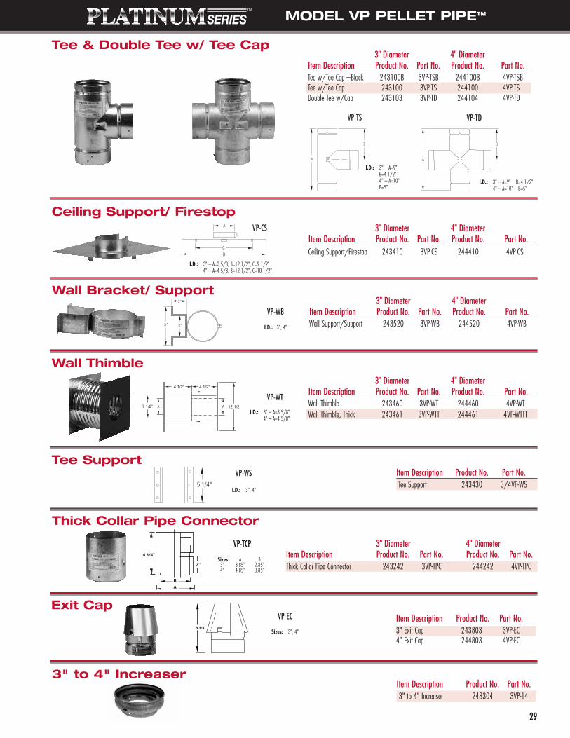
3" Diameter 4" DiameterItem Description Product No. Part No. Product No. Part No.Wall Support/Support 243520 3VP-WB 244520 4VP-WB
3" Diameter 4" DiameterItem Description Product No. Part No. Product No. Part No.Tee w/Tee Cap –Black 243100B 3VP-TSB 244100B 4VP-TSBTee w/Tee Cap 243100 3VP-TS 244100 4VP-TSDouble Tee w/Cap 243103 3VP-TD 244104 4VP-TD
MODEL VP PELLET PIPE™
2929
VP-TS
I.D.: 3" – A=9" B=4 1/2"4" – A=10" B=5"
VP-TD
I.D.: 3" – A=9"B=4 1/2"4" – A=10"B=5"
3" Diameter 4" DiameterItem Description Product No. Part No. Product No. Part No.Ceiling Support/Firestop 243410 3VP-CS 244410 4VP-CS
VP-CS
I.D.: 3" – A=3 5/8, B=12 1/2", C=9 1/2"4" – A=4 5/8, B=12 1/2", C=10 1/2"
VP-WB
I.D.: 3", 4"
VP-WT
I.D.: 3" – A=3 5/8"4" – A=4 5/8"
Item Description Product No. Part No.Tee Support 243430 3/4VP-WS
VP-WS
I.D.: 3", 4"
VP-EC
VP-TCP
Sizes: A B3" 3.85" 2.85"4" 4.85" 3.85"
Sizes: 3", 4"
Tee & Double Tee w/ Tee Cap
Ceiling Support/ Firestop
Wall Bracket/ Support
Wall Thimble
Tee Support
Thick Collar Pipe Connector
Exit Cap
3" Diameter 4" DiameterItem Description Product No. Part No. Product No. Part No.Thick Collar Pipe Connector 243242 3VP-TPC 244242 4VP-TPC
Item Description Product No. Part No.3" Exit Cap 243803 3VP-EC4" Exit Cap 244803 4VP-EC
3" Diameter 4" DiameterItem Description Product No. Part No. Product No. Part No.Wall Thimble 243460 3VP-WT 244460 4VP-WTWall Thimble, Thick 243461 3VP-WTT 244461 4VP-WTTT
Item Description Product No. Part No.3" to 4" Increaser 243304 3VP-14
3" to 4" Increaser
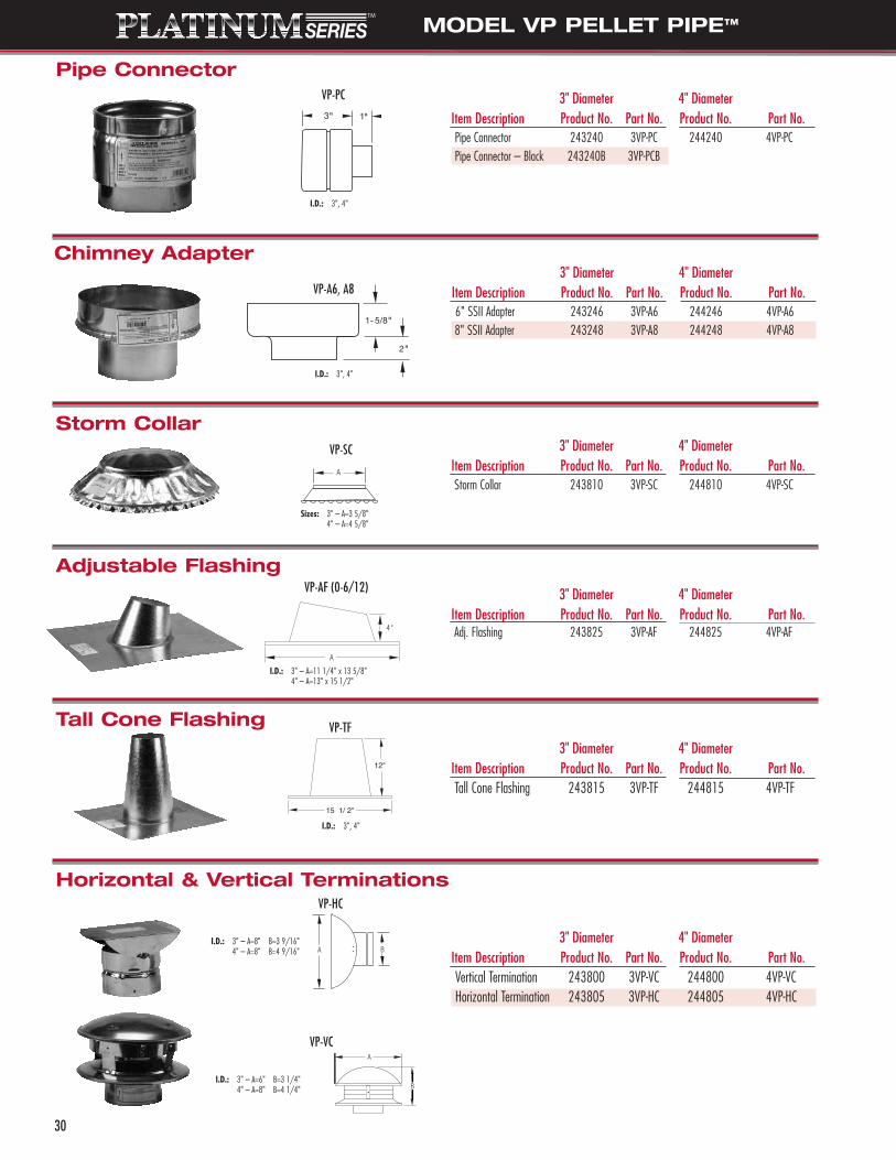
3" Diameter 4" DiameterItem Description Product No. Part No. Product No. Part No.6" SSII Adapter 243246 3VP-A6 244246 4VP-A6 8" SSII Adapter 243248 3VP-A8 244248 4VP-A8
MODEL VP PELLET PIPE™
3" Diameter 4" DiameterItem Description Product No. Part No. Product No. Part No.Vertical Termination 243800 3VP-VC 244800 4VP-VCHorizontal Termination 243805 3VP-HC 244805 4VP-HC
3" Diameter 4" DiameterItem Description Product No. Part No. Product No. Part No.Pipe Connector 243240 3VP-PC 244240 4VP-PCPipe Connector – Black 243240B 3VP-PCB
VP-PC
I.D.: 3", 4"
I.D.: 3", 4"
VP-A6, A8
3" Diameter 4" DiameterItem Description Product No. Part No. Product No. Part No.Storm Collar 243810 3VP-SC 244810 4VP-SC
3" Diameter 4" DiameterItem Description Product No. Part No. Product No. Part No.Adj. Flashing 243825 3VP-AF 244825 4VP-AF
3" Diameter 4" DiameterItem Description Product No. Part No. Product No. Part No.Tall Cone Flashing 243815 3VP-TF 244815 4VP-TF
VP-SC
Sizes: 3" – A=3 5/8"4" – A=4 5/8"
I.D.: 3" – A=11 1/4" x 13 5/8"4" – A=13" x 15 1/2"
VP-AF (0-6/12)
I.D.: 3", 4"
VP-TF
VP-VC
VP-HC
I.D.: 3" – A=6" B=3 1/4"4" – A=8" B=4 1/4"
I.D.: 3" – A=8" B=3 9/16"4" – A=8" B=4 9/16"
Pipe Connector
Chimney Adapter
Storm Collar
Adjustable Flashing
Tall Cone Flashing
Horizontal & Vertical Terminations
30

MODEL VP PELLET PIPE™
3131
COMMON MODEL VP INSTALLATIONS
B FT.
The following illustrations detail the most common types of Model VPinstallations and the variety of parts required.
Horizontal Exit Termination
Through the Ceiling Top Vent
Through the Ceiling Rear Vent
Through theWall Rear Vent

SA08014 03/06
FIELD TECHNICAL SERVICESTo assist users of our products,Metalbestos® venting specialiststhroughout the U.S. conduct fieldinvestigations to help solve unusualventing problems. They also giveassistance on building code and materialsapproval questions.
For complicated projects, our technicalstaff can prepare detailed take-offs fromarchitectural drawings. And, the Selkirkseminars are still another valuable field aidavailable to contractors, building officialsand utility service people.
FACTORY ENGINEERING SERVICESThe Selkirk venting laboratory is one of themost advanced in the world and hasconducted hundreds of tests to solveunusual venting problems. The Selkirkengineering staff provides design servicesfor special product applications and forinstallations requiring complex or unusualmanifold systems.
TECHNICAL AIDSThe Metalbestos® Sizing Handbook is acomprehensive guide to correct ventingwith Metalbestos® gas vent and chimneyparts. This handbook contains detailedvent capacity tables for individual or combined systems, complete design information and illustrations for each typeof venting problem.
In addition, the company provides complete parts catalogs, price sheets and illustrated installation instructions forall products.
Selkirk L.L.C. offers customers a LifetimeLimited Warranty on all MetalbestosVenting Systems, subject to certain warranty conditions.
For a copy of the warranty, please contactus or visit our web site.
www.selkirkusa.com800-992-8368 (VENT)
SELKIRK L.L.C. is a leading manufacturer of venting products for residential, commercial and industrialapplications. Current operations include locations in the United States, Canada and Mexico. SELKIRK L.L.C. hasbeen supplying the finest venting products for over 80 years.
WORLD HEADQUARTERS
P.O. Box 831950Richardson, Texas 75083-1950(800) 992-8368 (VENT)Toll Free Fax: (877) 393-4145www.selkirkusa.com
RESEARCH & DEVELOPMENT
REGISTER & GRILLE R&D2525 Tarpley Road Suite 104Carrollton, Texas 75006(214) 390-8100Fax: (214) 390-8200
VENTING R&DSt. Rt. 93 N. & Sutton Rd.Logan, Ohio 43138(740) 385-5666Fax: (740) 385-2483
MANUFACTURING
UNITED STATES1820 E. Fargo Ave.Nampa, Idaho 83687-6824(208) 467-7411Fax: (208) 467-7412
7571 West Highway 153P.O. Box 427Winters, Texas 79567(325) 754-4571Fax: (325) 754-4764
CANADA1400 California Ave.P.O. Box 160, Brockville, OntarioCanada K6V 5V3(613) 342-6655(800) 267-8178Fax: (613) 342-2735
MEXICOJusto Sierra Y 2 da AvenidaOjinaga, Chihuahua, Mexico011 52 (626) 453-2884/85Fax: 011 52 (626) 453-2886
SALES OFFICES &CUSTOMER SERVICE
UNITED STATESP.O. Box 831950Richardson, Texas 75083-1950(800) 992-VENT (8368)Toll Free Fax: (877) 393-4145
CANADA375 Green RoadStoney Creek, OntarioCanada L8E 4A5(905) 662-6600Fax: (905) 662-5352www.selkirkcanada.com
TECHNICAL SUPPORT
REGISTER, GRILLE & DIFFUSER(214) 390-8100Fax: (214) 390-8200Email: [email protected]
CHIMNEY & VENTINGUS - (800) 848-2149 ext. 2212Fax: (740) 385-2483Email: [email protected] - (888) SELKIRK (735-5475)Fax: (866) 835-9624Email: [email protected]
• Inherent design of Direct-Temp® eliminates fly ash into room• 1" clearance to combustibles• Preheats intake air for more efficient combustion• Gasketed joints eliminate need for messy sealant• One installation includes outside air for combustion• Single stack looks more like a wood burning stove
Selkirk’s revolutionary Direct-Temp® direct vent system for gas appliances is now alsoUL listed for pellet burning appliances. Our two new innovative components will allowyou to convert any pellet appliance into a simpler, cleaner and more efficient direct vent system.
Our engineers set out to surpass the performance requirements of the industry withunique features found only in our direct vent system. Direct-Temp® is ideal for bothsidewall and through-the-roof venting solutions, and has been engineered for optimum appliance performance.
Selkirk’s New Direct Vent System for Pellet Appliances
Metalbestos® Direct Vent Systemfor PELLET STOVES
www.selkirkusa.com • 800.992.8368
Patent Pending
LISTED
Two Components that areRevolutionizing the Venting Industry
ADVANTAGES - DIRECT-TEMP®