Embed Size (px)
Citation preview
Program Title Playful CircuitsProgram Type Topical Weekend ProgramTopic Science Process
Introduction
Participants will take the first step towards becoming aerospace engineers by learning how to wire a simple circuit. Then they will combine art materials with conductive thread, copper tape, LEDs and batteries to create an electric birthday card, party hat, or other seasonally-themed item. This workshop lends itself well to any holiday theme.
Objectives
Students will be able to identify the following components of an electric circuit: energy source, switch, resistance.Students will build series and parallel circuits.Students will create a personalized electric-circuit craft project.
Location/Classroom Notes Recommended for the Space Innovation Workshop
Recommended Age Level Ages 10-13
Background
The activities presented here are mostly “tinkering” activities which lend themselves well to variation and exploration by the participants.For a two-hour workshop, we recommend beginning with Squishy Circuits to have students identify the key components and requirements of an electric circuit. The People Circuit role-play activity reinforces these key ideas while giving students a chance to move around. Choose either activity 3 or activity 4 for more extensive exploration, and provide ample art supplies to allow students to personalize their projects or make them more complex. Younger children or those less experienced with sewing will find activity 3 simpler.
List of Activities
1. Squishy Circuits2. People circuit3. Copper tape circuits and electric cards4. Conductive thread and light-up bracelet
Total Time 2 hoursScientific Concepts and Vocabulary
Electron – a component of an atom, negatively chargedCircuit – a path along which electric current (electrons) can flow. For a continuous flow of electrons, there must be an unbroken path from the energy source (a battery, generator, or wall socket) through the device that uses the power, and back to the energy sourceResistance – something in a circuit which slows the flow of electrons. Sometimes the resistance does useful work; motors and light bulbs fill the role of resistance in a circuit. Sometimes resistance is added to slow the flow of electrons so that the electric devices are not overwhelmed with current.Short Circuit – a circuit with very little resistance. For example, you create a short circuit when you connect the positive and negative ends of a battery together directly with wire. The flow of electrons (current) in a short circuit is very fast and can produce a lot of heat.Series Circuit – a circuit in which there is a single path through all the devices that use power. In a series circuit, the current passing through each electrical device is
Science World British ColumbiaPage 1 of 12
the same. The devices share the circuit’s energy. Three bulbs linked in series will be dimmer than a single bulb in the same circuit.Parallel Circuit – a circuit in which there are multiple paths. Each device connected in parallel receives the full energy of the source. Three bulbs linked in parallel will each be as bright as a single bulb in the same circuit. However, a battery-powered circuit with three bulbs in parallel will use up the battery faster than a single bulb attached to the same battery.Switch – a method of breaking and re-making the circuit to control the flow of electrons.Conductor – an item or material that allows electrons to flow through it easily is a conductor.Insulator – An item or material that does not easily allow electrons to flow through it is an insulator. Note that a material which is an insulator in a low-voltage circuit will become a conductor at a higher voltage. So a person won’t conduct enough current to be part of a squishy circuit, but will conduct plenty of current if they come in contact with a wall outlet.Voltage – a measurement of the energy supplied per unit charge (this quantity is called electric potential) by an energy source. The coin cell batteries in this workshop supply 3V of potential. An AA battery supplies 1.5V.LED – Light Emitting Diodes function as tiny light bulbs. They light up due to the movement of electrons through a semiconductor material. A full explanation can be found at: http://electronics.howstuffworks.com/led.htm
For the purposes of this workshop, it is important to know that LEDs are directional; they create light only when current flows through them in one direction. It’s also worth knowing that too much voltage will destroy the LED. The energy that passes through an LED is usually regulated by adding resistance to the circuit, which is why we make sure that playdough is always part of a squishy circuit.
References
Squishy Circuits were created by AnnMarie Thomas at the University of St. Thomas in St. Paul Minnesota http://courseweb.stthomas.edu/apthomas/SquishyCircuits/
The paper circuits activities here are based on those developed by High-Low Tech, a research group at the MIT Media Lab.
Other Resources
For more ideas and tips related to all these activities, see the Tinkering Studio’s site at http://tinkering.exploratorium.edu/
The Art of Tinkering by Karen Wilkinson and Mike Petrich is a beautiful and inspirational book full of electrical and non-electrical “making” projects.
Activity # 1Activity Title Squishy CircuitsActivity Time 30 minutes
Science World British ColumbiaPage 2 of 12
Activity Type Small group activity
Activity IntroductionThe friendly and simple materials in this activity encourage students to explore the basic principles of electric circuits.
Materials
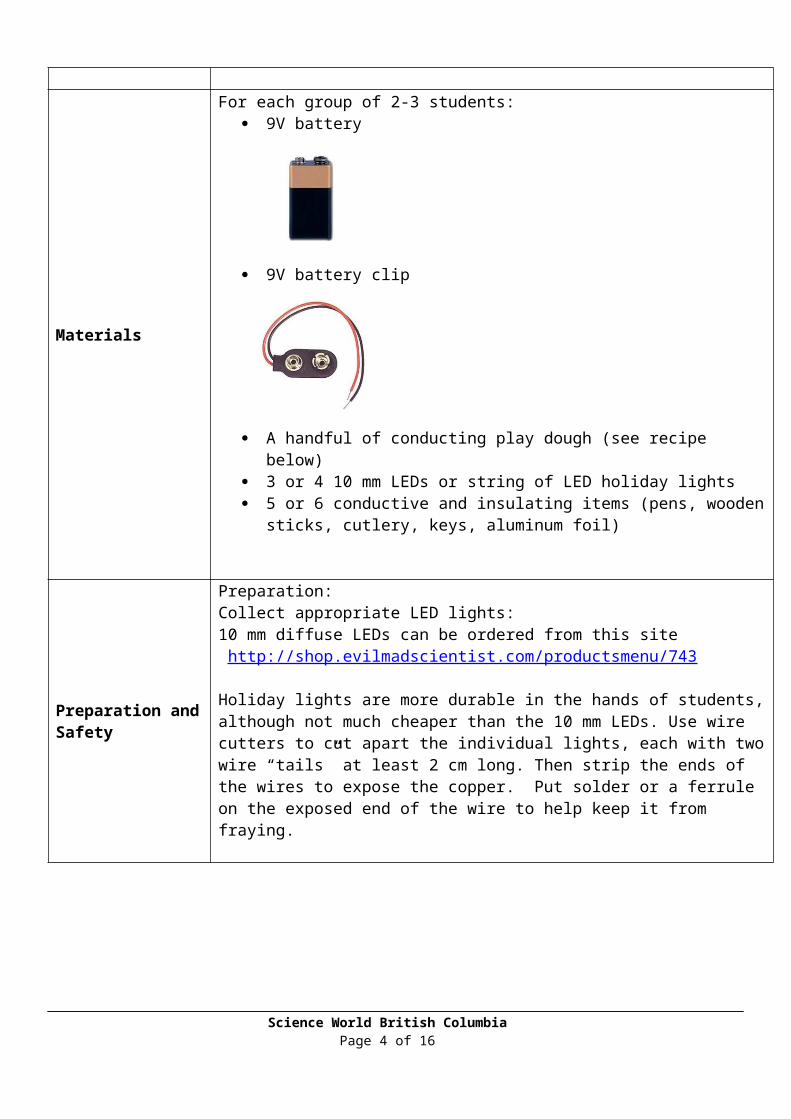
For each group of 2-3 students: 9V battery
9V battery clip
A handful of conducting play dough (see recipe below) 3 or 4 10 mm LEDs or string of LED holiday lights 5 or 6 conductive and insulating items (pens, wooden sticks, cutlery, keys,
aluminum foil)
Preparation and Safety
Preparation:Collect appropriate LED lights:10 mm diffuse LEDs can be ordered from this site http://shop.evilmadscientist.com/productsmenu/743
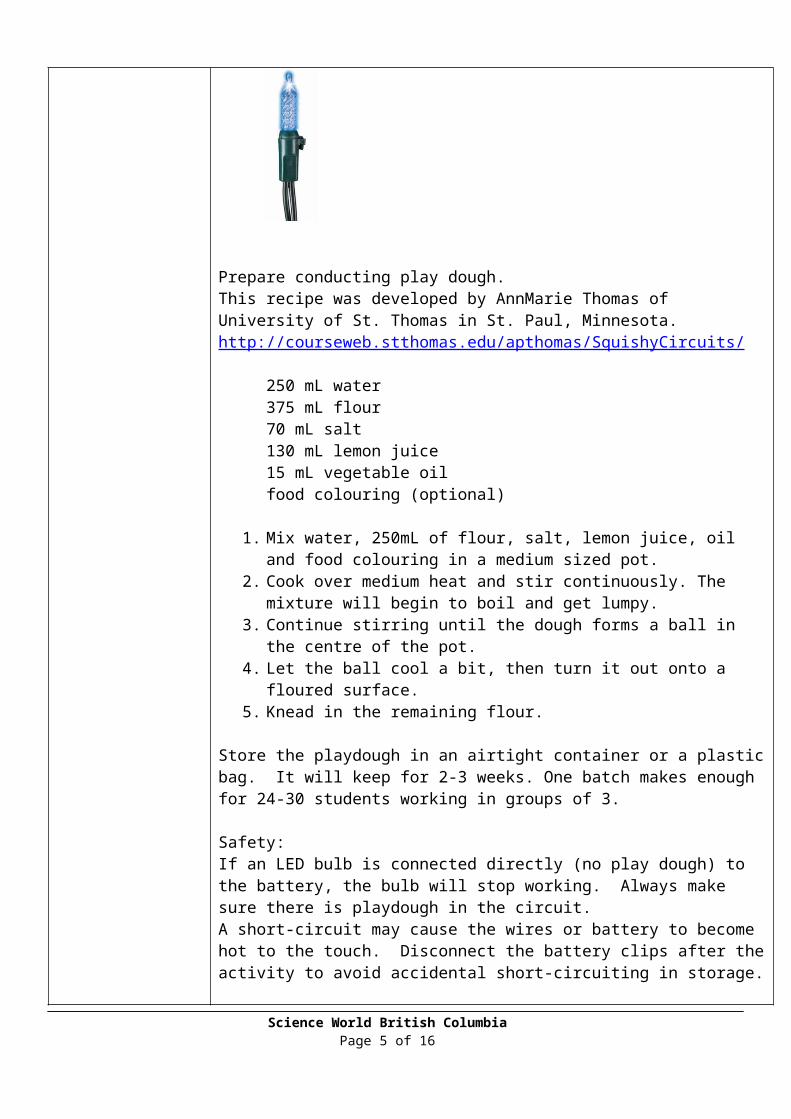
Holiday lights are more durable in the hands of students, although not much cheaper than the 10 mm LEDs. Use wire cutters to cut apart the individual lights, each with two wire “tails” at least 2 cm long. Then strip the ends of the wires to expose the copper. Put solder or a ferrule on the exposed end of the wire to help keep it from fraying.
Prepare conducting play dough. Science World British Columbia
Page 3 of 12
This recipe was developed by AnnMarie Thomas of University of St. Thomas in St. Paul, Minnesota. http://courseweb.stthomas.edu/apthomas/SquishyCircuits/
250 mL water375 mL flour70 mL salt130 mL lemon juice15 mL vegetable oilfood colouring (optional)
1. Mix water, 250mL of flour, salt, lemon juice, oil and food colouring in a medium sized pot.
2. Cook over medium heat and stir continuously. The mixture will begin to boil and get lumpy.
3. Continue stirring until the dough forms a ball in the centre of the pot.4. Let the ball cool a bit, then turn it out onto a floured surface.5. Knead in the remaining flour.
Store the playdough in an airtight container or a plastic bag. It will keep for 2-3 weeks. One batch makes enough for 24-30 students working in groups of 3.
Safety: If an LED bulb is connected directly (no play dough) to the battery, the bulb will stop working. Always make sure there is playdough in the circuit. A short-circuit may cause the wires or battery to become hot to the touch. Disconnect the battery clips after the activity to avoid accidental short-circuiting in storage.
What to Do
1. Organize students into pairs or groups of 3. Each group gets a handful of play dough, a battery with a clip, and one LED light bulb.
2. Challenge the students to light the bulb without touching any metal part to any other metal part. They should only use play dough to make the electrical connection.
3. As each group is successful, invite them to take on further challenges, for example:
a. Light two or three bulbs.b. Create a playdough switch that will turn the bulbs on and off.c. Create a switch that will turn off one of two lights (but not the other).d. Create a parallel circuit with two bulbs.e. Create a series circuit with two bulbs.
4. (optional) Introduce other items into the circuit to find out whether they conduct current. Good choices are wooden sticks, pieces of aluminum foil, keys, pens and pencils, etc.
Key Questions 1. Does the circuit work if you turn the LED around? (The LED works only when the current flows in one particular direction. Try turning the LED and/or swapping
Science World British ColumbiaPage 4 of 12
the positive and negative leads from the battery to test this.)2. Does (a pencil, a key, a piece of foil) conduct current? How do you know? (The
item is a conductor if the bulb lights with the item as part of the circuit.)
Activity # 2Activity Title People CircuitActivity Time 15 minutesActivity Type Whole group activity
Activity Introduction
In this model, the students are the electrons, and the energy provided by the battery is represented by candies. The current is the amount of charge (electrons) moving in the circuit per unit time, measured in amperes.
A resistance slows the electric current; resistance is represented in this model by having the students climb over a chair. In order to increase the electrical current, we must speed up the movement of electrons; we do this in the model by adding extra energy in the form of extra candies (in a real circuit, you would add more batteries, or use a higher-voltage battery).
Students will feel warmer as they speed up, which mimics what takes place along a wire in a real circuit: as electrons pass through a resistance they release energy as heat.
Materials
students stool, chair or box masking tape box of small candies (check for allergies and food restrictions)
Preparation and Safety
Preparation:Use the masking tape to outline a circle on the classroom floor.
Safety:Be aware of students’ allergies or food restrictions and choose candies appropriately.
What to Do 1. Students form a circle (along the masking tape) to represent the wire. 2. Explain that the students are electrons. There are always electrons in the wire,
and they are always moving randomly, a little bit in every direction.3. Choose one of the students to be the power source (battery). This student
holds a box of candy – the candies represent “energy”. The closest student to the battery moves forward to get a candy. The other students follow immediately, moving along the “wire” in a loop.
4. As the electrons pass the battery, they get energy (candy).5. Next pick someone to be a switch. The switch, when off, will completely stop
Science World British ColumbiaPage 5 of 12
the electron movement. The switch could either put up their hand, or turn to the side to represent “off”.
6. Have the circuit practice on and off a couple times. Note that when the switch is off, all the electrons stop at once (they don’t pile up somewhere).
7. Now put a stool (or a chair or a box) somewhere along the “wire”. This represents a resistance. The electrons have to climb over the stool to move forward. The whole electron chain will slow down, showing that the current slows down when there is a resistance.
8. How could we convince the electrons to move faster through the resistance? We could hand out more candy – maybe two candies each time they pass the energy source! This represents a greater voltage (more energy per electron).
9. When the box of candies is empty, the battery is “dead” and the current will stop. Note that the battery gets used up faster if you pass out more energy per electron.
Key Questions1. How could we increase the current (in other words, how can we make the
electrons move faster)? (Add more energy per electron)
Activity # 3Activity Title Paper CircuitsActivity Time 30 minutesActivity Type Individual activity
Activity Introduction In this activity students make circuits with LEDs, conductive copper tape, and 3V “coin” batteries. The circuits can be incorporated into greeting cards or art projects.
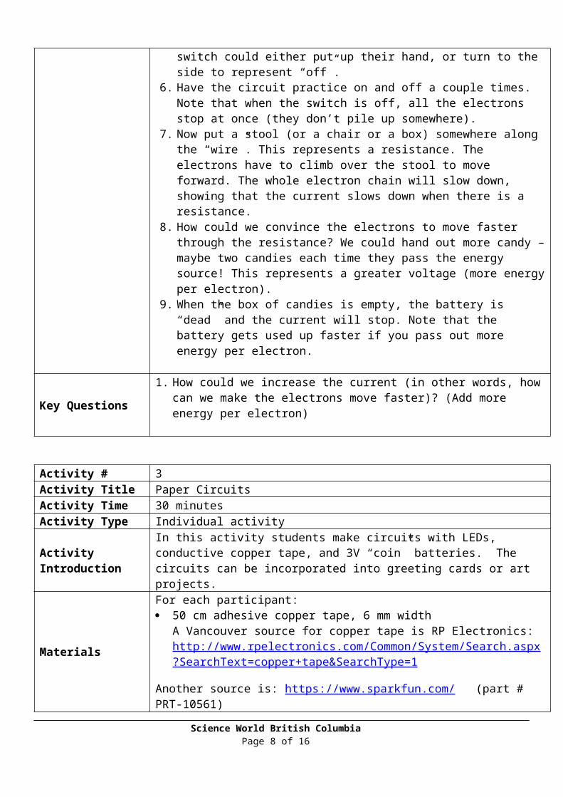
Materials For each participant: 50 cm adhesive copper tape, 6 mm width
A Vancouver source for copper tape is RP Electronics: http://www.rpelectronics.com/Common/System/Search.aspx?SearchText=copper+tape&SearchType=1
Another source is: https://www.sparkfun.com/ (part # PRT-10561)
one piece of paper about 10 cm square (optional) circuit template, (Topical Weekend Program - Playful Circuits
Templates.docx) one 3V coin battery, size 2032 or CR1220 one or two LEDs
Science World British ColumbiaPage 6 of 12
one binder clip
adhesive tape needle-nose pliers
coloured paper and art supplies for making a card
Preparation and Safety Cut copper tape into 50 cm lengths.
What to Do 1. Remind students of the essential parts of a circuit: there must be an energy source and a path for the current to follow through the resistance. The circuit must form a circular path from the energy source (battery) through the resistance and back to the source.
2. Explain that the path in this circuit will be made of copper tape.3. If you are using a template (Weekend Program - Playful Circuits templates.docx),
pass out the templates to the students and have them trace the circuit path with their fingers.
4. If you are not using a template, have students draw a square path on the paper to represent the circuit, noting where the light will be and where the battery will be.
5. Check the path for completeness before giving students the copper tape.6. Students use the tape to cover the path they have drawn, leaving a space for the
LED bulb and for the battery.7. Demonstrate that the coin battery has a positive and a negative side. Show
students that the long lead of the LED must connect to the positive side of the battery and the short end must connect to the negative side.
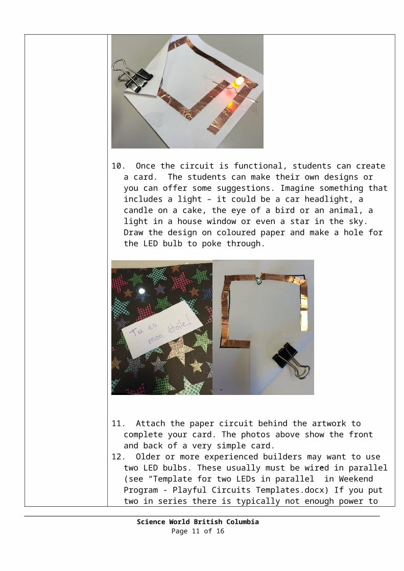
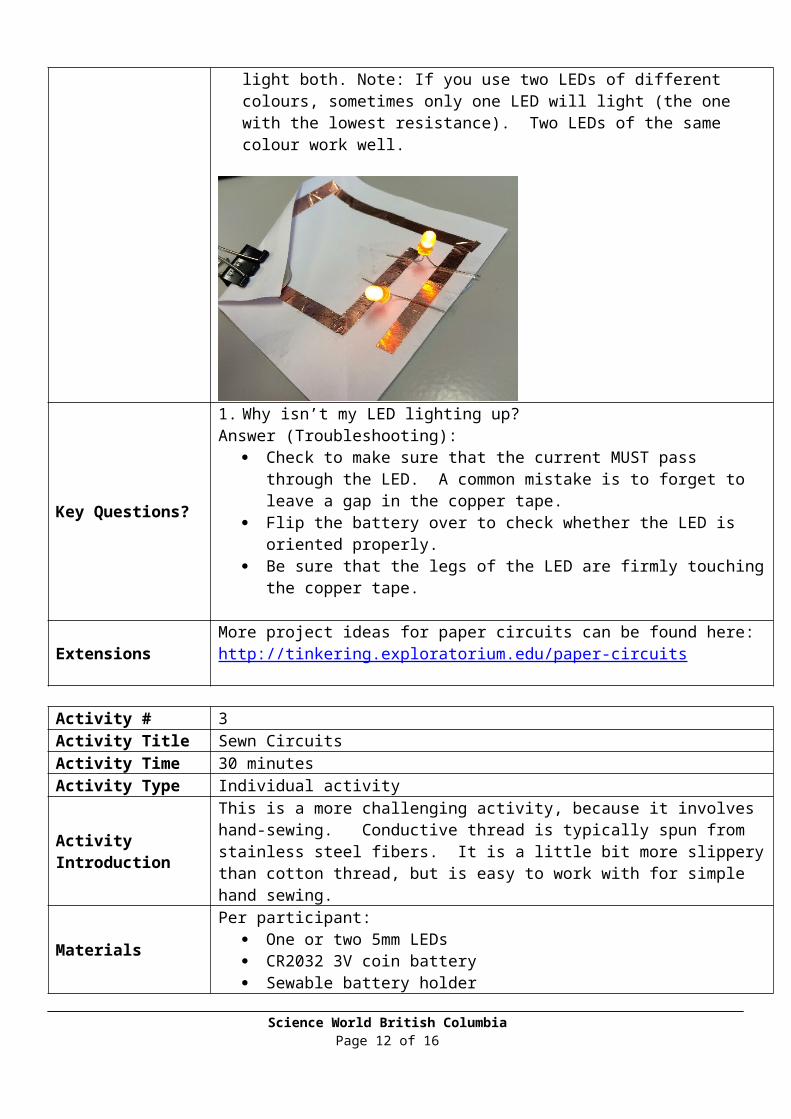
8. Students can now use regular adhesive tape to attach their LED to their circuit.9. Finally, students should fold the paper so that one end of the circuit connects to
the positive side of the battery and one end to the negative side. The binder clip holds the battery in place so that the bulb stays on. These photos show the finished product.
Science World British ColumbiaPage 7 of 12
10. Once the circuit is functional, students can create a card. The students can make their own designs or you can offer some suggestions. Imagine something that includes a light – it could be a car headlight, a candle on a cake, the eye of a bird or an animal, a light in a house window or even a star in the sky. Draw the design on coloured paper and make a hole for the LED bulb to poke through.
Science World British ColumbiaPage 8 of 12
11. Attach the paper circuit behind the artwork to complete your card. The photos above show the front and back of a very simple card.
12. Older or more experienced builders may want to use two LED bulbs. These usually must be wired in parallel (see “Template for two LEDs in parallel” in Weekend Program - Playful Circuits Templates.docx) If you put two in series there is typically not enough power to light both. Note: If you use two LEDs of different colours, sometimes only one LED will light (the one with the lowest resistance). Two LEDs of the same colour work well.
Key Questions?
1. Why isn’t my LED lighting up? Answer (Troubleshooting):
Check to make sure that the current MUST pass through the LED. A common mistake is to forget to leave a gap in the copper tape.
Flip the battery over to check whether the LED is oriented properly. Be sure that the legs of the LED are firmly touching the copper tape.
ExtensionsMore project ideas for paper circuits can be found here:http://tinkering.exploratorium.edu/paper-circuits
Activity # 3Activity Title Sewn CircuitsActivity Time 30 minutesActivity Type Individual activity
Activity IntroductionThis is a more challenging activity, because it involves hand-sewing. Conductive thread is typically spun from stainless steel fibers. It is a little bit more slippery than cotton thread, but is easy to work with for simple hand sewing.
Materials Per participant: One or two 5mm LEDs CR2032 3V coin battery Sewable battery holder https://www.sparkfun.com/products/8822
Science World British ColumbiaPage 9 of 12
Strip of felt or fleece fabric approximately 25cm x 5 cm About one metre of conductive thread
https://www.sparkfun.com/products/11791
One sew-on metal snap fastener (From a sewing supplies store, these are
typically about .5cm in diameter and sold in packages of 10 or more)
To share: scissors sewing needles (and threaders, optional) extra materials for decoration – fabric scraps, fabric paint, etc. needle-nose pliers permanent felt marker
Preparation and Safety
Preparation:Ensure that your working space has good light. Keep all the small parts in containers so they do not drop and vanish.
What to Do 1. Remind students of the essential parts of a circuit: there must be an energy source and a path for the current to follow through the resistance. The circuit must form a circular path from the energy source (battery) through the resistance and back to the source.
2. Explain that the path in this circuit will be made of conductive thread. The energy source is a coin battery, and the snap fastener is a switch that can open and close the circuit.
3. You could choose to have students work at their own pace, following printed instructions (photos or finished samples will be helpful). Or you could lead the group through the project step by step.
Prepare your LED to be sewable.1. The longer leg of the LED must be attached to the positive side of the
Science World British ColumbiaPage 10 of 12
battery. Before you modify your LED, use a permanent marker to colour the positive leg.
2. With needle-nose pliers, bend each leg of the LED into a small loop. Trim off the excess wire.
Use conductive thread to do all the sewing.1. Wrap the fabric around your wrist to find the best length for a bracelet.
With the fabric around your wrist, the ends should overlap by 1-2 cm.2. Attach one side of the snap fastener by sewing it near one of the short ends
of the fabric strip.3. Do not cut the thread. Sew a running stitch for about 5 cm.4. Do not cut the thread. Sew one end of the battery holder to the fabric at the
end of your 5 cm of running stitch. Make a knot and cut the thread.5. Sew the other end of the battery holder to the fabric. Do not cut the thread.
Identify the positive and negative terminals of the battery holder.6. Continue in running stitch until you reach the place where you’d like to
locate the LED.7. Being very careful that the positive leg of the LED is facing the positive
terminal of the battery holder, sew one loop of the LED to the fabric. Tie a knot and cut the thread.
8. Sew the second loop of the LED to the fabric. Do not cut the thread.9. Continue in running stitch until you reach the other short end of the fabric.
Do not cut the thread.10. Sew the second part of the snap fastener to the back of the fabric.
Test your circuit1. Insert a battery into the battery holder.2. Snap the two parts of the snap fastener together. The LED should light up.
Key Questions 1. Where does the electric current flow? (From the battery, through the thread to Science World British Columbia
Page 11 of 12
the LED, from the LED through more thread to the snap, then to the second part of the snap and back to the battery.)
2. Why isn’t my LED lighting up?Answer (Troubleshooting):
a. Be sure that the LED is oriented so that the positive leg of the LED is connected to the positive side of the battery.
b. Be sure that the thread makes good contact with the metal in the battery holder, LED and snap fastener.
Extensions
Once students have a working circuit bracelet, they can add seasonally-themed decorations. For example, they could create a flower with a light-up centre.There are many more suggestions for fabric circuits at this site:http://tinkering.exploratorium.edu/sewn-circuitsand here:http://highlowtech.org/?p=1003
Science World British ColumbiaPage 12 of 12