Embed Size (px)
Citation preview

PLEASE PRINT AND INCLUDE, AS APPENDICES A, B, C & D RESPECTIVELY, THE LATEST REVISIONS OF THE
FOLLOWING DOCUMENTS:
965-0006 400-2453 400-2467 965-0008
DISCARD THIS PAGE AFTER PRINTING!

OPERATION AND MAINTENANCE MANUAL
FOR
VERTEXRSI MODEL 2.4M SM-LT MULTI-BAND 2.4-METER TRANSPORTABLE
EARTH STATION SATELLITE TERMINAL
600-1125
Revision C October 5, 2004
SATCOM Technologies 2600 N. Longview St., Kilgore, TX USA 75662-6842
Phone (903) 984-0555 FAX (903) 984-1826 www.gdsatcom.com
"EXPORT CONTROL WARNING - the disclosure of this document or its contents to non-U.S. persons, or the transmission of its contents outside the United States must be in compliance with U.S. Export Laws and Regulations. The bearer of this document is under obligation to know the applicable restrictions for the dissemination of its contents that relate to U.S. Export Laws and Regulations or any other U.S. government approvals".


600-1125C i
SATCOM TECHNOLOGIES CONFIDENTIAL AND PROPRIETARY
All computer software, technical data or other information pertaining to the equipment covered by this document is considered proprietary by SATCOM Technologies. Such information transmitted in this document or related documents is for the benefit of SATCOM Technologies customers and is not to be disclosed to other parties verbally or in writing without prior written approval of SATCOM Technologies. Additionally, this document may not be reproduced in whole or in part without written consent from SATCOM Technologies.
C EC #04-0927 9/29/04 RKH JTB JTB
B Changes to section 3, add new sections 4 and 5 4/8/04 JDT JTB DLB
A Original release 1/26/04 JDT JTB DLB
REV. DESCRIPTION DATE WRITER CHK. APPR.
600-1125C ii
Use of WARNINGS, CAUTIONS, etc.
Warnings, Cautions and other notes are included throughout this document to provide necessary information. IGNORING WARNINGS, CAUTIONS AND OTHER NOTES MAY RESULT IN DAMAGE TO THE PRODUCT, INJURY, OR IN EXTREME CASES, DEATH. You should know the use of Warnings, Cautions and other markings. Definitions are:
WARNING! HIGHLIGHTS AN INSTALLATION, OPERATING OR MAINTENANCE PROCEDURE, PRACTICE, CONDITION, STATEMENT, ETC., WHICH, IF NOT STRICTLY OBSERVED, COULD RESULT IN INJURY TO OR DEATH OF PERSONNEL.
CAUTION! HIGHLIGHTS AN INSTALLATION, OPERATING OR MAINTENANCE PROCEDURE, PRACTICE, CONDITION, STATEMENT, ETC., WHICH, IF NOT STRICTLY OBSERVED, COULD RESULT IN DAMAGE TO OR DESTRUCTION OF EQUIPMENT OR THE LOSS OF MISSION EFFECTIVENESS OR LONG TERM HEALTH HAZARDS TO PERSONNEL.
Important: Highlights an essential installation, operating or maintenance procedure, practice, condition or statement, which, if heeded, will ensure efficiency and/or safety of said procedures.
Note: Highlights an installation, operating or maintenance procedure, practice, condition or statement, which, if heeded, could enhance efficiency and/or safety of said procedures.
ESD: The Electrostatic Sensitive Device (ESD) appears at the beginning of any procedure or procedural step that includes the handling of equipment sensitive to damage from electrostatic discharge.
General Warnings and Cautions are also provided at the front of the document. These Warnings and Cautions should be read by anyone who is involved with installation, has access to the equipment or is assigned to perform maintenance on the equipment.

600-1125C iii
CAUTIONARY NOTICE
Although SATCOM Technologies has attempted to detail in this document all areas of possible danger to personnel in connection with the use of this equipment, personnel should use caution when installing, operating and servicing this equipment. Care should be taken to avoid electrical shock, whether the hazard is caused by design or malfunction. SATCOM Technologies is specifically not liable for any damage or injury arising from a technician’s failure to follow the instructions contained in this document or his failure to exercise due care and caution in the installation, operation and service of this equipment. SATCOM Technologies shall not be responsible for injury or damage resulting from improper procedures or from the use of improperly trained or inexperienced personnel performing such tasks.
This document is intended as a general guide for trained and qualified personnel who are aware of the dangers of handling potentially hazardous electrical and electronic circuits. This document is not intended to contain a complete statement of all safety precautions that should be observed by personnel in using this or other electronic equipment.
ELECTRICAL HAZARDS
The antenna and feed system supplied by SATCOM Technologies is designed to be integrated with various types of electronic equipment. This system, if integrated with high power amplifiers or traveling wave tubes, will be capable of transmitting microwave energy at varying power levels. If transmitting microwave power, SATCOM Technologies cautions the end-user to review all applicable local, federal and international regulations and to comply with all such regulations in the operation and maintenance of the integrated system.
The electrical currents and voltages associated with this equipment, whether supplied by SATCOM Technologies or others, are dangerous. Personnel must at all times observe safety regulations.
• It is recommended that a lockout/tagout process be utilized while servicing the antenna system. In the United States, see OSHA 1910.147.
• Always disconnect power before opening covers, doors, enclosures, gates, panels or shields.
• Always use grounding sticks and short out high voltage points before servicing.
• Do not remove, short-circuit or tamper with interlock switches on access covers, doors, enclosures, gates, panels or shields.
• Keep away from live circuits.
• Know your equipment and do not take risks.
• Always remove all power to the system prior to working on the antenna, the reflector assembly, the reflector backup assembly or the feed assembly.
• Always tag all circuits noting that the power is OFF, the date and your name, prior to commencing any work on that system.
In case of emergency, be sure that power is disconnected.

600-1125C iv
POTENTIAL DAMAGE TO ANTENNA
The antenna limit switches and resolvers have been pre-set to allow maximum antenna performance. Any subsequent adjustment may jeopardize antenna performance and/or result in damage to the antenna.
SAFETY NOTICE
The following safety procedures are listed to remind those performing any work on the antenna system that safety rules must be observed. Failure to observe safety rules may result in serious injury or death. Always work safely and in accordance with established procedures.
• It is recommended that a lockout/tagout process be utilized while servicing the antenna system. In the United States, see OSHA 1910.147.
• Care shall be taken in all operations to safeguard other people as well as property and to comply with all local safety procedures as established by the customer’s site representative, as well as local building codes and fire protection standards.
• All persons performing work on the antenna system shall also comply with the Occupational Safety and Health Act (OSHA) standards and all other federal state and local laws, ordinances, regulations and codes relating to designated work.
• Unless the customer’s representative on site specifically designates an individual responsible for site safety, the SATCOM Technologies Site Supervisor shall be responsible for and establish a site safety program for the SATCOM Technologies installation work. The site safety program shall incorporate all SATCOM Technologies safety procedures and requirements
• Never make internal adjustments or perform maintenance or service when alone or fatigued.
ELECTROMAGNETIC RADIATION
• It is recommended that a lockout/tagout process be utilized while servicing the antenna system. In the United States, see OSHA 1910.147.
• Do not stand in the direct path of the feed system when the system is transmitting!
• Do not work on the feed system when the system is on!
ALWAYS WORK SAFELY!
600-1125C v
TABLE OF CONTENTS
1.0 INTRODUCTION ..........................................................................................................1-1 1.1 Description....................................................................................................................1-2 1.2 Manual Organization.....................................................................................................1-3 1.3 Safety Considerations...................................................................................................1-3 1.4 Electrical/Mechanical Specifications .............................................................................1-4 1.5 Transporting..................................................................................................................1-6 1.6 Operation at Low Elevation Angles...............................................................................1-6
2.0 EMERGENCY PROCEDURES ....................................................................................2-1 2.1 Hand Crank Procedure .................................................................................................2-1
3.0 INSTALLATION............................................................................................................3-1 3.1 General Interface Requirements...................................................................................3-1 3.2 Shipping Configuration..................................................................................................3-1 3.3 Mechanical Interface.....................................................................................................3-6 3.4 RF Interface ..................................................................................................................3-8 3.5 Controls.........................................................................................................................3-8 3.6 Installation Procedure ...................................................................................................3-9
4.0 AZIMUTH POSITION SYSTEM....................................................................................4-1 4.1 Azimuth Bearing............................................................................................................4-1 4.2 Azimuth Gear Box.........................................................................................................4-1 4.3 Azimuth Motor...............................................................................................................4-2 4.4 Azimuth Cable Drive .....................................................................................................4-3
5.0 ELEVATION POSITION SYSTEM ...............................................................................5-1 5.1 Elevation Gear Box.......................................................................................................5-1 5.2 Elevation Motor .............................................................................................................5-2 5.3 Elevation Cable Drive ...................................................................................................5-2
6.0 MAINTENANCE ...........................................................................................................6-1 6.1 Preventative Maintenance ............................................................................................6-1 6.2 General Maintenance Procedures ................................................................................6-7 6.3 Control System Information ..........................................................................................6-9
7.0 GENERAL OPERATION..............................................................................................7-1 7.1 Feed Boom ...................................................................................................................7-1 7.2 Multi-Band Feed Systems.............................................................................................7-2
8.0 WARRANTY.................................................................................................................8-1 APPENDIX A. 965-0006: PROCEDURE FOR THE PREPARATION OF NON-PAINTED FERROUS METAL SURFACES AND APPLICATION OF A RUST-INHIBITIVE COATING .. A-1 APPENDIX B. 400-2453: FEED WINDOW REPLACEMENT FOR X-BAND FEED MODELS WITH CORRUGATED HORN .................................................................................................. B-1 APPENDIX C. 400-2467: FEED WINDOW REPLACEMENT FOR L/S BAND FEED MODELS WITH CORRUGATED HORN .................................................................................................. C-1 APPENDIX D. 965-0008: PROCEDURE FOR SETTING ELEVATION STOW SWITCH TO CREATE ANTENNA PRELOAD UPON STOWING................................................................. D-1

600-1125C vi
LIST OF FIGURES
Figure 1-1. VertexRSI Model 2.4M SM-LT Antenna .................................................................1-1 Figure 2-1. Hand Crank Input Shaft Locations..........................................................................2-1 Figure 2-2. Hand Crank Input Shaft Caps.................................................................................2-2 Figure 2-3. Hand Crank Input Shafts ........................................................................................2-3 Figure 2-4. Polarization Drive Motor .........................................................................................2-4 Figure 3-1. Feed Boom Secured to Reflector ...........................................................................3-2 Figure 3-2. Lag Bolt Location....................................................................................................3-2 Figure 3-3. Antenna Center of Gravity Locations......................................................................3-3 Figure 3-4. Positioning Forklift (view from front of antenna) .....................................................3-4 Figure 3-5. Lifting with Hoist .....................................................................................................3-5 Figure 3-6. Antenna Mounting Requirements (Bearing Interface) ............................................3-6 Figure 3-7. Wear Plate Locations .............................................................................................3-7 Figure 3-8. Equipment Bays .....................................................................................................3-8 Figure 3-9. Umbilical Cables.....................................................................................................3-9 Figure 3-10. Silicone Bead........................................................................................................3-9 Figure 3-11. Cable Routing.....................................................................................................3-10 Figure 3-12. Antenna Positioning............................................................................................3-10 Figure 3-13. Antenna Stabilization..........................................................................................3-11 Figure 3-14. Bolt Installation ...................................................................................................3-11 Figure 4-1. Azimuth Motor and Gearbox...................................................................................4-1 Figure 4-2. Internal Components of Gear Reducer...................................................................4-2 Figure 4-3. Azimuth Bearing Cable Connections......................................................................4-3 Figure 5-1. Top View of Positioner............................................................................................5-1 Figure 5-2. Elevation Spring Block............................................................................................5-3 Figure 6-1. Maintenance Locations...........................................................................................6-2 Figure 6-2. Maintenance Locations (Gearboxes)......................................................................6-3 Figure 6-3. Maintenance Locations (Flexible Waveguide)........................................................6-4 Figure 6-4. Feed Window..........................................................................................................6-5 Figure 6-5. Feed Boom Struts...................................................................................................6-6 Table 6-2. Torque Values .........................................................................................................6-7 Figure 6-6. Serial Number Plate Location.................................................................................6-8 Figure 7-1. Deploy/Stow Configurations ...................................................................................7-1 Figure 7-2a. Locating Pins ........................................................................................................7-3 Figure 7-2b. Locating Pins ........................................................................................................7-3 Figure 7-3. Feed Attachment to Pallet ......................................................................................7-4 Figure 7-4. Waveguide Cap ......................................................................................................7-5 Figure 7-5. Attach Waveguide ..................................................................................................7-6 Figure 7-6. Installed Waveguide ...............................................................................................7-7 Figure 7-7. Waveguide Cap Storage ........................................................................................7-7 Figure 7-8a. Waveguide Attachment ........................................................................................7-8 Figure 7-8b. Waveguide Attachment ........................................................................................7-8 Figure 7-9. Storage Location of Multi-Conductor Cable............................................................7-9 Figure 7-10. Multi-Conductor Cable Installation......................................................................7-10 Figure 7-11. Operating Position ..............................................................................................7-11
LIST OF TABLES
Table 1-1. Model 2.4M SM-LT Antenna Specifications.............................................................1-5 Table 6-1. Maintenance Schedule ............................................................................................6-1

600-1125C 1-1
1.0 INTRODUCTION This manual provides information and instructions for installation, operation, and maintenance of the VertexRSI Model 2.4M SM-LT (Single-Offset Lightweight Mobile) Earth Station Satellite Antenna. This antenna is intended for mobile applications on van-type vehicles or trailers and provides for simple, automated deployment and stowing capability. It is a high-performance broadband, offset-feed type antenna that meets the FCC two-degree spacing requirements. Design features include: superior RF performance, rugged construction, and state-of-the-art drive components that achieve excellent signal pointing while providing a compact, aerodynamic structure for mounting above the roofline.
Figure 1-1. VertexRSI Model 2.4M SM-LT Antenna
600-1125C 1-2
1.1 Description The VertexRSI Model 2.4M SM-LT antenna may simply be described as having four (4) major components; reflector, pedestal, feed system and control system. The VertexRSI model 2.4M SM-LT employs the latest in composite technology in construction. The reflector is constructed using carbon-fiber-reinforced-polymer (CFRP) laminates separated by a structural foam core. This reflector is permanently bonded and supported by a back-beam (or structural spine) that is also formed using CFRP construction. The composite construction of these components results in a low-weight, high-stiffness structure. The back-beam aids in transferring loads from the reflector to the cable-drive positioning system. The pedestal provides the azimuth and elevation drive mechanisms as well as the structural tie to the vehicle/trailer. The pedestal utilizes an elevation-over-azimuth capstan cable drive that results in a highly accurate and repeatable drive mechanism. Both azimuth and elevation drives contain adjustable-backlash worm gearboxes that provide low-backlash operation at all loading conditions. Direct current (DC) motors with tachometer feedback are provided on both axes. These motors are extremely durable and reliable. Coupled with the capstan cable-drive, the drive system of the VertexRSI 2.4M SM-LT is virtually unparalleled in accuracy and precision. The feed system of the VertexRSI 2.4M SM-LT consists of interchangeable, band-specific microwave components located at the focus of the main reflector. The feed is a wide-band device that permits simultaneous transmission and reception operation, each in orthogonal planes. The alignment of the feed polarization angle (linear operation) for proper orientation to the desired satellite constitutes a third axis of movement in addition to azimuth and elevation. The feed head contains a miniature DC motor drive system for this purpose. The polarization drive system also contains a potentiometer that is calibrated for accurate position feedback to the applicable control system. The feed is supported at the reflector focus by a self-stowing feed-boom consisting of two (2) main spars (arms) supported by pressurized gas cylinder struts. The struts are affixed to the aforementioned reflector/back-beam structure. The waveguide supplying the feed with the RF power runs along the feed-boom arms with flexible connecting sections or rotary joints (configuration specific) which permit polarization angle adjustment at the feed and pivoting of the feed-boom relative to the stowed position. The feed is the visible portion of a system of components that may include (depending on the options selected) filtering, switching, and electronics. This RF package (module) may be located within the feed-boom, interior to the vehicle, or beside the antenna positioning system. The VertexRSI 2.4M SM-LT can be configured with various control systems. For specific control system operation, function, and maintenance, please see the applicable Antenna Control System Operation and Maintenance Manual.

600-1125C 1-3
1.2 Manual Organization This operation and maintenance manual is organized to describe VertexRSI Model 2.4M SM-LT antenna components. The information is divided into sections as follows:
Section 1 Introduction provides information on the Model 2.4M SM-LT antenna
components and their interconnection in the system, how this O&M manual is organized and Safety Considerations and Specifications for the Model 2.4M SM-LT antenna.
Section 2 Emergency Procedures provides detailed procedures for performing Azimuth, Elevation and Polarization hand crank Operations.
Section 3 Installation provides information on Mechanical Interface, RF Interface, Electrical Interface and step-by-step procedures for installing the Model 2.4M SM-LT antenna.
Section 4 Information detailing the azimuth positioning system. Section 5 Information detailing the elevation positioning system. Section 6 Maintenance consists of Preventive Maintenance and procedures for
maintaining the Model 2.4M SM-LT antenna. Section 7 Operation provides detailed procedures for initial set up and operation of
the Model 2.4M SM-LT antenna. Section 8 Warranty information.
1.3 Safety Considerations
Safety precautions related to both personnel and equipment are listed throughout this manual. The following paragraphs are a summary for review by operations and maintenance personnel.
1.3.1 High-Temperature Hazards
Some components of the 2.4M SM-LT antenna may generate considerable amounts of heat during normal operation. This may result in hazardous temperatures (above 140°F; 60°C) at exposed or concealed surfaces, especially in and around amplifier equipment. Other components may be cool to the touch under normal circumstances but can become a high-temperature hazard during emergency conditions, improper operation, or failure.
WARNING! HIGH-TEMPERATURE HAZARD - CONTACT WITH SURFACES WITHIN OR NEAR THIS EQUIPMENT MAY RESULT IN SEVERE BURNS. WEAR GLOVES AND/OR PROTECTIVE GARMENTS WHILE WORKING ON THIS EQUIPMENT.
1.3.2 RF Radiation Hazards
Potentially hazardous, non-ionizing electromagnetic energy can be radiated from the radio frequency (RF) sources within the antenna components installed on the 2.4M SM-LT antenna. In normal transmit (uplink) mode RF radiation is channeled via a waveguide from a traveling-wave-tube amplifier (TWTA) to the feed assembly, which is typically mounted within the reflector support structure. This energy exits the feed assembly through the feed horn aperture in a divergent manner toward the reflector, creating a free-space "cone" of RF energy that decreases in power density as it approaches the reflector. This uplink energy from the feed is intercepted and reflected by the main reflector toward the desired target (satellite). This reflected energy is mostly
600-1125C 1-4
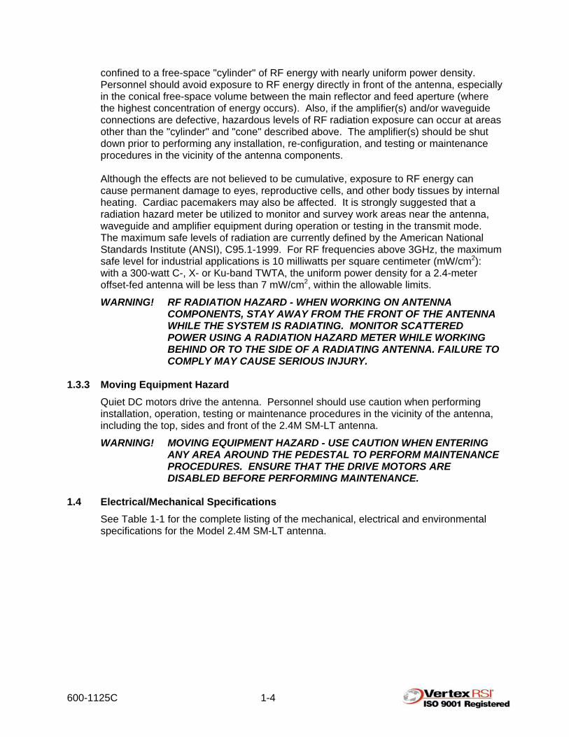
confined to a free-space "cylinder" of RF energy with nearly uniform power density. Personnel should avoid exposure to RF energy directly in front of the antenna, especially in the conical free-space volume between the main reflector and feed aperture (where the highest concentration of energy occurs). Also, if the amplifier(s) and/or waveguide connections are defective, hazardous levels of RF radiation exposure can occur at areas other than the "cylinder" and "cone" described above. The amplifier(s) should be shut down prior to performing any installation, re-configuration, and testing or maintenance procedures in the vicinity of the antenna components. Although the effects are not believed to be cumulative, exposure to RF energy can cause permanent damage to eyes, reproductive cells, and other body tissues by internal heating. Cardiac pacemakers may also be affected. It is strongly suggested that a radiation hazard meter be utilized to monitor and survey work areas near the antenna, waveguide and amplifier equipment during operation or testing in the transmit mode. The maximum safe levels of radiation are currently defined by the American National Standards Institute (ANSI), C95.1-1999. For RF frequencies above 3GHz, the maximum safe level for industrial applications is 10 milliwatts per square centimeter (mW/cm2): with a 300-watt C-, X- or Ku-band TWTA, the uniform power density for a 2.4-meter offset-fed antenna will be less than 7 mW/cm2, within the allowable limits.
WARNING! RF RADIATION HAZARD - WHEN WORKING ON ANTENNA COMPONENTS, STAY AWAY FROM THE FRONT OF THE ANTENNA WHILE THE SYSTEM IS RADIATING. MONITOR SCATTERED POWER USING A RADIATION HAZARD METER WHILE WORKING BEHIND OR TO THE SIDE OF A RADIATING ANTENNA. FAILURE TO COMPLY MAY CAUSE SERIOUS INJURY.
1.3.3 Moving Equipment Hazard
Quiet DC motors drive the antenna. Personnel should use caution when performing installation, operation, testing or maintenance procedures in the vicinity of the antenna, including the top, sides and front of the 2.4M SM-LT antenna.
WARNING! MOVING EQUIPMENT HAZARD - USE CAUTION WHEN ENTERING ANY AREA AROUND THE PEDESTAL TO PERFORM MAINTENANCE PROCEDURES. ENSURE THAT THE DRIVE MOTORS ARE DISABLED BEFORE PERFORMING MAINTENANCE.
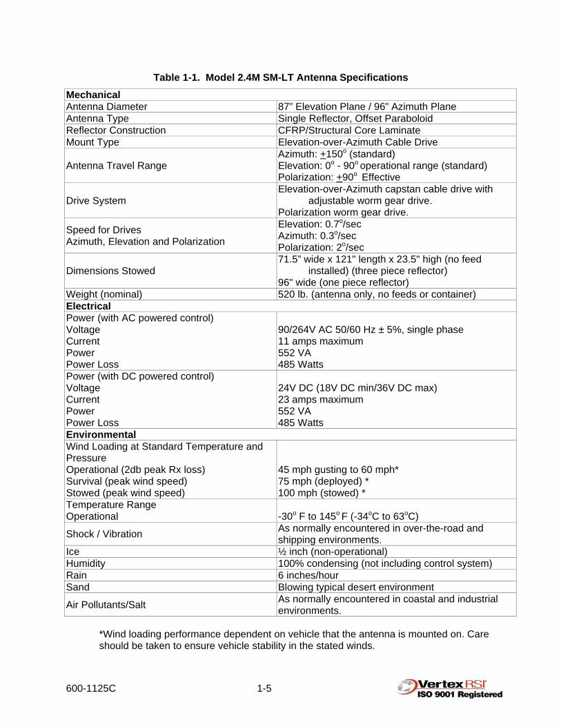
1.4 Electrical/Mechanical Specifications
See Table 1-1 for the complete listing of the mechanical, electrical and environmental specifications for the Model 2.4M SM-LT antenna.
600-1125C 1-5
Table 1-1. Model 2.4M SM-LT Antenna Specifications Mechanical Antenna Diameter 87” Elevation Plane / 96” Azimuth Plane Antenna Type Single Reflector, Offset Paraboloid Reflector Construction CFRP/Structural Core Laminate Mount Type Elevation-over-Azimuth Cable Drive
Antenna Travel Range Azimuth: +150o (standard) Elevation: 0o - 90o operational range (standard) Polarization: +90o Effective
Drive System Elevation-over-Azimuth capstan cable drive with
adjustable worm gear drive. Polarization worm gear drive.
Speed for Drives Azimuth, Elevation and Polarization
Elevation: 0.7o/sec Azimuth: 0.3o/sec Polarization: 2o/sec
Dimensions Stowed 71.5” wide x 121" length x 23.5" high (no feed
installed) (three piece reflector) 96" wide (one piece reflector)
Weight (nominal) 520 lb. (antenna only, no feeds or container) Electrical Power (with AC powered control) Voltage Current Power Power Loss
90/264V AC 50/60 Hz ± 5%, single phase 11 amps maximum 552 VA 485 Watts
Power (with DC powered control) Voltage Current Power Power Loss
24V DC (18V DC min/36V DC max) 23 amps maximum 552 VA 485 Watts
Environmental Wind Loading at Standard Temperature and Pressure Operational (2db peak Rx loss) Survival (peak wind speed) Stowed (peak wind speed)
45 mph gusting to 60 mph* 75 mph (deployed) * 100 mph (stowed) *
Temperature Range Operational
-30o F to 145o F (-34oC to 63oC)
Shock / Vibration As normally encountered in over-the-road and shipping environments.
Ice ½ inch (non-operational) Humidity 100% condensing (not including control system) Rain 6 inches/hour Sand Blowing typical desert environment
Air Pollutants/Salt As normally encountered in coastal and industrial environments.
*Wind loading performance dependent on vehicle that the antenna is mounted on. Care should be taken to ensure vehicle stability in the stated winds.
600-1125C 1-6
1.5 Transporting The Model 2.4M SM-LT Antenna System has been designed for simplified automatic deployment and stowing. (See the applicable Antenna Control System manual for additional information). The antenna is ready for transportation when in the stow position and a visual inspection indicates that the reflector is resting on its support bumper(s). Personnel must be familiar with the appearance and control indications for the stow configuration of the antenna as well as other vehicle systems to ensure safe transportation of the antenna.
1.6 Operation at Low Elevation Angles
Exercise caution when operating the motor drives at low elevation angles due to the proximity of the feed boom to the vehicle. Ensure that all potential obstacles (tools, access doors, lighting equipment and miscellaneous vehicle accessories) are clear of the feed arc.

600-1125C 2-1
2.0 EMERGENCY PROCEDURES
Note: Personnel should be familiar with their particular vehicle arrangement.
2.1 Hand Crank Procedure The azimuth, elevation and polarization axes may each be positioned manually in the event of an emergency. Turn off power to the antenna control system before manually positioning any of the axes.
Note: No harmful Electro Magnetic Fields (EMFs) are created by rotating the azimuth hand crank.
2.1.1 Azimuth
The azimuth hand crank input shaft is available near the rear of the antenna mount as shown in Figure 2-1. The shaft end is hexagonal 7/16" for standard socket operation. If so equipped, the VertexRSI 2.4M SM-LT incorporates an interlock switch that locks out antenna power during hand crank operation. Removal of the hand crank triggers this feature. The hand crank ratio is such that one turn of the input shaft generates 1.14 degrees of azimuth movement.
Figure 2-1. Hand Crank Input Shaft Locations
600-1125C 2-2
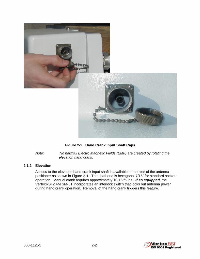
Figure 2-2. Hand Crank Input Shaft Caps
Note: No harmful Electro Magnetic Fields (EMF) are created by rotating the elevation hand crank.
2.1.2 Elevation
Access to the elevation hand crank input shaft is available at the rear of the antenna positioner as shown in Figure 2-1. The shaft end is hexagonal 7/16” for standard socket operation. Manual crank requires approximately 10-15 ft- lbs. If so equipped, the VertexRSI 2.4M SM-LT incorporates an interlock switch that locks out antenna power during hand crank operation. Removal of the hand crank triggers this feature.

600-1125C 2-3
Figure 2-3. Hand Crank Input Shafts

600-1125C 2-4
2.1.3 Polarization Manual adjustment of the polarization angle can be performed by de-meshing the drive pinion gear and simply rotating the feed. To de-mesh the drive pinion gear, loosen the two ¼-inch mounting bolts that retain the drive motor, then slide the motor away from the polarization axis as shown in Figure 2-4.
CAUTION! YOU MUST SUPPORT THE WEIGHT OF THE FEED AT ALL TIMES WHILE THE DRIVE PINION IS DE-MESHED.
Note: The orientation of the polarization drive system may vary depending upon your particular feed configuration.
Figure 2-4. Polarization Drive Motor
Note: Your feed may appear different than that shown here. These photos are shown for reference only.
Two ¼-inch

600-1125C 3-1
3.0 INSTALLATION 3.1 General Interface Requirements
The customer is responsible for the installation of antenna products purchased from General Dynamics SATCOM Technologies and for integrating the antenna system to the vehicle and/or vehicle systems. The vehicle interface drawing supplies the information necessary for this purpose.
The vehicle must provide a structural foundation for the antenna while allowing both internal and external clearance for the full range of motion. The rooftop may include a custom fairing to lower wind resistance in transport mode and to provide a smooth integration to the roofline for aesthetic considerations. Electrical requirements include providing space and electrical power in the equipment rack for the applicable Antenna Control System (ACS) as well as routing of cables and rigid waveguide from the antenna base to the associated equipment (if required).
3.2 Shipping Configuration
The antenna will be shipped as a fully assembled unit.
3.2.1 Assembled Configuration The antenna is shipped in a single container in the stowed position. The antenna pedestal bearing is secured on a specially-designed shipping stand within the container. The unit may be lifted from the container using a hoist or sling assembly.
3.2.2 Preparation for Removal from Shipping Stand Refer to the following installation instructions for your particular application regarding lifting the antenna.
Note: Definition of CFE is Customer-Furnished Equipment.
Step 1. Remove the top, sides and any internal braces or strapping from the shipping container. Do not damage the antenna while disassembling the shipping container.
Step 2. If a hoist will be used to lift the antenna, secure the feed boom to the stowed antenna as shown in Figure 3-1.

600-1125C 3-2
Figure 3-1. Feed Boom Secured to Reflector
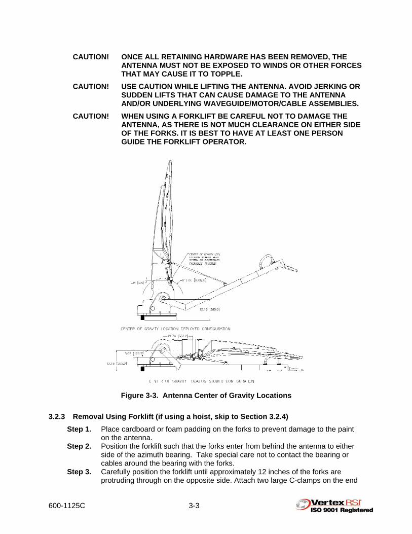
Step 3. Remove lag bolts (4 places). See Figure 3-2 for lag bolt locations. Doing so will allow the antenna to be lifted from the shipping skid. (If using a forklift, remove lag bolts only after raising antenna in elevation to achieve a “balance point” as shown in Figure 3-3.)
Figure 3-2. Lag Bolt Location
600-1125C 3-3
CAUTION! ONCE ALL RETAINING HARDWARE HAS BEEN REMOVED, THE ANTENNA MUST NOT BE EXPOSED TO WINDS OR OTHER FORCES THAT MAY CAUSE IT TO TOPPLE.
CAUTION! USE CAUTION WHILE LIFTING THE ANTENNA. AVOID JERKING OR SUDDEN LIFTS THAT CAN CAUSE DAMAGE TO THE ANTENNA AND/OR UNDERLYING WAVEGUIDE/MOTOR/CABLE ASSEMBLIES.
CAUTION! WHEN USING A FORKLIFT BE CAREFUL NOT TO DAMAGE THE ANTENNA, AS THERE IS NOT MUCH CLEARANCE ON EITHER SIDE OF THE FORKS. IT IS BEST TO HAVE AT LEAST ONE PERSON GUIDE THE FORKLIFT OPERATOR.
Figure 3-3. Antenna Center of Gravity Locations
3.2.3 Removal Using Forklift (if using a hoist, skip to Section 3.2.4)
Step 1. Place cardboard or foam padding on the forks to prevent damage to the paint on the antenna.
Step 2. Position the forklift such that the forks enter from behind the antenna to either side of the azimuth bearing. Take special care not to contact the bearing or cables around the bearing with the forks.
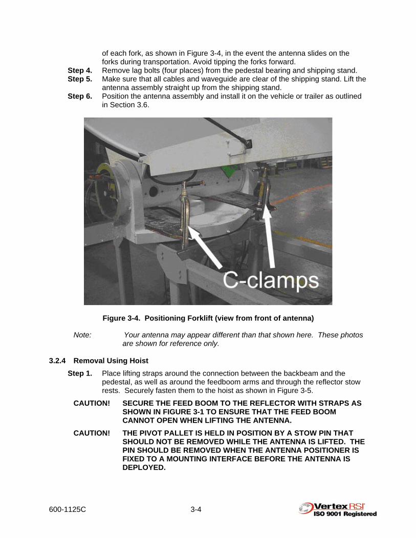
Step 3. Carefully position the forklift until approximately 12 inches of the forks are protruding through on the opposite side. Attach two large C-clamps on the end
600-1125C 3-4
of each fork, as shown in Figure 3-4, in the event the antenna slides on the forks during transportation. Avoid tipping the forks forward.
Step 4. Remove lag bolts (four places) from the pedestal bearing and shipping stand. Step 5. Make sure that all cables and waveguide are clear of the shipping stand. Lift the
antenna assembly straight up from the shipping stand. Step 6. Position the antenna assembly and install it on the vehicle or trailer as outlined
in Section 3.6.
Figure 3-4. Positioning Forklift (view from front of antenna)
Note: Your antenna may appear different than that shown here. These photos are shown for reference only.
3.2.4 Removal Using Hoist
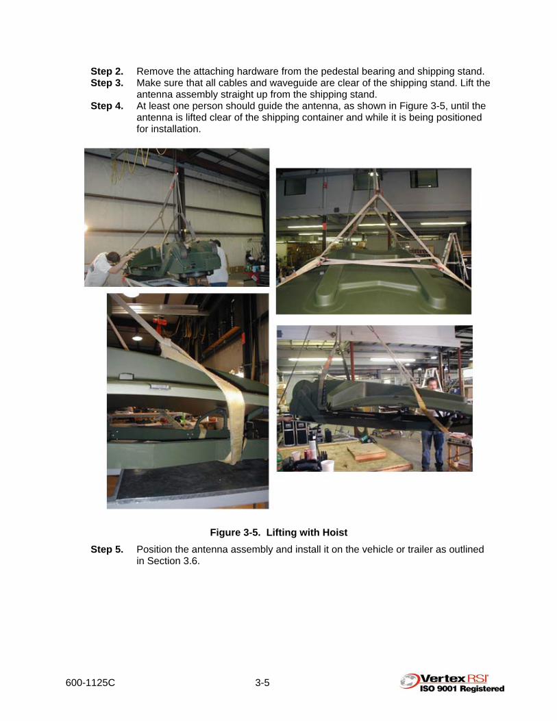
Step 1. Place lifting straps around the connection between the backbeam and the pedestal, as well as around the feedboom arms and through the reflector stow rests. Securely fasten them to the hoist as shown in Figure 3-5.
CAUTION! SECURE THE FEED BOOM TO THE REFLECTOR WITH STRAPS AS SHOWN IN FIGURE 3-1 TO ENSURE THAT THE FEED BOOM CANNOT OPEN WHEN LIFTING THE ANTENNA.
CAUTION! THE PIVOT PALLET IS HELD IN POSITION BY A STOW PIN THAT SHOULD NOT BE REMOVED WHILE THE ANTENNA IS LIFTED. THE PIN SHOULD BE REMOVED WHEN THE ANTENNA POSITIONER IS FIXED TO A MOUNTING INTERFACE BEFORE THE ANTENNA IS DEPLOYED.
600-1125C 3-5
Step 2. Remove the attaching hardware from the pedestal bearing and shipping stand. Step 3. Make sure that all cables and waveguide are clear of the shipping stand. Lift the
antenna assembly straight up from the shipping stand. Step 4. At least one person should guide the antenna, as shown in Figure 3-5, until the
antenna is lifted clear of the shipping container and while it is being positioned for installation.
Figure 3-5. Lifting with Hoist Step 5. Position the antenna assembly and install it on the vehicle or trailer as outlined
in Section 3.6.
600-1125C 3-6
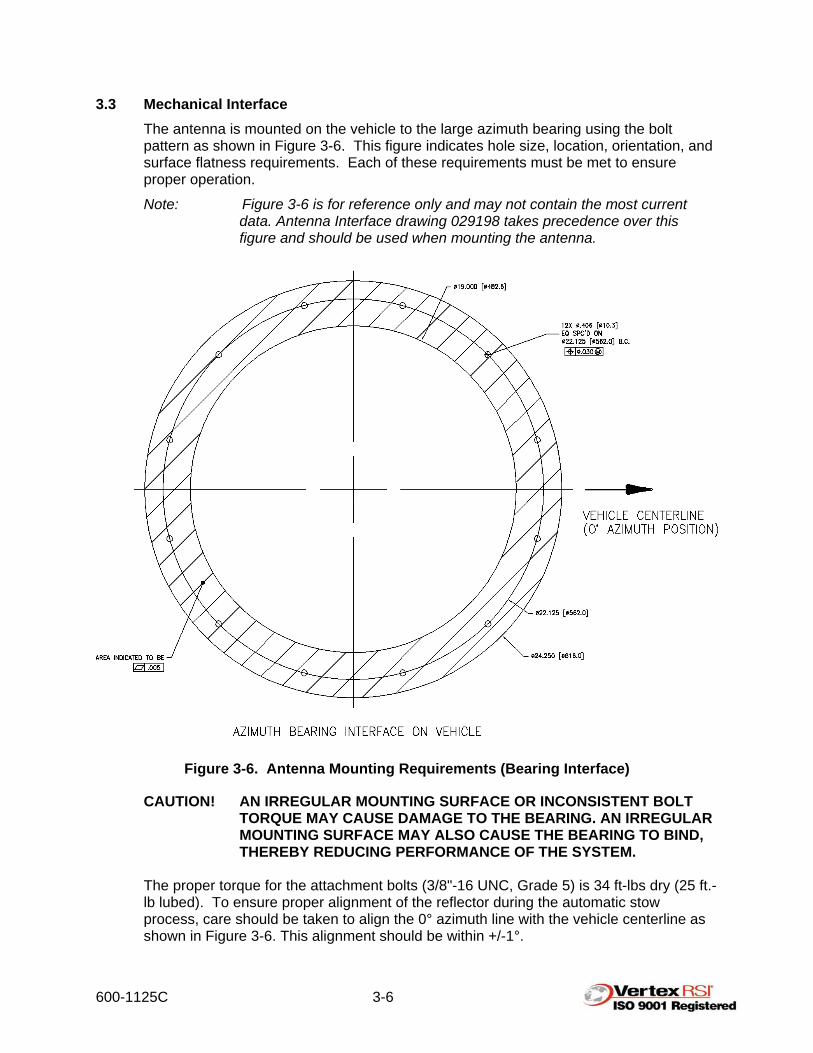
3.3 Mechanical Interface The antenna is mounted on the vehicle to the large azimuth bearing using the bolt pattern as shown in Figure 3-6. This figure indicates hole size, location, orientation, and surface flatness requirements. Each of these requirements must be met to ensure proper operation.
Note: Figure 3-6 is for reference only and may not contain the most current data. Antenna Interface drawing 029198 takes precedence over this figure and should be used when mounting the antenna.
Figure 3-6. Antenna Mounting Requirements (Bearing Interface)
CAUTION! AN IRREGULAR MOUNTING SURFACE OR INCONSISTENT BOLT TORQUE MAY CAUSE DAMAGE TO THE BEARING. AN IRREGULAR MOUNTING SURFACE MAY ALSO CAUSE THE BEARING TO BIND, THEREBY REDUCING PERFORMANCE OF THE SYSTEM.
The proper torque for the attachment bolts (3/8"-16 UNC, Grade 5) is 34 ft-lbs dry (25 ft.-lb lubed). To ensure proper alignment of the reflector during the automatic stow process, care should be taken to align the 0° azimuth line with the vehicle centerline as shown in Figure 3-6. This alignment should be within +/-1°.
600-1125C 3-7
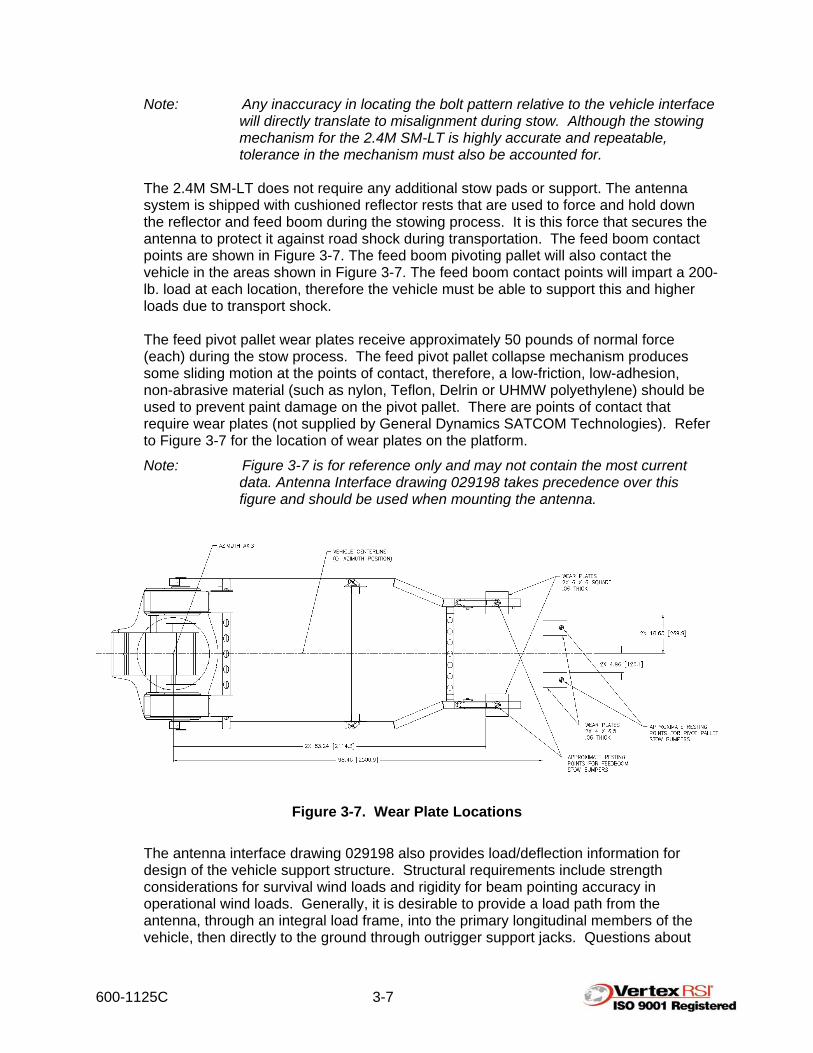
Note: Any inaccuracy in locating the bolt pattern relative to the vehicle interface will directly translate to misalignment during stow. Although the stowing mechanism for the 2.4M SM-LT is highly accurate and repeatable, tolerance in the mechanism must also be accounted for.
The 2.4M SM-LT does not require any additional stow pads or support. The antenna system is shipped with cushioned reflector rests that are used to force and hold down the reflector and feed boom during the stowing process. It is this force that secures the antenna to protect it against road shock during transportation. The feed boom contact points are shown in Figure 3-7. The feed boom pivoting pallet will also contact the vehicle in the areas shown in Figure 3-7. The feed boom contact points will impart a 200-lb. load at each location, therefore the vehicle must be able to support this and higher loads due to transport shock. The feed pivot pallet wear plates receive approximately 50 pounds of normal force (each) during the stow process. The feed pivot pallet collapse mechanism produces some sliding motion at the points of contact, therefore, a low-friction, low-adhesion, non-abrasive material (such as nylon, Teflon, Delrin or UHMW polyethylene) should be used to prevent paint damage on the pivot pallet. There are points of contact that require wear plates (not supplied by General Dynamics SATCOM Technologies). Refer to Figure 3-7 for the location of wear plates on the platform.
Note: Figure 3-7 is for reference only and may not contain the most current data. Antenna Interface drawing 029198 takes precedence over this figure and should be used when mounting the antenna.
Figure 3-7. Wear Plate Locations The antenna interface drawing 029198 also provides load/deflection information for design of the vehicle support structure. Structural requirements include strength considerations for survival wind loads and rigidity for beam pointing accuracy in operational wind loads. Generally, it is desirable to provide a load path from the antenna, through an integral load frame, into the primary longitudinal members of the vehicle, then directly to the ground through outrigger support jacks. Questions about

600-1125C 3-8
mechanical integration of the antenna to the vehicle structure may be directed to the engineering department of General Dynamics SATCOM Technologies.
3.4 RF Interface
Optional waveguide kits are available upon request. Consult with the General Dynamics SATCOM Technologies Sales or Engineering staff for custom solutions for LNA and HPA mounting and cooling. See Figure 3-8 for available space on the antenna structure for associated electronics.
Figure 3-8. Equipment Bays
Note: Due to the curvature of the reflector, available mounting area on feed boom structure under the reflector is variable. Amount of available area depends on the size and shape of the electronic equipment. Consult with General Dynamics SATCOM Technologies Engineering for further information.
Note: Feedboom mounted electronics equipment should not exceed 150 pounds.
3.5 Controls
The pedestal is pre-wired for direct connection to the Antenna Control System (ACS). The umbilical cables are precut and terminated to a length of 25 feet (nominally) from the base of the antenna pedestal.

600-1125C 3-9
Figure 3-9. Umbilical Cables
Note: Due to the fact that a variety of different control systems may be used, reference appropriate antenna interconnect diagram for control system wiring configuration.
3.6 Installation Procedure
Note: The opening in the trailer/vehicle must be Ø19" in diameter as shown in Figure 3-6 or vehicle interface drawing 029198.
Step 1. Apply a bead of silicone around the opening approximately 2-1/2" from the edge
of the opening as shown in Figure 3-10. The bead should be located just outside the antenna-mounting bolt holes.
Figure 3-10. Silicone Bead Step 2. Carefully lower the antenna over the opening making sure to route all cables
through the opening as shown in Figures 3-11 and 3-12. Do not to disturb the silicone bead.

600-1125C 3-10
Important: At least one person should steady the antenna by supporting the feed boom as shown in Figure 3-13.
Step 3. Carefully guide the antenna as it is lowered into the opening as shown in Figure
3-12. Use alignment pins or spare bolts to align the antenna bolt holes to the vehicle bolt holes as the antenna is lowered into position.
Figure 3-11. Cable Routing
Figure 3-12. Antenna Positioning
Note: Your antenna may appear different than that shown here. These pictures are shown for reference only.

600-1125C 3-11
Figure 3-13. Antenna Stabilization
Note: Your antenna may appear different than that shown here. These pictures are shown for reference only.
Figure 3-14. Bolt Installation Step 4. All 12 bolt holes (3/8-16 UNC tapped holes in bearing interface) should be
accessible from below the antenna interface. The antenna does not require rotation to gain bolt access if properly aligned with vehicle interface.

600-1125C 3-12
Step 5. Tighten all 12 (3/8"-16 UNC grade 5) bolts to 34 ft-lbs (dry) each (25 ft-lbs
lubed). Step 6. If using a hoist, remove it and the lifting strap from the antenna. Step 7. Attach the customer-furnished waveguide and RF subsystem components (as
required) on the antenna.
Note: When RF equipment is to be mounted inside the vehicle, General Dynamics SATCOM Technologies recommends incorporating rotary joints on both the elevation and azimuth axes. General Dynamics SATCOM Technologies can provide a pre-engineered solution; for more information, contact the General Dynamics SATCOM Technologies Sales department or Engineering department.
Step 8. Install the customer-furnished RF subsystem components on the feed boom as
required. Step 9. Install the ACS components where desired. Connect the antenna interface
cables to the ACS components as described in the ACS manual (standard cables are 25' long from the base of the pedestal).
Step 10. See the ACS manual for control system wiring. Step 11. Install the feed boom wear plates as shown in Figure 3-9.

600-1125C 4-1
4.0 AZIMUTH POSITION SYSTEM 4.1 Azimuth Bearing
The azimuth bearing is a precision ground Slim Line ball bearing with a dynamic and static moment capacity of nearly four times the worst-case wind load specification. It is press / shrink fit into a special aluminum bearing ring. The bearing is sealed against contaminants with Teflon O-rings. The bearing is packed with Mobil 1 synthetic grease at assembly.
Because of the excess capacity, low rpm, and low number of cycles compared to the bearing’s design life, no appreciable wear is expected. No maintenance should be required over the life of the positioner.
4.2 Azimuth Gear Box
The azimuth gearbox is a patented low backlash worm gear box. The worm gear drive isolates any backlash in the motor drive from the system. Also, since it is a 40:1 ratio it will not backdrive, thereby eliminating any need for a brake on the drive train (see Figure 4.1).
Figure 4-1. Azimuth Motor and Gearbox

600-1125C 4-2
The motor drives the input worm via a quill / female hole and square key. The worm shaft is extended with a hex shape for the handcrank. The azimuth capstan is secured to the output shaft with a square key and zero backlash hub. The low backlash is achieved with a variable pitch worm. The width of the worm tooth slowly increases along the worm. Since only one small portion of the worm tooth is meshing with the worm gear, by moving the worm axially, you can vary which section / width of the worm tooth is being used to drive the worm gear. Therefore the backlash can always be minimized to 1-3-arc minutes (see Figure 4.2). The gearbox contains synthetic oil filled half way to the level plugs. Because of the design capacity of the gearbox, low rpm and comparative limited cycles experienced by an SNG system, no appreciable wear is expected. If azimuth backlash of the positioner ever exceeds 0.020° on axis, it may be brought back to the 0.005° factory setting by adjusting backlash in the gearbox (see Figure 4.2).
Figure 4-2. Internal Components of Gear Reducer 4.3 Azimuth Motor
The azimuth drive motor is a flat armature, servo quality, DC motor with integral 150:1 spur gear train. The motor armature rotates at up to 4500 rpm causing a high frequency noise that will vary depending on the loading condition of the motor (See Figure 4.1).
The maximum output speed is 40 rpm. The output shaft is “D” shaped with a special adapter with a slot for a square key. Since the low backlash worm gear drive isolates the backlash from the motor, any backlash between the shaft adapter, square key or motor gear train will not be seen by the reflector boresight.

600-1125C 4-3
No maintenance or appreciable wear of the azimuth motor is expected. 4.4 Azimuth Cable Drive
The azimuth drive produces a near-zero backlash, high stiffness, low-wear, drive system which requires no lubrication. Because of this, the system is highly reliable. The system consists of four 1/8” diameter, 9 x 17 stainless steel aircraft control cables reverse wrapped twice around the grooved capstan with solid connections on one end and high force, belleville springs on the other end. One cable has the capacity to withstand the 60-mph wind load. The additional cables are used to provided increased stiffness and drive redundancy. If a cable becomes damaged during usage, merely cut off the cable and continue to use the positioner. The cable can be replaced whenever time permits at a typical maintenance facility.
The cables are sized to last the life of the positioner. No replacement from wear is expected. The spring package at one end will automatically compensate for any elongation of the cable (see Figure 4.3).
Figure 4-3. Azimuth Bearing Cable Connections
Belleville W h

600-1125C 4-4
Since all systems seek the condition of lowest potential energy, the cables after an adequate time for break in will eventually stop stretching. At installation the belleville springs are collapsed until no “air” is seen between the springs. You should check this condition yearly to account for the slow settling of the cable strands. Use a 1/4 open wrench or pliers to hold the stud and 7/16 box end wrench to tighten nut. Be sure not to over tighten the cables, but the belleville springs should almost be fully collapsed (see Figure 4.3).

600-1125C 5-1
5.0 ELEVATION POSITION SYSTEM The elevation pivot assembly consists of two elevation drum assemblies pivoting between two clevis blades that house the precision aircraft torque tube bearings. These bearings are precision ground with lifetime seals. They are permanently lubricated with synthetic grease. No appreciable wear is expected.
5.1 Elevation Gear Box The elevation gearbox is a patented low backlash worm gear box. The worm gear drive isolates backlash in the motor drive from the system. Also, since it is a 40:1 ratio it will not backdrive, thereby eliminating any need for a brake on the drive train (see Figure 5.1).
Figure 5-1. Top View of Positioner
600-1125C 5-2
The motor drives the input worm via a quill / female hole and square key. The worm shaft is extended with a hex shape for the hand crank. The dual elevation drive shafts are driven with a square key. Zero backlash hubs are used to eliminate any backlash between keyed shafts. They are factory tightened and should never be tightened again. Over-tightening can bind gearbox bearings. The elevation capstan is secured to the dual output shafts with four cap screws. These screws are the “safety link” and will shear under excessive loading conditions to protect the elevation drive system if the reflector is not stowed and hits an obstacle while the vehicle is in motion. The low backlash is achieved with a variable pitch worm. The width of the worm tooth slowly increases along the worm. Since only one small portion of the worm tooth is meshing with the worm gear moving the worm axially allows one to vary which section / width of the worm tooth is being used to drive the worm gear. Therefore the backlash can always be minimized to 1 – 3 arc minutes (see Figure 4.2). The gear box contains synthetic oil filled half way to the level plugs. Due to the design capacity of the gear box, low rpm and comparative limited cycles experienced by an SNG system, no appreciable wear is expected.
5.2 Elevation Motor
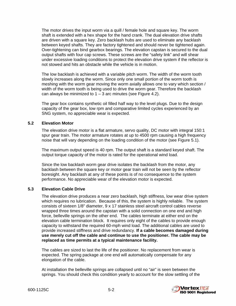
The elevation drive motor is a flat armature, servo quality, DC motor with integral 150:1 spur gear train. The motor armature rotates at up to 4500 rpm causing a high frequency noise that will vary depending on the loading condition of the motor (see Figure 5.1).
The maximum output speed is 40 rpm. The output shaft is a standard keyed shaft. The output torque capacity of the motor is rated for the operational wind load. Since the low backlash worm gear drive isolates the backlash from the motor, any backlash between the square key or motor gear train will not be seen by the reflector boresight. Any backlash at any of these points is of no consequence to the system performance. No appreciable wear of the elevation motor is expected.
5.3 Elevation Cable Drive
The elevation drive produces a near zero backlash, high stiffness, low wear drive system which requires no lubrication. Because of this, the system is highly reliable. The system consists of sixteen 1/8” diameter, 9 x 17 stainless steel aircraft control cables reverse wrapped three times around the capstan with a solid connection on one end and high force, belleville springs on the other end. The cables terminate at either end on the elevation cable termination block. It requires only eight of the cables to provide enough capacity to withstand the required 60-mph wind load. The additional cables are used to provide increased stiffness and drive redundancy. If a cable becomes damaged during use merely cut off the cable and continue to use the positioner. The cable may be replaced as time permits at a typical maintenance facility.
The cables are sized to last the life of the positioner. No replacement from wear is expected. The spring package at one end will automatically compensate for any elongation of the cable. At installation the belleville springs are collapsed until no “air” is seen between the springs. You should check this condition yearly to account for the slow settling of the
600-1125C 5-3
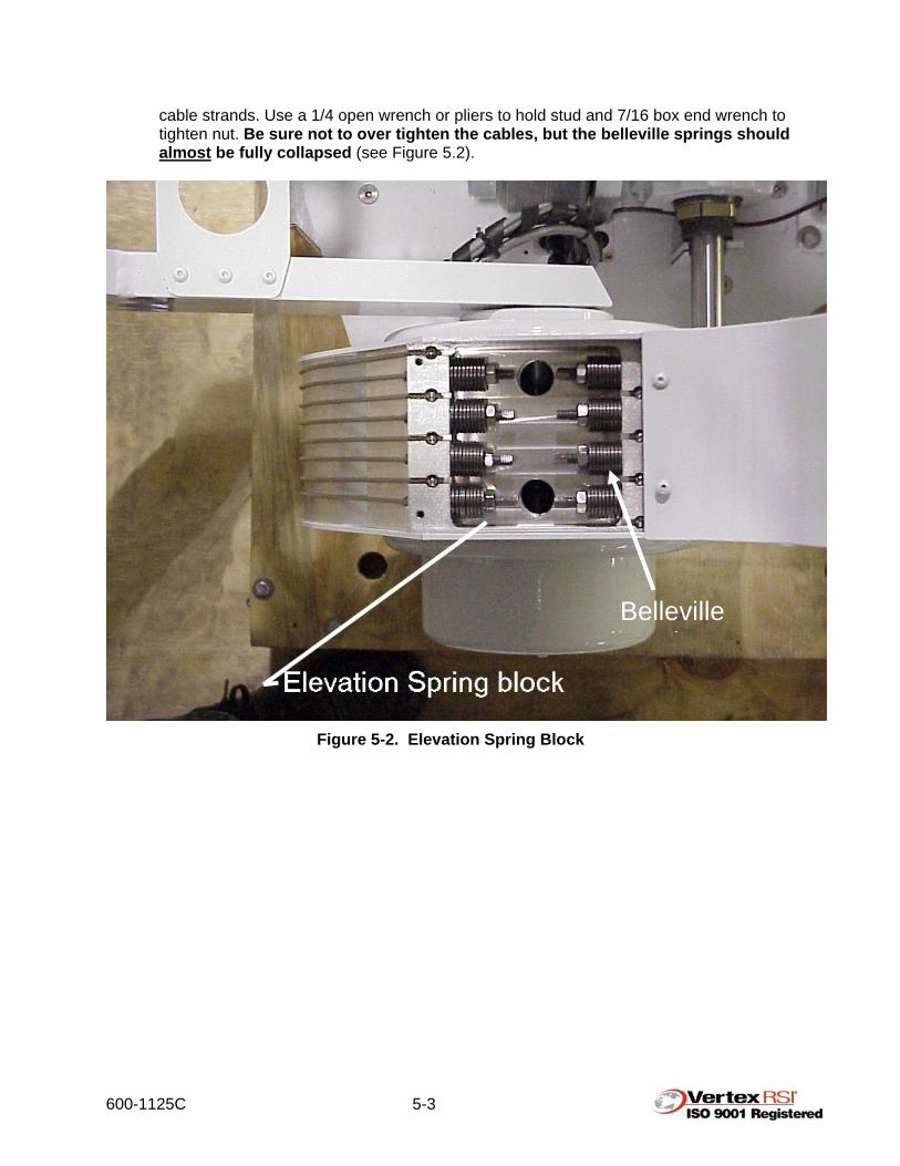
cable strands. Use a 1/4 open wrench or pliers to hold stud and 7/16 box end wrench to tighten nut. Be sure not to over tighten the cables, but the belleville springs should almost be fully collapsed (see Figure 5.2).
Figure 5-2. Elevation Spring Block
Belleville W h

600-1125C 6-1
6.0 MAINTENANCE The intent of this section of the VertexRSI Model 2.4M SM-LT instruction manual is to provide information sufficient to conduct routine maintenance procedures on the antenna system. Section 6.1 covers preventative maintenance and its scheduling.
Note: Always inspect your antenna system prior to use for obvious signs of damage or wear. If possible, observe the antenna during stowing and/or deploying operations to ensure damage to the antenna and/or vehicle does not occur!
6.1 Preventative Maintenance
This section details the routine maintenance requirements for the VertexRSI Model 2.4M SM-LT antenna. The procedures will consist primarily of periodic physical inspection of parts and preventative maintenance techniques.
6.1.1 Physical Inspection and Service Physically inspect the antenna parts and components as outlined in Table 6-1 and Figure 6-1. Table 6-1 lists servicing requirements, scheduling, and consumables needed.
Table 6-1. Maintenance Schedule
Item Interval Activity Location
Elevation and Azimuth Axis Gearboxes 12 months Oil (MobilGear #629) A
Elevation Hand Crank Operation 12 months Inspect B
Azimuth Bearing Operation 12 months Inspect C
Azimuth Hand Crank Operation 12 months Inspect D
All Visible Hardware 6 months Inspect Antenna
Cable Harness 6 months Inspect Antenna
Flexible Waveguide 6 months Inspect G
Polarization Drive Gearing 12 months Grease (Monolec #4701) H
Feed Window 6 months Inspect I
Feed Boom/Pivoting Pallet Struts 6 months Inspect J
Ferrous Metal Surfaces 6 months Inspect/Re-coat Antenna
Positioner (A)
Paint 6 months Inspect/touch up Antenna
600-1125C 6-2
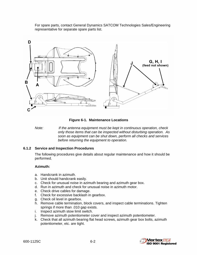
For spare parts, contact General Dynamics SATCOM Technologies Sales/Engineering representative for separate spare parts list.
Figure 6-1. Maintenance Locations
Note: If the antenna equipment must be kept in continuous operation, check only those items that can be inspected without disturbing operation. As soon as equipment can be shut down, perform all checks and services before returning the equipment to operation.
6.1.2 Service and Inspection Procedures
The following procedures give details about regular maintenance and how it should be performed. Azimuth: a. Handcrank in azimuth. b. Unit should handcrank easily. c. Check for unusual noise in azimuth bearing and azimuth gear box. d. Run in azimuth and check for unusual noise in azimuth motor. e. Check drive cables for damage. f. Check for excessive backlash in gearbox. g. Check oil level in gearbox. h. Remove cable termination, block covers, and inspect cable terminations. Tighten
springs if more than .010 gap exists. i. Inspect azimuth stow limit switch. j. Remove azimuth potentiometer cover and inspect azimuth potentiometer. k. Check that all azimuth bearing flat head screws, azimuth gear box bolts, azimuth
potentiometer, etc. are tight.

600-1125C 6-3
Elevation: a. Handcrank in elevation. b. Unit should handcrank with approximately 10-15 ft-lbs. torque. c. Check for unusual noise in elevation pivot bearings and elevation gearbox. d. Run in elevation and check for unusual noise in elevation motor. e. Run to up limit. f. Check tracking of elevation drive cables. g. Check drive cables for damage. h. Check for excessive backlash in gear box. i. Check that anti-backlash hubs are tight. j. Check oil level in gearbox. k. Remove cable termination block covers and inspect cable terminations. Tighten
springs if more than .010 gap between sets of springs exists.
Figure 6-2. Maintenance Locations (Gearboxes)
600-1125C 6-4
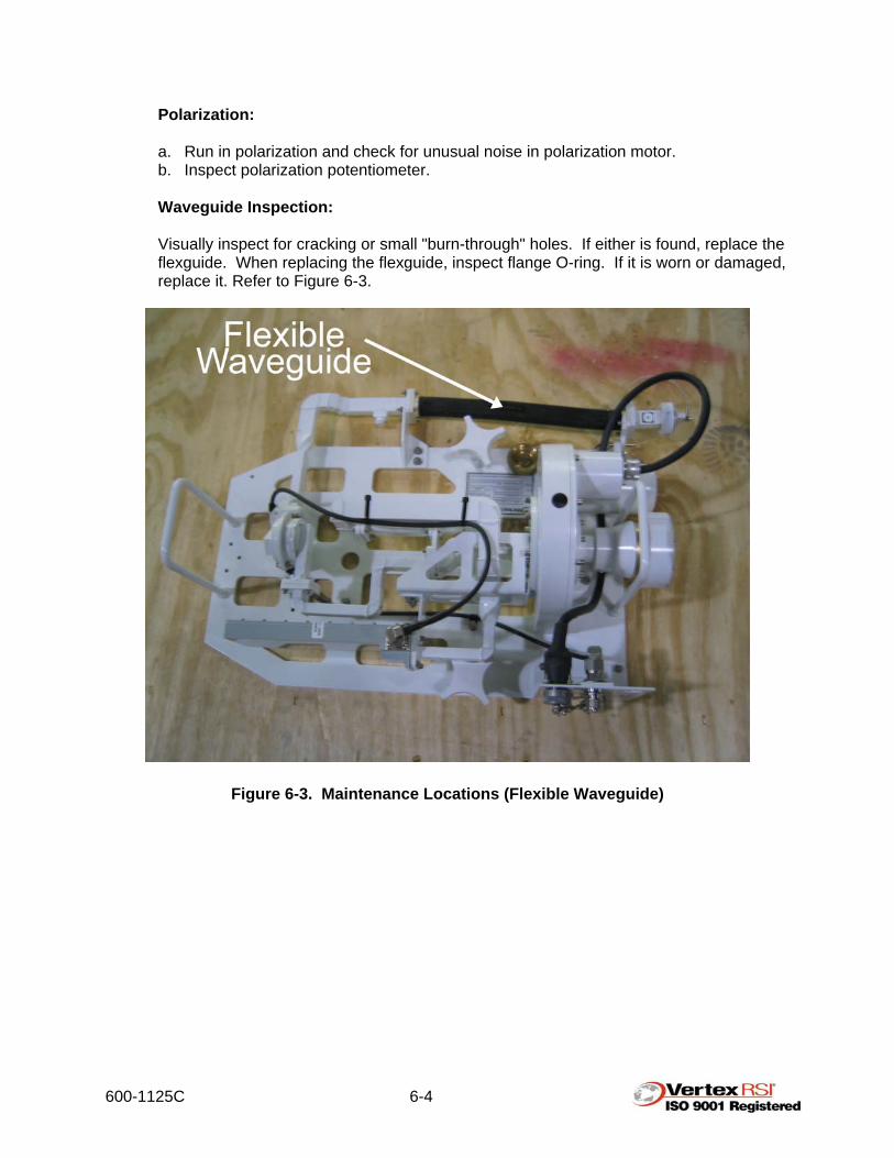
Polarization: a. Run in polarization and check for unusual noise in polarization motor. b. Inspect polarization potentiometer. Waveguide Inspection: Visually inspect for cracking or small "burn-through" holes. If either is found, replace the flexguide. When replacing the flexguide, inspect flange O-ring. If it is worn or damaged, replace it. Refer to Figure 6-3.
Figure 6-3. Maintenance Locations (Flexible Waveguide)

600-1125C 6-5
Feed Window: Inspect the feed window (Teflon) for cracks or poor sealing around the edge. If faulty, replace per General Dynamics SATCOM Technologies specification 400-2453 (X-band, Appendix C) or 400-2467 (C-band, Appendix D). Either of these procedures will also apply to Ka- and Ku-band feed window replacement. Refer to Figure 6-4.
Figure 6-4. Feed Window
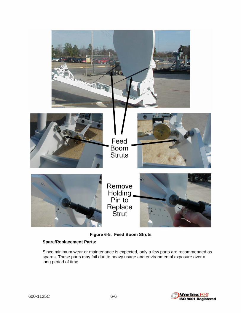
Feed Boom Struts: Examine the struts for play or misalignment. Visually inspect for corrosion. If any of these conditions exist, replace the struts. Refer to Figure 6-5. Ferrous Metal Inspection: Examine azimuth and elevation gearboxes for apparent corrosion and/or rust. If corrosion is found, the surface should be treated according to General Dynamics SATCOM Technologies procedure 965-0006 (see Appendix A). If no corrosion is found, General Dynamics SATCOM Technologies recommends that a corrosion resistant coating be applied to the surface to prevent future oxidation. If the antenna is located in a particularly harsh environment, inspection times should be more frequent than every six months.
600-1125C 6-6
Figure 6-5. Feed Boom Struts
Spare/Replacement Parts: Since minimum wear or maintenance is expected, only a few parts are recommended as spares. These parts may fail due to heavy usage and environmental exposure over a long period of time.

600-1125C 6-7
6.2 General Maintenance Procedures The purpose of this section is to provide maintenance procedures and equipment that can be applied to most or all subassemblies on the 2.4M SM-LT.
Table 6-2. Torque Values
Fastener Torque Chart (ASTM A325)
Screw Size Torque (lb/ft) (dry)
1/4 - 20 10
5/16 – 18 20
3/8 – 16 34
1/2 - 13 84
5/8 – 11 165
3/4 - 10 292
1 - 8 676
6.2.1 Paint and Corrosion Repair
Refinishing may be required due to damage caused during assembly, disassembly, transportation, or by adverse environmental conditions. Painted Surfaces: To touch up painted aluminum surfaces, thoroughly clean the area to be refinished. If corrosion is present, prepare the surface prior to cleaning by using a wire brush and/or by sanding it with emery cloth or fine sandpaper. After preparing the surface, clean it using a solvent (such as isopropyl alcohol) that does not leave an oily residue. Let the surface dry thoroughly. After the affected area has been properly prepared, apply the appropriate primer and paint using a small, fine brush for small chips and scrapes or an atomizer spray gun for structures and main components.

600-1125C 6-8
Paint Specification: Contact General Dynamics SATCOM Technologies engineering department for particular paint and/or primer specifications for your particular antenna. When calling, have your serial number, manufacturer code and model number available to expedite your call. There will be a serial number plate on the right-hand side (facing the back of the reflector) of the antenna backbeam.
Figure 6-6. Serial Number Plate Location Corrosion: Any surface that appears to have corrosion should be treated and cleaned before being painted according to the proper procedure (965-0006). Any hardware that exhibits signs of corrosion should be replaced. Cleaning: Clean exposed members with a detergent and water solution to remove dirt, dust, and salt deposits. Rinse with clean water and let dry. Do not spray water directly on electrical components. Repair of Composite Components: Repairing Holes
Step 1. Locate hole location on the front and rear sides of the reflector. Step 2. Grind out holes slightly larger than original hole. Step 3. Carve out inner foam slightly larger than the hole. Step 4. Use clear tape on front surface to cover the hole. Step 5. Fill hole, from the back, with syntactic filler (refer to manufacturer’s
recommended mixing instructions on the container).

600-1125C 6-9
Step 6. Allow patch to dry for twenty-four hours. Step 7. Sand filler on front side with 180-grit sandpaper. Step 8. Sand filler on rear side with 80-grit paper. Step 9. Paint over repaired area.
Repairing Cracks
Step 1. Use clear tape on front surface to cover the crack. Step 2. Fill crack, from the back, with syntactic filler (refer to manufacturer’s
recommended mixing instructions on the container). Step 3. Allow patch to dry for twenty-four hours. Step 4. Sand filler on front side with 180-grit sandpaper. Step 5. Sand filler on rear side with 80-grit sandpaper. Step 6. Paint over repaired area.
CAUTION! A POTENTIAL ELECTRICAL HAZARD EXISTS WHEN WATER AND ELECTRICAL COMPONENTS COME INTO CONTACT WITH EACH OTHER.
6.2.2 Wiring Repair
When repairing wire, note the wiring color codes. Since the 2.4M SM-LT has many moving parts, lengths of wires and potential abrasion wear must be considered during any wiring repair.
Important: Prior to removing or replacing any cables, note proper routing through the pedestal and/or feed boom. Cable abrasion may occur if the existing service loops and strain reliefs are not utilized.
6.3 Control System Information
See the ACS O&M manual for more details.
Note: Some control systems utilize a mechanical switch for stowing the antenna. If this type of control system is being used, use procedure 965-0008 in Appendix D to ensure that the stow limit is set correctly.
Motor Drive and Limit Switches. All motors are DC, 0 – 17-volt variable speed. Reversing the polarity can reverse their direction. Axis Current in Amps (typical) Azimuth 1.5 Elevation – up 4 Elevation - down 3 Polarization 0.34 The travel limit circuits utilize 24V DC. Both normally open (NO) and normally closed (NC) logic circuits are available. Refer to the ACS O&M manual.
Note: The limit switches are backed up by a current limiting feature in the ACS. The system will contact a hard stop, but the ACS will provide a current that will limit the amount of torque supplied to the pertinent axis.
600-1125C 7-1
7.0 GENERAL OPERATION Control of the VertexRSI Model 2.4M SM-LT antenna system is conducted from the Antenna Control System (ACS). The ACS provides antenna movement control (motor drives) and feed polarization control independently. The controller does not provide waveguide switching. The movement controls are, in turn, either automatic or manual. Refer to the ACS operation and maintenance manual for specific operating instructions.
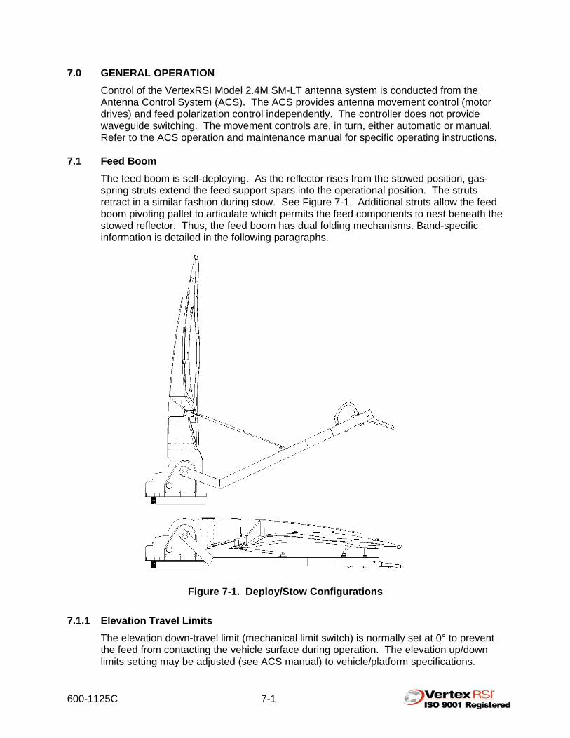
7.1 Feed Boom The feed boom is self-deploying. As the reflector rises from the stowed position, gas-spring struts extend the feed support spars into the operational position. The struts retract in a similar fashion during stow. See Figure 7-1. Additional struts allow the feed boom pivoting pallet to articulate which permits the feed components to nest beneath the stowed reflector. Thus, the feed boom has dual folding mechanisms. Band-specific information is detailed in the following paragraphs.
Figure 7-1. Deploy/Stow Configurations
7.1.1 Elevation Travel Limits
The elevation down-travel limit (mechanical limit switch) is normally set at 0° to prevent the feed from contacting the vehicle surface during operation. The elevation up/down limits setting may be adjusted (see ACS manual) to vehicle/platform specifications.
600-1125C 7-2
Manual override of controller limits may be performed with caution. The elevation up-travel limit (mechanical limit switch) is normally set at 90°.
7.1.2 Azimuth Travel Limits The azimuth travel limits (mechanical limit switches) are typically set at +/- 150°. The azimuth CW/CCW limits may be set at different angles if required. Please contact General Dynamics SATCOM Technologies Sales/Engineering representative for details.
7.1.3 General Feed Information Feeds come in a variety of configurations. This manual covers several varieties, but may not cover specific aspects of every feed system. Example: If you order a single Ku-band feed, it may or may not have any additional waveguide. You would refer to the Ku-band feed installation section, but ignore comments regarding additional waveguide that is intended for multi-band units.
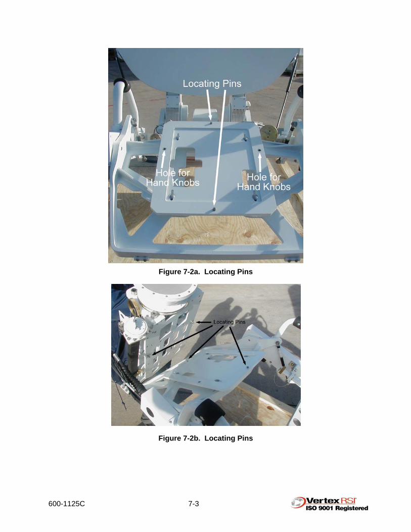
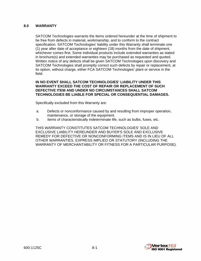
7.2 Multi-Band Feed Systems The antenna is currently capable of operating in four frequencies; Ku-band, Ka-band, X-band and C-band, depending on the particular feed that is installed. The following information is true for all feeds: • Removal/replacement of the feed requires disconnecting the waveguide and
electrical cables. The waveguide is equipped with quick-disconnect flanges that separate simply by unscrewing the knurled collar.
• The coaxial cables separate by push-pull connectors. • The multi-conductor cables separate by quarter-turn, military-style connectors. • The feed is positioned on the feed boom utilizing two locating pins as shown in
Figure 7-2.
Note: The locating pins are difficult to see once the feed has been placed over them. Care should be taken to locate one pin with the feed pallet while gently moving the feed around to find the other pin. Refer to Figure 7-2.
• The feed is installed using two captive hand knobs on each feed pallet.
600-1125C 7-3
Figure 7-2a. Locating Pins
Figure 7-2b. Locating Pins

600-1125C 7-4
7.2.1 Installation and Storage The feed must be rotated to the counterclockwise limit polarization angle (both linear and circular modes) so that the receive electronics package clears the reflector surface during transportation in the stowed configuration.
CAUTION! THE FEED ATTACHMENT HAND KNOBS MUST BE ENGAGED PRIOR TO TRANSPORTATION.
CAUTION! WHEN LIFTING THE FEED DO NOT USE THE FEED HORN OR WAVEGUIDE AS A HANDLE OR DAMAGE MAY OCCUR.
Step 1. Lift the feed and carefully place it on the feed boom using the locating pins to
properly position the feed, as shown in Figure 7-2.
Note: The locating pins are difficult to see once the feed has been placed over them.
Step 2. Secure the feed to the feed boom using the two captive hand knobs, as shown
in Figure 7-3.
Note: There is an O-ring in the connector on the feed, shown in Figure 7-5. Always ensure that it is in place and in good condition before attaching the waveguide to the feed.
Figure 7-3. Feed Attachment to Pallet

600-1125C 7-5
Step 3. Prepare the feed for installation by removing the cap from the back of the feed and storing it in the parking bracket as shown in Figure 7-4.
Figure 7-4. Waveguide Cap

600-1125C 7-6
Step 4. Attach flexible waveguide as shown in Figure 7-5.
Figure 7-5. Attach Waveguide

600-1125C 7-7
Figure 7-6. Installed Waveguide Step 5. Remove the cap from the waveguide at the back of the feed boom and store it
on the parking bracket as shown in Figure 7-7.
Figure 7-7. Waveguide Cap Storage

600-1125C 7-8
Step 6. Free the flexible waveguide from the feed as shown in Figure 7-8.
Figure 7-8a. Waveguide Attachment
Step 7. Attach the flexible waveguide, as shown in Figure 7-8.
Figure 7-8b. Waveguide Attachment

600-1125C 7-9
Step 8. Remove the multi-conductor cable from its storage position in the feed boom, as shown in Figure 7-10. Remove the cap from the multi-conductor cable plug on the feed and install the multi-conductor cable as shown in Figure 7-11.
Figure 7-9. Storage Location of Multi-Conductor Cable

600-1125C 7-10
Figure 7-10. Multi-Conductor Cable Installation Step 9. Ensure that all other unused waveguide connections are terminated. Step 10. The antenna is ready to operate.

600-1125C 7-11
Figure 7-11. Operating Position
600-1125C 8-1
8.0 WARRANTY SATCOM Technologies warrants the items ordered hereunder at the time of shipment to be free from defects in material, workmanship, and to conform to the contract specification. SATCOM Technologies’ liability under this Warranty shall terminate one (1) year after date of acceptance or eighteen (18) months from the date of shipment, whichever comes first. Some individual products include extended warranties as stated in brochure(s) and extended warranties may be purchased as requested and quoted. Written notice of any defects shall be given SATCOM Technologies upon discovery and SATCOM Technologies shall promptly correct such defects by repair or replacement, at its option, without charge, either FCA SATCOM Technologies’ plant or service in the field. IN NO EVENT SHALL SATCOM TECHNOLOGIES’ LIABILITY UNDER THIS WARRANTY EXCEED THE COST OF REPAIR OR REPLACEMENT OF SUCH DEFECTIVE ITEM AND UNDER NO CIRCUMSTANCES SHALL SATCOM TECHNOLOGIES BE LIABLE FOR SPECIAL OR CONSEQUENTIAL DAMAGES. Specifically excluded from this Warranty are: a. Defects or nonconformance caused by and resulting from improper operation,
maintenance, or storage of the equipment. b. Items of characteristically indeterminate life, such as bulbs, fuses, etc. THIS WARRANTY CONSTITUTES SATCOM TECHNOLOGIES’ SOLE AND EXCLUSIVE LIABILITY HEREUNDER AND BUYER'S SOLE AND EXCLUSIVE REMEDY FOR DEFECTIVE OR NONCONFORMING ITEMS AND IS IN LIEU OF ALL OTHER WARRANTIES, EXPRESS IMPLIED OR STATUTORY (INCLUDING THE WARRANTY OF MERCHANTABILITY OR FITNESS FOR A PARTICULAR PURPOSE).

600-1125C A-1
APPENDIX A. 965-0006: PROCEDURE FOR THE PREPARATION OF NON-PAINTED FERROUS METAL SURFACES AND APPLICATION OF A RUST-INHIBITIVE COATING

600-1125C B-1
APPENDIX B. 400-2453: FEED WINDOW REPLACEMENT FOR X-BAND FEED MODELS WITH CORRUGATED HORN

600-1125C C-1
APPENDIX C. 400-2467: FEED WINDOW REPLACEMENT FOR L/S BAND FEED MODELS WITH CORRUGATED HORN

600-1125C D-1
APPENDIX D. 965-0008: PROCEDURE FOR SETTING ELEVATION STOW SWITCH TO CREATE ANTENNA PRELOAD UPON STOWING