Embed Size (px)
Citation preview
PLEASE READ THESE INSTRUCTIONS BEFORE INSTALLATION
www.grubeeinc.com These Instructions are Copy Righted: Rev. FEB 10th, 2011
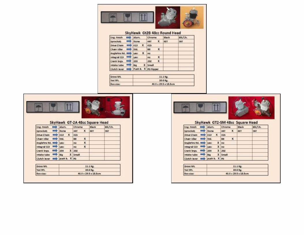
GT2A > 48cc / 40mm x 38mm bore and stroke: Center Fire Sq. Head.
GT2B > 48cc / 40mm x 38mm bore and stroke: Angle Fire Rd. Head.
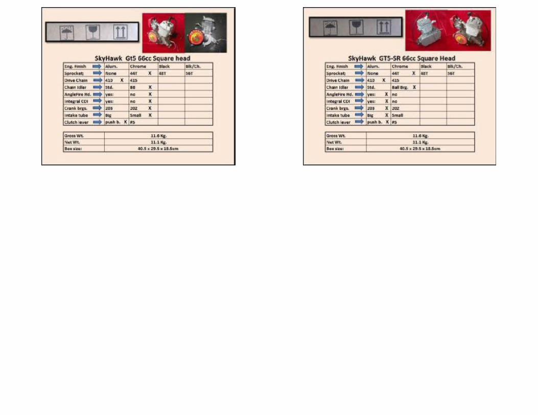
GT5 > 66cc / 47mm x 38mm bore and stroke: Angle Fire Sq. Head;
New; GT2-SM SuperMouse > 48cc: Internal CDI & 203 crank brgs. Angle Fire Sq. Head;
New: GT5-SR SuperRat > 66cc / Internal CDI & 203 crank brgs. Angle Fire Sq. Head;
Kit Box Contents: 2 cycle gas engine with dual needle bearing: Black Catalytic exhaust muffler; Tear Drop 2.5L Fuel Tank plated inside; Bicycle ½” x 1/8” drive chain; Chain
guard; 44 tooth Sprocket with 9 hole mounting hardware for 36 spoke wheel; Ball bearing chain idler: Push button clutch lever, CNS premium EPA approved
carburetor with external choke control: New design CD Ignition, Twist throttle with integral kill switch: Tool kit with Extra spark plug; Extra mt. block, Extra
head gasket:
To ensure engine performance: DO NOT use other than original SkyHawk replacement parts.
Note: Failing to follow these instructions when installing a certified engine in a piece of non-road equipment violates Federal Law 40CFR-1068.05 (b) and is
subject to fines or other penalties as described in the Clean Air Act of 1970. Mechanical aptitude and ability is required to perform this installation. Many “do it
yourself” backyard mechanics will find this project rewarding. A love of small engines is the only required catalyst for this project. However, installation is
sometimes best done by a professional auto or
motorcycle mechanic. Frame size should be 28mm to 30mm dia. with 70 degree included V angle. For sufficient engine clearance select a bike with a seat tube
length of at least 12 ½ inches measured between bottom of top tube and top of pedal sprocket tube. A rewarding joy and challenge is found in designing a
custom installation of your own. Remember, a quality installation is paramount to safe usage and long term satisfaction. You may find many uses for this
engine kit from stationary machine power to off road riding machines. Have fun and good luck on your motorized project.
STEP #1 Mounting the Engine: 1. The engine mounts in a “Vee” frame. It is best to make sure all 4 engine studs are securely bottomed out in the engine before mounting. Use a Jam nut
procedure to tighten.
2. Consider using Masking or Duct Tape on the front down-tube & seat tube of your bicycle to protect the paint finish while test fitting the engine to your donor
bike. If the distance between the two frame tubes exceeds the engine mounting span then additional spacers or welded brackets may be required. Mount the
engine to the seat tube first and then fit to the front tube. If frame tube fit is smaller than engine clamp dia. use strip shims to fit. See figure one for example of
installation on a wide frame bike..
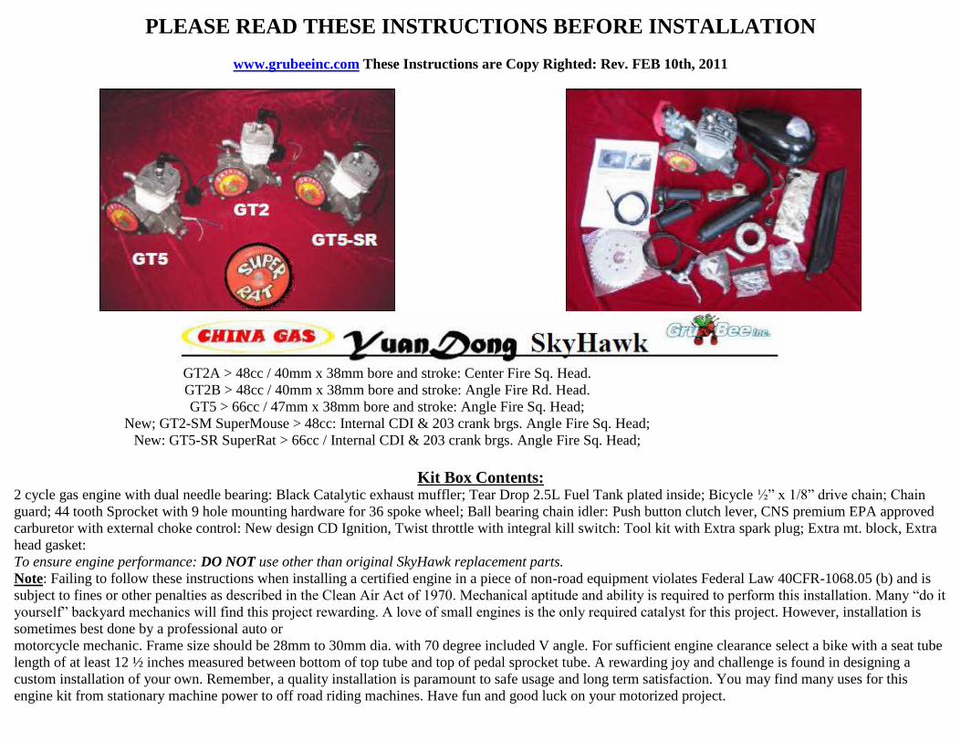
Special FrontMounting
When installing engine in a odd size frame it may be necessary to modify the existing front mount. This is due
to some oversized down tube frames being longer or wider then the motor is designed to fit.. If you find that the
front engine mount will not reach the down tube when the motor is mounted to rear tube you
will need to make modifications. You can use the extra mt. block found in the tool kit to space the engine
forward by cutting it to fit and installed it at the rear. Another idea is shown in the diagram at the right)
Figure 1. You will need a 3/16" X 1" flat steel bar 5 to 7 inches long. To determine the
length you will need attach the motor to the
rear (seat post) down tube. Measure underneath the motor on the frame to makes sure there
will be enough room to mount the bar on the motor
and meet the front mount of the engine. The length will also depend on the distance from
the frame to the motor.
Figure 2. Drill three holes in the flat bar. They will need to accept 6mm bolts or 1/4 US
thread depending on your choice of bolt. For the left hole use the furnished large down
tube adapter to determine placement of the hole. The measurements for the two right
wholes are an estimate and may vary with individual installations.
Figure 3. Bend the bar as shown in figure 3. The front, or left side must be bent up high
enough to connect to the mounting holes on the front of the
engine. It is important that the two bar ends are parallel to the frame not to each other.
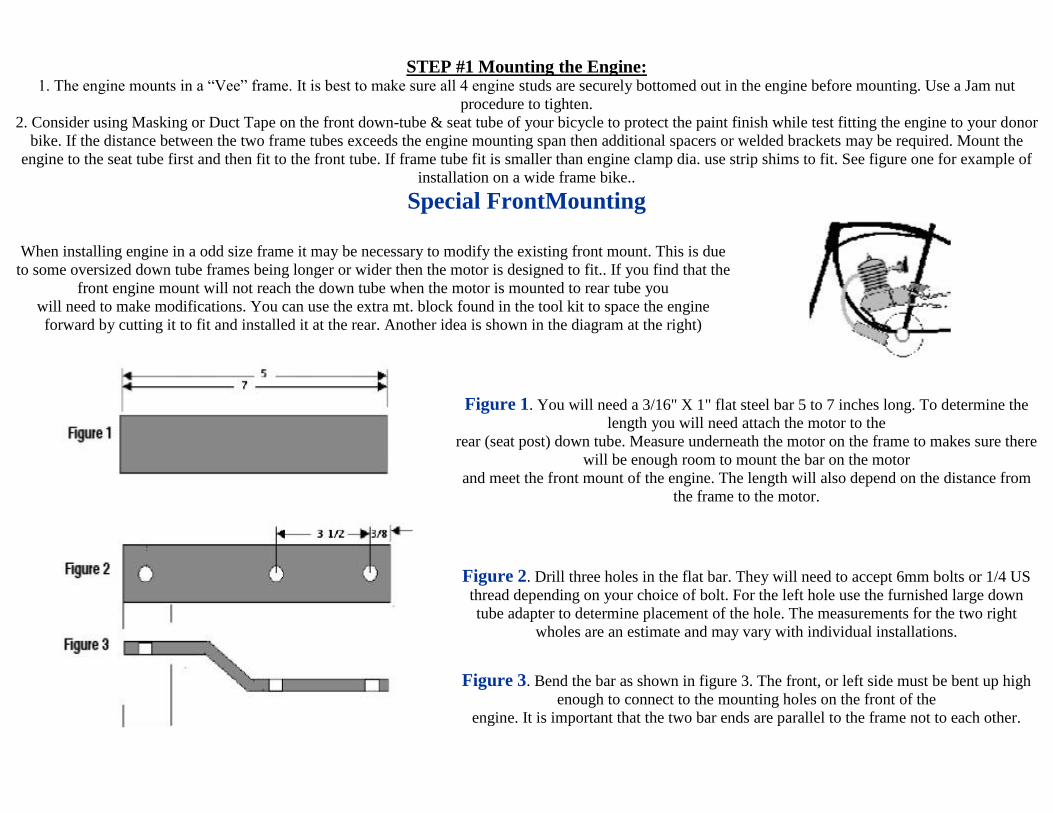
Figure 4. Align the furnished large tube adapter to the bar and mount to the bottom of the
bar. The bar will run through the space for the frame on the motor and the mounting holes
will rest on the adapter.
Figure 5. Mark where the mount will rest on the frame, be sure to line the mount up with
the frame so it is centered and straight.. Remove the motor from the frame. Drill two holes
through the frame using the finished mount as a guide. Bolt the mount to the frame. On the
bottom of the frame use half moon caliper brake mounting washers. Tighten the bolts
securely but do not over tighten or damage to the frame may occur . Use Lock-tite or
similar product on the bolts and buts along with lock washers.
MOUNT ENGINE IN FRAME as low as possible: AVOID BEING TOO HIGH UP IN THE FRAME.
If engine is mounted at a high angle position the chain will hit the sprocket cover. Keep as low as possible.
Remove front and rear fenders for safe operation: End user assumes all product liability as prime contractor:
Note: Quality Beach Cruiser bikes work good as well as do the classic 70 degree old time European style.
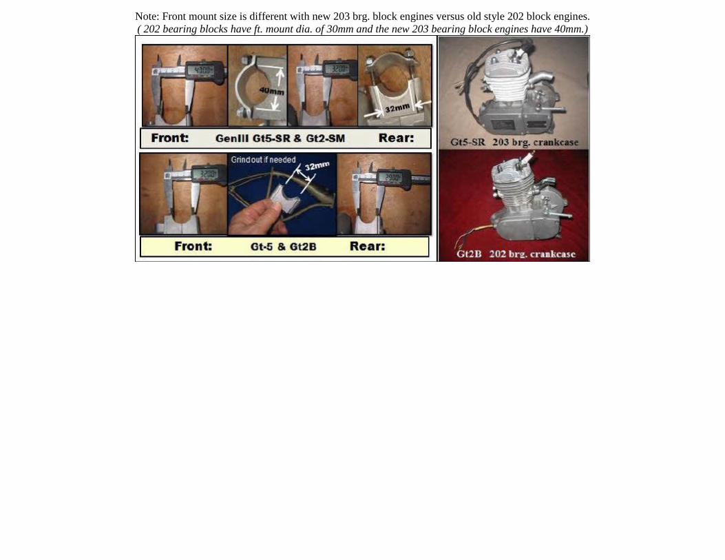
Note: Front mount size is different with new 203 brg. block engines versus old style 202 block engines.
( 202 bearing blocks have ft. mount dia. of 30mm and the new 203 bearing block engines have 40mm.)
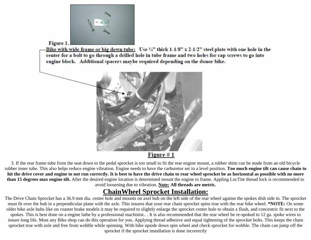
3. If the rear frame tube from the seat down to the pedal sprocket is too small to fit the rear engine mount, a rubber shim can be made from an old bicycle
rubber inner tube. This also helps reduce engine vibration. Engine needs to have the carburetor set in a level position. Too much engine tilt can cause chain to
hit the drive cover and engine to not run correctly. It is best to have the drive chain to rear wheel sprocket be as horizontal as possible with no more
than 15 degrees max engine tilt. After the desired engine location is determined mount the engine to frame. Appling LocTite thread lock is recommended to
avoid loosening due to vibration. Note: All threads are metric.
ChainWheel Sprocket Installation:
The Drive Chain Sprocket has a 36.9 mm dia. center hole and mounts on axel hub on the left side of the rear wheel against the spokes dish side in. The sprocket
must fit over the hub in a perpendicular plane with the axle. This insures that your rear chain sprocket spins true with the rear bike wheel. *NOTE: On some
older bike axle hubs like on coaster brake models it may be required to slightly enlarge the sprocket center hole to obtain a flush, and concentric fit next to the
spokes. This is best done on a engine lathe by a professional machinist.. . It is also recommended that the rear wheel be re-spoked to 12 ga. spoke wires to
insure long life. Most any Bike shop can do this operation for you. Applying thread adhesive and equal tightening of the sprocket bolts. This keeps the chain
sprocket true with axle and free from wobble while spinning. With bike upside down spin wheel and check sprocket for wobble. The chain can jump off the
sprocket if the sprocket installation is done incorrectly
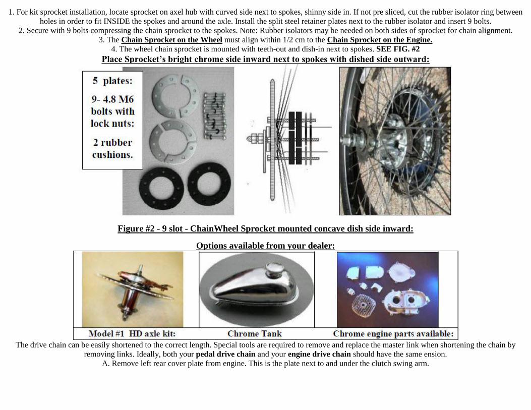
1. For kit sprocket installation, locate sprocket on axel hub with curved side next to spokes, shinny side in. If not pre sliced, cut the rubber isolator ring between
holes in order to fit INSIDE the spokes and around the axle. Install the split steel retainer plates next to the rubber isolator and insert 9 bolts.
2. Secure with 9 bolts compressing the chain sprocket to the spokes. Note: Rubber isolators may be needed on both sides of sprocket for chain alignment.
3. The Chain Sprocket on the Wheel must align within 1/2 cm to the Chain Sprocket on the Engine.
4. The wheel chain sprocket is mounted with teeth-out and dish-in next to spokes. SEE FIG. #2
Place Sprocket’s bright chrome side inward next to spokes with dished side outward:
Figure #2 - 9 slot - ChainWheel Sprocket mounted concave dish side inward:
Options available from your dealer:
The drive chain can be easily shortened to the correct length. Special tools are required to remove and replace the master link when shortening the chain by
removing links. Ideally, both your pedal drive chain and your engine drive chain should have the same ension.
A. Remove left rear cover plate from engine. This is the plate next to and under the clutch swing arm.
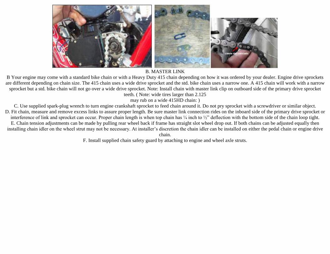
B. MASTER LINK
B Your engine may come with a standard bike chain or with a Heavy Duty 415 chain depending on how it was ordered by your dealer. Engine drive sprockets
are different depending on chain size. The 415 chain uses a wide drive sprocket and the std. bike chain uses a narrow one. A 415 chain will work with a narrow
sprocket but a std. bike chain will not go over a wide drive sprocket. Note: Install chain with master link clip on outboard side of the primary drive sprocket
teeth. ( Note: wide tires larger than 2.125
may rub on a wide 415HD chain: )
C. Use supplied spark-plug wrench to turn engine crankshaft sprocket to feed chain around it. Do not pry sprocket with a screwdriver or similar object.
D. Fit chain, measure and remove excess links to assure proper length. Be sure master link connection rides on the inboard side of the primary drive sprocket or
interference of link and sprocket can occur. Proper chain length is when top chain has ¼ inch to ½” deflection with the bottom side of the chain loop tight.
E. Chain tension adjustments can be made by pulling rear wheel back if frame has straight slot wheel drop out. If both chains can be adjusted equally then
installing chain idler on the wheel strut may not be necessary. At installer’s discretion the chain idler can be installed on either the pedal chain or engine drive
chain.
F. Install supplied chain safety guard by attaching to engine and wheel axle struts.
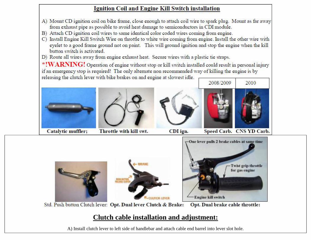
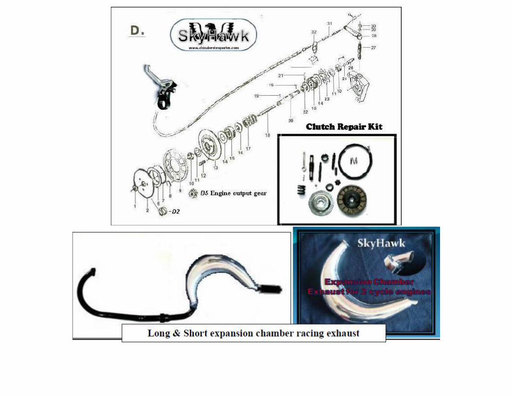
Clutch cable installation and adjustment:
A) Install clutch lever to left side of handlebar and attach cable end barrel into lever slot hole.
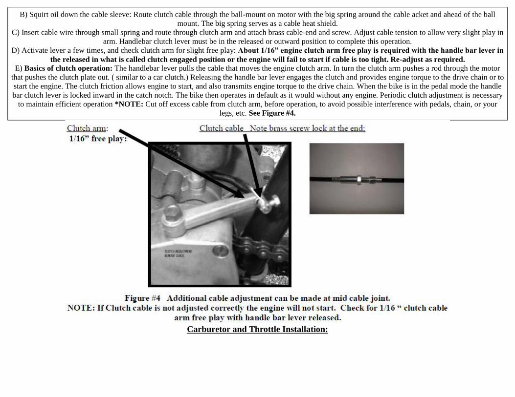
B) Squirt oil down the cable sleeve: Route clutch cable through the ball-mount on motor with the big spring around the cable acket and ahead of the ball
mount. The big spring serves as a cable heat shield.
C) Insert cable wire through small spring and route through clutch arm and attach brass cable-end and screw. Adjust cable tension to allow very slight play in
arm. Handlebar clutch lever must be in the released or outward position to complete this operation.
D) Activate lever a few times, and check clutch arm for slight free play: About 1/16” engine clutch arm free play is required with the handle bar lever in
the released in what is called clutch engaged position or the engine will fail to start if cable is too tight. Re-adjust as required. E) Basics of clutch operation: The handlebar lever pulls the cable that moves the engine clutch arm. In turn the clutch arm pushes a rod through the motor
that pushes the clutch plate out. ( similar to a car clutch.) Releasing the handle bar lever engages the clutch and provides engine torque to the drive chain or to
start the engine. The clutch friction allows engine to start, and also transmits engine torque to the drive chain. When the bike is in the pedal mode the handle
bar clutch lever is locked inward in the catch notch. The bike then operates in default as it would without any engine. Periodic clutch adjustment is necessary
to maintain efficient operation *NOTE: Cut off excess cable from clutch arm, before operation, to avoid possible interference with pedals, chain, or your
legs, etc. See Figure #4.
Carburetor and Throttle Installation:
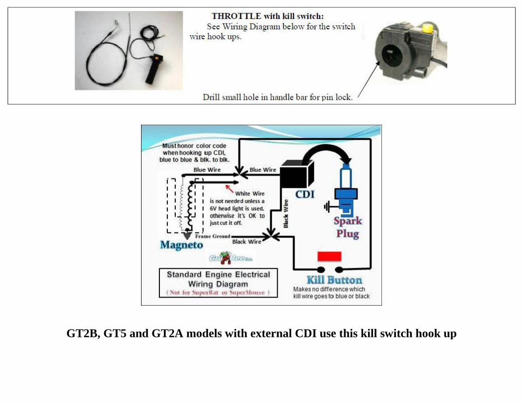
GT2B, GT5 and GT2A models with external CDI use this kill switch hook up
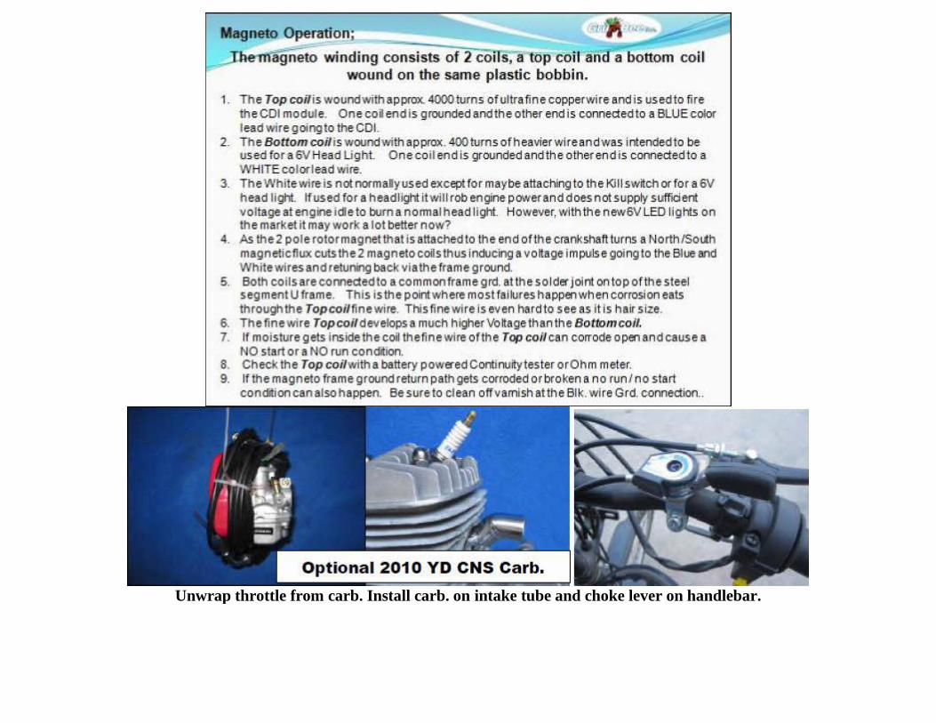
Unwrap throttle from carb. Install carb. on intake tube and choke lever on handlebar.
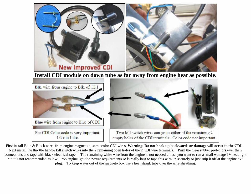
Install CDI module on down tube as far away from engine heat as possible.
First install Blue & Black wires from engine magneto to same color CDI wires. Warning: Do not hook up backwards or damage will occur to the CDI.
Next install the throttle handle kill switch wires into the 2 remaining open holes of the 2 CDI wire terminals. Push the clear rubber protectors over the 2
connections and tape with black electrical tape. The remaining white wire from the engine is not needed unless you want to run a small wattage 6V headlight
but it’s not recommended as it will rob engine ignition power requirements so is really best to tape this wire up securely or just snip it off at the engine exit
plug. To keep water out of the magneto box use a heat shrink tube over the wire sheathing.
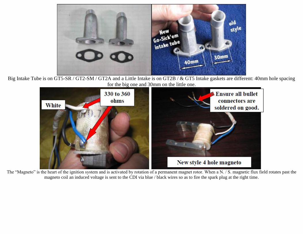
Big Intake Tube is on GT5-SR / GT2-SM / GT2A and a Little Intake is on GT2B / & GT5 Intake gaskets are different: 40mm hole spacing
for the big one and 30mm on the little one.
The “Magneto” is the heart of the ignition system and is activated by rotation of a permanent magnet rotor. When a N. / S. magnetic flux field rotates past the
magneto coil an induced voltage is sent to the CDI via blue / black wires so as to fire the spark plug at the right time.
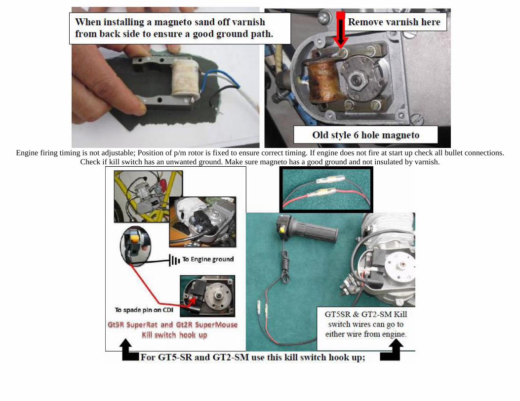
Engine firing timing is not adjustable; Position of p/m rotor is fixed to ensure correct timing. If engine does not fire at start up check all bullet connections.
Check if kill switch has an unwanted ground. Make sure magneto has a good ground and not insulated by varnish.
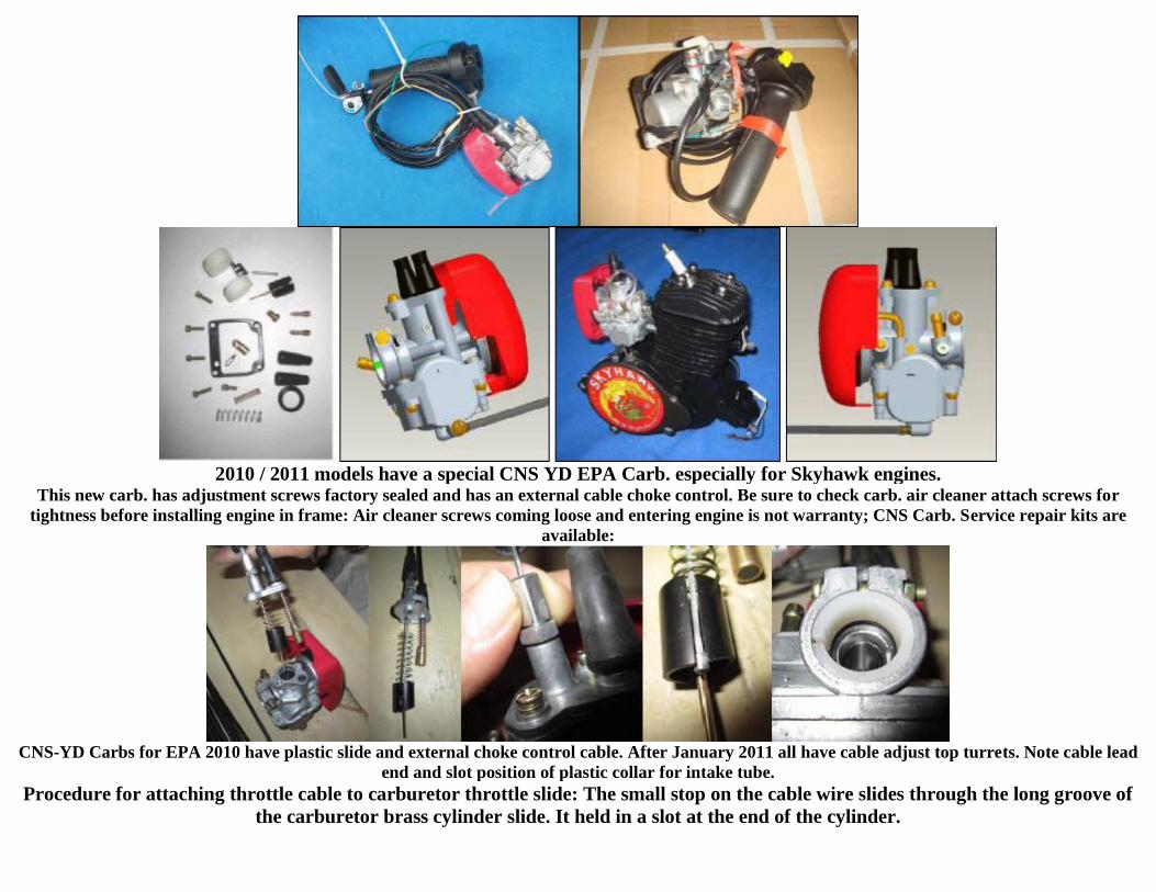
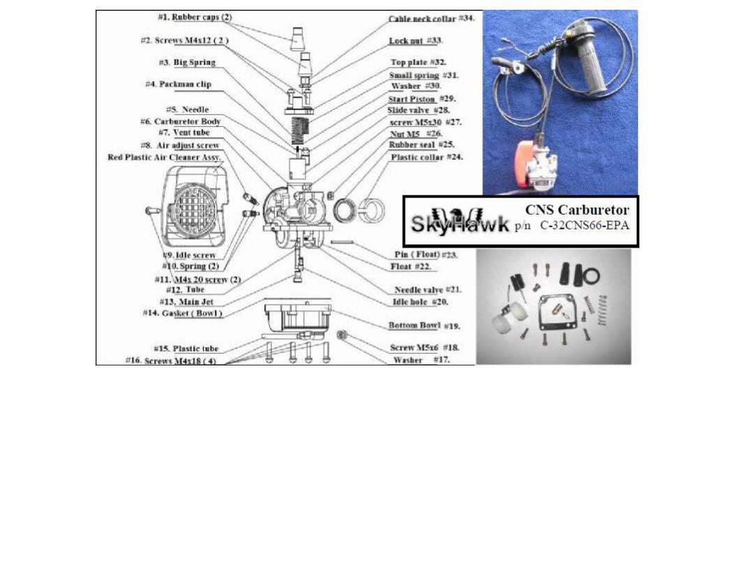
2010 / 2011 models have a special CNS YD EPA Carb. especially for Skyhawk engines. This new carb. has adjustment screws factory sealed and has an external cable choke control. Be sure to check carb. air cleaner attach screws for
tightness before installing engine in frame: Air cleaner screws coming loose and entering engine is not warranty; CNS Carb. Service repair kits are
available:
CNS-YD Carbs for EPA 2010 have plastic slide and external choke control cable. After January 2011 all have cable adjust top turrets. Note cable lead
end and slot position of plastic collar for intake tube.
Procedure for attaching throttle cable to carburetor throttle slide: The small stop on the cable wire slides through the long groove of
the carburetor brass cylinder slide. It held in a slot at the end of the cylinder.

( Note component positions in pictures: )
The spring is placed inside the cylinder slide and is compressed when the throttle is twisted. Be sure it is seated all the way inside the cylinder. The spring then
forces the throttle to return. For this to work properly the throttle must twist freely on the handle bar in both directions prior to the cable being installed.
A) Install twist grip throttle on right side of handlebar end. On some handle bars it may be necessary to ream out the handle ID to fit the bar so that the throttle
will twist freely. It never hurts to add a few drops of light wt. oil to let trickle down the cable inside the full length of sheathing.
B) After installing cable inside the carburetor you are ready to mount it on engine intake tube and tighten clamp screw. Mount engine so carburetor sets as level
as possible.
1. Note: Factory Sealed Air /Fuel ratio screw. Factory set by turning adjustment screw to closed position and then opened ¾ turns outward or less than 1 full
turn before it was sealed with epoxy.
2. Jet Needle comes with clip set in position #2 from the top. Different positions may be required to make your engine run correctly depending on altitude
above sea level and fuel economy desired. If a more rich gas mixture is required you can move the jet pin “pac man” clip to the next lower position notch.
SPEED CARB Note: Jet Needle comes with clip set in position #3 from the top. Different positions may be required to make your engine run correctly
depending on altitude above sea level and fuel economy desired. If a more rich gas mixture is required you can move the jet pin "pac man" clip to the next
lower position notch.
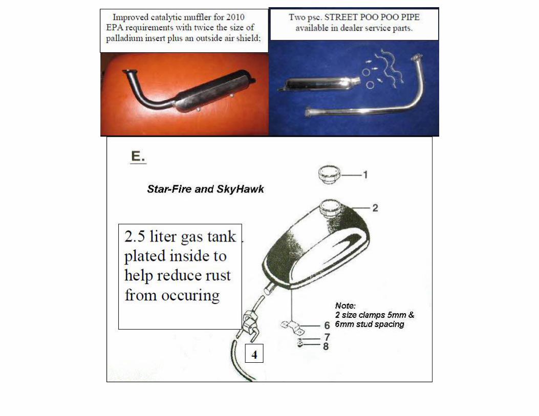
Fuel Tank installation
A) Attach fuel petcock to tank. Use Teflon tape to seal threads. Careful not to strip threads.
B) Mount tank on bike top crossover frame with two supplied brackets and nuts.
C) Attach fuel line from tank to carburetor. Best to use USA made fuel line like GoodYear SAE 30-7 4.8mm obtained from local automotive stores like
AutoZone. Factory supplied clear plastic line gets hard over a period of time. *NOTE: Filters are contained in the petcock and in the carburetor inlet. If engine
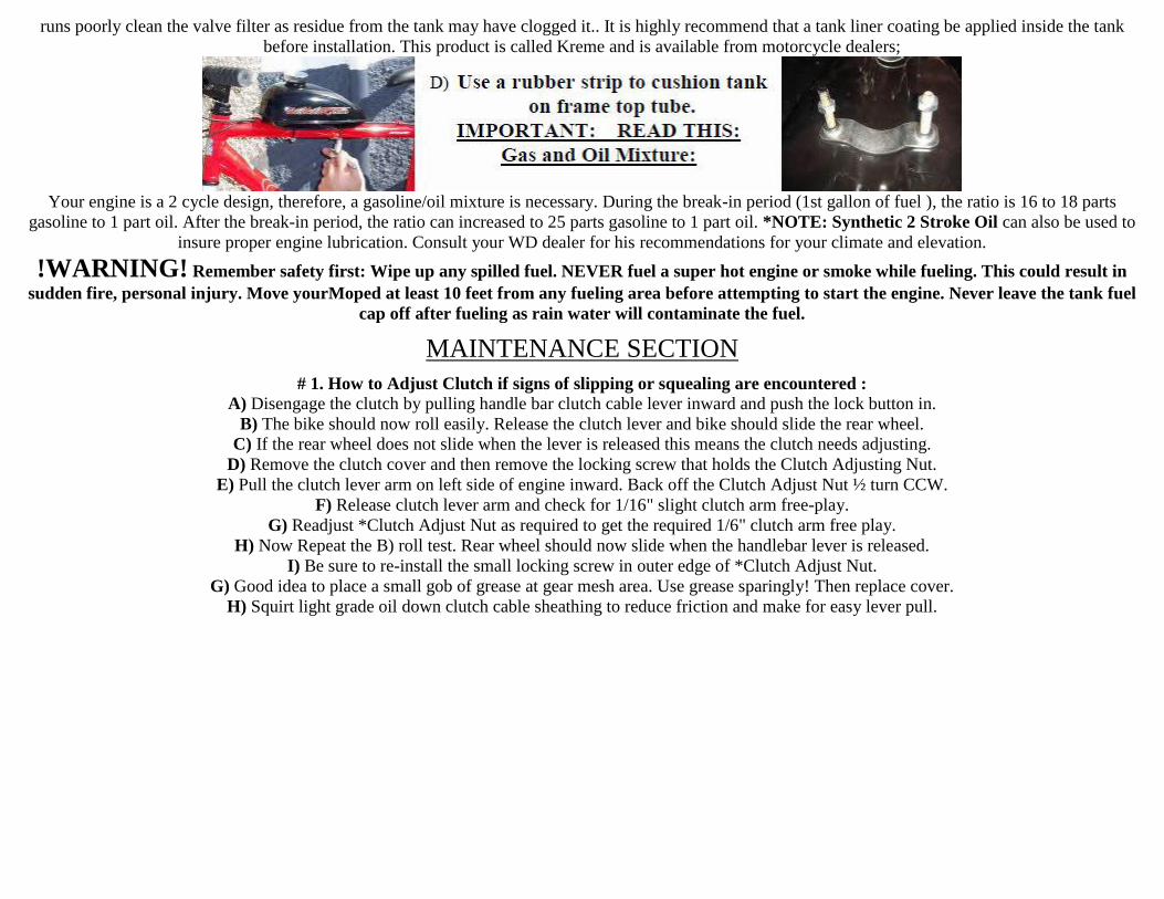
runs poorly clean the valve filter as residue from the tank may have clogged it.. It is highly recommend that a tank liner coating be applied inside the tank
before installation. This product is called Kreme and is available from motorcycle dealers;
Your engine is a 2 cycle design, therefore, a gasoline/oil mixture is necessary. During the break-in period (1st gallon of fuel ), the ratio is 16 to 18 parts
gasoline to 1 part oil. After the break-in period, the ratio can increased to 25 parts gasoline to 1 part oil. *NOTE: Synthetic 2 Stroke Oil can also be used to
insure proper engine lubrication. Consult your WD dealer for his recommendations for your climate and elevation.
!WARNING! Remember safety first: Wipe up any spilled fuel. NEVER fuel a super hot engine or smoke while fueling. This could result in
sudden fire, personal injury. Move yourMoped at least 10 feet from any fueling area before attempting to start the engine. Never leave the tank fuel
cap off after fueling as rain water will contaminate the fuel.
MAINTENANCE SECTION
# 1. How to Adjust Clutch if signs of slipping or squealing are encountered : A) Disengage the clutch by pulling handle bar clutch cable lever inward and push the lock button in.
B) The bike should now roll easily. Release the clutch lever and bike should slide the rear wheel.
C) If the rear wheel does not slide when the lever is released this means the clutch needs adjusting.
D) Remove the clutch cover and then remove the locking screw that holds the Clutch Adjusting Nut.
E) Pull the clutch lever arm on left side of engine inward. Back off the Clutch Adjust Nut ½ turn CCW.
F) Release clutch lever arm and check for 1/16" slight clutch arm free-play.
G) Readjust *Clutch Adjust Nut as required to get the required 1/6" clutch arm free play.
H) Now Repeat the B) roll test. Rear wheel should now slide when the handlebar lever is released.
I) Be sure to re-install the small locking screw in outer edge of *Clutch Adjust Nut.
G) Good idea to place a small gob of grease at gear mesh area. Use grease sparingly! Then replace cover.
H) Squirt light grade oil down clutch cable sheathing to reduce friction and make for easy lever pull.
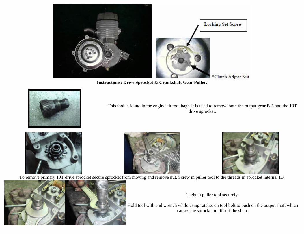
Instructions: Drive Sprocket & Crankshaft Gear Puller.
This tool is found in the engine kit tool bag: It is used to remove both the output gear B-5 and the 10T
drive sprocket.
To remove primary 10T drive sprocket secure sprocket from moving and remove nut. Screw in puller tool to the threads in sprocket internal ID.
Tighten puller tool securely;
Hold tool with end wrench while using ratchet on tool bolt to push on the output shaft which
causes the sprocket to lift off the shaft.
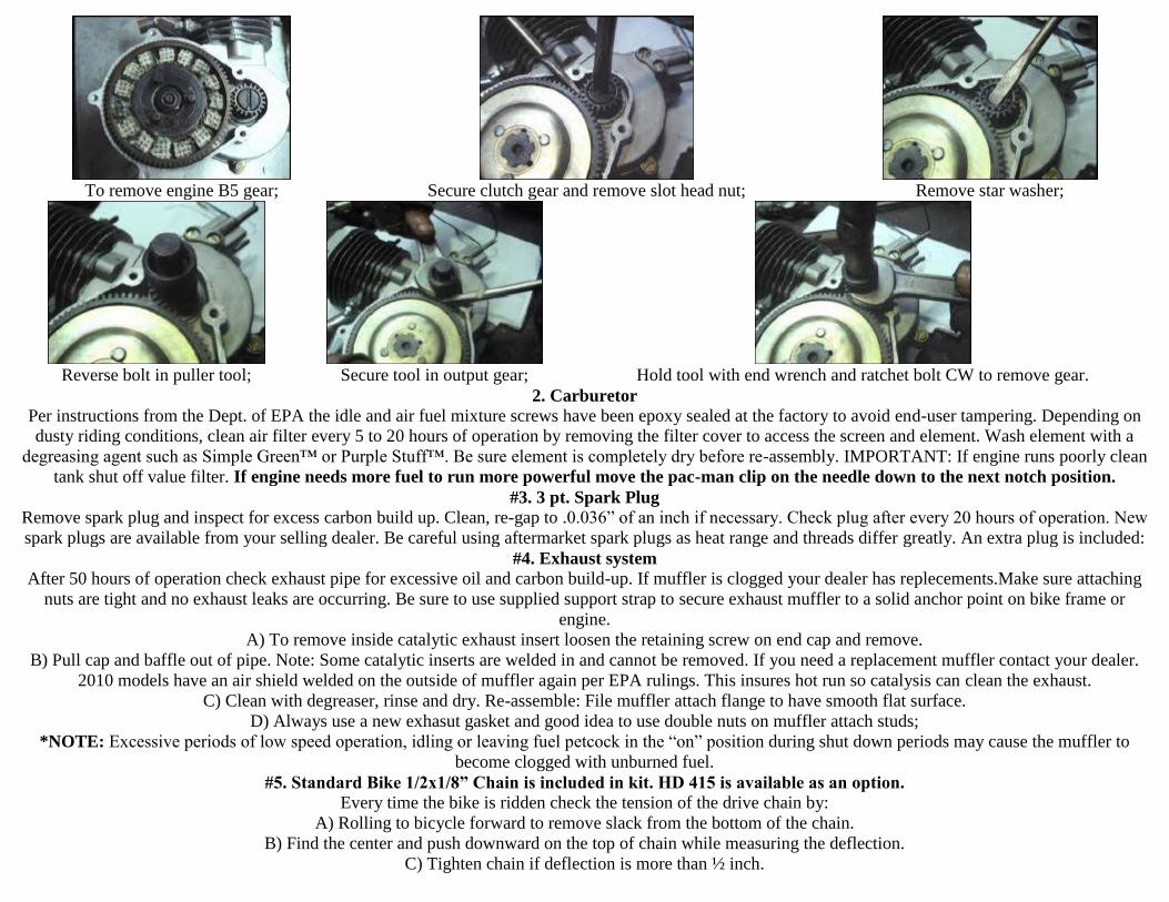
To remove engine B5 gear; Secure clutch gear and remove slot head nut; Remove star washer;
Reverse bolt in puller tool; Secure tool in output gear; Hold tool with end wrench and ratchet bolt CW to remove gear.
2. Carburetor Per instructions from the Dept. of EPA the idle and air fuel mixture screws have been epoxy sealed at the factory to avoid end-user tampering. Depending on
dusty riding conditions, clean air filter every 5 to 20 hours of operation by removing the filter cover to access the screen and element. Wash element with a
degreasing agent such as Simple Green™ or Purple Stuff™. Be sure element is completely dry before re-assembly. IMPORTANT: If engine runs poorly clean
tank shut off value filter. If engine needs more fuel to run more powerful move the pac-man clip on the needle down to the next notch position.
#3. 3 pt. Spark Plug Remove spark plug and inspect for excess carbon build up. Clean, re-gap to .0.036” of an inch if necessary. Check plug after every 20 hours of operation. New
spark plugs are available from your selling dealer. Be careful using aftermarket spark plugs as heat range and threads differ greatly. An extra plug is included:
#4. Exhaust system After 50 hours of operation check exhaust pipe for excessive oil and carbon build-up. If muffler is clogged your dealer has replecements.Make sure attaching
nuts are tight and no exhaust leaks are occurring. Be sure to use supplied support strap to secure exhaust muffler to a solid anchor point on bike frame or
engine.
A) To remove inside catalytic exhaust insert loosen the retaining screw on end cap and remove.
B) Pull cap and baffle out of pipe. Note: Some catalytic inserts are welded in and cannot be removed. If you need a replacement muffler contact your dealer.
2010 models have an air shield welded on the outside of muffler again per EPA rulings. This insures hot run so catalysis can clean the exhaust.
C) Clean with degreaser, rinse and dry. Re-assemble: File muffler attach flange to have smooth flat surface.
D) Always use a new exhasut gasket and good idea to use double nuts on muffler attach studs;
*NOTE: Excessive periods of low speed operation, idling or leaving fuel petcock in the “on” position during shut down periods may cause the muffler to
become clogged with unburned fuel.
#5. Standard Bike 1/2x1/8” Chain is included in kit. HD 415 is available as an option. Every time the bike is ridden check the tension of the drive chain by:
A) Rolling to bicycle forward to remove slack from the bottom of the chain.
B) Find the center and push downward on the top of chain while measuring the deflection.
C) Tighten chain if deflection is more than ½ inch.
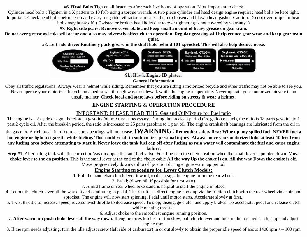
#6. Head Bolts Tighten all fasteners after each five hours of operation. Most important to check
Cylinder head bolts : Tighten in a X pattern to 10 ft/lb using a torque wrench. A two piece cylinder and head design engine requires head bolts be kept tight.
Important: Check head bolts before each and every long ride, vibration can cause them to loosen and blow a head gasket. Caution: Do not over torque or head
bolts may break off. ( Twisted or broken head bolts due to over tightening is not covered by warranty. )
#7. Right side gears: Remove cover plate and keep small amount of heavy grease on gear train.
Do not over grease as leaks will occur and also may adversely affect clutch operation. Regular greasing will help reduce gear wear and keep gear train
quiet.
#8. Left side drive: Routinely pack grease in the shaft hole behind 10T sprocket. This will also help deduce noise.
General Information Obey all traffic regulations. Always wear a helmet while riding. Remember that you are riding a motorized bicycle and other traffic may not be able to see you.
Never operate your motorized bicycle on a pedestrian through way or sidewalk while the engine is operating. Never operate your motorized bicycle in an
unsafe manner. Check local and state laws before riding on streets & wear a helmet.
ENGINE STARTING & OPERATION PROCEDURE
IMPORTANT: PLEASE READ THIS: Gas and OilMixture for Fuel ratio
The engine is a 2 cycle design, therefore, a gasoline/oil mixture is necessary. During the break-in period (1st gallon of fuel), the ratio is 18 parts gasoline to 1
part 2 cycle oil. After the break-in period, the ratio is increased to 25 parts gasoline to 1 part oil. The engine crankshaft bearings are lubricated from the oil in
the gas mix. A rich break in mixture ensures bearings will not cease. !WARNING! Remember safety first: Wipe up any spilled fuel. NEVER fuel a
hot engine or light a cigarette while fueling. This could result in sudden fire, personal injury. Always move your motorized bike at least 10 feet from
any fueling area before attempting to start it. Never leave the tank fuel cap off after fueling as rain water will contaminate the fuel and cause engine
failure. Step #1. After filling tank with the correct oil/gas mix open the tank fuel valve. Fuel line is in the open position when the small lever is pointed down. Move
choke lever to the on position. This is the small lever at the end of the choke cable All the way Up the choke is on. All the way Down the choke is off.
Move progressively downward to off position during engine warm up period.
Engine Starting procedure for Lever Clutch Models:
1. Pull the handlebar clutch lever inward, to disengage the engine from the rear wheel.
2. Pedal; (down hill if possible for first start)
3. A mid frame or rear wheel bike stand is helpful to start the engine in place.
4. Let out the clutch lever all the way out and continuing to pedal. The result is a direct engine hook up via the friction clutch with the rear wheel via chain and
sprocket. The engine will now start spinning, Pedal until motor starts. Accelerate slowly at first..
5. Twist throttle to increase speed, reverse twist throttle to decrease speed. To stop, disengage clutch and apply brakes. To accelerate, pedal and release clutch
while opening throttle.
6. Adjust choke to the smoothest engine running position.
7. After warm up push choke lever all the way down. If engine races too fast, or too slow, pull clutch lever and lock in the notched catch, stop and adjust
engine rpm.
8. If the rpm needs adjusting, turn the idle adjust screw (left side of carburetor) in or out slowly to obtain the proper idle speed of about 1400 rpm +/- 100 rpm
To correctly break the engine in, Do not exceed 15 mph or 30 min. continual running for the first 50 miles during engine brake in. Engine will develop more
power after break in.
9. To stop the engine, push Kill switch and turn off gas valve at tank. Turning off the gas will prevent fuel from being siphoned from tank. Warning Note:
Never leave the tank gas valve in “open” position” when engine is not running or the bike is in storage.
10. After or before each ride check all mounting fasteners, including hd. Bolts, axle and brakes.
11. Warning Note: Engine lock up or piston seizure due to improper gas / oil mixture will not be covered by factory warranty. This the responsibility of the
owner / operator to make sure the gas and oil is mixed correctly.
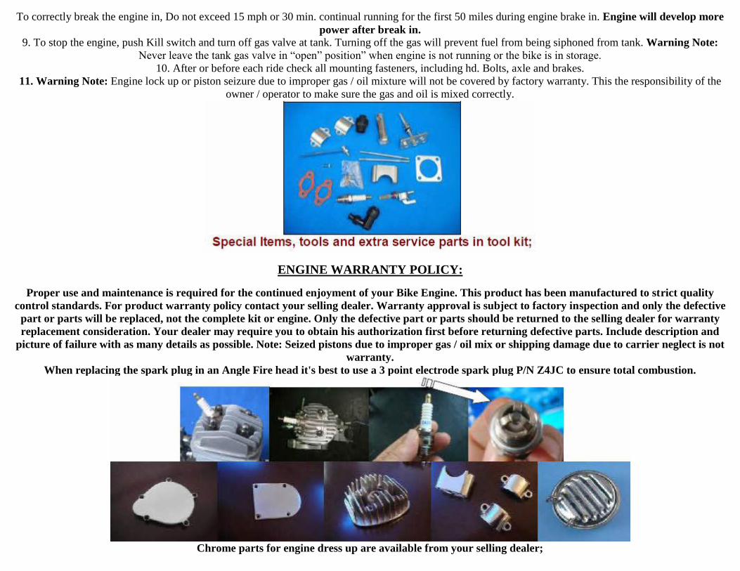
ENGINE WARRANTY POLICY:
Proper use and maintenance is required for the continued enjoyment of your Bike Engine. This product has been manufactured to strict quality
control standards. For product warranty policy contact your selling dealer. Warranty approval is subject to factory inspection and only the defective
part or parts will be replaced, not the complete kit or engine. Only the defective part or parts should be returned to the selling dealer for warranty
replacement consideration. Your dealer may require you to obtain his authorization first before returning defective parts. Include description and
picture of failure with as many details as possible. Note: Seized pistons due to improper gas / oil mix or shipping damage due to carrier neglect is not
warranty.
When replacing the spark plug in an Angle Fire head it's best to use a 3 point electrode spark plug P/N Z4JC to ensure total combustion.
Chrome parts for engine dress up are available from your selling dealer;
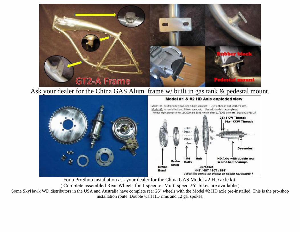
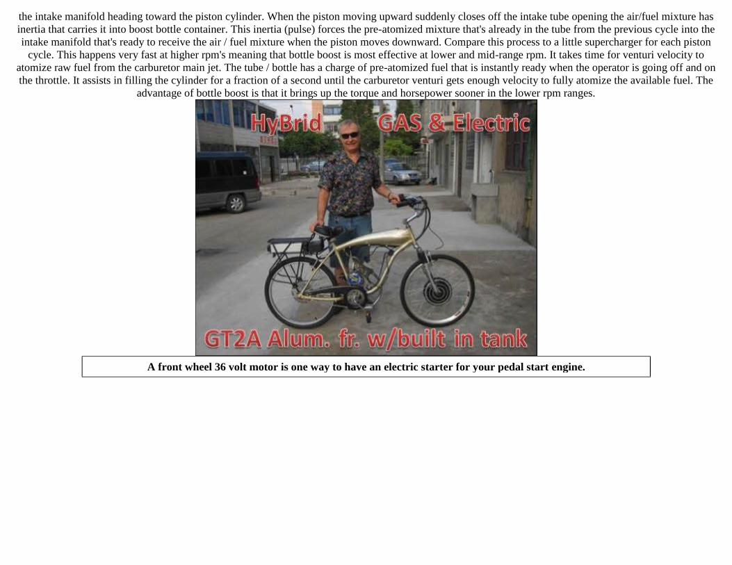
Ask your dealer for the China GAS Alum. frame w/ built in gas tank & pedestal mount.
For a ProShop installation ask your dealer for the China GAS Model #2 HD axle kit;
( Complete assembled Rear Wheels for 1 speed or Multi speed 26” bikes are available.)
Some SkyHawk WD distributors in the USA and Australia have complete rear 26" wheels with the Model #2 HD axle pre-installed. This is the pro-shop
installation route. Double wall HD rims and 12 ga. spokes.
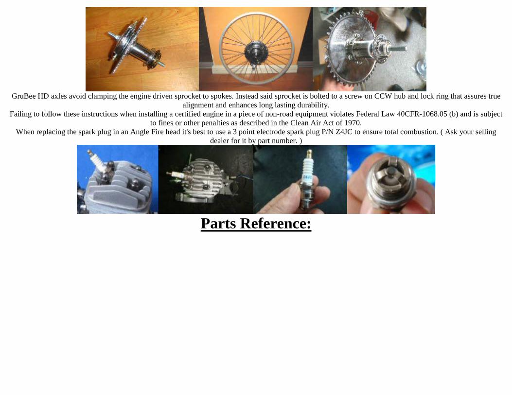
GruBee HD axles avoid clamping the engine driven sprocket to spokes. Instead said sprocket is bolted to a screw on CCW hub and lock ring that assures true
alignment and enhances long lasting durability.
Failing to follow these instructions when installing a certified engine in a piece of non-road equipment violates Federal Law 40CFR-1068.05 (b) and is subject
to fines or other penalties as described in the Clean Air Act of 1970.
When replacing the spark plug in an Angle Fire head it's best to use a 3 point electrode spark plug P/N Z4JC to ensure total combustion. ( Ask your selling
dealer for it by part number. )
Parts Reference:
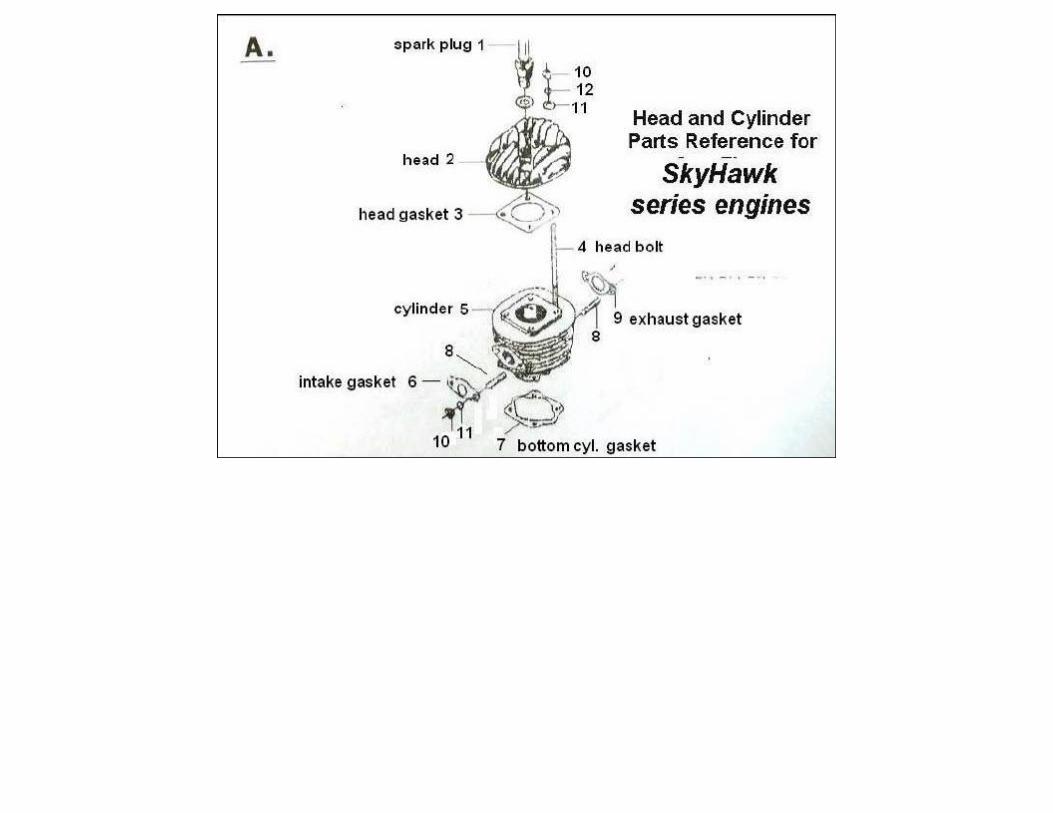
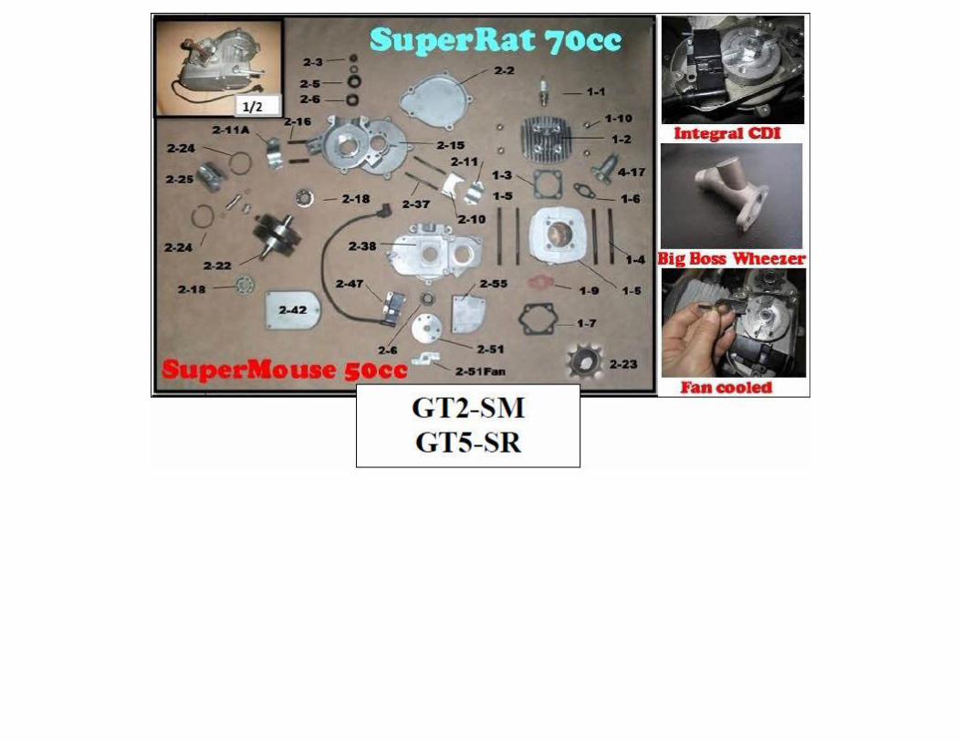
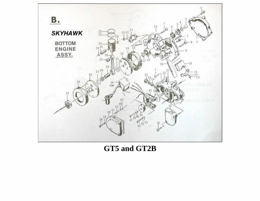
GT5 and GT2B
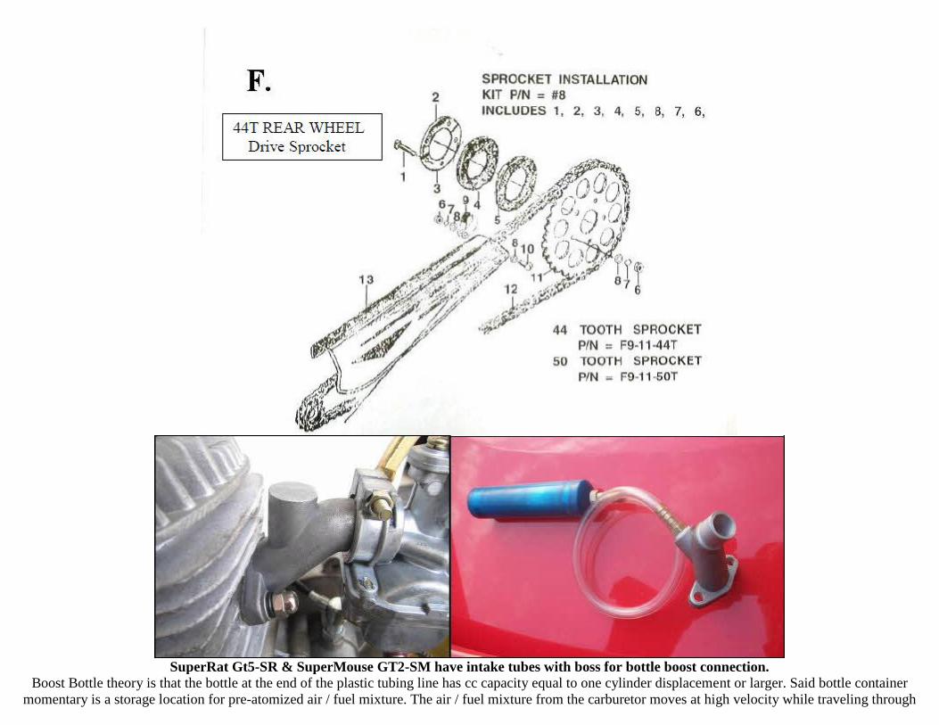
SuperRat Gt5-SR & SuperMouse GT2-SM have intake tubes with boss for bottle boost connection. Boost Bottle theory is that the bottle at the end of the plastic tubing line has cc capacity equal to one cylinder displacement or larger. Said bottle container
momentary is a storage location for pre-atomized air / fuel mixture. The air / fuel mixture from the carburetor moves at high velocity while traveling through
the intake manifold heading toward the piston cylinder. When the piston moving upward suddenly closes off the intake tube opening the air/fuel mixture has
inertia that carries it into boost bottle container. This inertia (pulse) forces the pre-atomized mixture that's already in the tube from the previous cycle into the
intake manifold that's ready to receive the air / fuel mixture when the piston moves downward. Compare this process to a little supercharger for each piston
cycle. This happens very fast at higher rpm's meaning that bottle boost is most effective at lower and mid-range rpm. It takes time for venturi velocity to
atomize raw fuel from the carburetor main jet. The tube / bottle has a charge of pre-atomized fuel that is instantly ready when the operator is going off and on
the throttle. It assists in filling the cylinder for a fraction of a second until the carburetor venturi gets enough velocity to fully atomize the available fuel. The
advantage of bottle boost is that it brings up the torque and horsepower sooner in the lower rpm ranges.
A front wheel 36 volt motor is one way to have an electric starter for your pedal start engine.
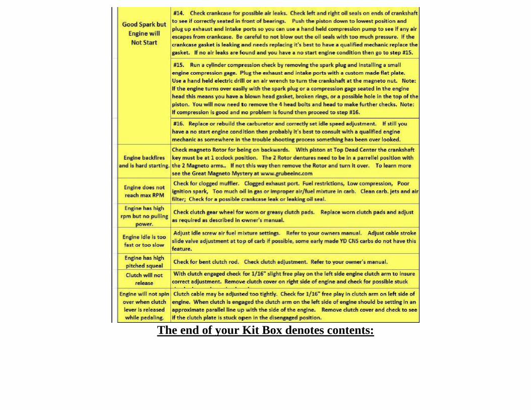
The end of your Kit Box denotes contents: