Embed Size (px)
Citation preview
PLEASE SCROLL DOWN FOR ARTICLE
This article was downloaded by: [Jordan University of Science & Technology]On: 4 October 2009Access details: Access Details: [subscription number 791509110]Publisher Taylor & FrancisInforma Ltd Registered in England and Wales Registered Number: 1072954 Registered office: Mortimer House,37-41 Mortimer Street, London W1T 3JH, UK
International Journal of ElectronicsPublication details, including instructions for authors and subscription information:http://www.informaworld.com/smpp/title~content=t713599654
Cylindrical CPW-fed and CPS-fed slot antennasAmjad A. Omar a; Maximilian C. Scardelletti b; Nihad Dib c; Raed Shubair d
a Hijjawi Faculty of Engineering Technology, Department of Communications Engineering, YarmoukUniversity, Irbid, Jordan b NASA Glenn Research Center, Cleveland, Ohio, USA c Department of ElectricalEngineering, Jordan University of Science and Technology, Irbid, Jordan d Communications EngineeringDepartment, Khalifa University of Science, Technology and Research, Sharjah, United Arab Emirates
First Published:April2009
To cite this Article Omar, Amjad A., Scardelletti, Maximilian C., Dib, Nihad and Shubair, Raed(2009)'Cylindrical CPW-fed and CPS-fedslot antennas',International Journal of Electronics,96:4,397 — 407
To link to this Article: DOI: 10.1080/00207210802654455
URL: http://dx.doi.org/10.1080/00207210802654455
Full terms and conditions of use: http://www.informaworld.com/terms-and-conditions-of-access.pdf
This article may be used for research, teaching and private study purposes. Any substantial orsystematic reproduction, re-distribution, re-selling, loan or sub-licensing, systematic supply ordistribution in any form to anyone is expressly forbidden.
The publisher does not give any warranty express or implied or make any representation that the contentswill be complete or accurate or up to date. The accuracy of any instructions, formulae and drug dosesshould be independently verified with primary sources. The publisher shall not be liable for any loss,actions, claims, proceedings, demand or costs or damages whatsoever or howsoever caused arising directlyor indirectly in connection with or arising out of the use of this material.
Cylindrical CPW-fed and CPS-fed slot antennas
Amjad A. Omara*, Maximilian C. Scardellettib, Nihad Dibc and Raed Shubaird
aHijjawi Faculty of Engineering Technology, Department of Communications Engineering, YarmoukUniversity, Irbid, Jordan; bNASA Glenn Research Center, Cleveland, Ohio; USA; cDepartment of
Electrical Engineering, Jordan University of Science and Technology, Irbid, Jordan; dCommunicationsEngineering Department, Khalifa University of Science, Technology and Research, Sharjah, United
Arab Emirates
(Received 15 November 2007; final version received 31 October 2008)
Cylindrical antennas are needed in applications which require mounting on curvedsurfaces. This article presents two new designs of antennas printed on cylindricalsubstrates. The first antenna is a dual frequency coplanar waveguide (CPW)-fed doublefolded slot antenna operating at 5 and 7 GHz. This antenna is matched to the feed linewithout external matching circuitry and exhibits a gain of about 3.2 dBi. It has abidirectional pattern in the E-plane and a more omnidirectional pattern in the H-plane.The second antenna is a coplanar strips (CPS)-fed folded slot antenna operating at7 GHz. Its gain is about 2.56 dBi. The experimental and numerical results are providedfor the return loss and radiation patterns with good agreement.
Keywords: antennas; CAD; electromagnetic analysis; microwave; frequency analysis
1. Introduction
Antennas with cylindrical geometry can offer certain desirable antenna characteristics thatare not provided by antennas with planar geometry. In particular, they can be easilymounted on curved surfaces such as aircraft and missiles. Several designs of microstripantennas on cylindrical substrates are available in the literature (Nakatani andAlexopoulos 1986; Silva, Fonseca, Soares and Giarola 1991; Lin-Lu and Shyh-Yeong1993; Jain-Ming, Berrie, Kipp and Lee 1997; Vecchi, Bertuch and Orefice 1997;Keskilammi and Kivikoski 2003; Hong, Li, Lin and Kitazawa 2006; Hoorfar, Guptaand Chang 2007; Wang, Zhu, Yun and Xu 2007). However, the study of coplanarwaveguides (CPW) on cylindrical substrates has mainly focussed on analysing the CPWdispersion (Hsin-Cheng and Kin-Lu 1996; Al-Zoubi, Obeidat and Dib 1999; Dib, Weller,Scardelletti and Imparto 1999; Omar 2001; Lieh-Chuan, Lin and Kitazawa 2007) with fewCPW antenna designs. To this end, Kim, Nikolaou, Ponchak, Kim, Papapolymeru andTentzeris (2006) proposed a single band CPW-fed monopole antenna etched on acylindrical substrate. Scardelletti, Dib, Weller, Culver and King (2005) proposed twodesigns of single band CPW-fed slot antenna and CPW-fed folded slot antenna oncylindrical substrate. A compact single band antenna on a cylindrical substrate consistingof a CPW line feeding a dipole used for ultra wideband applications was proposed (USpatent 2006).
*Corresponding author. Email: [email protected]
International Journal of Electronics
Vol. 96, No. 4, April 2009, 395–405
ISSN 0020-7217 print/ISSN 1362-3060 online
� 2009 Taylor & Francis
DOI: 10.1080/00207210802654455
http://www.informaworld.com
Downloaded By: [Jordan University of Science & Technology] At: 13:16 4 October 2009
Cylindrical antennas with dual capability are particularly useful in applications whichtake advantage of multiple carrier frequencies to increase data rates and relax systemrequirements, such as in radar and satellite systems. A lot of research work has targetedthis subject but has mainly concentrated on the design of dual band antennas on planarsubstrates. To this end, Surjati, Rahardjo and Hartano (2006) proposed a dual bandtriangular microstrip antenna fed by CPW. Vandenbosch, Beyne, Brebels amd Soliman(1998) produced a dual band Cusp antenna fed by CPW. Belguessoum and Delisle (2005)proposed a dual band antenna consisting of a CPW-fed slotted patch antenna, Omar andAntar (2001) proposed a double folded slot antenna on a planar substrate which uses multistubs for matching. Omar, Scardelletti, Hejaze and Dib (2007) proposed a dual bandCPW-fed double folded slot antenna on a planar substrate, where matching is achieved byincreasing the width of the folded slots. Hettak, Delisle and Stubbs (2003) proposed a dualband CPW-fed-aperture coupled-patch antenna. Liu and Wu (2004) proposed a CPW-fedplanar monopole antenna with a notch.
As far as CPS antennas are concerned very little work has been done on this subject.Tilley, Wu and Chang (1994) proposed a coplanar waveguide fed coplanar strip dipolematched using a balun on a planar substrate.
In this article, two types of cylindrical antennas are proposed. The first type is acylindrical coplanar waveguide (CCPW)-fed dual-frequency double folded slot antennathat employs a self-matching technique to reduce the complexity and size. We have notbeen able to locate any paper that deals with the design of CPW fed antennas on cylidricalsubstrates with dual band capability. The second antenna to be proposed in this article is asingle band cylindrical coplanar stripline (CCPS)-fed folded slot antenna. The CCPS is thedual structure of CCPW, and therefore has all the advantages of CCPW, and it makesefficient use of the wafer area. Simulated and measured results for the two antennas arepresented.
2. CPW feed design equations (Wong 1999)
In choosing the dimensions of the antenna’s CPW feed and the folded slot dimensions, useis made of the closed form quasi-static expressions of the effective dielectric constantand characteristic impedance of CPW on cylindrical substrates derived by Wong (1999)(see Figure 1 for the cross-sectional view of the CPW feed). These expressions are:
eeff ¼ 1þ ðe1 � 1Þ2
Kffiffiffiffiffiffiffiffiffiffiffiffiffi1� k21
q� �Kðk1Þ
Kðk2Þ
Kffiffiffiffiffiffiffiffiffiffiffiffiffi1� k22
q� � ð1Þ
Z0 ¼30pffiffiffiffiffiffieeffp
Kffiffiffiffiffiffiffiffiffiffiffiffiffi1� k21
q� �Kðk1Þ
ð2Þ
where
k1 ¼S
Sþ 2W
ffiffiffiffiffiffiffiffiffiffiffiffiffiffiffiffiffiffiffiffiffiffiffiffiffiffiffiffiffiffiffiffiffiffiffiffiffiffiffiffiffiffiffiffi1� ðSþ 2WÞ2=4b2p2
1� S2=4b2p2
sð3Þ
396 A.A. Omar et al.
Downloaded By: [Jordan University of Science & Technology] At: 13:16 4 October 2009

k2 ¼sin hðASÞ
sin hðAðSþ 2WÞÞ
ffiffiffiffiffiffiffiffiffiffiffiffiffiffiffiffiffiffiffiffiffiffiffiffiffiffiffiffiffiffiffiffiffiffiffiffiffiffiffiffiffiffiffiffiffiffiffiffiffiffiffiffiffiffiffiffiffiffiffiffiffiffiffiffiffiffiffiffiffiffiffiffiffi1� sin h2½AðSþ 2WÞ�=sinh2ð2AbpÞ
1� sin h2ðASÞ=sin h2ð2AbpÞ
sð4Þ
A ¼ p4b ln b
a
ð5Þ
S, W are the centre conductor width and slot width of the CPW feed, b is the outer radiusof the dielectric cylinder, a is the inner radius of the dielectric cylinder, as shown inFigure 1 and K is the complete elliptic integral of the first kind (Wong 1999). In our design,the inner radius a is zero.
Figure 2. Microphotograph of the CCPW-fed slot antenna illustrating CPW feed line and SMAconnector. The substrate is a teflon rod (er ¼ 2.2) with a diameter of 12.7 mm.
Figure 1. Cross-sectional view of the cylindrical coplanar waveguide feed (Wong 1999) (in ourdesign, a ¼ 0).
International Journal of Electronics 397
Downloaded By: [Jordan University of Science & Technology] At: 13:16 4 October 2009

3. Cylindrical dual-frequency CPW-fed slot antenna (CCPW)
The aim of this section is to design an antenna that can operate at two frequency bandscentred at *5 and 7 GHz. The targeted antenna is built on a cylindrical substrate made ofTeflon rod (er ¼ 2.2) with a diameter of 12.7 mm (0.5 in.), as shown in Figure 2. The CPWfeed is chosen to have an impedance of 70 W. From Equation (2), this corresponds to acentre conductor width (S) of 1.7 mm a slot width (W) of 0.3 mm. From Equation (1), theCPW line effective dielectric constant (eeff) is 1.6. A 70 W feed is chosen instead of 50 Wfeed because the latter requires a very narrow slot of w ¼ 0.07 mm and we do not have thecapability to fabricate these narrow slots in-house.
The proposed antenna topology consists of inner and outer folded slots. Thecircumference of the inner slot is chosen to be approximately one wavelength at the centre ofthe upper frequency band (at 7 GHz) (Lopez-Rivera and Rodrigues-Solis, 2002). Knowing
Figure 3. Surface view of the cylindrical CPW-fed dual band antenna showing detailed dimensions.(W ¼ 0.3 mm, S ¼ 1.7 mm, S0 ¼ 0.46 mm, W0 ¼ 0.35 mm, W00 ¼ 1.36 mm, L ¼ 16.7 mm,L0 ¼ 22.57 mm, all dimensions are in millimetres).
Figure 4. Return loss for the CCPW antenna. The simulations are performed using HFSS.
398 A.A. Omar et al.
Downloaded By: [Jordan University of Science & Technology] At: 13:16 4 October 2009
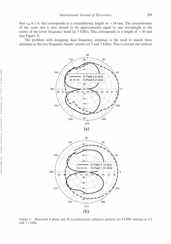
that eeff is 1.6, this corresponds to a circumference length of *34 mm. The circumferenceof the outer slot is also chosen to be approximately equal to one wavelength at thecentre of the lower frequency band (at 5 GHz). This corresponds to a length of *46 mm(see Figure 3).
The problem with designing dual frequency antennas is the need to match theseantennas at the two frequency bands’ centres (of 5 and 7 GHz). This is carried out without
Figure 5. Measured E-plane and H co-polarisation radiation patterns for CCPW antenna at 5.2and 7.1 GHz.
International Journal of Electronics 399
Downloaded By: [Jordan University of Science & Technology] At: 13:16 4 October 2009
using external matching circuitry as in Omar and Antar (2001). Instead, we use thetechnique by Lopez-Rivera and Rodrigues-Solis (2002) and Omar et al. (2007) which relieson changing the widths W0 and W00 (see Figure 3) of the inner and outer folded slots,respectively. Changing W0 mainly affects the antenna impedance at the upper band,whereas changing W00 affects the impedance at the lower band. W0 and W00 are initially
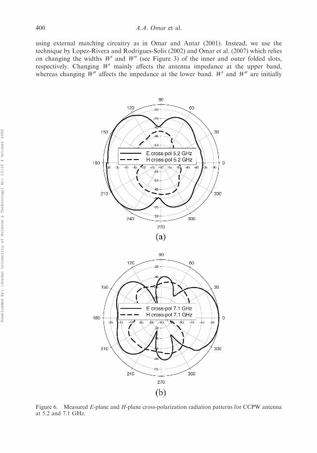
Figure 6. Measured E-plane and H-plane cross-polarization radiation patterns for CCPW antennaat 5.2 and 7.1 GHz.
400 A.A. Omar et al.
Downloaded By: [Jordan University of Science & Technology] At: 13:16 4 October 2009

chosen to be 0.15 mm and then the structure is simulated using the finite element simulatorHFSS (HFSS Software; Ansoft Corporation, USA (www.ansoft.com)). The simulationshowed a poor impedance match between the antenna and the CPW feed line. Following asimilar procedure as explained by Omar et al. (2007), W0 and W00 are changed a few timesuntil a better match is obtained. The resultant widths areW0 ¼ 0.35 mm andW00 ¼ 1.36 mmyielding a return loss of 22 dB and 32 dB, respectively (see Figure 4).
Figure 7. Microphotograph of the CCPS-fed slot antenna illustrating CCPS feed line and SMAconnector.
Figure 8. Surface view of the CCPS-fed slot antenna showing detailed dimensions. (W ¼ 5 mm,S ¼ 0.2 mm, S0 ¼ 2 mm, W0 ¼ 5 mm).
International Journal of Electronics 401
Downloaded By: [Jordan University of Science & Technology] At: 13:16 4 October 2009
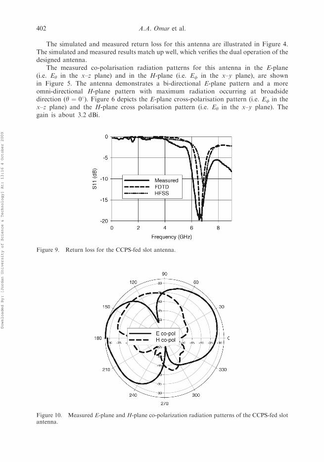
The simulated and measured return loss for this antenna are illustrated in Figure 4.The simulated and measured results match up well, which verifies the dual operation of thedesigned antenna.
The measured co-polarisation radiation patterns for this antenna in the E-plane(i.e. Ey in the x–z plane) and in the H-plane (i.e. Ef in the x–y plane), are shownin Figure 5. The antenna demonstrates a bi-directional E-plane pattern and a moreomni-directional H-plane pattern with maximum radiation occurring at broadsidedirection (y ¼ 08). Figure 6 depicts the E-plane cross-polarisation pattern (i.e. Ef in thex–z plane) and the H-plane cross polarisation pattern (i.e. Ey in the x–y plane). Thegain is about 3.2 dBi.
Figure 9. Return loss for the CCPS-fed slot antenna.
Figure 10. Measured E-plane and H-plane co-polarization radiation patterns of the CCPS-fed slotantenna.
402 A.A. Omar et al.
Downloaded By: [Jordan University of Science & Technology] At: 13:16 4 October 2009
4. Cylindrical CPS-fed slot antenna (CCPS)
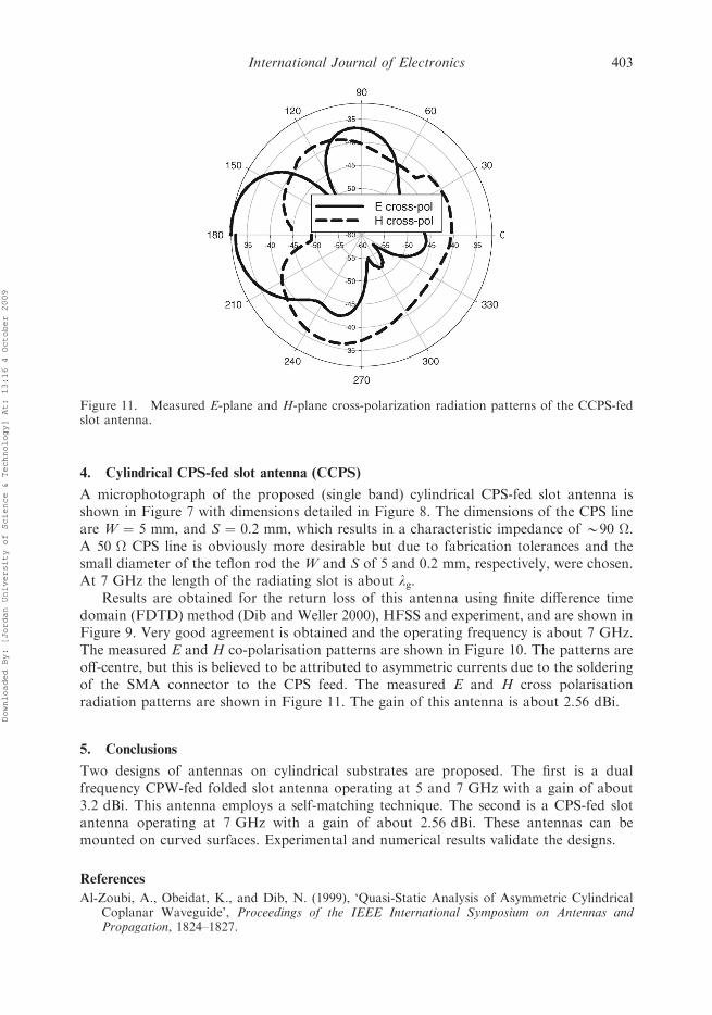
A microphotograph of the proposed (single band) cylindrical CPS-fed slot antenna isshown in Figure 7 with dimensions detailed in Figure 8. The dimensions of the CPS lineare W ¼ 5 mm, and S ¼ 0.2 mm, which results in a characteristic impedance of *90 W.A 50 W CPS line is obviously more desirable but due to fabrication tolerances and thesmall diameter of the teflon rod the W and S of 5 and 0.2 mm, respectively, were chosen.At 7 GHz the length of the radiating slot is about lg.
Results are obtained for the return loss of this antenna using finite difference timedomain (FDTD) method (Dib and Weller 2000), HFSS and experiment, and are shown inFigure 9. Very good agreement is obtained and the operating frequency is about 7 GHz.The measured E and H co-polarisation patterns are shown in Figure 10. The patterns areoff-centre, but this is believed to be attributed to asymmetric currents due to the solderingof the SMA connector to the CPS feed. The measured E and H cross polarisationradiation patterns are shown in Figure 11. The gain of this antenna is about 2.56 dBi.
5. Conclusions
Two designs of antennas on cylindrical substrates are proposed. The first is a dualfrequency CPW-fed folded slot antenna operating at 5 and 7 GHz with a gain of about3.2 dBi. This antenna employs a self-matching technique. The second is a CPS-fed slotantenna operating at 7 GHz with a gain of about 2.56 dBi. These antennas can bemounted on curved surfaces. Experimental and numerical results validate the designs.
References
Al-Zoubi, A., Obeidat, K., and Dib, N. (1999), ‘Quasi-Static Analysis of Asymmetric CylindricalCoplanar Waveguide’, Proceedings of the IEEE International Symposium on Antennas andPropagation, 1824–1827.
Figure 11. Measured E-plane and H-plane cross-polarization radiation patterns of the CCPS-fedslot antenna.
International Journal of Electronics 403
Downloaded By: [Jordan University of Science & Technology] At: 13:16 4 October 2009
Belguessoum, A., and Delisle, G.Y. (2005), ‘A Novel Dual Frequency Operation of CPW CoupledPatch Antenna’, Proceedings of the IEEE International Symposium on Antennas and Propagation,446–449.
Dib, N., and Weller, T. (2000), ‘Finite Difference Time Domain (FDTD) Analysis of CylindricalCoplanar Waveguide (CCPW) Circuits’, International Journal of Electronics, 87, 1083–1094.
Dib, N., Weller, T., Scardelletti, M., and Imparto, M. (1999), ‘Analysis of Cylindrical TransmissionLines with the Finite-Difference Time Domain Method’, IEEE Transactions on MicrowaveTheory Techniques, 47, 509–512.
Hettak, K., Delisle, G.Y., and Stubbs, M.G. (2003), ‘A Novel CPW Coupled Patch AntennaTopology for Dual Band Operation’, Proceedings of the IEEE International Symposium onAntennas and Propagation, 162–166.
Hong, W., Li, S.P., Lin, Y.D., and Kitazawa, T. (2006), ‘Design of Cylindrical Microstrip Leaky-Wave Antenna by the Leaky Mode S-Parameter Extraction Technique’, Acta Press Journal onAntennas, Radar, and Wave Propagation, 511–517.
Hoorfar, A., Gupta, K.C., and Chang, D.C. (2007), ‘Effects of Cylindrical Curvature on Radiationfrom a Microstrip Antenna with a Thick Cover Layer’, Microwave and Optical TechnologyLetters, 6, 762–766.
Hsin-Cheng, S., and Kin-Lu, W. (1996), ‘Dispersion Characteristics of Coplanar Waveguide on acylindrical Substrate’, Proceedings of the IEEE International Symposium on Antennas andPropagation, 2230–2233.
Jain-Ming, J., Berrie, J., Kipp, R., and Lee, S. (1997), ‘Calculation of Radiation Patterns ofMicrostrip Antennas on Cylindrical Bodies of Arbitrary Cross Section’, IEEE Transactions onAntennas and Propagation, 45, 126–132.
Keskilammi, M., and Kivikoski, M. (2003), ‘Cylindrical Patch Antenna Array forRFID Applications’, Proceedings of International ITG-Conference on Antennas INICA, 123–126.
Kim, B., Nikolaou, S., Ponchak, G.E., Kim, Y.S., Papapolymerous, J., and Tentzeris, M.M. (2006),‘A Curvature CPW-Fed Ultra-Wideband Monopole Antenna on Liquid Crystal PolymerSubstrate using Flexible Characteristic’, Proceedings of the IEEE International Symposium onAntennas and Propagation, 1667–1670.
Lieh-Chuan, L., Lin, Y.D., and Kitazawa, T. (2007), ‘Propagation Characteristics of LeakyCoplanar Waveguides on Cylindrical Substrates’, Proceedings of the Asia-Pacific MicrowaveConference, 1–3.
Lin-Lu, W., and Shyh-Yeong, K. (1993), ‘Cylindrical-Rectangular Microstrip Patch Antenna forCircular Polarization’, IEEE Transactions on Antennas and Propagation, 41, 246–249.
Liu, W.C., and Wu, C.M. (2004), ‘Broadband Dual-Frequency CPW-Fed Planar MonopoleAntenna with Rectangular Notch’, Electronics Letters, 642–643.
Lopez-Rivera, N., and Rodrigues-Solis, R. (2002), ‘Impedance Matching Technique for MicrowaveFolded Slot Antennas’, Proceedings of the IEEE International Symposium on Antennas andPropagation, 450–453.
Nakatani, A., and Alexopoulos, N. (1986), ‘Modeling Microstrip Circuits and Microstrip Antennason Cylindrical Substrates’, Proceedings of the IEEE International Symposium on Antennas andPropagation, 439–442.
Omar, A., and Antar, Y.M.M. (2001), ‘Design of a Dual-Band Coplanar Waveguide-fed SlotAntenna with Wide Frequency Separation’, International Journal of Electronics, 88, 1247–1255.
Omar, A.A. (2001), ‘Spectral Domain Analysis of 2-D Cylindrical Transmission Lines composed ofISO/anisotropic Substrates’, Proceedings of the IEEE International Symposium on Antennas andPropagation, 662–665.
Omar, A.A., Scardelletti, M.C., Hejaze, Z.M., and Dib, N. (2007), ‘Design and Measurement of SelfMatched Dual-Frequency Coplanar Waveguide-Fed Slot Antennas’, IEEE Transactions onAntennas and Propagation, 55, 223–226.
Scardelletti, M.C., Dib, N., Weller, T., Culver, J., and King, B. (2005), ‘Coplanar Waveguide-FedSlot Antennas on a Circular Cylindrical Substrate’, International Journal of Electronics andCommunications, 59, 25–30.
Silva, F.D.C., Fonseca, S.B.D.A., Soares, A.J.M., and Giarola, A.J. (1991), ‘Microstrip Antenna Ona Circular Substrate with a Dielectric Cover’, Proceedings of the IEEE International Symposiumon Antennas and Propagation, 24–28.
404 A.A. Omar et al.
Downloaded By: [Jordan University of Science & Technology] At: 13:16 4 October 2009

Surjati, I., Rahardjo, E.T., and Hartano, D. (2006), ‘Increasing Bandwidth of Dual FrequencyTriangular Microstrip Antenna Fed By Coplanar Waveguide’, Aisa Pacific Conference onCommunications APCC, 1–4.
Tilley, K., Wu, X.D., and Chang, K. (1994), ‘Coplanar Waveguide Fed Coplanar Strip DipoleAntenna’, Electronics Letters, 30, 176–177.
US patent 7158089. (2006), ‘Compact Antennas for Ultra Wide Band Applications’.Vandenbosch, G., Beyne, E., Brebels, S., and Soliman, E.A. (1998), ‘Dual frequency Wide Band
Cusp Antennas Fed by Coplanar Waveguide’, 28th European Microwave Conference, 2, 7–11.Vecchi, G., Bertuch, T., and Orefice, M. (1997), ‘Spectral Domain Analysis of Printed Antennas of
General Shape on Cylindrical Substrates’, Proceedings of the IEEE International Symposium onAntennas and Propagation, 1496–1499.
Wang, S., Zhu, Q., Yun, X., and Xu, S. (2007), ‘Design of Cylindrical Conformal Millimeter-WaveMicrostrip Antennas with Broad Beamwidth’, International Journal of Infrared and MillimeterWaves, 28, 465–171.
Wong, K.L. (1999), Design of Nonplanar Microstrip Antennas and Transmission Lines, Chapter 8,New York: Wiley.
International Journal of Electronics 405
Downloaded By: [Jordan University of Science & Technology] At: 13:16 4 October 2009