Embed Size (px)
Citation preview
Plowing for Controlled Steep Crater Descents
Jason Ziglar, David Kohanbash, David Wettergreen, and William WhittakerCarnegie Mellon University
[email protected], [email protected]
Abstract
Controlling slip is crucial to reliable descent of steep un-consolidated slopes such as those found in lunar craters. Theability to enter these craters provides opportunities to explorepotential in-situ resources, such as water ice. We presenta rover prototype with a novel, actuated, omni-directionalplowing device and control method for maneuvering on steepslopes. Data from field experiments show reliable control dur-ing descent on loose sand slopes up to 40◦, with twenty-foldreduction in downhill slip and a threefold reduction in slipduring point turns. In particular, the data indicates that plow-ing eliminates slip caused by shear failure created in angle-of-repose material.
1. IntroductionDiscovering water ice and other important volatiles on the
lunar surface drives attempts to explore the interior of lunarcraters. Volatile trapping craters may range in size from afew tens of meters to tens of kilometers in diameter. Plansfor extended human presence on the lunar surface benefit sig-nificantly from in-situ resource utilization [14]. With evidencethat cold traps located in craters at the lunar poles potentiallycontain water ice [1, 8, 5, 20] controlled descent of craterslopes is a keystone to exploring these resources.
Models for lunar craters estimate unconsolidated regolithslopes with a 30 - 40◦ angle-of-repose [6, 7]. These slopes ex-hibit fluid-like flows of soil, resulting in an uncontrolled “surf-ing” descent. Theory suggests that for loose, granular soil,strength lies under the surface, not on, the surface [18, 21]. Inorder to explore rover technologies for this regime of locomo-tion, Icebreaker, a prototype rover is presented. The primaryobjective of this rover is to explore and develop concepts oflocomotion for crater descent. Research pushes technologiesand configuration requirements for planetary rovers intendedto descend steep crater walls. The primary innovation is theuse of plowing to control descent.
2. Rover DesignGoals of steep crater navigation come from a mission pro-
posal to send a small, low cost rover as a secondary payloadopportunity [3]. The mission framework called for exploration
of lunar craters with little available space; a compact, capa-ble rover could fit the requirements, but costs would require arover capable of landing outside a crater to descend inwards.These limitations drive the design towards the current form.
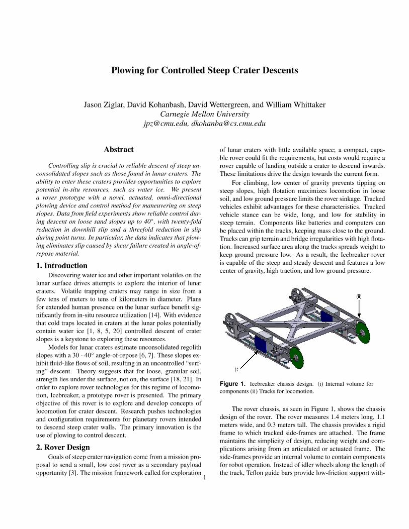
For climbing, low center of gravity prevents tipping onsteep slopes, high flotation maximizes locomotion in loosesoil, and low ground pressure limits the rover sinkage. Trackedvehicles exhibit advantages for these characteristics. Trackedvehicle stance can be wide, long, and low for stability insteep terrain. Components like batteries and computers canbe placed within the tracks, keeping mass close to the ground.Tracks can grip terrain and bridge irregularities with high flota-tion. Increased surface area along the tracks spreads weight tokeep ground pressure low. As a result, the Icebreaker roveris capable of the steep and steady descent and features a lowcenter of gravity, high traction, and low ground pressure.
Figure 1. Icebreaker chassis design. (i) Internal volume forcomponents (ii) Tracks for locomotion.
The rover chassis, as seen in Figure 1, shows the chassisdesign of the rover. The rover measures 1.4 meters long, 1.1meters wide, and 0.3 meters tall. The chassis provides a rigidframe to which tracked side-frames are attached. The framemaintains the simplicity of design, reducing weight and com-plications arising from an articulated or actuated frame. Theside-frames provide an internal volume to contain componentsfor robot operation. Instead of idler wheels along the length ofthe track, Teflon guide bars provide low-friction support with-
1
out using any significant volume. The chassis provides a lowcenter of gravity to prevent tipping on steep slopes, and a wide,long, and low stance for stability in deep terrain. The tracksprovide locomotive force with high flotation, low ground pres-sure, and increased surface area. These characteristics allowthe rover to grip terrain, bridge surface irregularities, and limitrover sinkage.
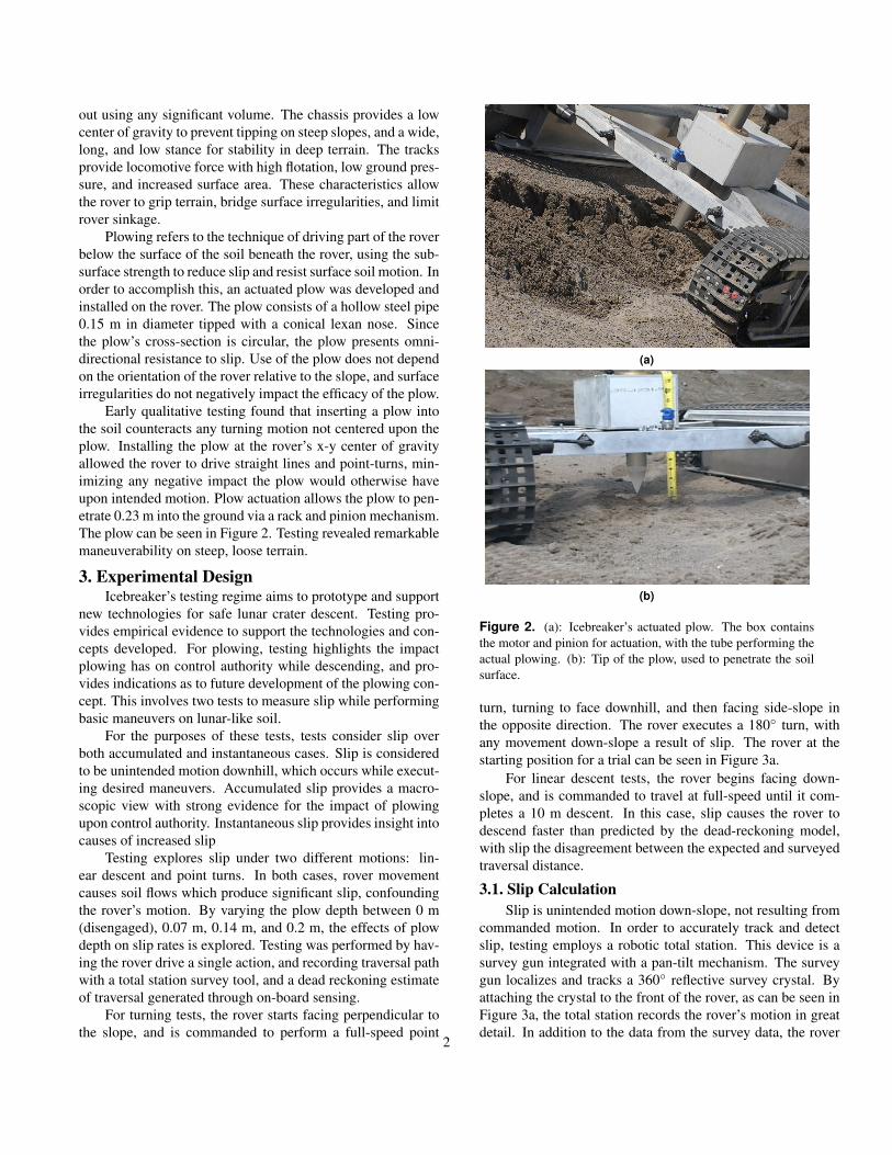
Plowing refers to the technique of driving part of the roverbelow the surface of the soil beneath the rover, using the sub-surface strength to reduce slip and resist surface soil motion. Inorder to accomplish this, an actuated plow was developed andinstalled on the rover. The plow consists of a hollow steel pipe0.15 m in diameter tipped with a conical lexan nose. Sincethe plow’s cross-section is circular, the plow presents omni-directional resistance to slip. Use of the plow does not dependon the orientation of the rover relative to the slope, and surfaceirregularities do not negatively impact the efficacy of the plow.
Early qualitative testing found that inserting a plow intothe soil counteracts any turning motion not centered upon theplow. Installing the plow at the rover’s x-y center of gravityallowed the rover to drive straight lines and point-turns, min-imizing any negative impact the plow would otherwise haveupon intended motion. Plow actuation allows the plow to pen-etrate 0.23 m into the ground via a rack and pinion mechanism.The plow can be seen in Figure 2. Testing revealed remarkablemaneuverability on steep, loose terrain.
3. Experimental DesignIcebreaker’s testing regime aims to prototype and support
new technologies for safe lunar crater descent. Testing pro-vides empirical evidence to support the technologies and con-cepts developed. For plowing, testing highlights the impactplowing has on control authority while descending, and pro-vides indications as to future development of the plowing con-cept. This involves two tests to measure slip while performingbasic maneuvers on lunar-like soil.
For the purposes of these tests, tests consider slip overboth accumulated and instantaneous cases. Slip is consideredto be unintended motion downhill, which occurs while execut-ing desired maneuvers. Accumulated slip provides a macro-scopic view with strong evidence for the impact of plowingupon control authority. Instantaneous slip provides insight intocauses of increased slip
Testing explores slip under two different motions: lin-ear descent and point turns. In both cases, rover movementcauses soil flows which produce significant slip, confoundingthe rover’s motion. By varying the plow depth between 0 m(disengaged), 0.07 m, 0.14 m, and 0.2 m, the effects of plowdepth on slip rates is explored. Testing was performed by hav-ing the rover drive a single action, and recording traversal pathwith a total station survey tool, and a dead reckoning estimateof traversal generated through on-board sensing.
For turning tests, the rover starts facing perpendicular tothe slope, and is commanded to perform a full-speed point
(a)
(b)
Figure 2. (a): Icebreaker’s actuated plow. The box containsthe motor and pinion for actuation, with the tube performing theactual plowing. (b): Tip of the plow, used to penetrate the soilsurface.
turn, turning to face downhill, and then facing side-slope inthe opposite direction. The rover executes a 180◦ turn, withany movement down-slope a result of slip. The rover at thestarting position for a trial can be seen in Figure 3a.
For linear descent tests, the rover begins facing down-slope, and is commanded to travel at full-speed until it com-pletes a 10 m descent. In this case, slip causes the rover todescend faster than predicted by the dead-reckoning model,with slip the disagreement between the expected and surveyedtraversal distance.
3.1. Slip CalculationSlip is unintended motion down-slope, not resulting from
commanded motion. In order to accurately track and detectslip, testing employs a robotic total station. This device is asurvey gun integrated with a pan-tilt mechanism. The surveygun localizes and tracks a 360◦ reflective survey crystal. Byattaching the crystal to the front of the rover, as can be seen inFigure 3a, the total station records the rover’s motion in greatdetail. In addition to the data from the survey data, the rover
2

(a) (b)
(c) (d) (e)
Figure 3. Sequence of rover orientations, showing a single trial of the turning test. For reference, the orange crystal is mounted towards thefront of the rover.
internally records roll, pitch, yaw-rate, and velocity commandsfor a simple internal dead-reckoning model.
With this data, slip calculations for turning tests simplifyto a trivial calculation. Since the rover performs a point turnfor each trial, no down-slope translation can occur in the idealcase. Thus, any down-slope movement of the rover measuredby the total station turns out to be slip by definition. In thiscase, the internal dead-reckoning model is unnecessary. Accu-mulating all the down-slope translation recorded by the totalstation is the only step required to calculate slip.
For linear descent, slip calculations require only slightlymore calculation. Since the rover descends along the max-imum gradient, and performs only a straight translation, themotion model can be simplified to a single point, moving atvrover = vlefttrack+vrighttrack
2 . By propagating the rover for-ward with this velocity, and comparing this to the surveyeddistance traveled, slip is calculated using a minimal amount ofsensor data.
4. ResultsIn-place turning was tested with 0 m, 0.07 m, and 0.2 m
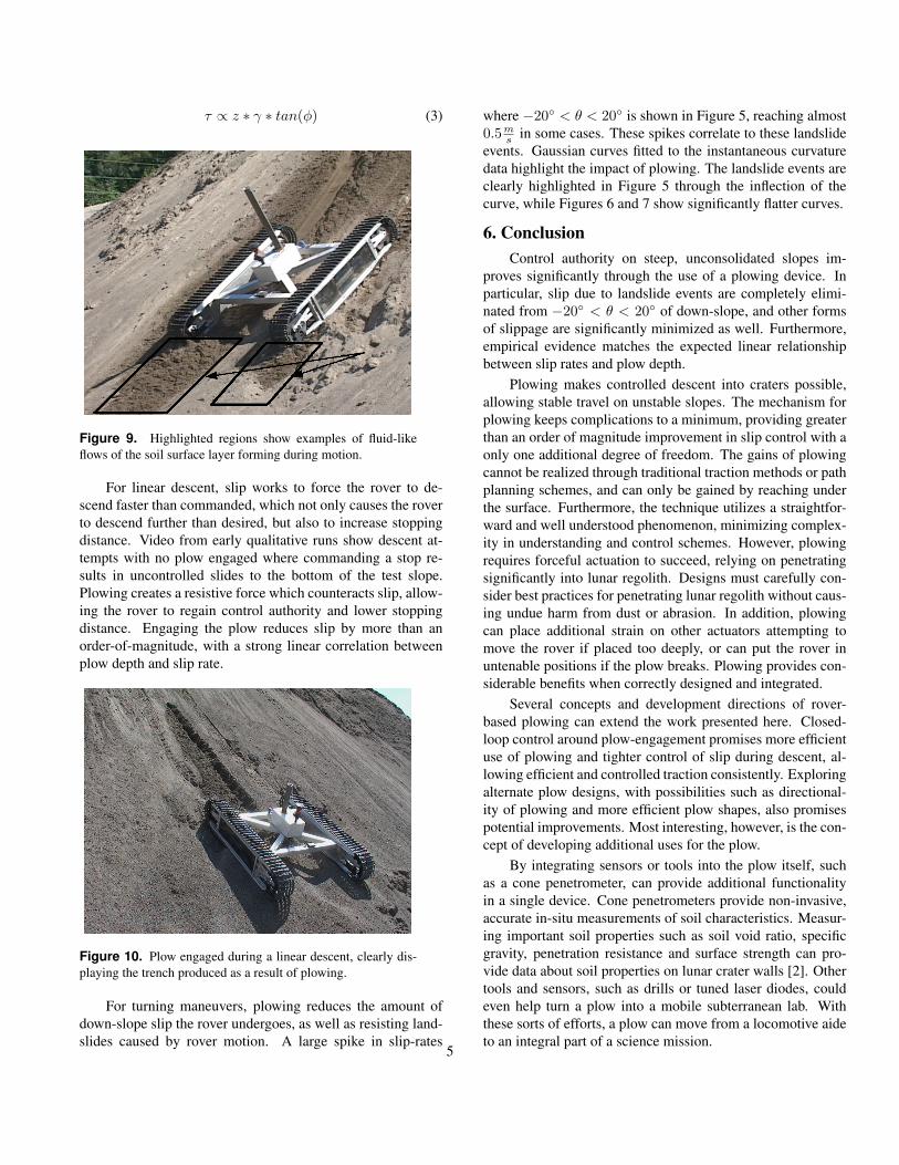
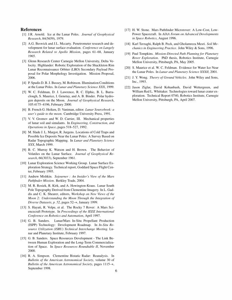
plow depths. Figure 4 shows the accumulated slip for eachtrial, with the plot of a linear regression across all trials (r2 =0.94.) Comparing mean accumulated slip between 0 m and0.2 m plow depths, results show a reduction in slip by a factorof 3.2. Figures 5, 6, and 7 show the calculated slip-rates as afunction of yaw at each individual plow depth.
For linear descent, at least three trials were performed
Figure 4. Accumulated slip during turning maneuvers with var-ious plow deployments.
with the plow depth set to 0 m, 0.07 m, 0.14 m, and 0.2 m.Figure 8 records accumulated slip for each trial, with the plotof a linear regression over all trial data (r2 = 0.89.) Compar-ing mean accumulated slip at 0 m and 0.2 m plow depths, theplow reduces slip by a factor of 19.6 in linear descent. Resultsof both tests are summarized in Table 1.
5. DiscussionPlowing significantly reduces slip and improves control
authority during descent on steep, unconsolidated slopes. Sub-surface strength comes from Control authority is the ability of
3
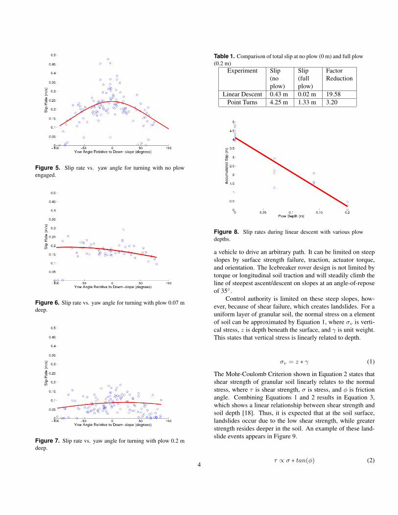
Figure 5. Slip rate vs. yaw angle for turning with no plowengaged.
Figure 6. Slip rate vs. yaw angle for turning with plow 0.07 mdeep.
Figure 7. Slip rate vs. yaw angle for turning with plow 0.2 mdeep.
Table 1. Comparison of total slip at no plow (0 m) and full plow(0.2 m)
Experiment Slip(noplow)
Slip(fullplow)
FactorReduction
Linear Descent 0.43 m 0.02 m 19.58Point Turns 4.25 m 1.33 m 3.20
Figure 8. Slip rates during linear descent with various plowdepths.
a vehicle to drive an arbitrary path. It can be limited on steepslopes by surface strength failure, traction, actuator torque,and orientation. The Icebreaker rover design is not limited bytorque or longitudinal soil traction and will steadily climb theline of steepest ascent/descent on slopes at an angle-of-reposeof 35◦.
Control authority is limited on these steep slopes, how-ever, because of shear failure, which creates landslides. For auniform layer of granular soil, the normal stress on a elementof soil can be approximated by Equation 1, where σv is verti-cal stress, z is depth beneath the surface, and γ is unit weight.This states that vertical stress is linearly related to depth.
σv = z ∗ γ (1)
The Mohr-Coulomb Criterion shown in Equation 2 states thatshear strength of granular soil linearly relates to the normalstress, where τ is shear strength, σ is stress, and φ is frictionangle. Combining Equations 1 and 2 results in Equation 3,which shows a linear relationship between shear strength andsoil depth [18]. Thus, it is expected that at the soil surface,landslides occur due to the low shear strength, while greaterstrength resides deeper in the soil. An example of these land-slide events appears in Figure 9.
τ ∝ σ ∗ tan(φ) (2)4
τ ∝ z ∗ γ ∗ tan(φ) (3)
Figure 9. Highlighted regions show examples of fluid-likeflows of the soil surface layer forming during motion.
For linear descent, slip works to force the rover to de-scend faster than commanded, which not only causes the roverto descend further than desired, but also to increase stoppingdistance. Video from early qualitative runs show descent at-tempts with no plow engaged where commanding a stop re-sults in uncontrolled slides to the bottom of the test slope.Plowing creates a resistive force which counteracts slip, allow-ing the rover to regain control authority and lower stoppingdistance. Engaging the plow reduces slip by more than anorder-of-magnitude, with a strong linear correlation betweenplow depth and slip rate.
Figure 10. Plow engaged during a linear descent, clearly dis-playing the trench produced as a result of plowing.
For turning maneuvers, plowing reduces the amount ofdown-slope slip the rover undergoes, as well as resisting land-slides caused by rover motion. A large spike in slip-rates
where −20◦ < θ < 20◦ is shown in Figure 5, reaching almost0.5m
s in some cases. These spikes correlate to these landslideevents. Gaussian curves fitted to the instantaneous curvaturedata highlight the impact of plowing. The landslide events areclearly highlighted in Figure 5 through the inflection of thecurve, while Figures 6 and 7 show significantly flatter curves.
6. ConclusionControl authority on steep, unconsolidated slopes im-
proves significantly through the use of a plowing device. Inparticular, slip due to landslide events are completely elimi-nated from −20◦ < θ < 20◦ of down-slope, and other formsof slippage are significantly minimized as well. Furthermore,empirical evidence matches the expected linear relationshipbetween slip rates and plow depth.
Plowing makes controlled descent into craters possible,allowing stable travel on unstable slopes. The mechanism forplowing keeps complications to a minimum, providing greaterthan an order of magnitude improvement in slip control with aonly one additional degree of freedom. The gains of plowingcannot be realized through traditional traction methods or pathplanning schemes, and can only be gained by reaching underthe surface. Furthermore, the technique utilizes a straightfor-ward and well understood phenomenon, minimizing complex-ity in understanding and control schemes. However, plowingrequires forceful actuation to succeed, relying on penetratingsignificantly into lunar regolith. Designs must carefully con-sider best practices for penetrating lunar regolith without caus-ing undue harm from dust or abrasion. In addition, plowingcan place additional strain on other actuators attempting tomove the rover if placed too deeply, or can put the rover inuntenable positions if the plow breaks. Plowing provides con-siderable benefits when correctly designed and integrated.
Several concepts and development directions of rover-based plowing can extend the work presented here. Closed-loop control around plow-engagement promises more efficientuse of plowing and tighter control of slip during descent, al-lowing efficient and controlled traction consistently. Exploringalternate plow designs, with possibilities such as directional-ity of plowing and more efficient plow shapes, also promisespotential improvements. Most interesting, however, is the con-cept of developing additional uses for the plow.
By integrating sensors or tools into the plow itself, suchas a cone penetrometer, can provide additional functionalityin a single device. Cone penetrometers provide non-invasive,accurate in-situ measurements of soil characteristics. Measur-ing important soil properties such as soil void ratio, specificgravity, penetration resistance and surface strength can pro-vide data about soil properties on lunar crater walls [2]. Othertools and sensors, such as drills or tuned laser diodes, couldeven help turn a plow into a mobile subterranean lab. Withthese sorts of efforts, a plow can move from a locomotive aideto an integral part of a science mission.
5
References[1] J.R. Arnold. Ice at the Lunar Poles. Journal of Geophysical
Research, 84(5659), 1979.[2] A.G. Beswick and J.L. Mccarty. Penetrometer research and de-
velopment for lunar surface evaluation. Conference on LangelyResearch Related to Apollo Mission, pages 61–68, January1965.
[3] Glenn Research Center Carnegie Mellon University, Delta Ve-locity. Highlander: Robotic Exploration of the Shackleton RimLunar Reconnaissance Orbiter (LRO) Secondary Payload Pro-posal for Polar Morphology Investigation. Mission Proposal,2006.
[4] P. Spudis D. B. J. Bussey, M. Robinson. Illumination Conditionsat the Lunar Poles. In Lunar and Planetary Science XXX, 1999.
[5] W. C. Feldman, D. J. Lawrence, R. C. Elphic, B. L. Barra-clough, S. Maurice, I. Genetay, and A. B. Binder. Polar hydro-gen deposits on the Moon. Journal of Geophysical Research,105:4175–4196, February 2000.
[6] B. French G. Heiken, D. Vaniman, editor. Lunar Sourcebook: auser’s guide to the moon. Cambridge University Press, 1991.
[7] V. V. Gromov and W. D. Carrier, III. Mechanical propertiesof lunar soil and simulants. In Engineering, Construction, andOperations in Space, pages 518–527, 1992.
[8] M. Slade J. L. Margot, R. Jurgens. Locations of Cold Traps andPossible Ice Deposits Near the Lunar Poles: A Survey Based onRadar Topographic Mapping. In Lunar and Planetary ScienceXXX, March 1999.
[9] B. C. Murray K. Watson and H. Brown. The Behavior ofVolatiles on the Lunar Surface. Journal of Geophysical Re-search, 66(3033), September 1961.
[10] Lunar Exploration Science Working Group. Lunar Surface Ex-ploration Strategy. Technical report, Goddard Space Flight Cen-ter, February 1995.
[11] Andrew Mishkin. Sojourner : An Insider’s View of the MarsPathfinder Mission. Berkley Trade, 2004.
[12] M. R. Rosiek, R. Kirk, and A. Howington-Kraus. Lunar SouthPole Topography Derived from Clementine Imagery. In L. Gad-dis and C. K. Shearer, editors, Workshop on New Views of theMoon 2: Understanding the Moon Through the Integration ofDiverse Datasets, p. 52, pages 52–+, January 1999.
[13] S. Hayati, R. Volpe, et al. The Rocky 7 Rover: A Mars Sci-encecraft Prototype. In Proceedings of the IEEE InternationalConference on Robotics and Automation, April 1997.
[14] G. B. Sanders. Lunar/Mars In-Situ Propellant Production(ISPP) Technology: Development Roadmap. In In-Situ Re-source Utilization (ISRU) Technical Interchange Meeting. Lu-nar and Planetary Institute, February 1997.
[15] G. B. Sanders. Space Resources Development - The Link Be-tween Human Exploration and the Long-Term Commercializa-tion of Space. In Space Resources Roundtable II, November2000.
[16] R. A. Simpson. Clementine Bistatic Radar: Reanalysis. InBulletin of the American Astronomical Society, volume 30 ofBulletin of the American Astronomical Society, pages 1115–+,September 1998.
[17] H. W. Stone. Mars Pathfinder Microrover: A Low-Cost, Low-Power Spacecraft. In AIAA Forum on Advanced Developmentsin Space Robotics, August 1996.
[18] Karl Terzaghi, Ralph B. Peck, and Gholamreza Mesri. Soil Me-chanics in Engineering Practice. John Wiley & Sons, 1996.
[19] Paul Tompkins. Mission-Directed Path Planning for PlanetaryRover Exploration. PhD thesis, Robotics Institute, CarnegieMellon University, Pittsburgh, PA, May 2005.
[20] S. Maurice et al. W. C. Feldman. Evidence for Water Ice Nearthe Lunar Poles. In Lunar and Planetary Science XXXII, 2001.
[21] J. Y. Wong. Theory of Ground Vehicles. John Wiley and Sons,Inc., 1993.
[22] Jason Ziglar, David Kohanbash, David Wettergreen, andWilliam Red L. Whittaker. Technologies toward lunar crater ex-ploration. Technical Report 0740, Robotics Institute, CarnegieMellon University, Pittsburgh, PA, April 2007.
6