Embed Size (px)
Citation preview
Plumbing in Autodesk® Revit® MEP: You’re No Longer Just a Subcategory
Speaker: Kristin Woodard – CADD Microsystems
MP1823
This class is designed to improve design efficiency specifically for the plumbing discipline. In the class, you will learn how to use the pipe routing preferences in Autodesk® Revit® MEP software to your advantage, how to map plumbing connectors for proper flow, and how to track fixture units within systems. We will also show how the basic lookup tables drive the outside diameter (OD) size of your double-line piping, provide tips for the use of sloped piping, and finally, demonstrate how preconfigured families can make rough-in schedules a breeze.
LearningObjectivesAt the end of this class, you will be able to:
Create new Pipe System Types Utilize the 2013 pipe routing preferences Modify look up tables Map Pipe Connectors for proper flow Create Rough – in Schedules Utilize the Fixture Units Create plumbing groups for re-use
AbouttheSpeaker Kristin is an Applications Specialist with CADD Microsystems, an Autodesk Platinum Reseller. She specializes in Revit and Navisworks for the MEP and Construction Industries and has worked with Autodesk products since 1998. She is skilled in Mechanical design, creating Revit family content, and developing innovative solutions to workflow problems. Kristin is also a skilled educator and trainer for the AEC industry who teaches several classes in the Virginia, D.C. and Maryland Areas [email protected]
Plumbing in Autodesk® Revit® MEP: You’re No Longer Just a Subcategory
2
Introduction
Plumbing in Autodesk® Revit® MEP is now a full-fledged discipline within the product. Using the parametric data, systems, and calculations to our advantage we can produce designs with efficiency and accuracy.
PipeSystemTypes
A new addition to the Autodesk® Revit® MEP product is the ability to create custom system types. These systems are based upon the basic system framework that preceded it – system classifications
Definitions:
System Classification – The official classifications for connectors and the system browser. These classifications are limited to:
Hydronic Supply
Hydronic Return
Sanitary
Vent
Domestic Cold Water
Domestic Hot Water
Fire Protection Wet
Fire Protection Dry
Fire Protection Pre-Action
Fire Protection Other
System Type – The customizable systems available to the Autodesk® Revit® MEP user. These classifications are not limited, but must be created using a duplication of the original “out of the box” system types which are tied to the above listed system classifications.
Pipe Type – used for material, connection type and pipe routing preferences. These types are not intended for use to designate systems.
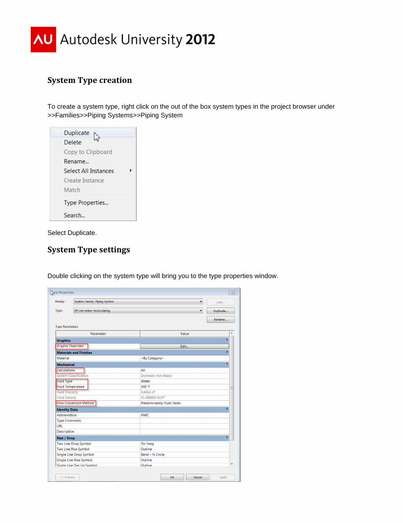
SystemTypecreation
To create a system type, right click on the out of the box system types in the project browser under >>Families>>Piping Systems>>Piping System
Select Duplicate.
SystemTypesettings
Double clicking on the system type will bring you to the type properties window.
Plumbing in Autodesk® Revit® MEP: You’re No Longer Just a Subcategory
4
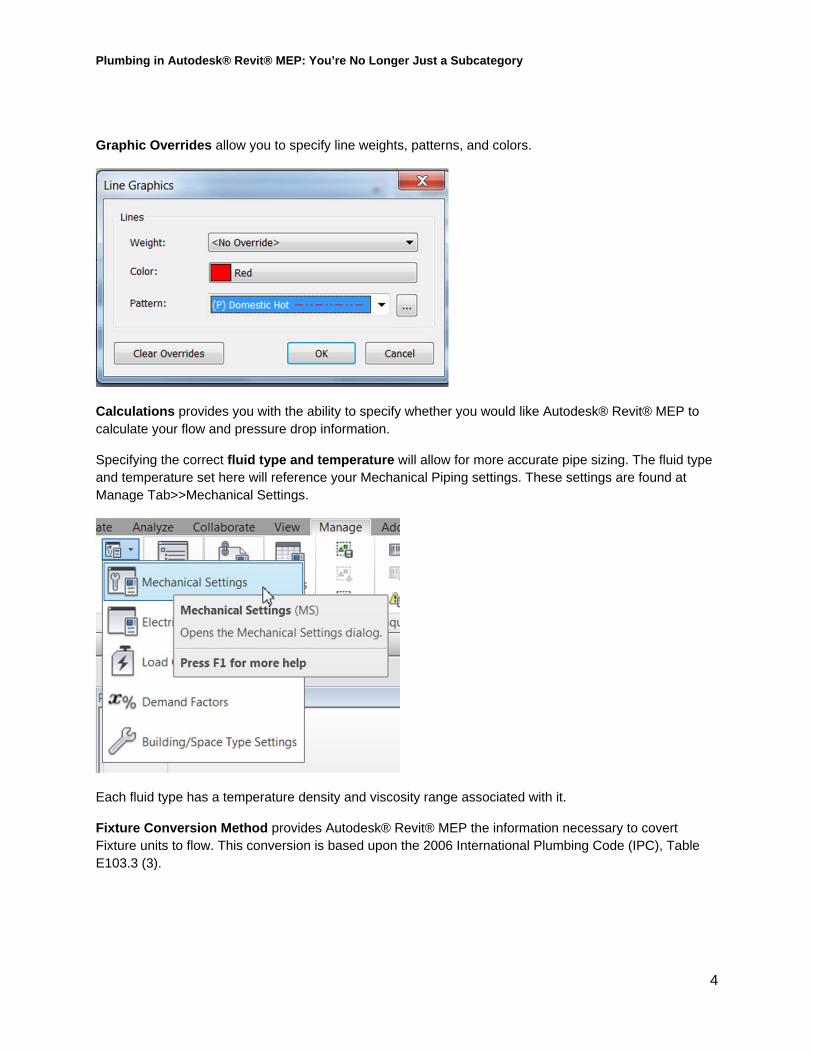
Graphic Overrides allow you to specify line weights, patterns, and colors.
Calculations provides you with the ability to specify whether you would like Autodesk® Revit® MEP to calculate your flow and pressure drop information.
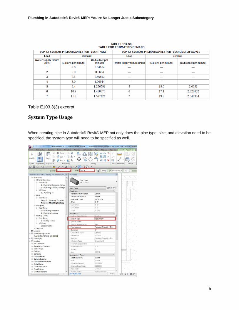
Specifying the correct fluid type and temperature will allow for more accurate pipe sizing. The fluid type and temperature set here will reference your Mechanical Piping settings. These settings are found at Manage Tab>>Mechanical Settings.
Each fluid type has a temperature density and viscosity range associated with it.
Fixture Conversion Method provides Autodesk® Revit® MEP the information necessary to covert Fixture units to flow. This conversion is based upon the 2006 International Plumbing Code (IPC), Table E103.3 (3).
Plumbing in Autodesk® Revit® MEP: You’re No Longer Just a Subcategory
5
Table E103.3(3) excerpt
SystemTypeUsage
When creating pipe in Autodesk® Revit® MEP not only does the pipe type; size; and elevation need to be specified, the system type will need to be specified as well.
Plumbing in Autodesk® Revit® MEP: You’re No Longer Just a Subcategory
6
PipeRoutingPreferences
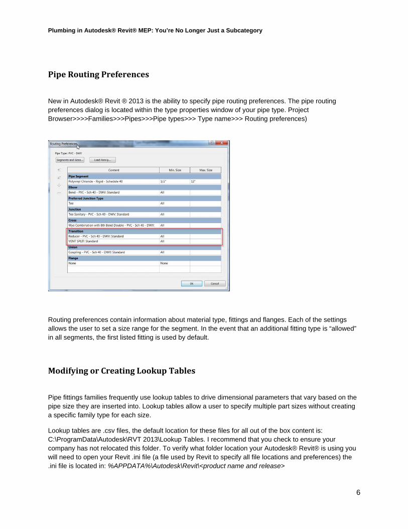
New in Autodesk® Revit ® 2013 is the ability to specify pipe routing preferences. The pipe routing preferences dialog is located within the type properties window of your pipe type. Project Browser>>>>Families>>>Pipes>>>Pipe types>>> Type name>>> Routing preferences)
Routing preferences contain information about material type, fittings and flanges. Each of the settings allows the user to set a size range for the segment. In the event that an additional fitting type is “allowed” in all segments, the first listed fitting is used by default.
ModifyingorCreatingLookupTables
Pipe fittings families frequently use lookup tables to drive dimensional parameters that vary based on the pipe size they are inserted into. Lookup tables allow a user to specify multiple part sizes without creating a specific family type for each size.
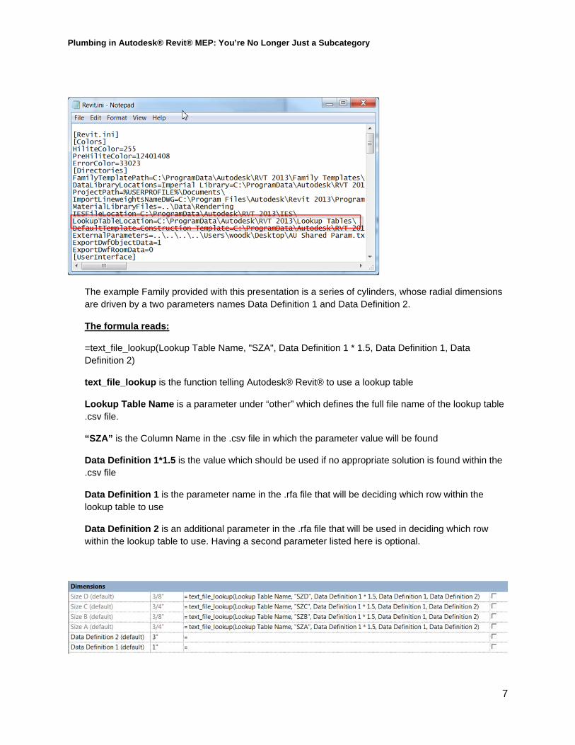
Lookup tables are .csv files, the default location for these files for all out of the box content is: C:\ProgramData\Autodesk\RVT 2013\Lookup Tables. I recommend that you check to ensure your company has not relocated this folder. To verify what folder location your Autodesk® Revit® is using you will need to open your Revit .ini file (a file used by Revit to specify all file locations and preferences) the .ini file is located in: %APPDATA%\Autodesk\Revit\<product name and release>
Plumbing in Autodesk® Revit® MEP: You’re No Longer Just a Subcategory
7
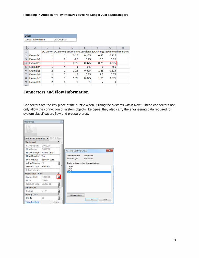
The example Family provided with this presentation is a series of cylinders, whose radial dimensions are driven by a two parameters names Data Definition 1 and Data Definition 2.
The formula reads:
=text_file_lookup(Lookup Table Name, "SZA", Data Definition 1 * 1.5, Data Definition 1, Data Definition 2)
text_file_lookup is the function telling Autodesk® Revit® to use a lookup table
Lookup Table Name is a parameter under “other” which defines the full file name of the lookup table .csv file.
“SZA” is the Column Name in the .csv file in which the parameter value will be found
Data Definition 1*1.5 is the value which should be used if no appropriate solution is found within the .csv file
Data Definition 1 is the parameter name in the .rfa file that will be deciding which row within the lookup table to use
Data Definition 2 is an additional parameter in the .rfa file that will be used in deciding which row within the lookup table to use. Having a second parameter listed here is optional.
Plumbing in Autodesk® Revit® MEP: You’re No Longer Just a Subcategory
8
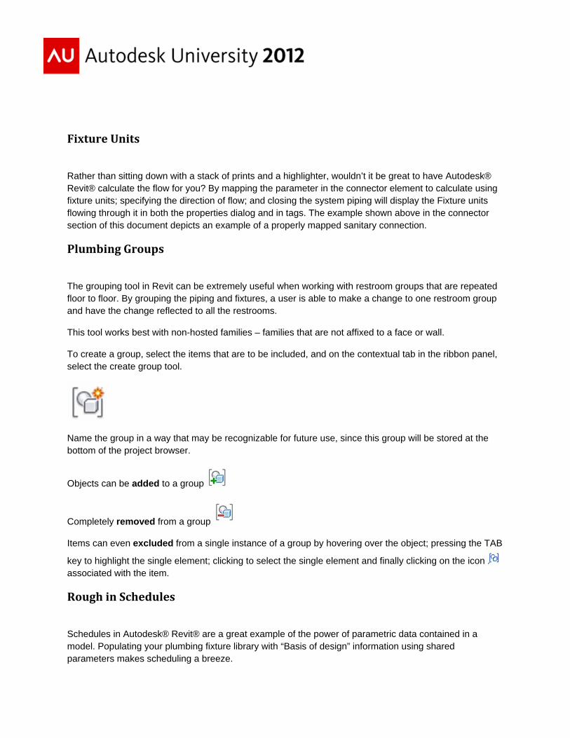
ConnectorsandFlowInformation
Connectors are the key piece of the puzzle when utilizing the systems within Revit. These connectors not only allow the connection of system objects like pipes, they also carry the engineering data required for system classification, flow and pressure drop.
FixtureUnits
Rather than sitting down with a stack of prints and a highlighter, wouldn’t it be great to have Autodesk® Revit® calculate the flow for you? By mapping the parameter in the connector element to calculate using fixture units; specifying the direction of flow; and closing the system piping will display the Fixture units flowing through it in both the properties dialog and in tags. The example shown above in the connector section of this document depicts an example of a properly mapped sanitary connection.
PlumbingGroups
The grouping tool in Revit can be extremely useful when working with restroom groups that are repeated floor to floor. By grouping the piping and fixtures, a user is able to make a change to one restroom group and have the change reflected to all the restrooms.
This tool works best with non-hosted families – families that are not affixed to a face or wall.
To create a group, select the items that are to be included, and on the contextual tab in the ribbon panel, select the create group tool.
Name the group in a way that may be recognizable for future use, since this group will be stored at the bottom of the project browser.
Objects can be added to a group
Completely removed from a group
Items can even excluded from a single instance of a group by hovering over the object; pressing the TAB
key to highlight the single element; clicking to select the single element and finally clicking on the icon associated with the item.
RoughinSchedules
Schedules in Autodesk® Revit® are a great example of the power of parametric data contained in a model. Populating your plumbing fixture library with “Basis of design” information using shared parameters makes scheduling a breeze.
Plumbing in Autodesk® Revit® MEP: You’re No Longer Just a Subcategory
10
Storing the schedules (and possibly your custom details as well) in a separate file keeps your template file size down, allowing only the content necessary for project completion to be placed in your project file.
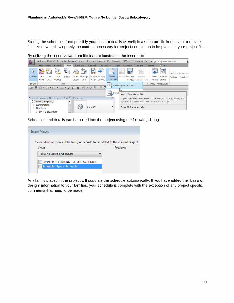
By utilizing the insert views from file feature located on the insert tab:
Schedules and details can be pulled into the project using the following dialog:
Any family placed in the project will populate the schedule automatically. If you have added the “basis of design” information to your families, your schedule is complete with the exception of any project specific comments that need to be made.