Embed Size (px)
Citation preview

CORE
COMPETENCY
UNIT OF COMPETENCY : PREPARE PIPES FOR INSTALLATION
IDENTIFY and SELECT MATERIALS, TOOLS and EQUIPMENT
Types of household water supply pipes
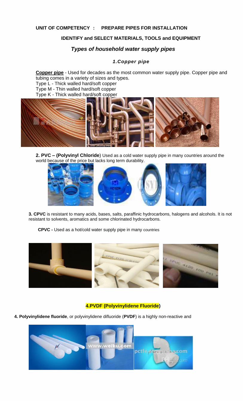
1.Copper pipe
Copper pipe - Used for decades as the most common water supply pipe. Copper pipe and tubing comes in a variety of sizes and types. Type L - Thick walled hard/soft copper Type M - Thin walled hard/soft copper Type K - Thick walled hard/soft copper
2. PVC – (Polyvinyl Chloride) Used as a cold water supply pipe in many countries around the
world because of the price but lacks long term durability.
3. CPVC is resistant to many acids, bases, salts, paraffinic hydrocarbons, halogens and alcohols. It is not resistant to solvents, aromatics and some chlorinated hydrocarbons.
CPVC - Used as a hot/cold water supply pipe in many countries
4.PVDF (Polyvinylidene Fluoride) 4. Polyvinylidene fluoride, or polyvinylidene difluoride (PVDF) is a highly non-reactive and
PE (Polyethylene)
Polyethylene has been successfully used for the safe conveyance of gases for many years.
Plastic water pipes and fittings(PE,PP and blue pipes)
High-density polyethylene (HDPE) or polyethylene high-density (PEHD)
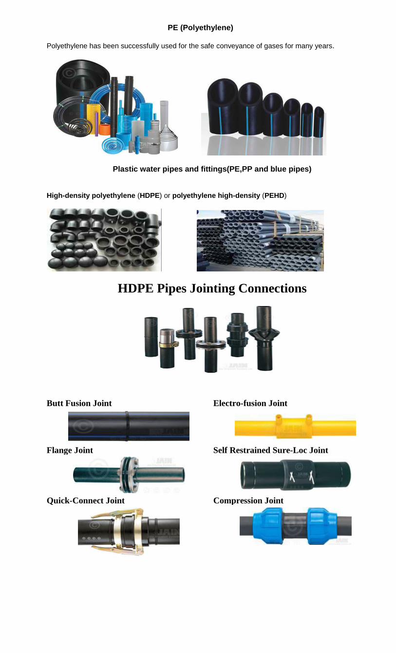
HDPE Pipes Jointing Connections
Butt Fusion Joint Electro-fusion Joint
Flange Joint Self Restrained Sure-Loc Joint
Quick-Connect Joint Compression Joint
ABS (Acrylonitrile Butadiene Styrene)
ABS is derived from acrylonitrile, butadiene, and styrene. Acrylonitrile is a synthetic monomer produced
from propylene and ammonia; butadiene is a petroleum hydrocarbon obtained from the C4 fraction
of steam cracking; styrene monomer is made by dehydrogenation ofethyl benzene — a hydrocarbon
obtained in the reaction of ethylene and benzene.
PP (Polypropylene) Polyprophylene pipe is used in many industrial settings due to its chemical and thermal resistance, affordability, and
cost
Galvanized Iron pipe
n
Steel
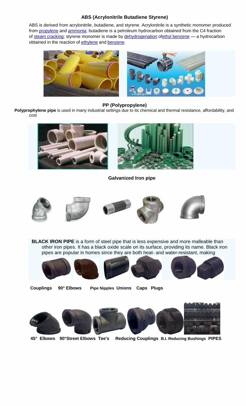
BLACK IRON PIPE is a form of steel pipe that is less expensive and more malleable than other iron pipes. It has a black oxide scale on its surface, providing its name. Black iron pipes are popular in homes since they are both heat- and water-resistant, making
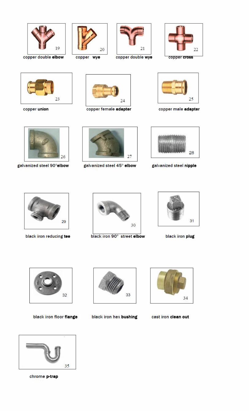
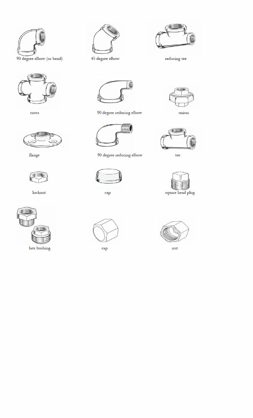
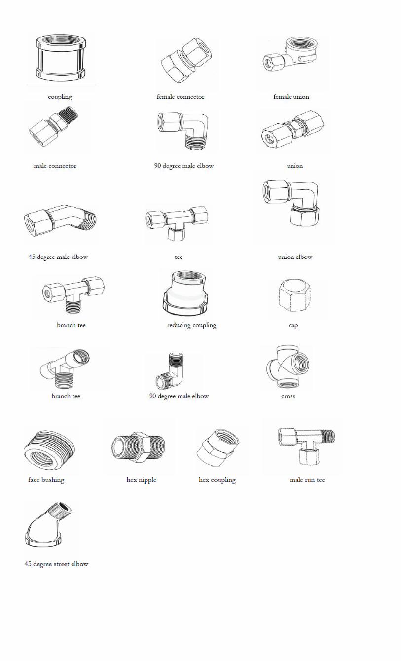
Couplings 90° Elbows Pipe Nipples Unions Caps Plugs
45° Elbows 90°Street Elbows Tee's Reducing Couplings B.I. Reducing Bushings PIPES
Types of household drainage pipes
1. Cast iron pipe The cast iron pipe is heavy, but it is very durable and very common. Compared to plastic, the cast iron pipe will be much quieter, and a lot more durable, and will better withstand chemical and mechanical pipe -cleaning equipment.
UPVC (Unplasticized Polyvinyl Chloride) and CPVC (Post Chlorinated Polyvinyl Chloride) UPVC has excellent chemical resistance across its operating temperature range, with a broad band of operating pressures. Due to its long-term strength characteristics, high stiffness and cost effectiveness, UPVC systems account for a large proportion of plastic piping installations.
PVC PIPES
PVC pipe is manufactured by extrusion in a variety of sizes and dimensions and generally sold in 10' and 20' lengths. PVC pipe is available in both solid wall or cellular core construction. Cellular core construction involves the simultaneous extrusion of at least three layers of material into the pipe wall: a solid outer layer, a cellular core intermediate layer, and a solid inner layer. PVC pipe is made to conform to various ASTM standards for both pressure and non-pressure applications.
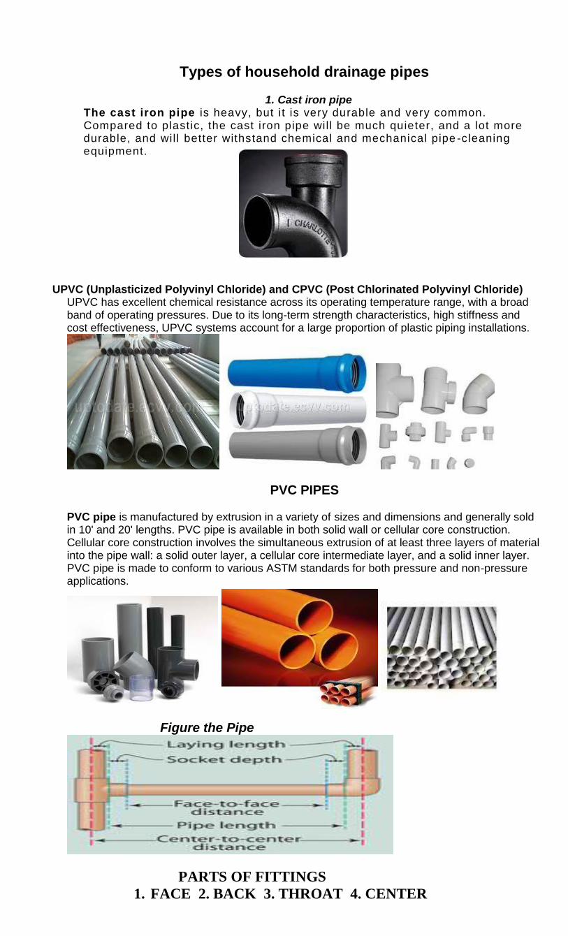
Figure the Pipe
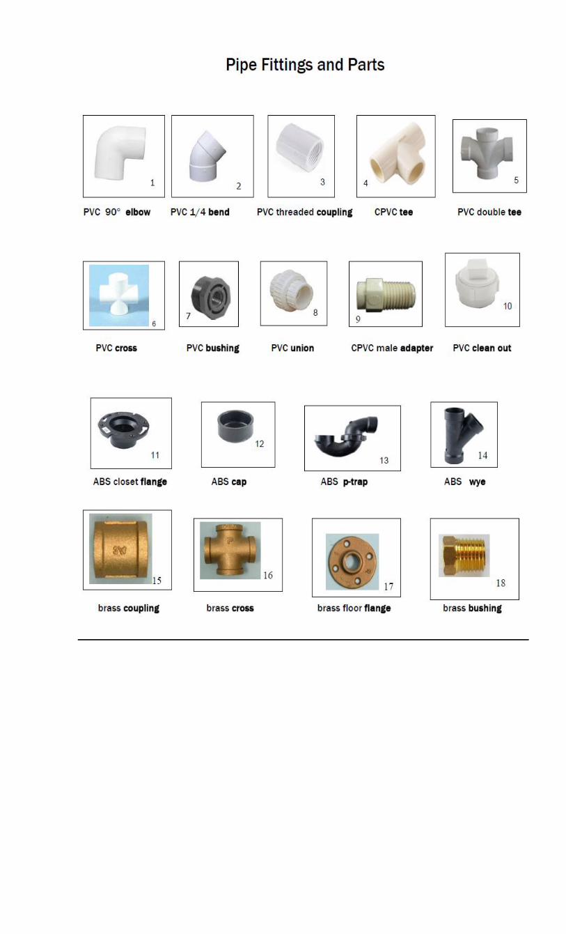
PARTS OF FITTINGS
1. FACE 2. BACK 3. THROAT 4. CENTER
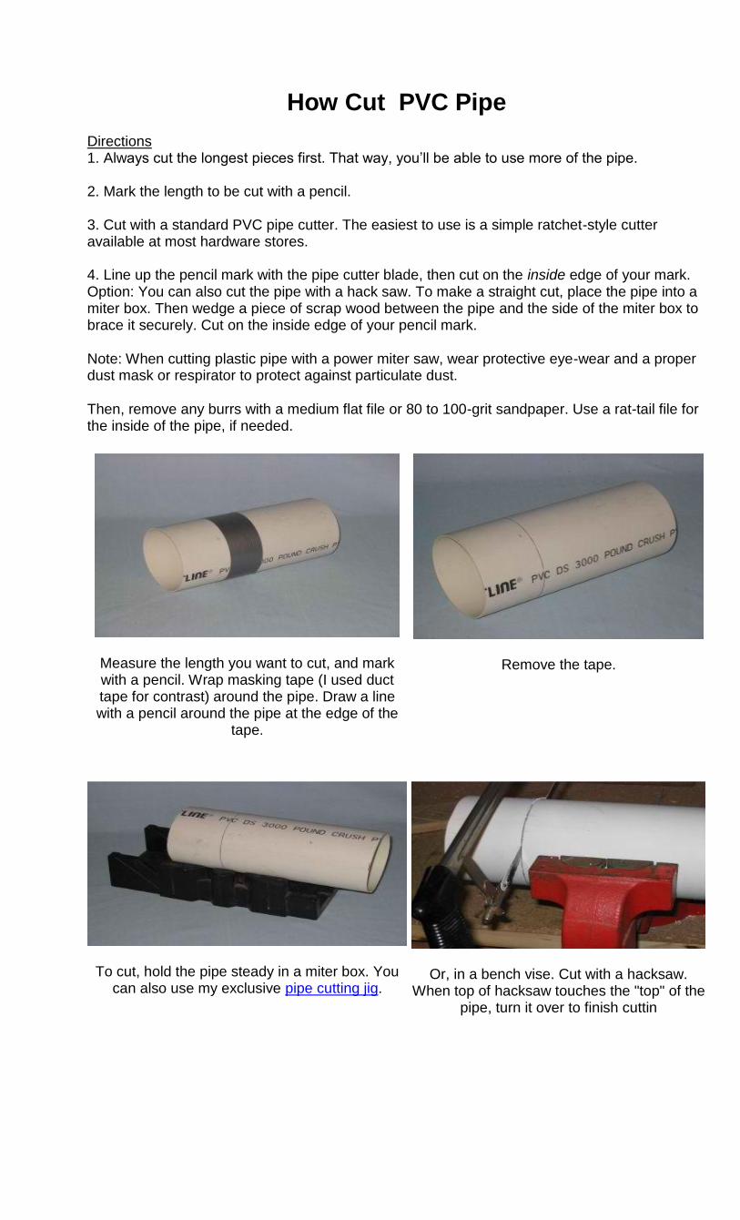
How Cut PVC Pipe
Directions 1. Always cut the longest pieces first. That way, you‘ll be able to use more of the pipe. 2. Mark the length to be cut with a pencil. 3. Cut with a standard PVC pipe cutter. The easiest to use is a simple ratchet-style cutter available at most hardware stores. 4. Line up the pencil mark with the pipe cutter blade, then cut on the inside edge of your mark. Option: You can also cut the pipe with a hack saw. To make a straight cut, place the pipe into a miter box. Then wedge a piece of scrap wood between the pipe and the side of the miter box to brace it securely. Cut on the inside edge of your pencil mark.
Note: When cutting plastic pipe with a power miter saw, wear protective eye-wear and a proper dust mask or respirator to protect against particulate dust.
Then, remove any burrs with a medium flat file or 80 to 100-grit sandpaper. Use a rat-tail file for the inside of the pipe, if needed.
Measure the length you want to cut, and mark with a pencil. Wrap masking tape (I used duct tape for contrast) around the pipe. Draw a line with a pencil around the pipe at the edge of the
tape.
Remove the tape.
To cut, hold the pipe steady in a miter box. You can also use my exclusive pipe cutting jig.
Or, in a bench vise. Cut with a hacksaw. When top of hacksaw touches the "top" of the
pipe, turn it over to finish cuttin
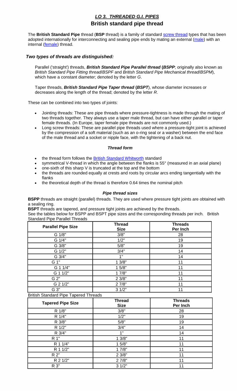
LO 3. THREADED G.I. PIPES
British standard pipe thread
The British Standard Pipe thread (BSP thread) is a family of standard screw thread types that has been adopted internationally for interconnecting and sealing pipe ends by mating an external (male) with an internal (female) thread.
Two types of threads are distinguished:
Parallel ('straight') threads, British Standard Pipe Parallel thread (BSPP; originally also known as
British Standard Pipe Fitting thread/BSPF and British Standard Pipe Mechanical thread/BSPM), which have a constant diameter; denoted by the letter G.
Taper threads, British Standard Pipe Taper thread (BSPT), whose diameter increases or decreases along the length of the thread; denoted by the letter R.
These can be combined into two types of joints:
Jointing threads: These are pipe threads where pressure-tightness is made through the mating of two threads together. They always use a taper male thread, but can have either parallel or taper female threads. (In Europe, taper female pipe threads are not commonly used.)
Long screw threads: These are parallel pipe threads used where a pressure-tight joint is achieved by the compression of a soft material (such as an o-ring seal or a washer) between the end face of the male thread and a socket or nipple face, with the tightening of a back nut.
Thread form
the thread form follows the British Standard Whitworth standard symmetrical V-thread in which the angle between the flanks is 55° (measured in an axial plane) one-sixth of this sharp V is truncated at the top and the bottom the threads are rounded equally at crests and roots by circular arcs ending tangentially with the
flanks the theoretical depth of the thread is therefore 0.64 times the nominal pitch
Pipe thread sizes
BSPP threads are straight (parallel) threads. They are used where pressure tight joints are obtained with a sealing ring. BSPT threads are tapered, and pressure tight joints are achieved by the threads. See the tables below for BSPP and BSPT pipe sizes and the corresponding threads per inch. British Standard Pipe Parallel Threads
Parallel Pipe Size Thread
Size Threads Per Inch
G 1/8" 3/8" 28
G 1/4" 1/2" 19
G 3/8" 5/8" 19
G 1/2" 3/4" 14
G 3/4" 1" 14
G 1" 1 3/8" 11
G 1 1/4" 1 5/8" 11
G 1 1/2" 1 7/8" 11
G 2" 2 3/8" 11
G 2 1/2" 2 7/8" 11
G 3" 3 1/2" 11
British Standard Pipe Tapered Threads
Tapered Pipe Size Thread
Size Threads Per Inch
R 1/8" 3/8" 28
R 1/4" 1/2" 19
R 3/8" 5/8" 19
R 1/2" 3/4" 14
R 3/4" 1" 14
R 1" 1 3/8" 11
R 1 1/4" 1 5/8" 11
R 1 1/2" 1 7/8" 11
R 2" 2 3/8" 11
R 2 1/2" 2 7/8" 11
R 3" 3 1/2" 11
A list of 16 thread sizes are defined by the standards, ranging from 1⁄16 to 6. The size number was originally based on the inner diameter measured in inches of a steel tube for which the thread was intended, but in the modern metric version of the standard is simply a size number.
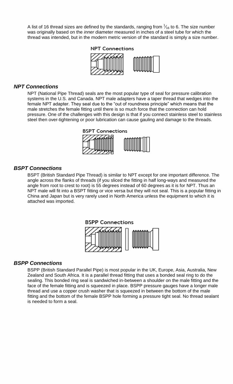
NPT Connections
NPT (National Pipe Thread) seals are the most popular type of seal for pressure calibration systems in the U.S. and Canada. NPT male adapters have a taper thread that wedges into the female NPT adapter. They seal due to the ―out of roundness principle‖ which means that the male stretches the female fitting until there is so much force that the connection can hold pressure. One of the challenges with this design is that if you connect stainless steel to stainless steel then over-tightening or poor lubrication can cause gauling and damage to the threads.
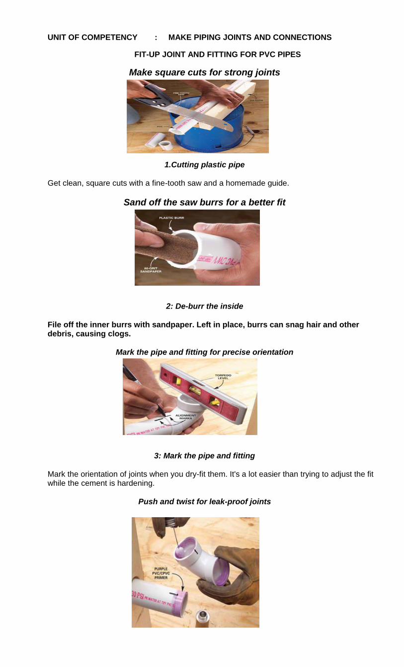
BSPT Connections
BSPT (British Standard Pipe Thread) is similar to NPT except for one important difference. The angle across the flanks of threads (if you sliced the fitting in half long-ways and measured the angle from root to crest to root) is 55 degrees instead of 60 degrees as it is for NPT. Thus an NPT male will fit into a BSPT fitting or vice versa but they will not seal. This is a popular fitting in China and Japan but is very rarely used in North America unless the equipment to which it is attached was imported.
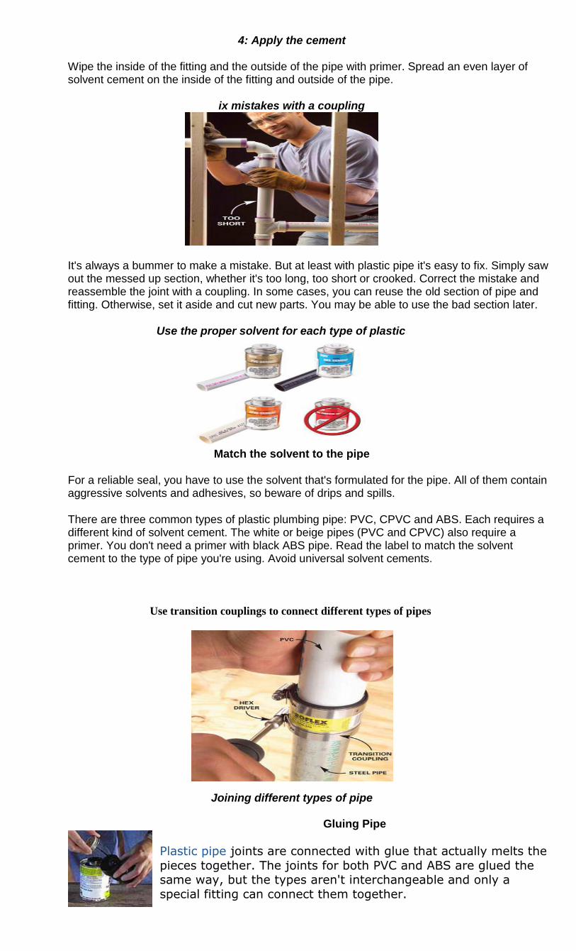
BSPP Connections
BSPP (British Standard Parallel Pipe) is most popular in the UK, Europe, Asia, Australia, New Zealand and South Africa. It is a parallel thread fitting that uses a bonded seal ring to do the sealing. This bonded ring seal is sandwiched in-between a shoulder on the male fitting and the face of the female fitting and is squeezed in place. BSPP pressure gauges have a longer male thread and use a copper crush washer that is squeezed in between the bottom of the male fitting and the bottom of the female BSPP hole forming a pressure tight seal. No thread sealant is needed to form a seal.
UNIT OF COMPETENCY : MAKE PIPING JOINTS AND CONNECTIONS
FIT-UP JOINT AND FITTING FOR PVC PIPES
Make square cuts for strong joints
1.Cutting plastic pipe
Get clean, square cuts with a fine-tooth saw and a homemade guide.
Sand off the saw burrs for a better fit
2: De-burr the inside
File off the inner burrs with sandpaper. Left in place, burrs can snag hair and other debris, causing clogs.
Mark the pipe and fitting for precise orientation
3: Mark the pipe and fitting
Mark the orientation of joints when you dry-fit them. It's a lot easier than trying to adjust the fit while the cement is hardening.
Push and twist for leak-proof joints
4: Apply the cement
Wipe the inside of the fitting and the outside of the pipe with primer. Spread an even layer of solvent cement on the inside of the fitting and outside of the pipe.
ix mistakes with a coupling
It's always a bummer to make a mistake. But at least with plastic pipe it's easy to fix. Simply saw out the messed up section, whether it's too long, too short or crooked. Correct the mistake and reassemble the joint with a coupling. In some cases, you can reuse the old section of pipe and fitting. Otherwise, set it aside and cut new parts. You may be able to use the bad section later.
Use the proper solvent for each type of plastic
Match the solvent to the pipe
For a reliable seal, you have to use the solvent that's formulated for the pipe. All of them contain aggressive solvents and adhesives, so beware of drips and spills.
There are three common types of plastic plumbing pipe: PVC, CPVC and ABS. Each requires a different kind of solvent cement. The white or beige pipes (PVC and CPVC) also require a primer. You don't need a primer with black ABS pipe. Read the label to match the solvent cement to the type of pipe you're using. Avoid universal solvent cements.
Use transition couplings to connect different types of pipes
Joining different types of pipe
Gluing Pipe
Plastic pipe joints are connected with glue that actually melts the
pieces together. The joints for both PVC and ABS are glued the same way, but the types aren't interchangeable and only a
special fitting can connect them together.
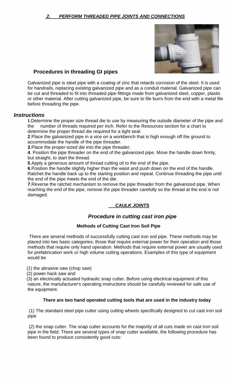
2. PERFORM THREADED PIPE JOINTS AND CONNECTIONS
Procedures in threading GI pipes
Galvanized pipe is steel pipe with a coating of zinc that retards corrosion of the steel. It is used for handrails, replacing existing galvanized pipe and as a conduit material. Galvanized pipe can be cut and threaded to fit into threaded pipe fittings made from galvanized steel, copper, plastic or other material. After cutting galvanized pipe, be sure to file burrs from the end with a metal file before threading the pipe.
Instructions 1.Determine the proper size thread die to use by measuring the outside diameter of the pipe and
the number of threads required per inch. Refer to the Resources section for a chart to determine the proper thread die required for a tight seal. 2.Place the galvanized pipe in a vice on a workbench that is high enough off the ground to accommodate the handle of the pipe threader. 3.Place the proper-sized die into the pipe threader. 4. Position the pipe threader on the end of the galvanized pipe. Move the handle down firmly, but straight, to start the thread. 5.Apply a generous amount of thread cutting oil to the end of the pipe. 6.Position the handle slightly higher than the waist and push down on the end of the handle. Ratchet the handle back up to the starting position and repeat. Continue threading the pipe until the end of the pipe meets the end of the die. 7.Reverse the ratchet mechanism to remove the pipe threader from the galvanized pipe. When reaching the end of the pipe, remove the pipe threader carefully so the thread at the end is not damaged.
CAULK JOINTS
Procedure in cutting cast iron pipe
Methods of Cutting Cast Iron Soil Pipe
There are several methods of successfully cutting cast iron soil pipe. These methods may be placed into two basic categories; those that require external power for their operation and those methods that require only hand operation. Methods that require external power are usually used for prefabrication work or high volume cutting operations. Examples of this type of equipment would be
(1) the abrasive saw (chop saw) (2) power hack saw and (3) an electrically actuated hydraulic snap cutter. Before using electrical equipment of this
nature, the manufacturer's operating instructions should be carefully reviewed for safe use of the equipment.
There are two hand operated cutting tools that are used in the industry today
(1) The standard steel pipe cutter using cutting wheels specifically designed to cut cast iron soil pipe
(2) the snap cutter. The snap cutter accounts for the majority of all cuts made on cast iron soil pipe in the field. There are several types of snap cutter available, the following procedure has been found to produce consistently good cuts:
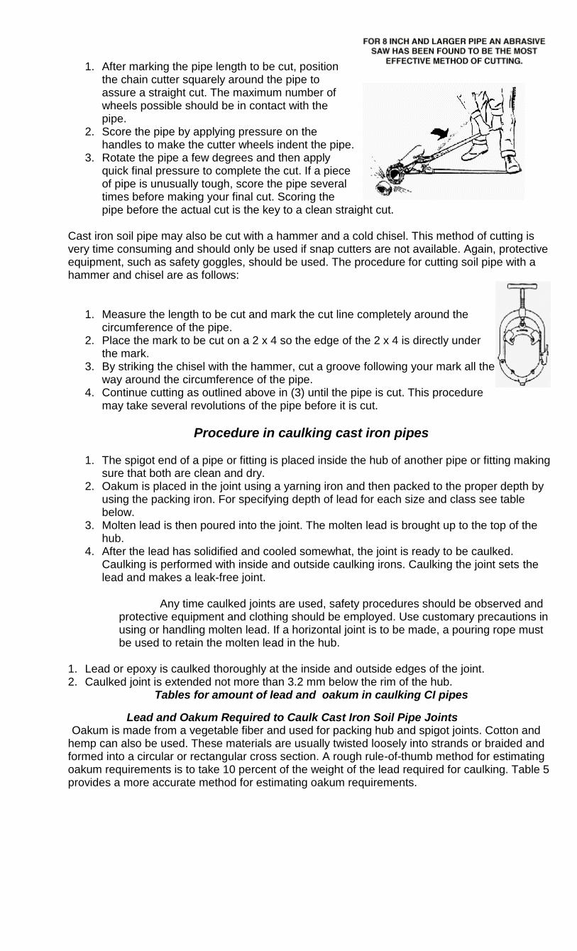
1. After marking the pipe length to be cut, position the chain cutter squarely around the pipe to assure a straight cut. The maximum number of wheels possible should be in contact with the pipe.
2. Score the pipe by applying pressure on the handles to make the cutter wheels indent the pipe.
3. Rotate the pipe a few degrees and then apply quick final pressure to complete the cut. If a piece of pipe is unusually tough, score the pipe several times before making your final cut. Scoring the pipe before the actual cut is the key to a clean straight cut.
Cast iron soil pipe may also be cut with a hammer and a cold chisel. This method of cutting is very time consuming and should only be used if snap cutters are not available. Again, protective equipment, such as safety goggles, should be used. The procedure for cutting soil pipe with a hammer and chisel are as follows:
1. Measure the length to be cut and mark the cut line completely around the circumference of the pipe.
2. Place the mark to be cut on a 2 x 4 so the edge of the 2 x 4 is directly under the mark.
3. By striking the chisel with the hammer, cut a groove following your mark all the way around the circumference of the pipe.
4. Continue cutting as outlined above in (3) until the pipe is cut. This procedure may take several revolutions of the pipe before it is cut.
Procedure in caulking cast iron pipes
1. The spigot end of a pipe or fitting is placed inside the hub of another pipe or fitting making sure that both are clean and dry.
2. Oakum is placed in the joint using a yarning iron and then packed to the proper depth by using the packing iron. For specifying depth of lead for each size and class see table below.
3. Molten lead is then poured into the joint. The molten lead is brought up to the top of the hub.
4. After the lead has solidified and cooled somewhat, the joint is ready to be caulked. Caulking is performed with inside and outside caulking irons. Caulking the joint sets the lead and makes a leak-free joint.
Any time caulked joints are used, safety procedures should be observed and protective equipment and clothing should be employed. Use customary precautions in using or handling molten lead. If a horizontal joint is to be made, a pouring rope must be used to retain the molten lead in the hub.
1. Lead or epoxy is caulked thoroughly at the inside and outside edges of the joint. 2. Caulked joint is extended not more than 3.2 mm below the rim of the hub.
Tables for amount of lead and oakum in caulking CI pipes
Lead and Oakum Required to Caulk Cast Iron Soil Pipe Joints Oakum is made from a vegetable fiber and used for packing hub and spigot joints. Cotton and
hemp can also be used. These materials are usually twisted loosely into strands or braided and formed into a circular or rectangular cross section. A rough rule-of-thumb method for estimating oakum requirements is to take 10 percent of the weight of the lead required for caulking. Table 5 provides a more accurate method for estimating oakum requirements.
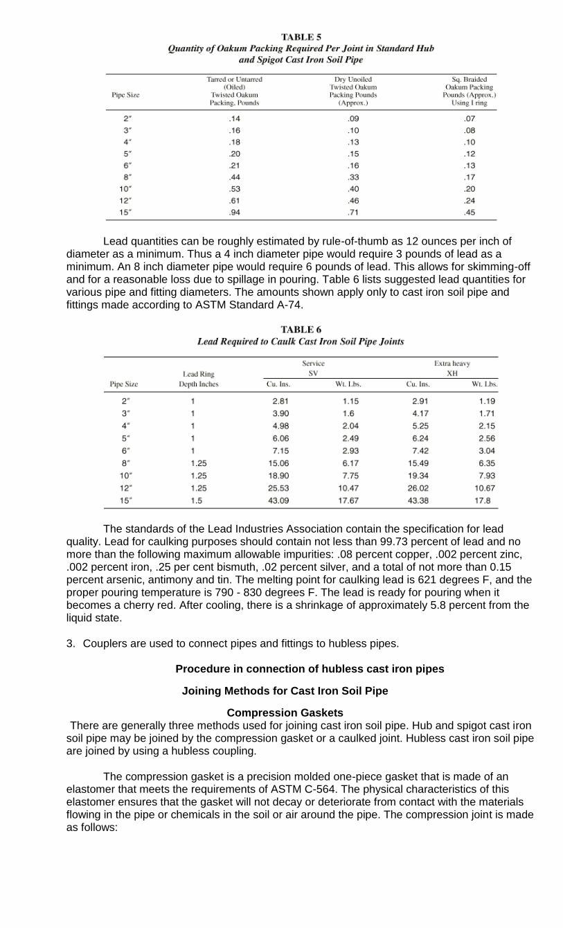
Lead quantities can be roughly estimated by rule-of-thumb as 12 ounces per inch of diameter as a minimum. Thus a 4 inch diameter pipe would require 3 pounds of lead as a minimum. An 8 inch diameter pipe would require 6 pounds of lead. This allows for skimming-off and for a reasonable loss due to spillage in pouring. Table 6 lists suggested lead quantities for various pipe and fitting diameters. The amounts shown apply only to cast iron soil pipe and fittings made according to ASTM Standard A-74.
The standards of the Lead Industries Association contain the specification for lead quality. Lead for caulking purposes should contain not less than 99.73 percent of lead and no more than the following maximum allowable impurities: .08 percent copper, .002 percent zinc, .002 percent iron, .25 per cent bismuth, .02 percent silver, and a total of not more than 0.15 percent arsenic, antimony and tin. The melting point for caulking lead is 621 degrees F, and the proper pouring temperature is 790 - 830 degrees F. The lead is ready for pouring when it becomes a cherry red. After cooling, there is a shrinkage of approximately 5.8 percent from the liquid state.
3. Couplers are used to connect pipes and fittings to hubless pipes.
Procedure in connection of hubless cast iron pipes
Joining Methods for Cast Iron Soil Pipe
Compression Gaskets There are generally three methods used for joining cast iron soil pipe. Hub and spigot cast iron
soil pipe may be joined by the compression gasket or a caulked joint. Hubless cast iron soil pipe are joined by using a hubless coupling.
The compression gasket is a precision molded one-piece gasket that is made of an elastomer that meets the requirements of ASTM C-564. The physical characteristics of this elastomer ensures that the gasket will not decay or deteriorate from contact with the materials flowing in the pipe or chemicals in the soil or air around the pipe. The compression joint is made as follows:
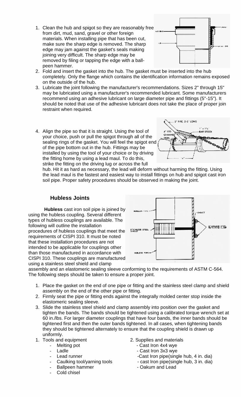
1. Clean the hub and spigot so they are reasonably free from dirt, mud, sand, gravel or other foreign materials. When installing pipe that has been cut, make sure the sharp edge is removed. The sharp edge may jam against the gasket's seals making joining very difficult. The sharp edge may be removed by filing or tapping the edge with a ball-peen hammer.
2. Fold and insert the gasket into the hub. The gasket must be inserted into the hub completely. Only the flange which contains the identification information remains exposed on the outside of the hub.
3. Lubricate the joint following the manufacturer's recommendations. Sizes 2" through 15" may be lubricated using a manufacturer's recommended lubricant. Some manufacturers recommend using an adhesive lubricant on large diameter pipe and fittings (5"-15"). It should be noted that use of the adhesive lubricant does not take the place of proper join restraint when required.
4. Align the pipe so that it is straight. Using the tool of your choice, push or pull the spigot through all of the sealing rings of the gasket. You will feel the spigot end of the pipe bottom out in the hub. Fittings may be installed by using the tool of your choice or by driving the fitting home by using a lead maul. To do this, strike the fitting on the driving lug or across the full hub. Hit it as hard as necessary, the lead will deform without harming the fitting. Using the lead maul is the fastest and easiest way to install fittings on hub and spigot cast iron soil pipe. Proper safety procedures should be observed in making the joint.
Hubless Joints
Hubless cast iron soil pipe is joined by using the hubless coupling. Several different types of hubless couplings are available. The following will outline the installation procedures of hubless couplings that meet the requirements of CISPI 310. It must be noted that these installation procedures are not intended to be applicable for couplings other than those manufactured in accordance with CISPI 310. These couplings are manufactured using a stainless steel shield and clamp assembly and an elastomeric sealing sleeve conforming to the requirements of ASTM C-564. The following steps should be taken to ensure a proper joint.
1. Place the gasket on the end of one pipe or fitting and the stainless steel clamp and shield assembly on the end of the other pipe or fitting.
2. Firmly seat the pipe or fitting ends against the integrally molded center stop inside the elastomeric sealing sleeve.
3. Slide the stainless steel shield and clamp assembly into position over the gasket and tighten the bands. The bands should be tightened using a calibrated torque wrench set at 60 in./lbs. For larger diameter couplings that have four bands, the inner bands should be tightened first and then the outer bands tightened. In all cases, when tightening bands they should be tightened alternately to ensure that the coupling shield is drawn up uniformly.
1. Tools and equipment 2. Supplies and materials - Melting pot - Cast Iron 4x4 wye - Ladle - Cast Iron 3x3 wye - Lead runner -Cast Iron pipe(single hub, 4 in. dia) - Caulking tool/yarning tools - cast Iron pipe(single hub, 3 in. dia) - Ballpeen hammer - Oakum and Lead - Cold chisel
PERFORM MINOR CONSTRUCTION WORKS
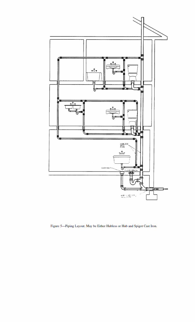
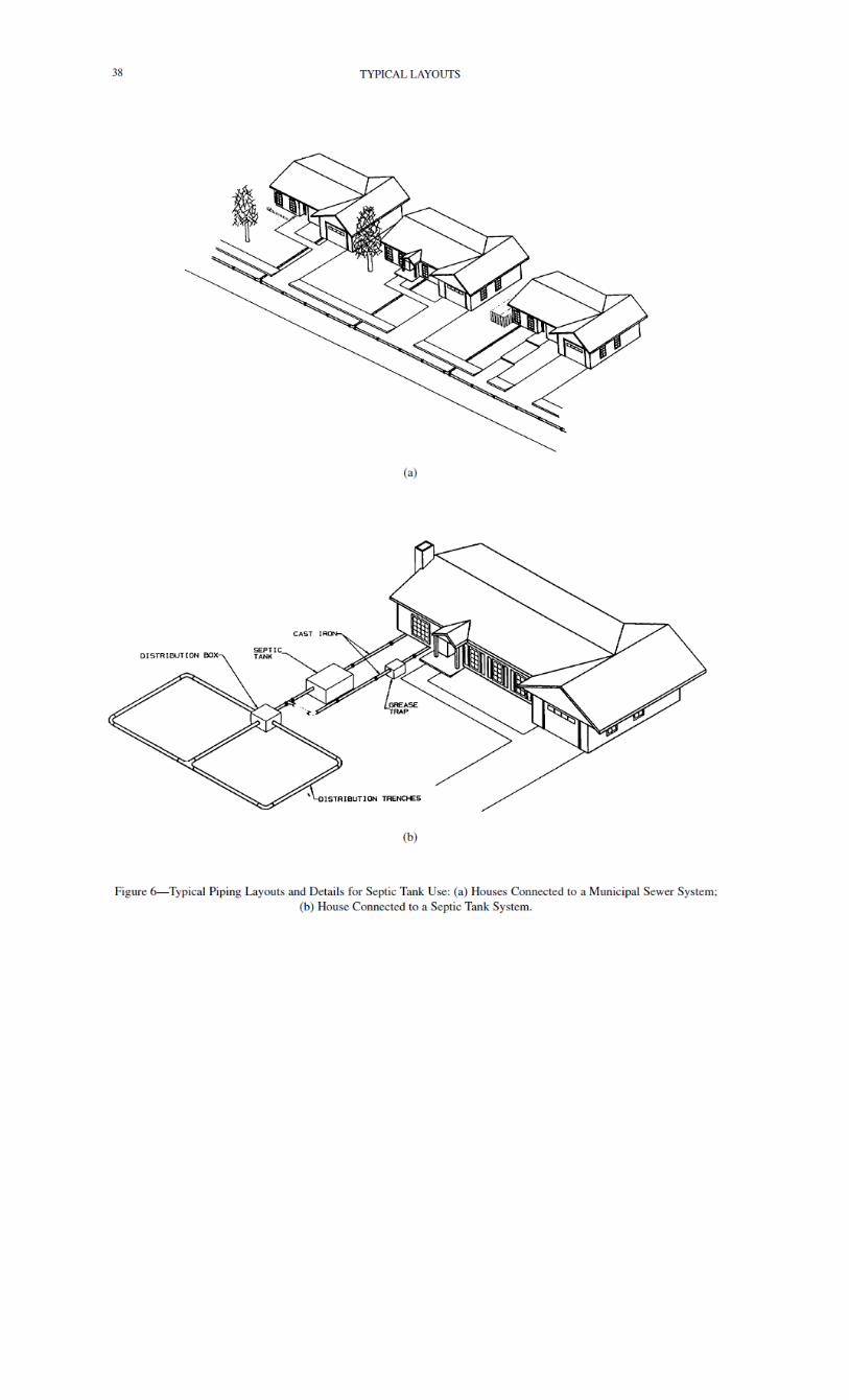
PERFORM PIPING LAYOUTSWORKS
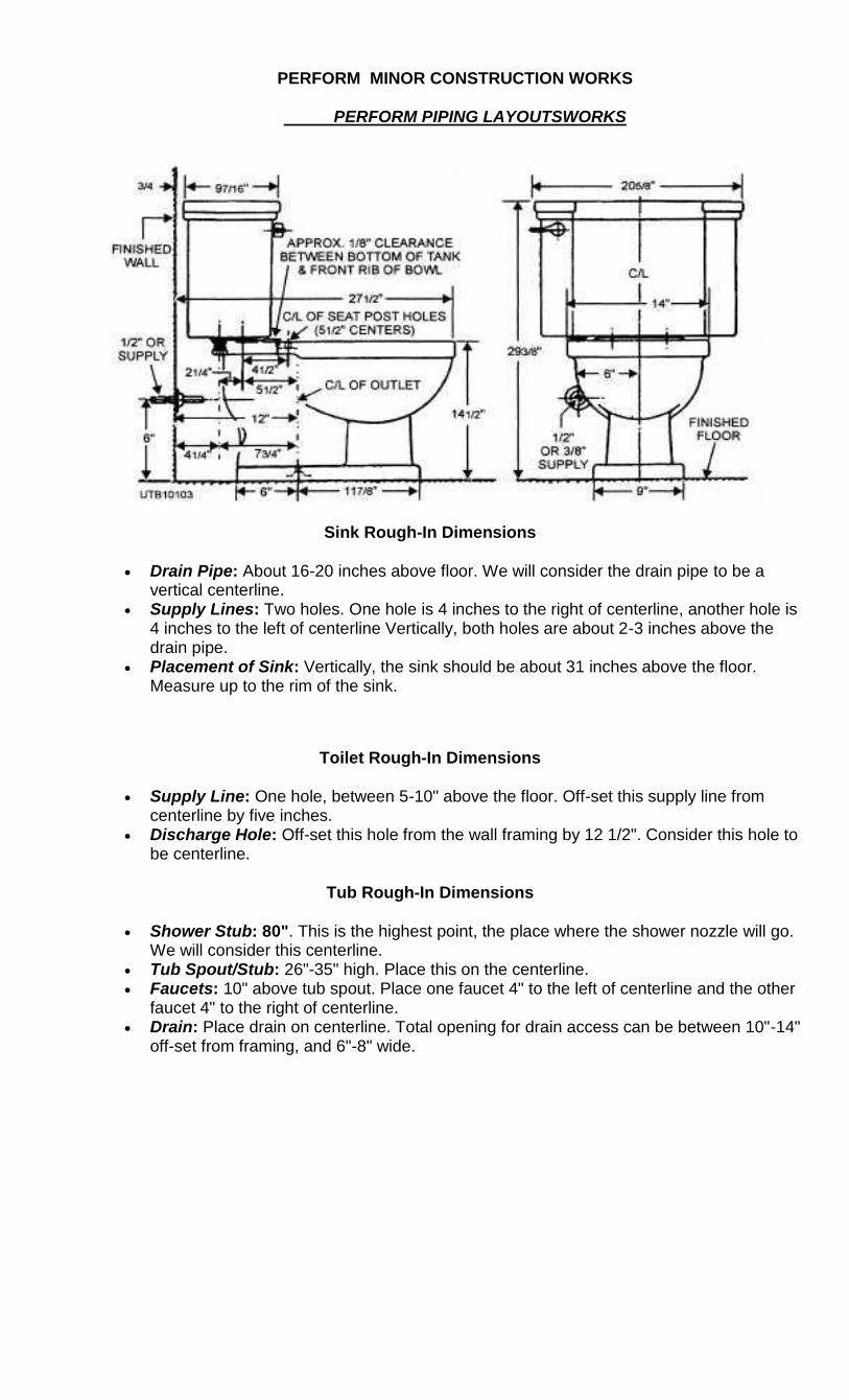
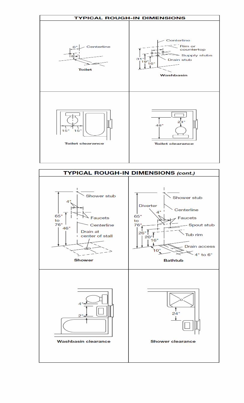
Sink Rough-In Dimensions
Drain Pipe: About 16-20 inches above floor. We will consider the drain pipe to be a vertical centerline.
Supply Lines: Two holes. One hole is 4 inches to the right of centerline, another hole is 4 inches to the left of centerline Vertically, both holes are about 2-3 inches above the drain pipe.
Placement of Sink: Vertically, the sink should be about 31 inches above the floor. Measure up to the rim of the sink.
Toilet Rough-In Dimensions
Supply Line: One hole, between 5-10" above the floor. Off-set this supply line from centerline by five inches.
Discharge Hole: Off-set this hole from the wall framing by 12 1/2". Consider this hole to be centerline.
Tub Rough-In Dimensions
Shower Stub: 80". This is the highest point, the place where the shower nozzle will go. We will consider this centerline.
Tub Spout/Stub: 26"-35" high. Place this on the centerline. Faucets: 10" above tub spout. Place one faucet 4" to the left of centerline and the other
faucet 4" to the right of centerline. Drain: Place drain on centerline. Total opening for drain access can be between 10"-14"
off-set from framing, and 6"-8" wide.
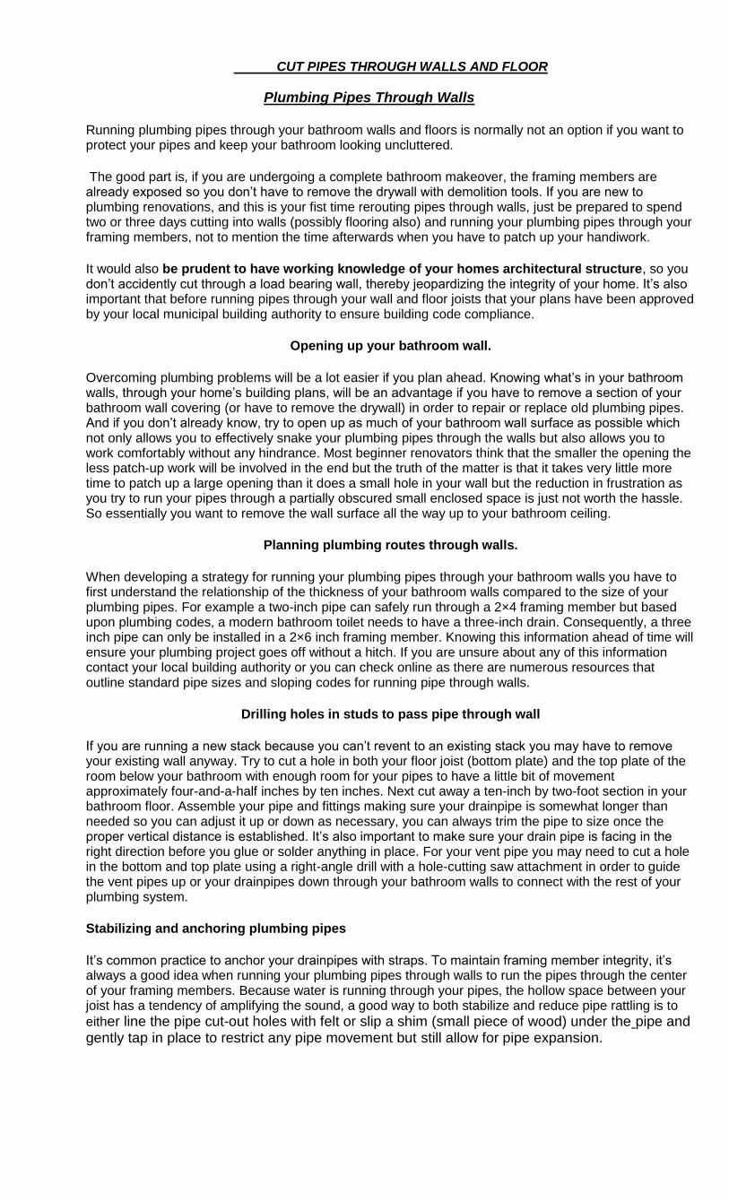
CUT PIPES THROUGH WALLS AND FLOOR
Plumbing Pipes Through Walls
Running plumbing pipes through your bathroom walls and floors is normally not an option if you want to protect your pipes and keep your bathroom looking uncluttered.
The good part is, if you are undergoing a complete bathroom makeover, the framing members are already exposed so you don‘t have to remove the drywall with demolition tools. If you are new to plumbing renovations, and this is your fist time rerouting pipes through walls, just be prepared to spend two or three days cutting into walls (possibly flooring also) and running your plumbing pipes through your framing members, not to mention the time afterwards when you have to patch up your handiwork.
It would also be prudent to have working knowledge of your homes architectural structure, so you don‘t accidently cut through a load bearing wall, thereby jeopardizing the integrity of your home. It‘s also important that before running pipes through your wall and floor joists that your plans have been approved by your local municipal building authority to ensure building code compliance.
Opening up your bathroom wall.
Overcoming plumbing problems will be a lot easier if you plan ahead. Knowing what‘s in your bathroom walls, through your home‘s building plans, will be an advantage if you have to remove a section of your bathroom wall covering (or have to remove the drywall) in order to repair or replace old plumbing pipes. And if you don‘t already know, try to open up as much of your bathroom wall surface as possible which not only allows you to effectively snake your plumbing pipes through the walls but also allows you to work comfortably without any hindrance. Most beginner renovators think that the smaller the opening the less patch-up work will be involved in the end but the truth of the matter is that it takes very little more time to patch up a large opening than it does a small hole in your wall but the reduction in frustration as you try to run your pipes through a partially obscured small enclosed space is just not worth the hassle. So essentially you want to remove the wall surface all the way up to your bathroom ceiling.
Planning plumbing routes through walls.
When developing a strategy for running your plumbing pipes through your bathroom walls you have to first understand the relationship of the thickness of your bathroom walls compared to the size of your plumbing pipes. For example a two-inch pipe can safely run through a 2×4 framing member but based upon plumbing codes, a modern bathroom toilet needs to have a three-inch drain. Consequently, a three inch pipe can only be installed in a 2×6 inch framing member. Knowing this information ahead of time will ensure your plumbing project goes off without a hitch. If you are unsure about any of this information contact your local building authority or you can check online as there are numerous resources that outline standard pipe sizes and sloping codes for running pipe through walls.
Drilling holes in studs to pass pipe through wall
If you are running a new stack because you can‘t revent to an existing stack you may have to remove your existing wall anyway. Try to cut a hole in both your floor joist (bottom plate) and the top plate of the room below your bathroom with enough room for your pipes to have a little bit of movement approximately four-and-a-half inches by ten inches. Next cut away a ten-inch by two-foot section in your bathroom floor. Assemble your pipe and fittings making sure your drainpipe is somewhat longer than needed so you can adjust it up or down as necessary, you can always trim the pipe to size once the proper vertical distance is established. It‘s also important to make sure your drain pipe is facing in the right direction before you glue or solder anything in place. For your vent pipe you may need to cut a hole in the bottom and top plate using a right-angle drill with a hole-cutting saw attachment in order to guide the vent pipes up or your drainpipes down through your bathroom walls to connect with the rest of your plumbing system.
Stabilizing and anchoring plumbing pipes
It‘s common practice to anchor your drainpipes with straps. To maintain framing member integrity, it‘s always a good idea when running your plumbing pipes through walls to run the pipes through the center of your framing members. Because water is running through your pipes, the hollow space between your joist has a tendency of amplifying the sound, a good way to both stabilize and reduce pipe rattling is to
either line the pipe cut-out holes with felt or slip a shim (small piece of wood) under the pipe and gently tap in place to restrict any pipe movement but still allow for pipe expansion.
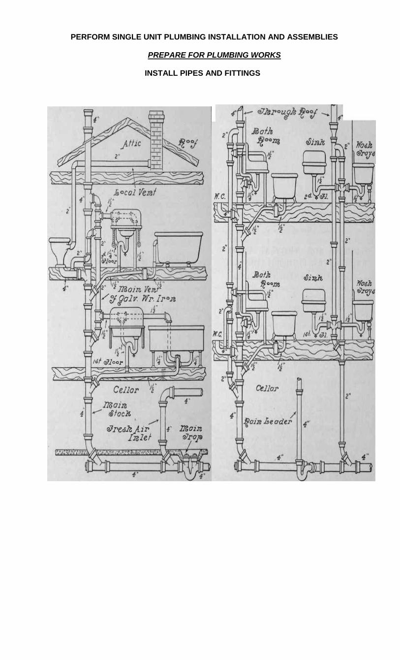
PERFORM SINGLE UNIT PLUMBING INSTALLATION AND ASSEMBLIES
PREPARE FOR PLUMBING WORKS
INSTALL PIPES AND FITTINGS
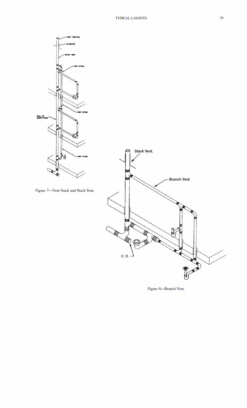
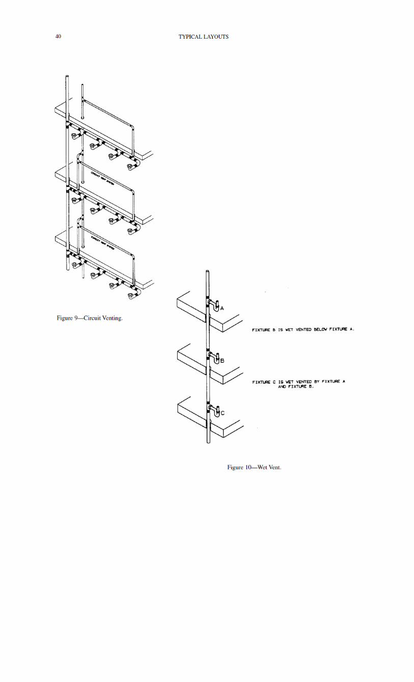
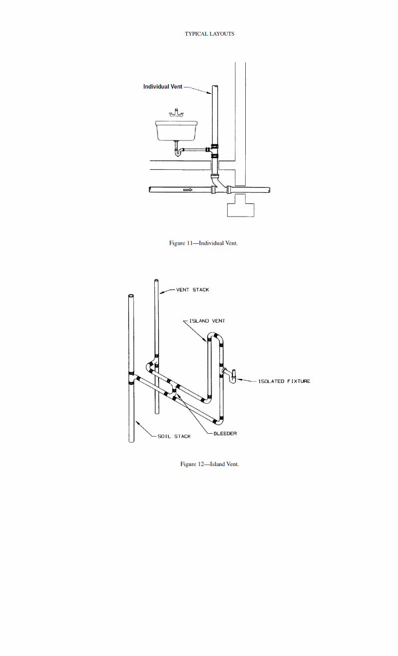
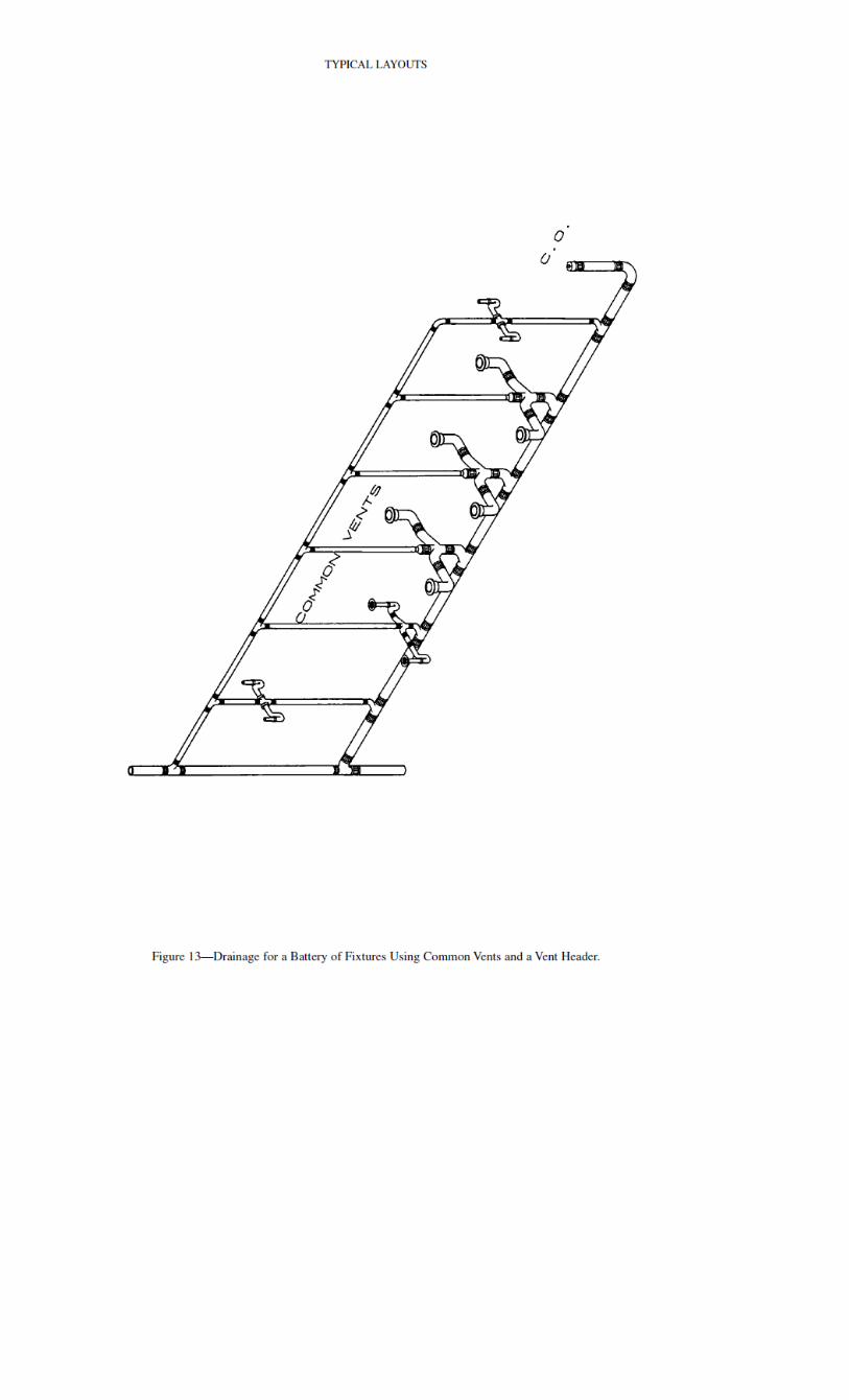
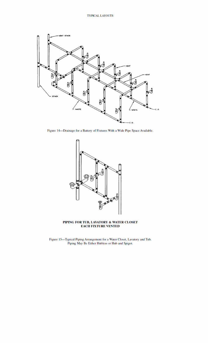
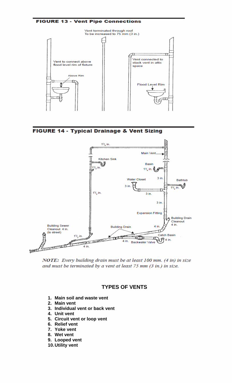
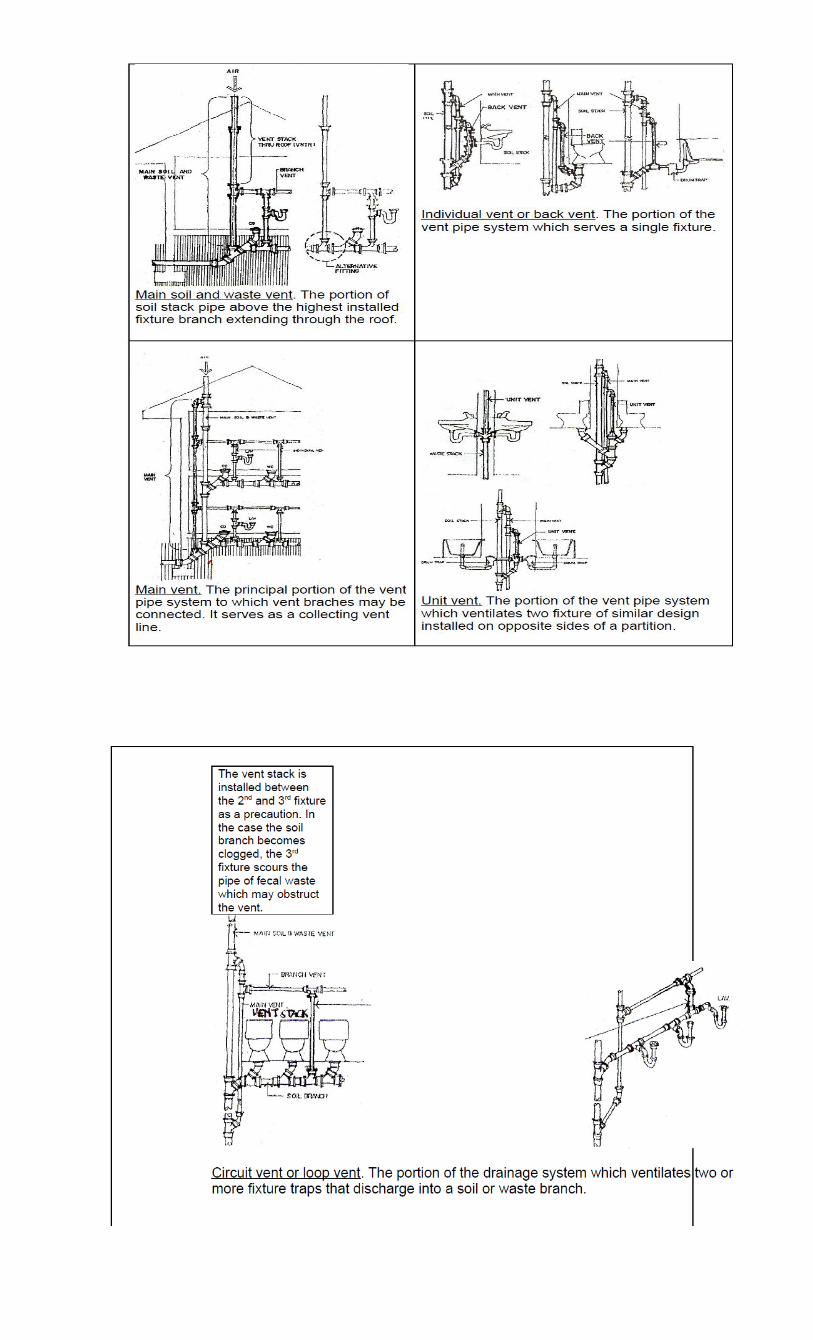
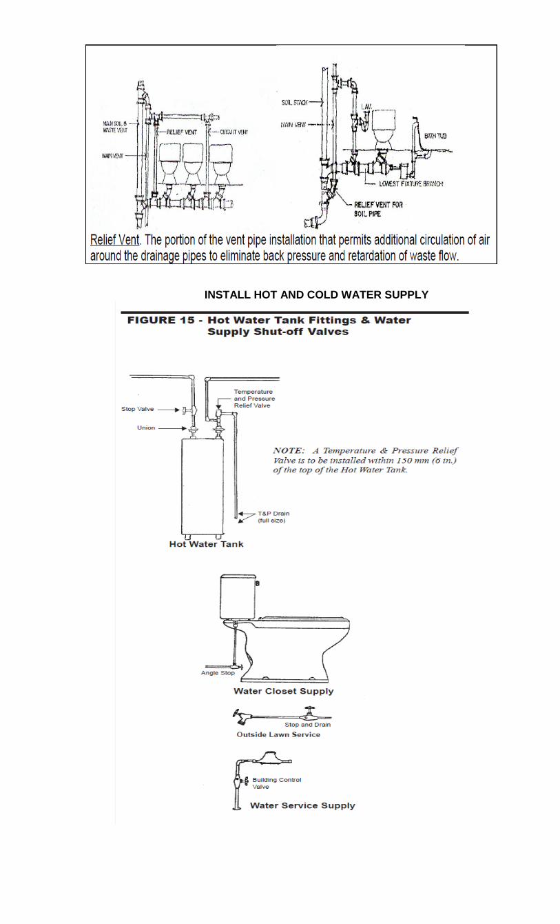
TYPES OF VENTS
1. Main soil and waste vent 2. Main vent 3. Individual vent or back vent 4. Unit vent 5. Circuit vent or loop vent 6. Relief vent 7. Yoke vent 8. Wet vent 9. Looped vent 10. Utility vent
INSTALL HOT AND COLD WATER SUPPLY
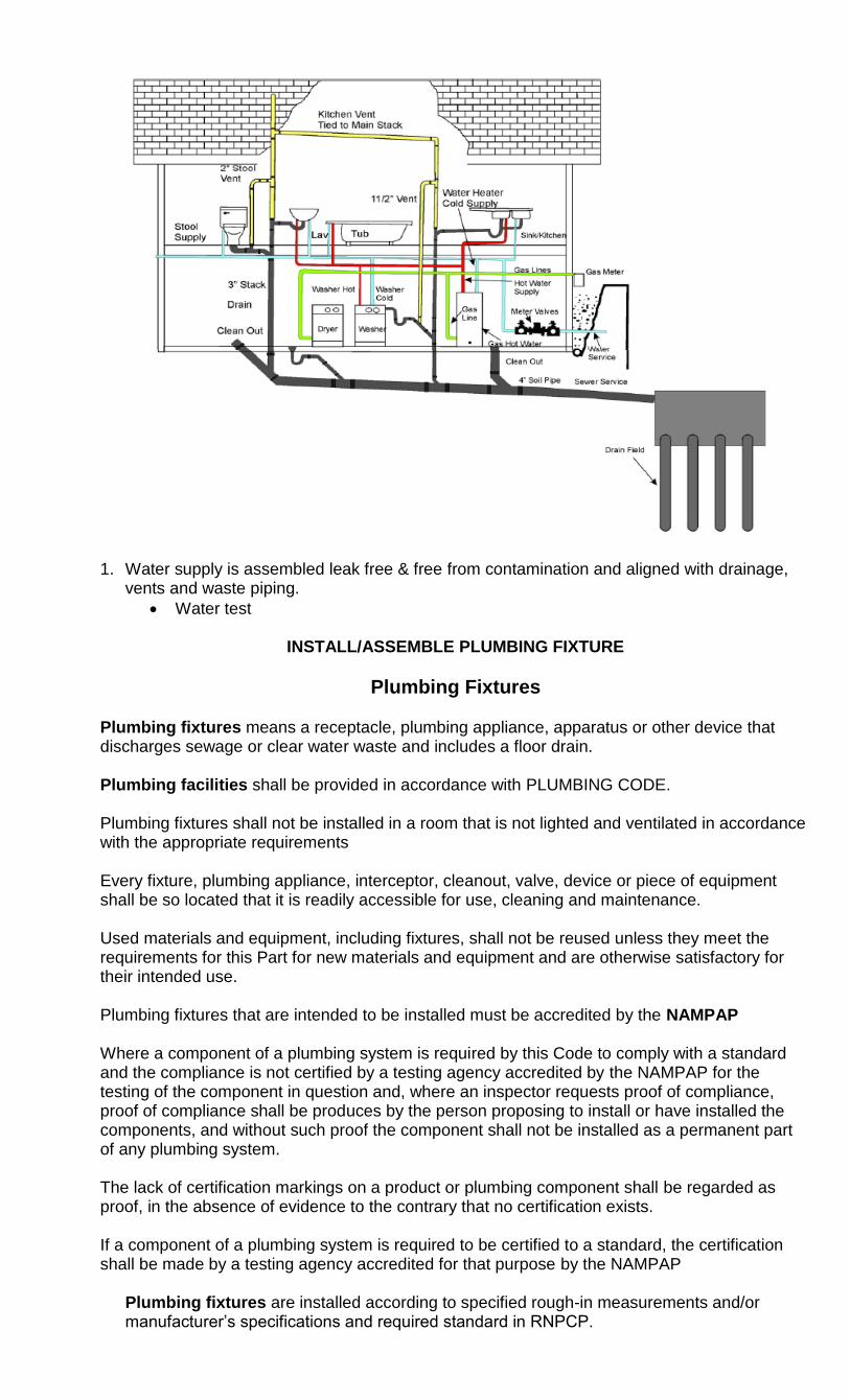
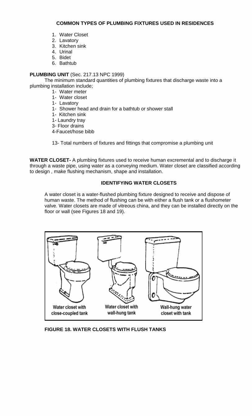
1. Water supply is assembled leak free & free from contamination and aligned with drainage,
vents and waste piping.
Water test
INSTALL/ASSEMBLE PLUMBING FIXTURE
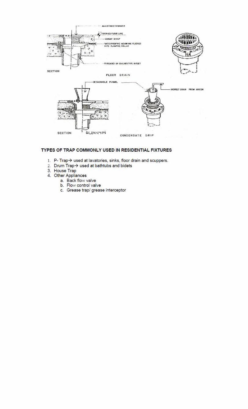
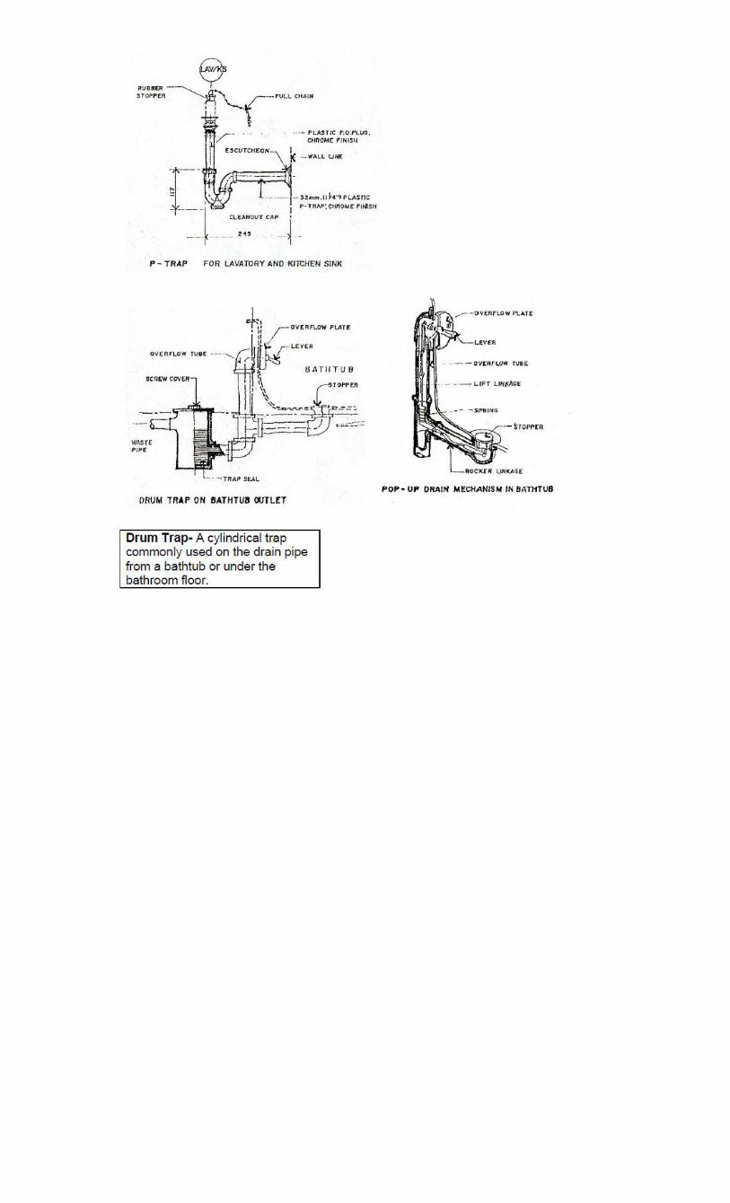
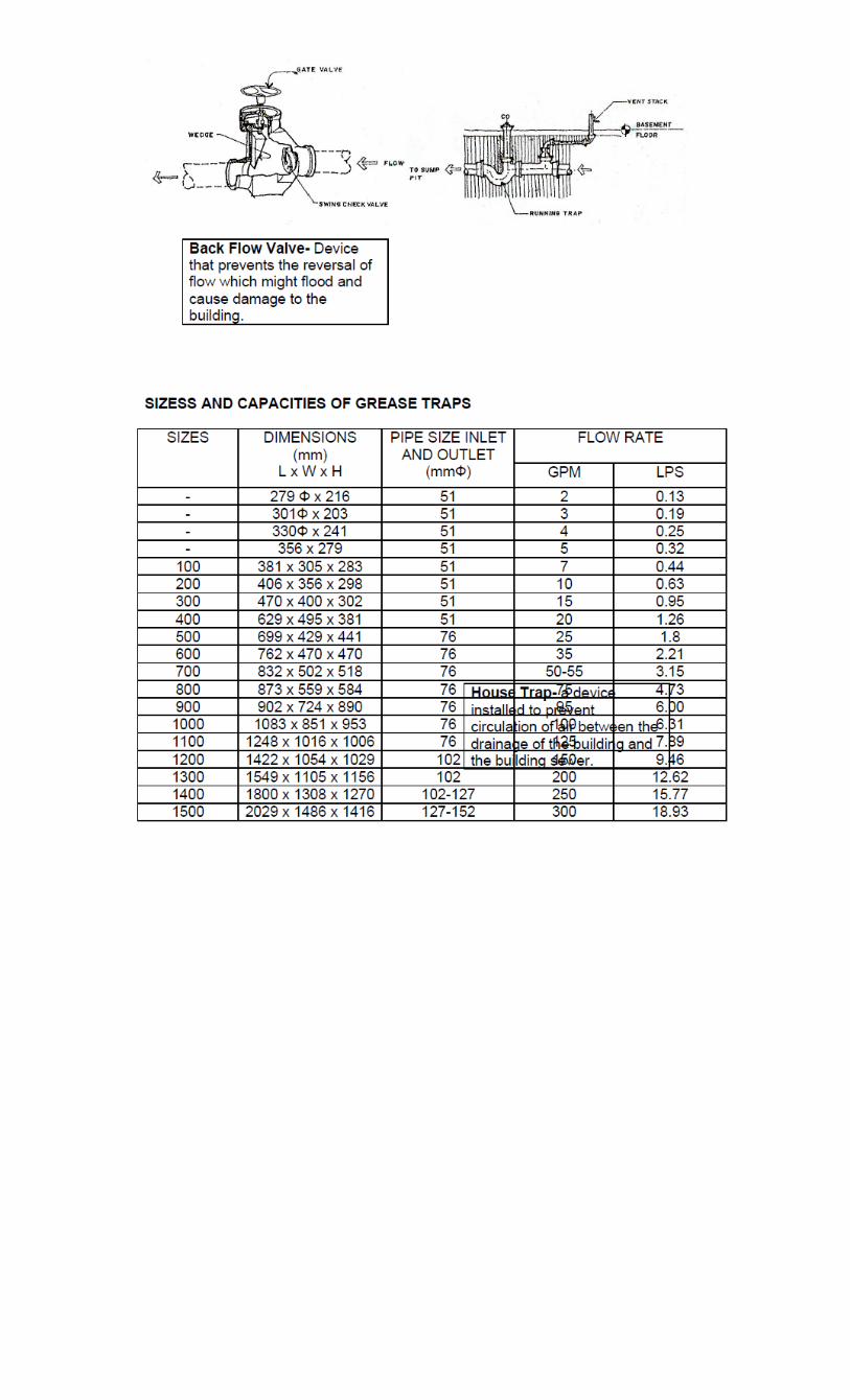
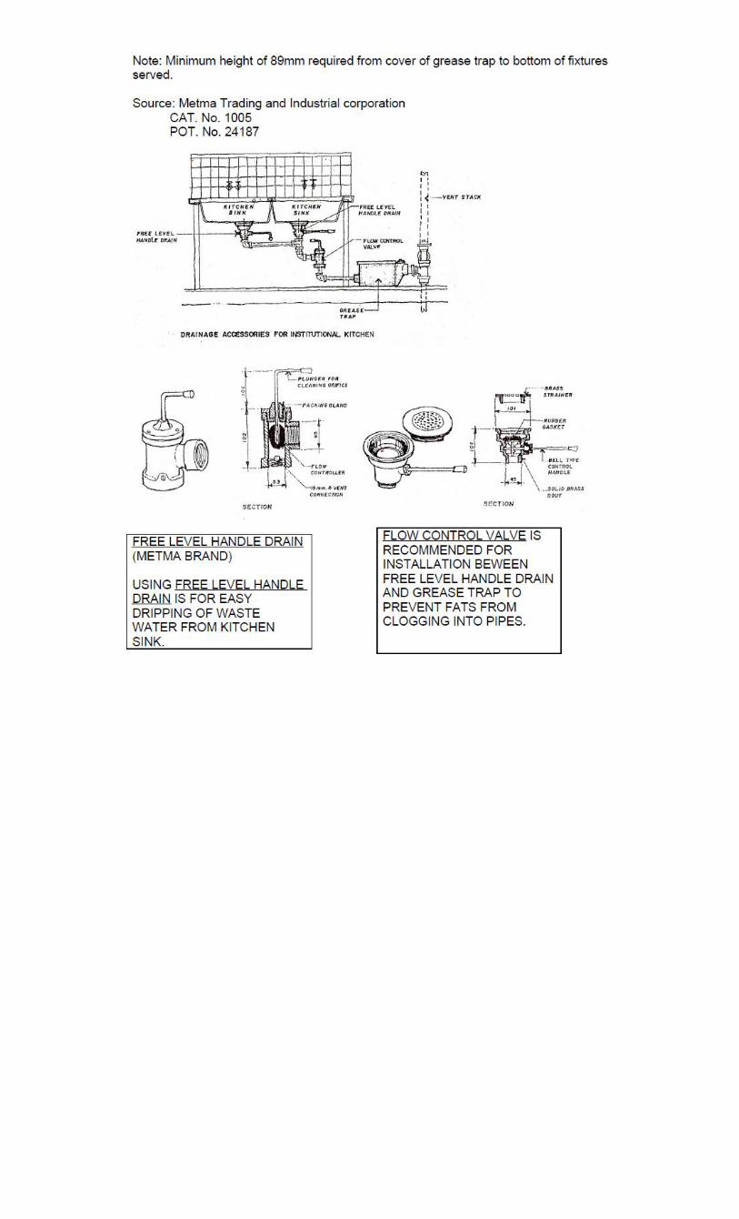
Plumbing Fixtures
Plumbing fixtures means a receptacle, plumbing appliance, apparatus or other device that discharges sewage or clear water waste and includes a floor drain. Plumbing facilities shall be provided in accordance with PLUMBING CODE. Plumbing fixtures shall not be installed in a room that is not lighted and ventilated in accordance with the appropriate requirements Every fixture, plumbing appliance, interceptor, cleanout, valve, device or piece of equipment shall be so located that it is readily accessible for use, cleaning and maintenance. Used materials and equipment, including fixtures, shall not be reused unless they meet the requirements for this Part for new materials and equipment and are otherwise satisfactory for their intended use. Plumbing fixtures that are intended to be installed must be accredited by the NAMPAP Where a component of a plumbing system is required by this Code to comply with a standard and the compliance is not certified by a testing agency accredited by the NAMPAP for the testing of the component in question and, where an inspector requests proof of compliance, proof of compliance shall be produces by the person proposing to install or have installed the components, and without such proof the component shall not be installed as a permanent part of any plumbing system. The lack of certification markings on a product or plumbing component shall be regarded as proof, in the absence of evidence to the contrary that no certification exists. If a component of a plumbing system is required to be certified to a standard, the certification shall be made by a testing agency accredited for that purpose by the NAMPAP
Plumbing fixtures are installed according to specified rough-in measurements and/or manufacturer‘s specifications and required standard in RNPCP.
COMMON TYPES OF PLUMBING FIXTURES USED IN RESIDENCES
1. Water Closet 2. Lavatory 3. Kitchen sink 4. Urinal 5. Bidet 6. Bathtub
PLUMBING UNIT (Sec. 217.13 NPC 1999) The minimum standard quantities of plumbing fixtures that discharge waste into a plumbing installation include;
1- Water meter 1- Water closet 1- Lavatory 1- Shower head and drain for a bathtub or shower stall 1- Kitchen sink 1- Laundry tray 3- Floor drains 4-Faucet/hose bibb 13- Total numbers of fixtures and fittings that compromise a plumbing unit
WATER CLOSET- A plumbing fixtures used to receive human excremental and to discharge it through a waste pipe, using water as a conveying medium. Water closet are classified according to design , make flushing mechanism, shape and installation.
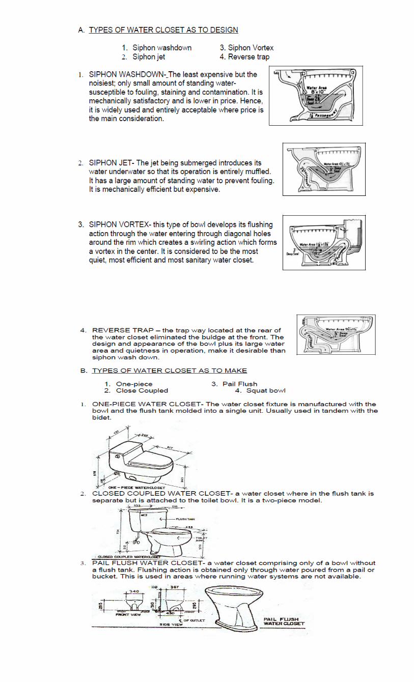
IDENTIFYING WATER CLOSETS
A water closet is a water-flushed plumbing fixture designed to receive and dispose of human waste. The method of flushing can be with either a flush tank or a flushometer valve. Water closets are made of vitreous china, and they can be installed directly on the floor or wall (see Figures 18 and 19).
FIGURE 18. WATER CLOSETS WITH FLUSH TANKS
,
WATER CLOSET
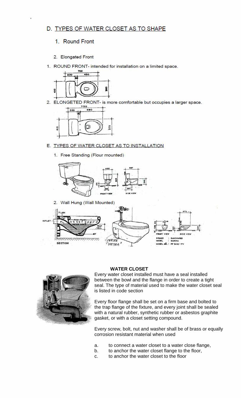
Every water closet installed must have a seal installed between the bowl and the flange in order to create a tight seal. The type of material used to make the water closet seal is listed in code section Every floor flange shall be set on a firm base and bolted to the trap flange of the fixture, and every joint shall be sealed with a natural rubber, synthetic rubber or asbestos graphite gasket, or with a closet setting compound. Every screw, bolt, nut and washer shall be of brass or equally corrosion resistant material when used a. to connect a water closet to a water close flange, b. to anchor the water closet flange to the floor, c. to anchor the water closet to the floor
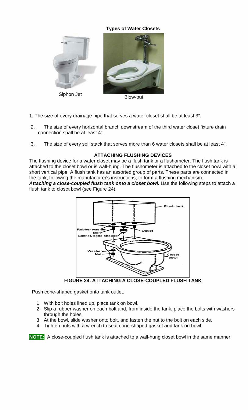
Types of Water Closets
Siphon Jet
Blow-out
1. The size of every drainage pipe that serves a water closet shall be at least 3".
2. The size of every horizontal branch downstream of the third water closet fixture drain connection shall be at least 4".
3. The size of every soil stack that serves more than 6 water closets shall be at least 4".
ATTACHING FLUSHING DEVICES The flushing device for a water closet may be a flush tank or a flushometer. The flush tank is attached to the closet bowl or is wall-hung. The flushometer is attached to the closet bowl with a short vertical pipe. A flush tank has an assorted group of parts. These parts are connected in the tank, following the manufacturer's instructions, to form a flushing mechanism. Attaching a close-coupled flush tank onto a closet bowl. Use the following steps to attach a flush tank to closet bowl (see Figure 24):
FIGURE 24. ATTACHING A CLOSE-COUPLED FLUSH TANK
Push cone-shaped gasket onto tank outlet.
1. With bolt holes lined up, place tank on bowl. 2. Slip a rubber washer on each bolt and, from inside the tank, place the bolts with washers
through the holes. 3. At the bowl, slide washer onto bolt, and fasten the nut to the bolt on each side. 4. Tighten nuts with a wrench to seat cone-shaped gasket and tank on bowl.
NOTE: A close-coupled flush tank is attached to a wall-hung closet bowl in the same manner.
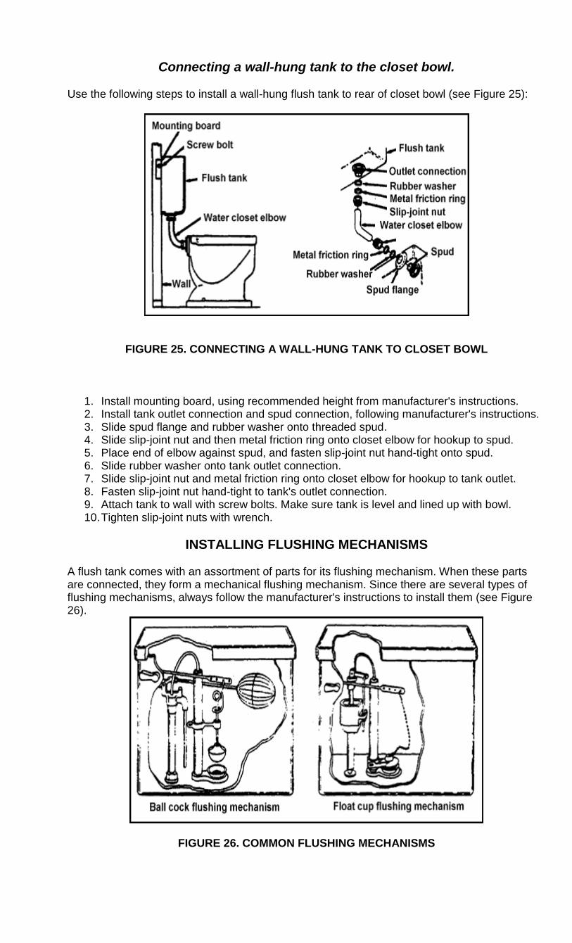
Connecting a wall-hung tank to the closet bowl.
Use the following steps to install a wall-hung flush tank to rear of closet bowl (see Figure 25):
FIGURE 25. CONNECTING A WALL-HUNG TANK TO CLOSET BOWL
1. Install mounting board, using recommended height from manufacturer's instructions. 2. Install tank outlet connection and spud connection, following manufacturer's instructions. 3. Slide spud flange and rubber washer onto threaded spud. 4. Slide slip-joint nut and then metal friction ring onto closet elbow for hookup to spud. 5. Place end of elbow against spud, and fasten slip-joint nut hand-tight onto spud. 6. Slide rubber washer onto tank outlet connection. 7. Slide slip-joint nut and metal friction ring onto closet elbow for hookup to tank outlet. 8. Fasten slip-joint nut hand-tight to tank's outlet connection. 9. Attach tank to wall with screw bolts. Make sure tank is level and lined up with bowl. 10. Tighten slip-joint nuts with wrench.
INSTALLING FLUSHING MECHANISMS
A flush tank comes with an assortment of parts for its flushing mechanism. When these parts are connected, they form a mechanical flushing mechanism. Since there are several types of flushing mechanisms, always follow the manufacturer's instructions to install them (see Figure 26).
FIGURE 26. COMMON FLUSHING MECHANISMS
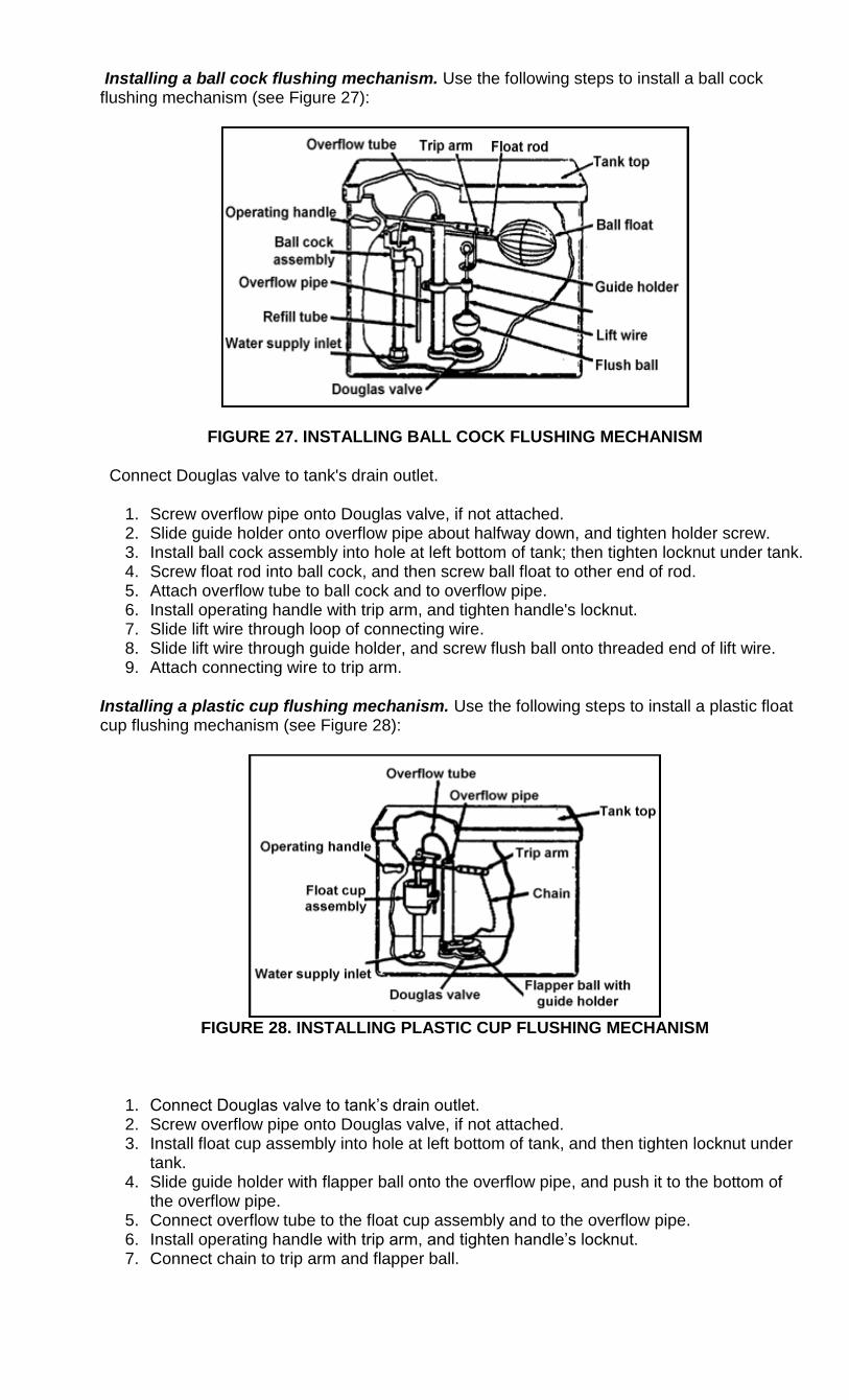
Installing a ball cock flushing mechanism. Use the following steps to install a ball cock flushing mechanism (see Figure 27):
FIGURE 27. INSTALLING BALL COCK FLUSHING MECHANISM
Connect Douglas valve to tank's drain outlet.
1. Screw overflow pipe onto Douglas valve, if not attached. 2. Slide guide holder onto overflow pipe about halfway down, and tighten holder screw. 3. Install ball cock assembly into hole at left bottom of tank; then tighten locknut under tank. 4. Screw float rod into ball cock, and then screw ball float to other end of rod. 5. Attach overflow tube to ball cock and to overflow pipe. 6. Install operating handle with trip arm, and tighten handle's locknut. 7. Slide lift wire through loop of connecting wire. 8. Slide lift wire through guide holder, and screw flush ball onto threaded end of lift wire. 9. Attach connecting wire to trip arm.
Installing a plastic cup flushing mechanism. Use the following steps to install a plastic float cup flushing mechanism (see Figure 28):
FIGURE 28. INSTALLING PLASTIC CUP FLUSHING MECHANISM
1. Connect Douglas valve to tank‘s drain outlet. 2. Screw overflow pipe onto Douglas valve, if not attached. 3. Install float cup assembly into hole at left bottom of tank, and then tighten locknut under
tank. 4. Slide guide holder with flapper ball onto the overflow pipe, and push it to the bottom of
the overflow pipe. 5. Connect overflow tube to the float cup assembly and to the overflow pipe. 6. Install operating handle with trip arm, and tighten handle‘s locknut. 7. Connect chain to trip arm and flapper ball.

INSTALLING FLUSHOMETER
A flushometer is a valve that discharges a preset amount of water to flush a water closet. The flushometer can be either a diaphragm or a piston type of valve. The upper part of the flushometer connected to a water supply line fitting at the wall, and the lower part is connected to the top rear of the water closet bowl (see Figure 29).
FIGURE 29. FLUSHOMETERS
Installing a flushometer. Use the manufacturer's rough-in dimensions and instructions to install a flushometer. Once installed, turn on water supply and adjust flushometer valve's water flow. The following illustrations are examples of manufacturer's rough-in dimensions and instructions (see Figure 30):
FIGURE 30. INSTALLING A FLUSHOMETER
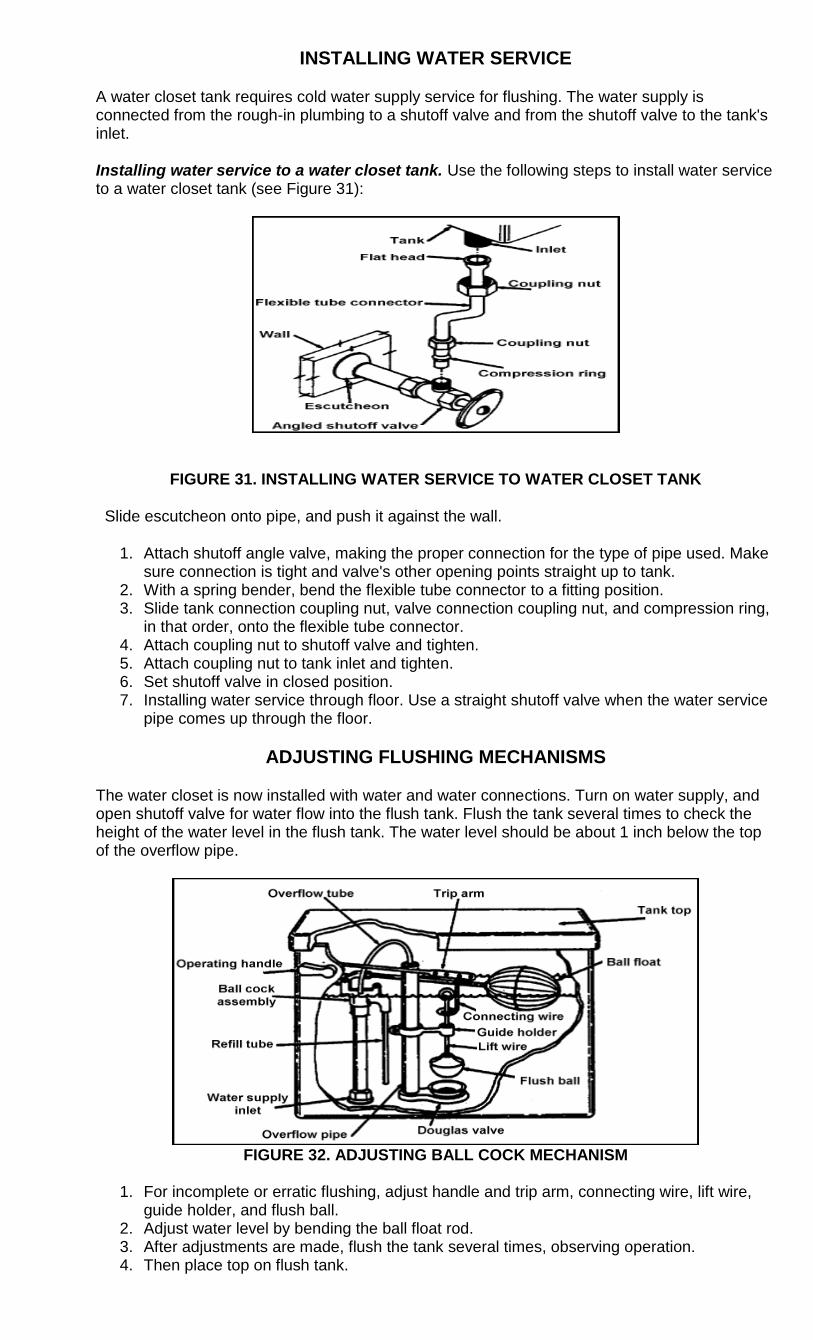
INSTALLING WATER SERVICE
A water closet tank requires cold water supply service for flushing. The water supply is connected from the rough-in plumbing to a shutoff valve and from the shutoff valve to the tank's inlet.
Installing water service to a water closet tank. Use the following steps to install water service to a water closet tank (see Figure 31):
FIGURE 31. INSTALLING WATER SERVICE TO WATER CLOSET TANK
Slide escutcheon onto pipe, and push it against the wall.
1. Attach shutoff angle valve, making the proper connection for the type of pipe used. Make sure connection is tight and valve's other opening points straight up to tank.
2. With a spring bender, bend the flexible tube connector to a fitting position. 3. Slide tank connection coupling nut, valve connection coupling nut, and compression ring,
in that order, onto the flexible tube connector. 4. Attach coupling nut to shutoff valve and tighten. 5. Attach coupling nut to tank inlet and tighten. 6. Set shutoff valve in closed position. 7. Installing water service through floor. Use a straight shutoff valve when the water service
pipe comes up through the floor.
ADJUSTING FLUSHING MECHANISMS
The water closet is now installed with water and water connections. Turn on water supply, and open shutoff valve for water flow into the flush tank. Flush the tank several times to check the height of the water level in the flush tank. The water level should be about 1 inch below the top of the overflow pipe.
FIGURE 32. ADJUSTING BALL COCK MECHANISM
1. For incomplete or erratic flushing, adjust handle and trip arm, connecting wire, lift wire,
guide holder, and flush ball. 2. Adjust water level by bending the ball float rod. 3. After adjustments are made, flush the tank several times, observing operation. 4. Then place top on flush tank.
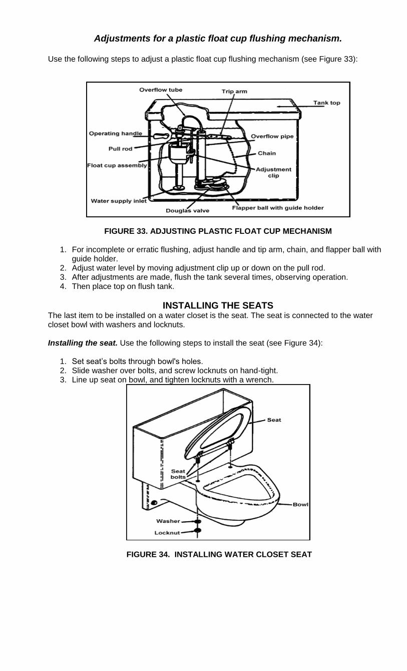
Adjustments for a plastic float cup flushing mechanism.
Use the following steps to adjust a plastic float cup flushing mechanism (see Figure 33):
FIGURE 33. ADJUSTING PLASTIC FLOAT CUP MECHANISM
1. For incomplete or erratic flushing, adjust handle and tip arm, chain, and flapper ball with guide holder.
2. Adjust water level by moving adjustment clip up or down on the pull rod. 3. After adjustments are made, flush the tank several times, observing operation. 4. Then place top on flush tank.
INSTALLING THE SEATS The last item to be installed on a water closet is the seat. The seat is connected to the water closet bowl with washers and locknuts. Installing the seat. Use the following steps to install the seat (see Figure 34):
1. Set seat‘s bolts through bowl's holes. 2. Slide washer over bolts, and screw locknuts on hand-tight. 3. Line up seat on bowl, and tighten locknuts with a wrench.
FIGURE 34. INSTALLING WATER CLOSET SEAT
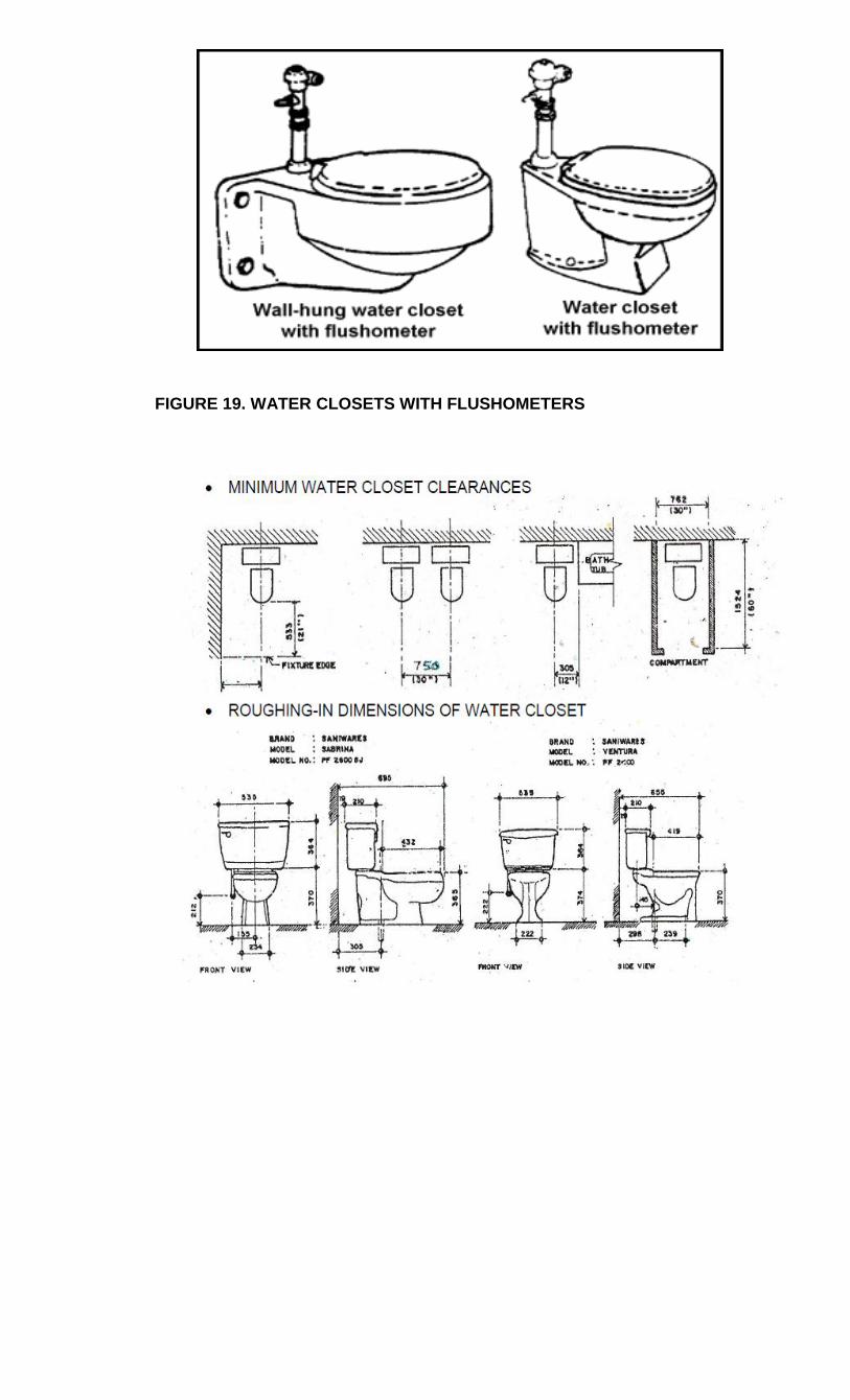
FIGURE 19. WATER CLOSETS WITH FLUSHOMETERS
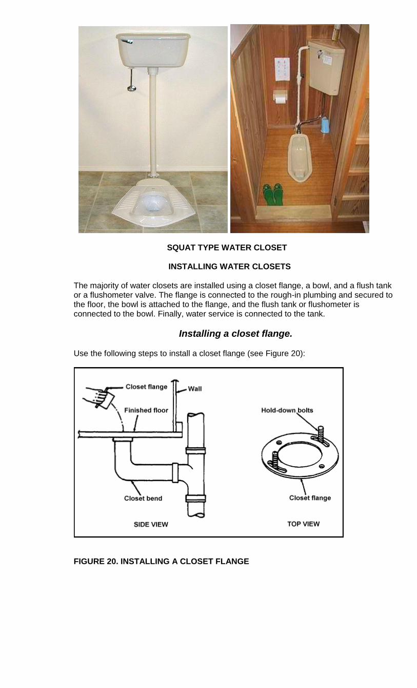
SQUAT TYPE WATER CLOSET
INSTALLING WATER CLOSETS
The majority of water closets are installed using a closet flange, a bowl, and a flush tank or a flushometer valve. The flange is connected to the rough-in plumbing and secured to the floor, the bowl is attached to the flange, and the flush tank or flushometer is connected to the bowl. Finally, water service is connected to the tank.
Installing a closet flange.
Use the following steps to install a closet flange (see Figure 20):
FIGURE 20. INSTALLING A CLOSET FLANGE
LAVATORY
IDENTIFYING LAVATORIES AND SINKS
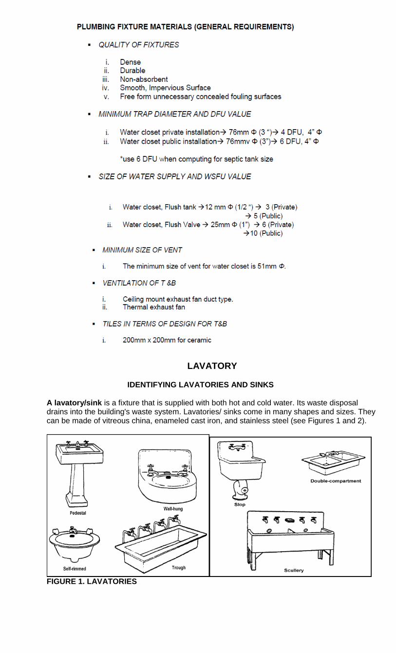
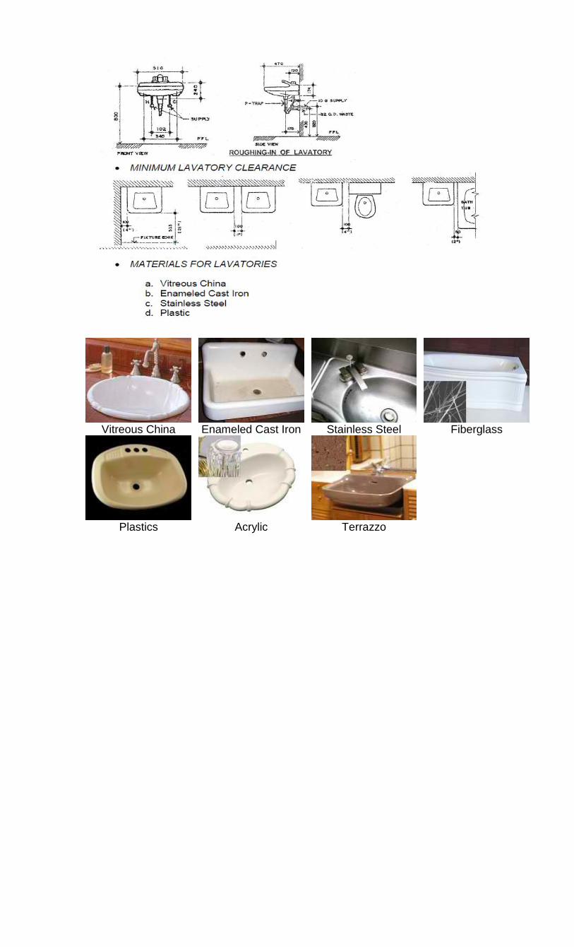
A lavatory/sink is a fixture that is supplied with both hot and cold water. Its waste disposal drains into the building's waste system. Lavatories/ sinks come in many shapes and sizes. They can be made of vitreous china, enameled cast iron, and stainless steel (see Figures 1 and 2).
FIGURE 1. LAVATORIES
Vitreous China
Enameled Cast Iron
Stainless Steel
Fiberglass
Plastics
Acrylic
Terrazzo
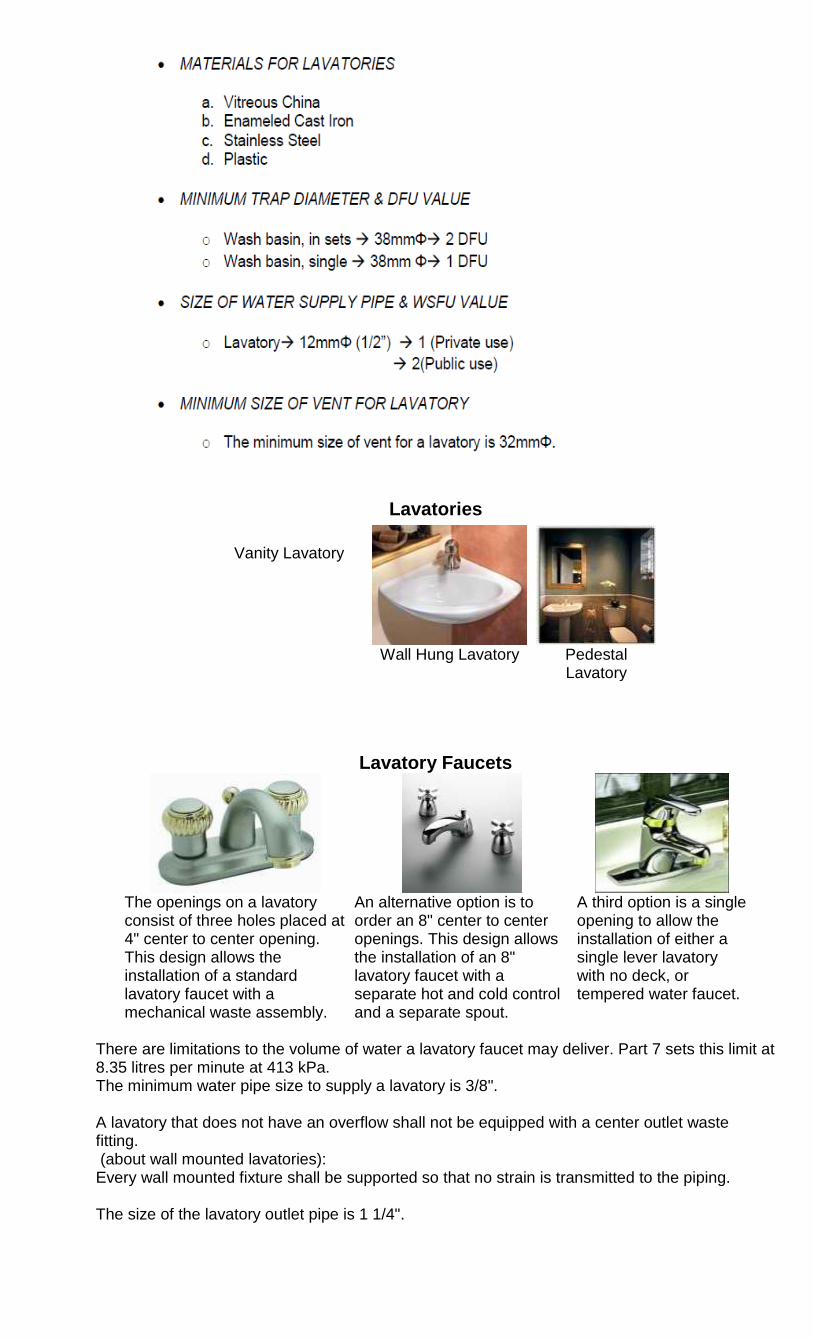
Lavatories
Vanity Lavatory
Wall Hung Lavatory
Pedestal Lavatory
Lavatory Faucets
The openings on a lavatory consist of three holes placed at 4" center to center opening. This design allows the installation of a standard lavatory faucet with a mechanical waste assembly.
An alternative option is to order an 8" center to center openings. This design allows the installation of an 8" lavatory faucet with a separate hot and cold control and a separate spout.
A third option is a single opening to allow the installation of either a single lever lavatory with no deck, or tempered water faucet.
There are limitations to the volume of water a lavatory faucet may deliver. Part 7 sets this limit at 8.35 litres per minute at 413 kPa. The minimum water pipe size to supply a lavatory is 3/8". A lavatory that does not have an overflow shall not be equipped with a center outlet waste fitting. (about wall mounted lavatories): Every wall mounted fixture shall be supported so that no strain is transmitted to the piping. The size of the lavatory outlet pipe is 1 1/4".
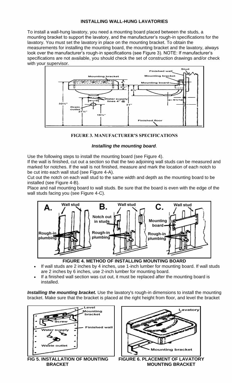
INSTALLING WALL-HUNG LAVATORIES
To install a wall-hung lavatory, you need a mounting board placed between the studs, a mounting bracket to support the lavatory, and the manufacturer‘s rough-in specifications for the lavatory. You must set the lavatory in place on the mounting bracket. To obtain the measurements for installing the mounting board, the mounting bracket and the lavatory, always look over the manufacturer‘s rough-in specifications (see Figure 3). NOTE: If manufacturer‘s specifications are not available, you should check the set of construction drawings and/or check with your supervisor.
FIGURE 3. MANUFACTURER’S SPECIFICATIONS
Installing the mounting board.
Use the following steps to install the mounting board (see Figure 4). If the wall is finished, cut out a section so that the two adjoining wall studs can be measured and marked for notches. If the wall is not finished, measure and mark the location of each notch to be cut into each wall stud (see Figure 4-A). Cut out the notch on each wall stud to the same width and depth as the mounting board to be installed (see Figure 4-B). Place and nail mounting board to wall studs. Be sure that the board is even with the edge of the wall studs facing you (see Figure 4-C).
FIGURE 4. METHOD OF INSTALLING MOUNTING BOARD
If wall studs are 2 inches by 4 inches, use 1-inch lumber for mounting board. If wall studs are 2 inches by 6 inches, use 2-inch lumber for mounting board.
If a finished wall section was cut out, it must be replaced after the mounting board is installed.
Installing the mounting bracket. Use the lavatory's rough-in dimensions to install the mounting bracket. Make sure that the bracket is placed at the right height from floor, and level the bracket
FIG 5. INSTALLATION OF MOUNTING FIGURE 6. PLACEMENT OF LAVATORY BRACKET MOUNTING BRACKET
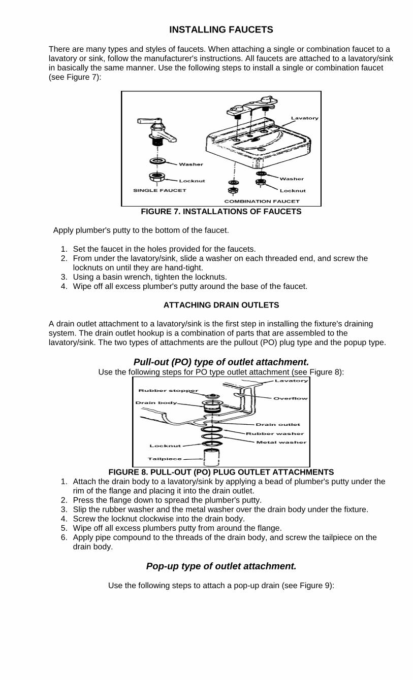
INSTALLING FAUCETS
There are many types and styles of faucets. When attaching a single or combination faucet to a lavatory or sink, follow the manufacturer's instructions. All faucets are attached to a lavatory/sink in basically the same manner. Use the following steps to install a single or combination faucet (see Figure 7):
FIGURE 7. INSTALLATIONS OF FAUCETS
Apply plumber's putty to the bottom of the faucet.
1. Set the faucet in the holes provided for the faucets. 2. From under the lavatory/sink, slide a washer on each threaded end, and screw the
locknuts on until they are hand-tight. 3. Using a basin wrench, tighten the locknuts. 4. Wipe off all excess plumber's putty around the base of the faucet.
ATTACHING DRAIN OUTLETS
A drain outlet attachment to a lavatory/sink is the first step in installing the fixture's draining system. The drain outlet hookup is a combination of parts that are assembled to the lavatory/sink. The two types of attachments are the pullout (PO) plug type and the popup type.
Pull-out (PO) type of outlet attachment. Use the following steps for PO type outlet attachment (see Figure 8):
FIGURE 8. PULL-OUT (PO) PLUG OUTLET ATTACHMENTS
1. Attach the drain body to a lavatory/sink by applying a bead of plumber's putty under the rim of the flange and placing it into the drain outlet.
2. Press the flange down to spread the plumber's putty. 3. Slip the rubber washer and the metal washer over the drain body under the fixture. 4. Screw the locknut clockwise into the drain body. 5. Wipe off all excess plumbers putty from around the flange. 6. Apply pipe compound to the threads of the drain body, and screw the tailpiece on the
drain body.
Pop-up type of outlet attachment.
Use the following steps to attach a pop-up drain (see Figure 9):
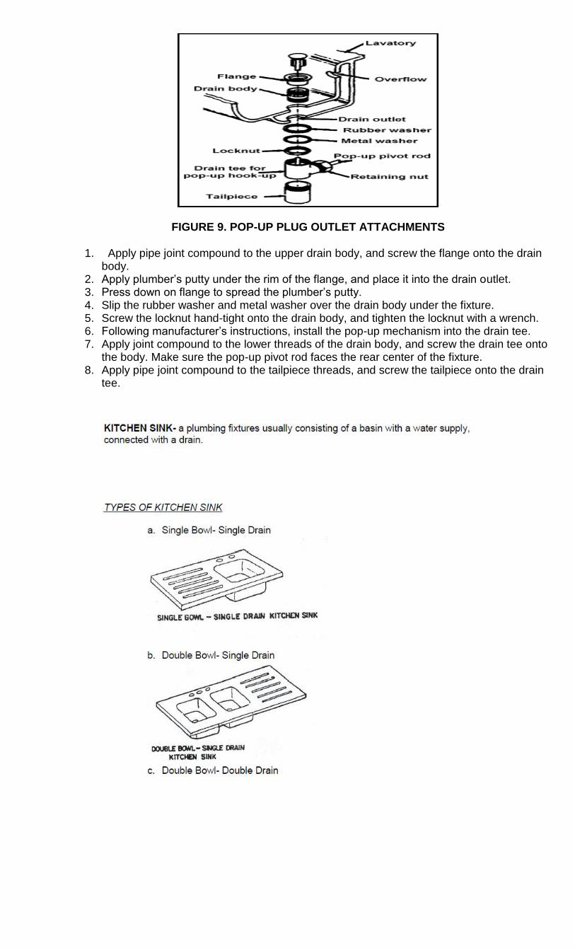
FIGURE 9. POP-UP PLUG OUTLET ATTACHMENTS
1. Apply pipe joint compound to the upper drain body, and screw the flange onto the drain body.
2. Apply plumber‘s putty under the rim of the flange, and place it into the drain outlet. 3. Press down on flange to spread the plumber‘s putty. 4. Slip the rubber washer and metal washer over the drain body under the fixture. 5. Screw the locknut hand-tight onto the drain body, and tighten the locknut with a wrench. 6. Following manufacturer‘s instructions, install the pop-up mechanism into the drain tee. 7. Apply joint compound to the lower threads of the drain body, and screw the drain tee onto
the body. Make sure the pop-up pivot rod faces the rear center of the fixture. 8. Apply pipe joint compound to the tailpiece threads, and screw the tailpiece onto the drain
tee.
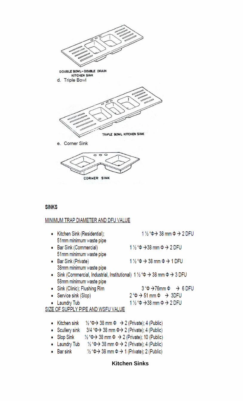
Kitchen Sinks
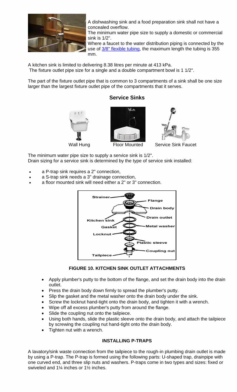
A dishwashing sink and a food preparation sink shall not have a concealed overflow. The minimum water pipe size to supply a domestic or commercial sink is 1/2". Where a faucet to the water distribution piping is connected by the use of 3/8" flexible tubing, the maximum length the tubing is 355 mm.
A kitchen sink is limited to delivering 8.38 litres per minute at 413 kPa. The fixture outlet pipe size for a single and a double compartment bowl is 1 1/2". The part of the fixture outlet pipe that is common to 3 compartments of a sink shall be one size larger than the largest fixture outlet pipe of the compartments that it serves.
Service Sinks
Wall Hung
Floor Mounted
Service Sink Faucet
The minimum water pipe size to supply a service sink is 1/2". Drain sizing for a service sink is determined by the type of service sink installed:
a P-trap sink requires a 2" connection, a S-trap sink needs a 3" drainage connection, a floor mounted sink will need either a 2" or 3" connection.
FIGURE 10. KITCHEN SINK OUTLET ATTACHMENTS
Apply plumber's putty to the bottom of the flange, and set the drain body into the drain outlet.
Press the drain body down firmly to spread the plumber's putty.
Slip the gasket and the metal washer onto the drain body under the sink.
Screw the locknut hand-tight onto the drain body, and tighten it with a wrench.
Wipe off all excess plumber's putty from around the flange.
Slide the coupling nut onto the tailpiece.
Using both hands, slide the plastic sleeve onto the drain body, and attach the tailpiece by screwing the coupling nut hand-tight onto the drain body.
Tighten nut with a wrench.
INSTALLING P-TRAPS
A lavatory/sink waste connection from the tailpiece to the rough-in plumbing drain outlet is made by using a P-trap. The P-trap is formed using the following parts: U-shaped trap, drainpipe with one curved end, and three slip nuts and washers. P-traps come in two types and sizes: fixed or swiveled and 1¼ inches or 1½ inches.
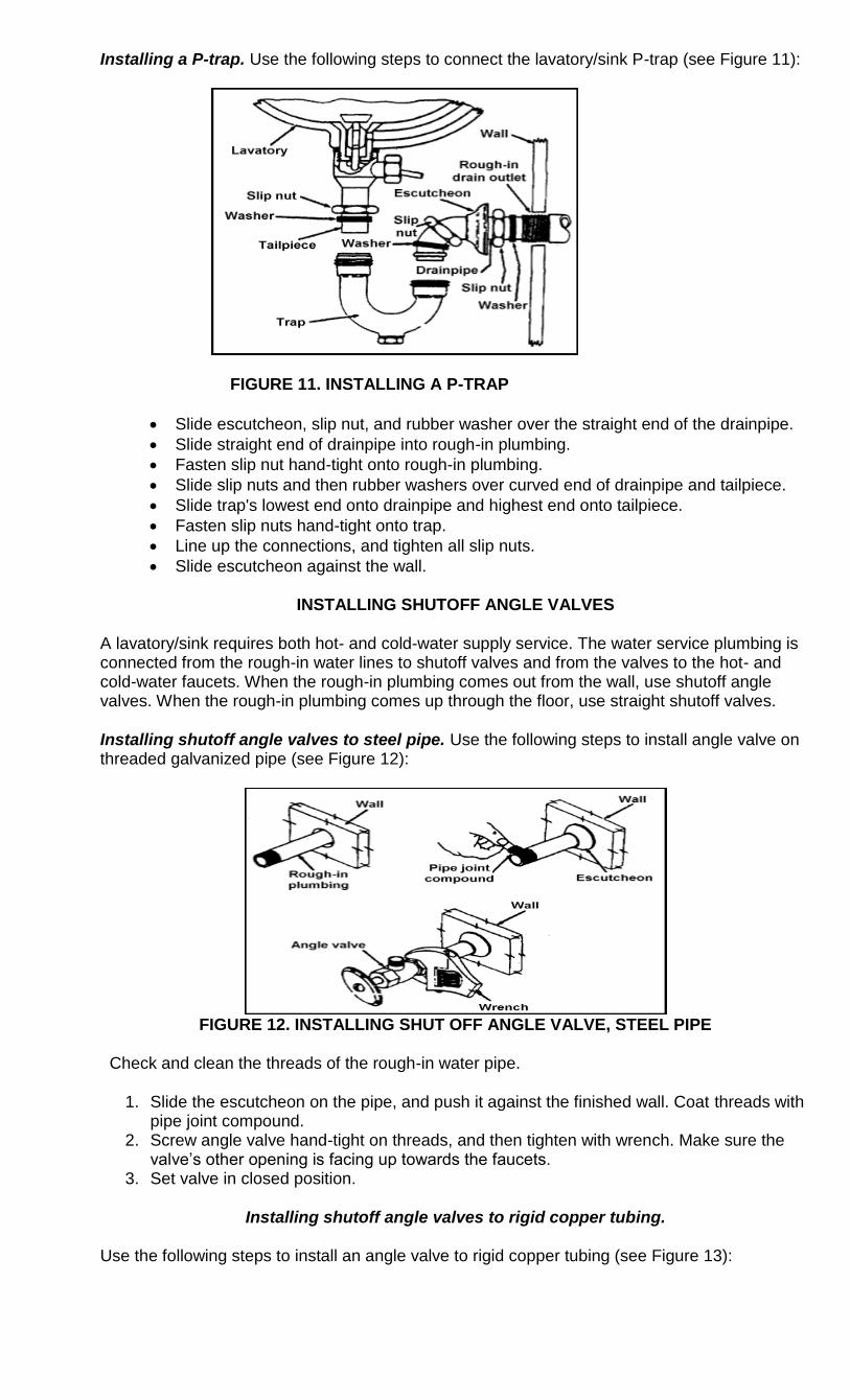
Installing a P-trap. Use the following steps to connect the lavatory/sink P-trap (see Figure 11):
FIGURE 11. INSTALLING A P-TRAP
Slide escutcheon, slip nut, and rubber washer over the straight end of the drainpipe.
Slide straight end of drainpipe into rough-in plumbing.
Fasten slip nut hand-tight onto rough-in plumbing.
Slide slip nuts and then rubber washers over curved end of drainpipe and tailpiece.
Slide trap's lowest end onto drainpipe and highest end onto tailpiece.
Fasten slip nuts hand-tight onto trap.
Line up the connections, and tighten all slip nuts.
Slide escutcheon against the wall.
INSTALLING SHUTOFF ANGLE VALVES
A lavatory/sink requires both hot- and cold-water supply service. The water service plumbing is connected from the rough-in water lines to shutoff valves and from the valves to the hot- and cold-water faucets. When the rough-in plumbing comes out from the wall, use shutoff angle valves. When the rough-in plumbing comes up through the floor, use straight shutoff valves.
Installing shutoff angle valves to steel pipe. Use the following steps to install angle valve on threaded galvanized pipe (see Figure 12):
FIGURE 12. INSTALLING SHUT OFF ANGLE VALVE, STEEL PIPE
Check and clean the threads of the rough-in water pipe.
1. Slide the escutcheon on the pipe, and push it against the finished wall. Coat threads with pipe joint compound.
2. Screw angle valve hand-tight on threads, and then tighten with wrench. Make sure the valve‘s other opening is facing up towards the faucets.
3. Set valve in closed position.
Installing shutoff angle valves to rigid copper tubing.
Use the following steps to install an angle valve to rigid copper tubing (see Figure 13):
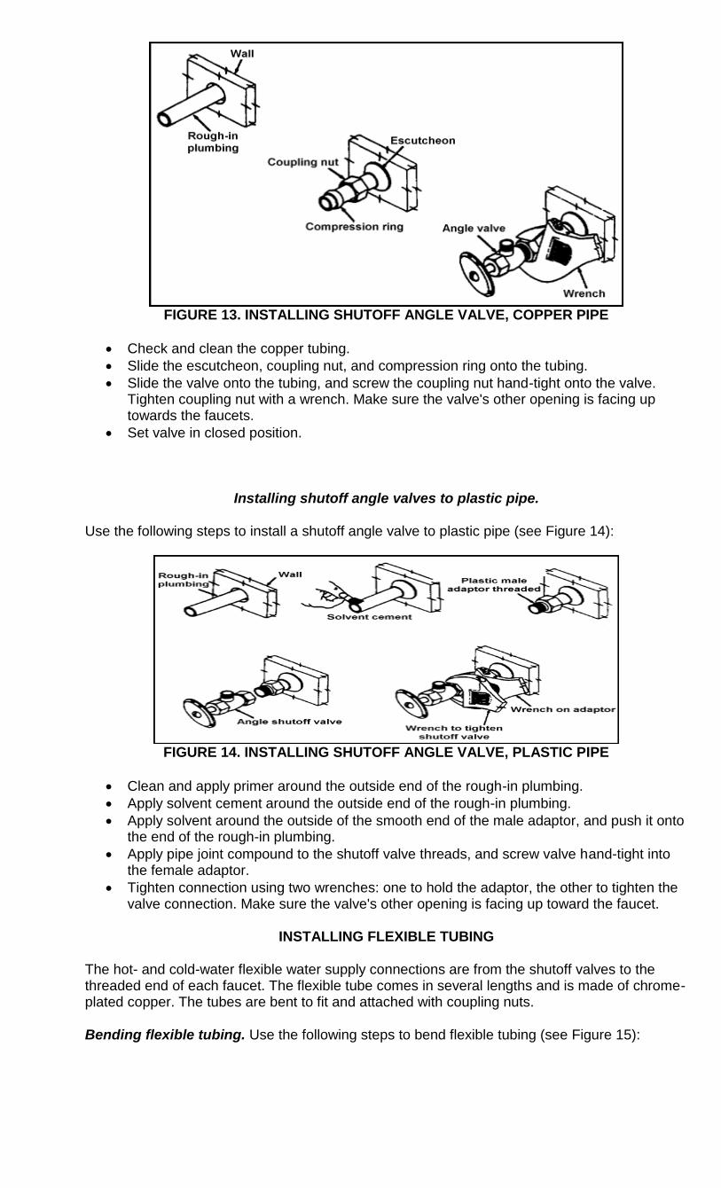
FIGURE 13. INSTALLING SHUTOFF ANGLE VALVE, COPPER PIPE
Check and clean the copper tubing.
Slide the escutcheon, coupling nut, and compression ring onto the tubing.
Slide the valve onto the tubing, and screw the coupling nut hand-tight onto the valve. Tighten coupling nut with a wrench. Make sure the valve's other opening is facing up towards the faucets.
Set valve in closed position.
Installing shutoff angle valves to plastic pipe.
Use the following steps to install a shutoff angle valve to plastic pipe (see Figure 14):
FIGURE 14. INSTALLING SHUTOFF ANGLE VALVE, PLASTIC PIPE
Clean and apply primer around the outside end of the rough-in plumbing.
Apply solvent cement around the outside end of the rough-in plumbing.
Apply solvent around the outside of the smooth end of the male adaptor, and push it onto the end of the rough-in plumbing.
Apply pipe joint compound to the shutoff valve threads, and screw valve hand-tight into the female adaptor.
Tighten connection using two wrenches: one to hold the adaptor, the other to tighten the valve connection. Make sure the valve's other opening is facing up toward the faucet.
INSTALLING FLEXIBLE TUBING
The hot- and cold-water flexible water supply connections are from the shutoff valves to the threaded end of each faucet. The flexible tube comes in several lengths and is made of chrome-plated copper. The tubes are bent to fit and attached with coupling nuts.
Bending flexible tubing. Use the following steps to bend flexible tubing (see Figure 15):
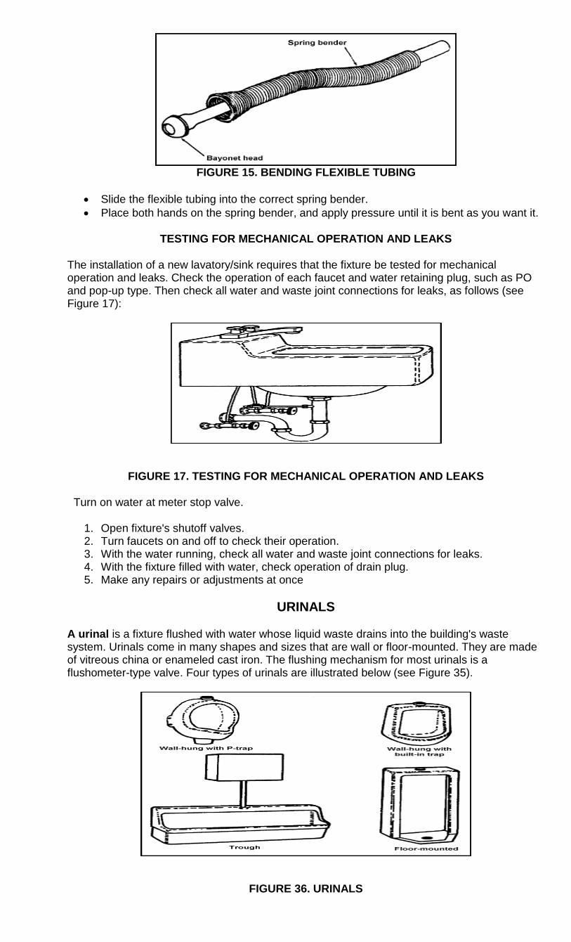
FIGURE 15. BENDING FLEXIBLE TUBING
Slide the flexible tubing into the correct spring bender.
Place both hands on the spring bender, and apply pressure until it is bent as you want it.
TESTING FOR MECHANICAL OPERATION AND LEAKS
The installation of a new lavatory/sink requires that the fixture be tested for mechanical operation and leaks. Check the operation of each faucet and water retaining plug, such as PO and pop-up type. Then check all water and waste joint connections for leaks, as follows (see Figure 17):
FIGURE 17. TESTING FOR MECHANICAL OPERATION AND LEAKS
Turn on water at meter stop valve.
1. Open fixture's shutoff valves. 2. Turn faucets on and off to check their operation. 3. With the water running, check all water and waste joint connections for leaks. 4. With the fixture filled with water, check operation of drain plug. 5. Make any repairs or adjustments at once
URINALS
A urinal is a fixture flushed with water whose liquid waste drains into the building's waste system. Urinals come in many shapes and sizes that are wall or floor-mounted. They are made of vitreous china or enameled cast iron. The flushing mechanism for most urinals is a flushometer-type valve. Four types of urinals are illustrated below (see Figure 35).
FIGURE 36. URINALS
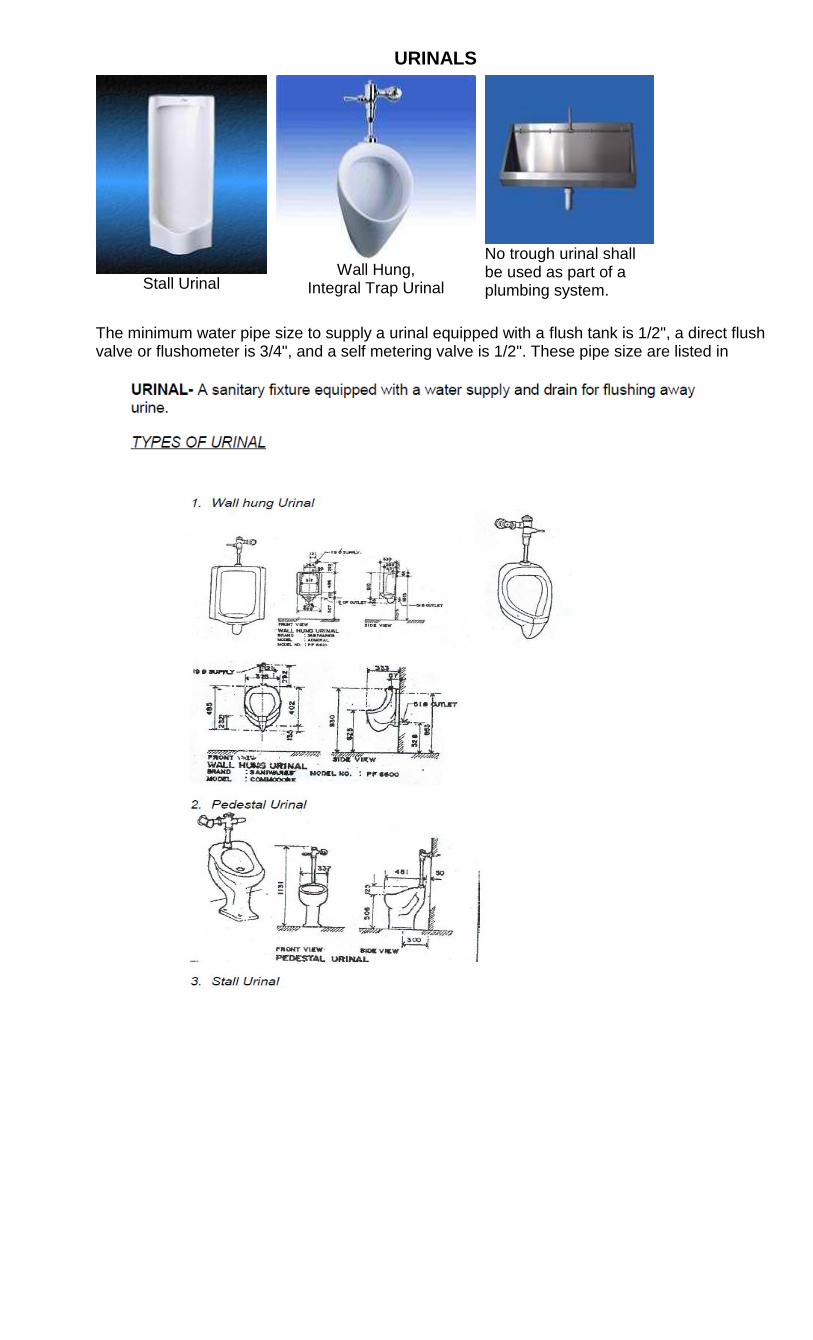
URINALS
Stall Urinal
Wall Hung,
Integral Trap Urinal
No trough urinal shall be used as part of a plumbing system.
The minimum water pipe size to supply a urinal equipped with a flush tank is 1/2", a direct flush valve or flushometer is 3/4", and a self metering valve is 1/2". These pipe size are listed in
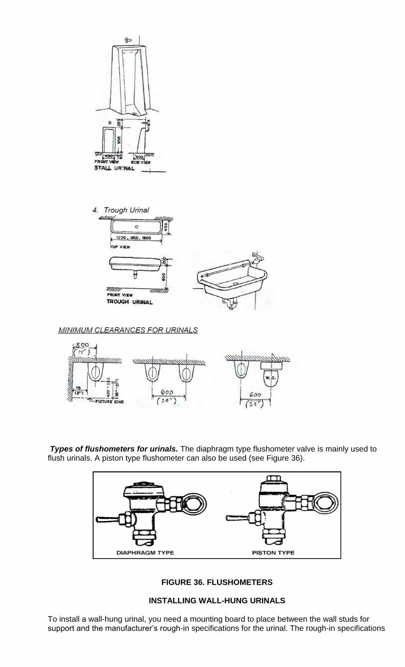
Types of flushometers for urinals. The diaphragm type flushometer valve is mainly used to flush urinals. A piston type flushometer can also be used (see Figure 36).
FIGURE 36. FLUSHOMETERS
INSTALLING WALL-HUNG URINALS
To install a wall-hung urinal, you need a mounting board to place between the wall studs for support and the manufacturer‘s rough-in specifications for the urinal. The rough-in specifications
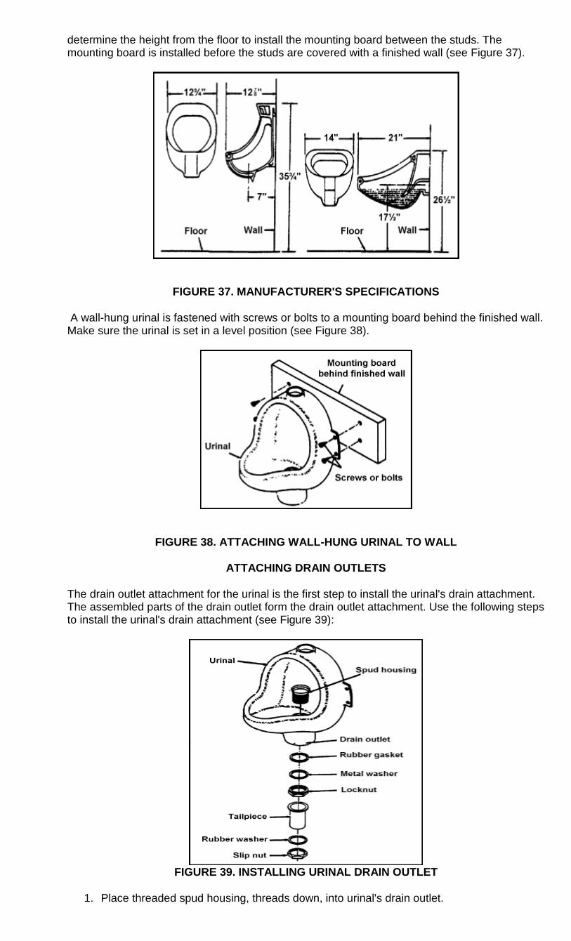
determine the height from the floor to install the mounting board between the studs. The mounting board is installed before the studs are covered with a finished wall (see Figure 37).
FIGURE 37. MANUFACTURER'S SPECIFICATIONS
A wall-hung urinal is fastened with screws or bolts to a mounting board behind the finished wall. Make sure the urinal is set in a level position (see Figure 38).
FIGURE 38. ATTACHING WALL-HUNG URINAL TO WALL
ATTACHING DRAIN OUTLETS
The drain outlet attachment for the urinal is the first step to install the urinal's drain attachment. The assembled parts of the drain outlet form the drain outlet attachment. Use the following steps to install the urinal's drain attachment (see Figure 39):
FIGURE 39. INSTALLING URINAL DRAIN OUTLET
1. Place threaded spud housing, threads down, into urinal's drain outlet.
2. Slide rubber gasket onto spud housing through the drain outlet. 3. Slide metal washer onto spud housing. 4. Screw locknut onto spud housing, and tighten with a wrench. 5. Slide rubber washer, and then slip nut onto tailpiece. 6. Place tailpiece against spud housing, and screw slip nut hand-tight onto spud housing. 7. Tighten slip nut with a wrench.
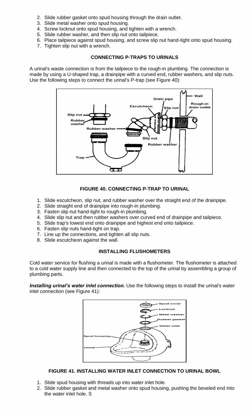
CONNECTING P-TRAPS TO URINALS
A urinal's waste connection is from the tailpiece to the rough-in plumbing. The connection is made by using a U-shaped trap, a drainpipe with a curved end, rubber washers, and slip nuts. Use the following steps to connect the urinal's P-trap (see Figure 40):
FIGURE 40. CONNECTING P-TRAP TO URINAL
1. Slide escutcheon, slip nut, and rubber washer over the straight end of the drainpipe. 2. Slide straight end of drainpipe into rough-in plumbing. 3. Fasten slip nut hand-tight to rough-in plumbing. 4. Slide slip nut and then rubber washers over curved end of drainpipe and tailpiece. 5. Slide trap's lowest end onto drainpipe and highest end onto tailpiece. 6. Fasten slip nuts hand-tight on trap. 7. Line up the connections, and tighten all slip nuts. 8. Slide escutcheon against the wall.
INSTALLING FLUSHOMETERS
Cold water service for flushing a urinal is made with a flushometer. The flushometer is attached to a cold water supply line and then connected to the top of the urinal by assembling a group of plumbing parts.
Installing urinal’s water inlet connection. Use the following steps to install the urinal's water inlet connection (see Figure 41):
FIGURE 41. INSTALLING WATER INLET CONNECTION TO URINAL BOWL
1. Slide spud housing with threads up into water inlet hole. 2. Slide rubber gasket and metal washer onto spud housing, pushing the beveled end into
the water inlet hole. S
3. crew locknut onto spud housing, and tighten nut. 4. Slide cover over threads of spud housing.
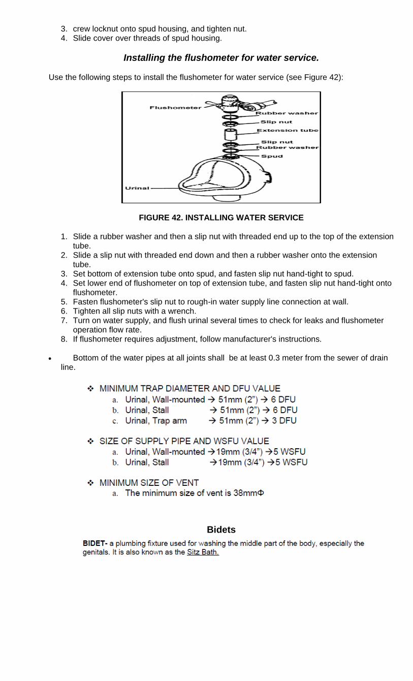
Installing the flushometer for water service.
Use the following steps to install the flushometer for water service (see Figure 42):
FIGURE 42. INSTALLING WATER SERVICE
1. Slide a rubber washer and then a slip nut with threaded end up to the top of the extension tube.
2. Slide a slip nut with threaded end down and then a rubber washer onto the extension tube.
3. Set bottom of extension tube onto spud, and fasten slip nut hand-tight to spud. 4. Set lower end of flushometer on top of extension tube, and fasten slip nut hand-tight onto
flushometer. 5. Fasten flushometer's slip nut to rough-in water supply line connection at wall. 6. Tighten all slip nuts with a wrench. 7. Turn on water supply, and flush urinal several times to check for leaks and flushometer
operation flow rate. 8. If flushometer requires adjustment, follow manufacturer's instructions.
Bottom of the water pipes at all joints shall be at least 0.3 meter from the sewer of drain line.
Bidets
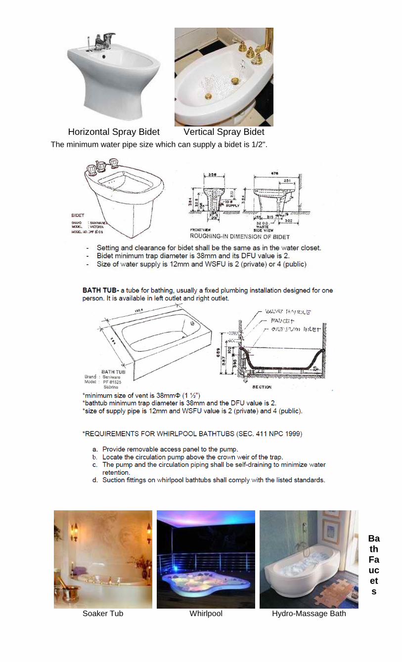
Horizontal Spray Bidet
Vertical Spray Bidet
The minimum water pipe size which can supply a bidet is 1/2".
Bath Faucets
Soaker Tub
Whirlpool
Hydro-Massage Bath
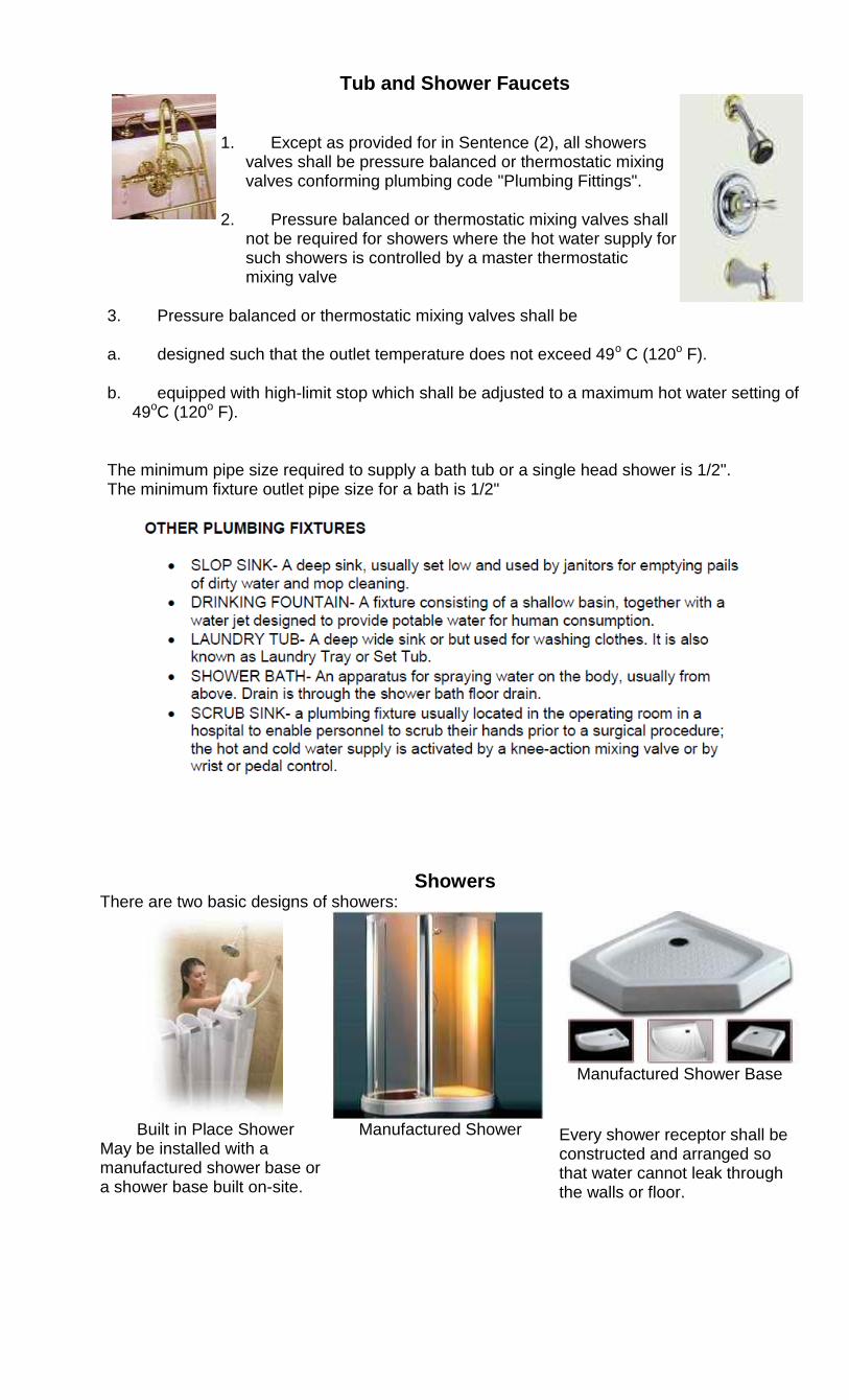
Tub and Shower Faucets
1. Except as provided for in Sentence (2), all showers valves shall be pressure balanced or thermostatic mixing valves conforming plumbing code "Plumbing Fittings".
2. Pressure balanced or thermostatic mixing valves shall not be required for showers where the hot water supply for such showers is controlled by a master thermostatic mixing valve
3. Pressure balanced or thermostatic mixing valves shall be
a. designed such that the outlet temperature does not exceed 49o C (120o F).
b. equipped with high-limit stop which shall be adjusted to a maximum hot water setting of 49oC (120o F).
The minimum pipe size required to supply a bath tub or a single head shower is 1/2". The minimum fixture outlet pipe size for a bath is 1/2"
Showers There are two basic designs of showers:
Built in Place Shower
May be installed with a manufactured shower base or a shower base built on-site.
Manufactured Shower
Manufactured Shower Base
Every shower receptor shall be constructed and arranged so that water cannot leak through the walls or floor.
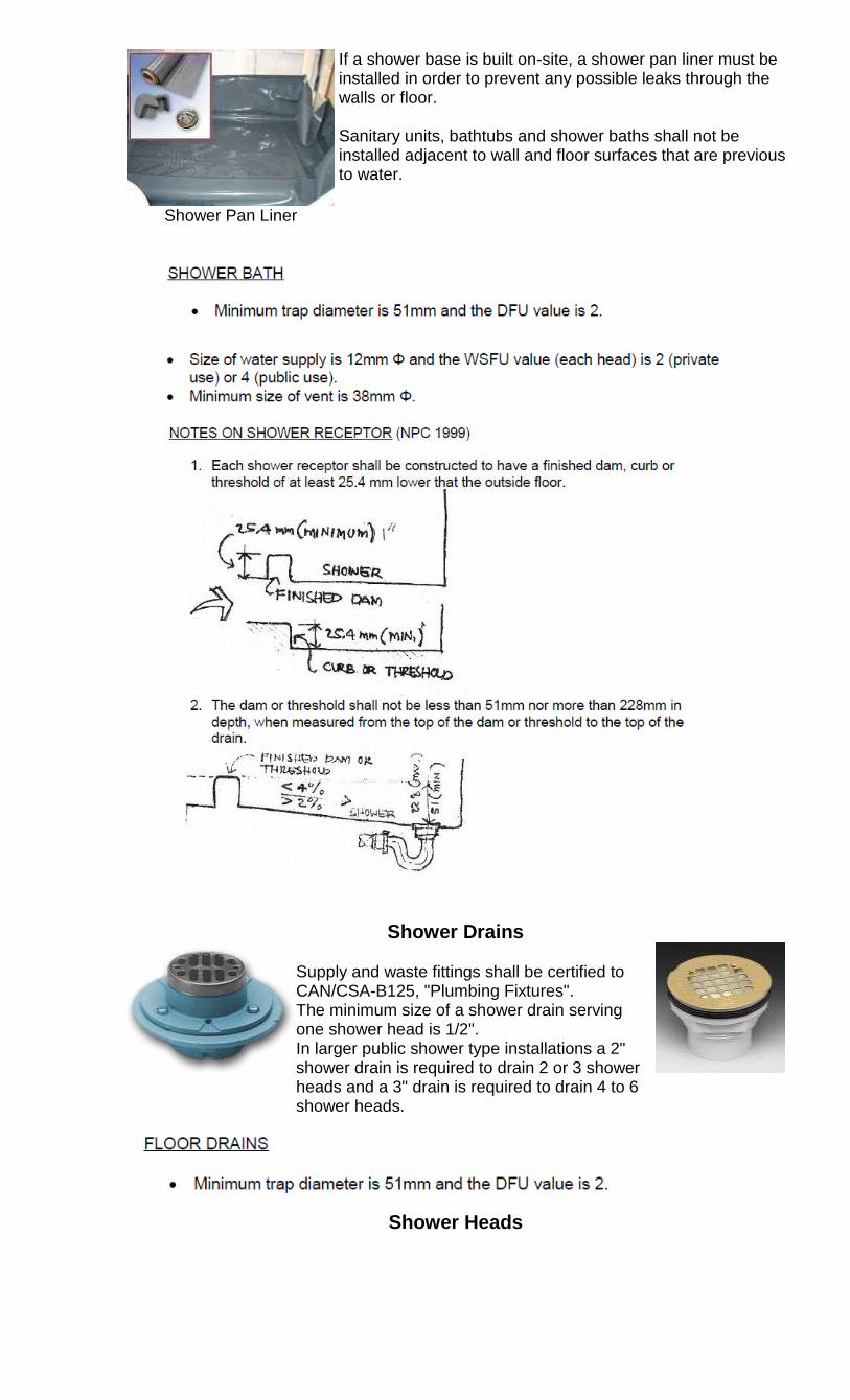
Shower Pan Liner
If a shower base is built on-site, a shower pan liner must be installed in order to prevent any possible leaks through the walls or floor. Sanitary units, bathtubs and shower baths shall not be installed adjacent to wall and floor surfaces that are previous to water.
Shower Drains
Supply and waste fittings shall be certified to CAN/CSA-B125, "Plumbing Fixtures". The minimum size of a shower drain serving one shower head is 1/2". In larger public shower type installations a 2" shower drain is required to drain 2 or 3 shower heads and a 3" drain is required to drain 4 to 6 shower heads.
Shower Heads
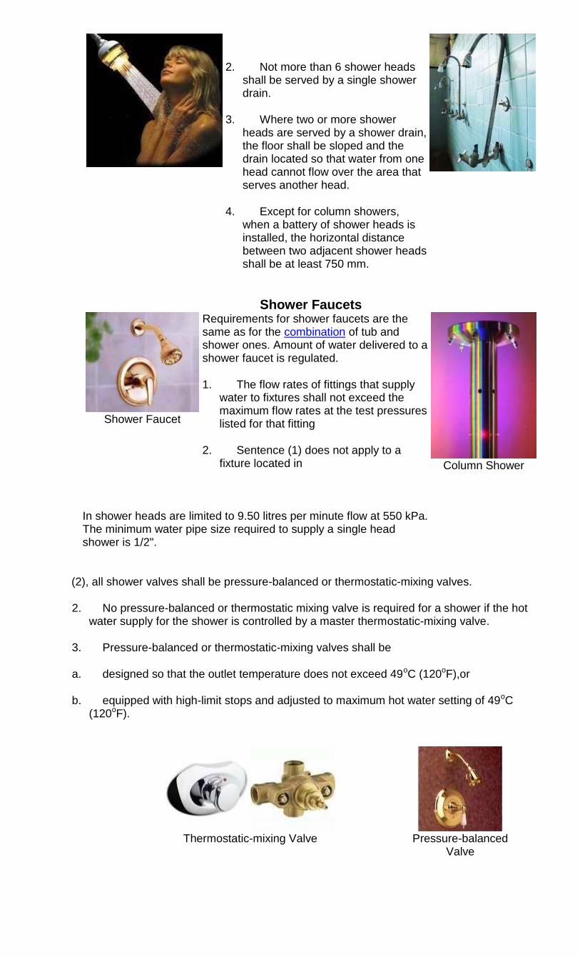
2. Not more than 6 shower heads shall be served by a single shower drain.
3. Where two or more shower heads are served by a shower drain, the floor shall be sloped and the drain located so that water from one head cannot flow over the area that serves another head.
4. Except for column showers, when a battery of shower heads is installed, the horizontal distance between two adjacent shower heads shall be at least 750 mm.
Shower Faucets
Shower Faucet
Requirements for shower faucets are the same as for the combination of tub and shower ones. Amount of water delivered to a shower faucet is regulated.
1. The flow rates of fittings that supply water to fixtures shall not exceed the maximum flow rates at the test pressures listed for that fitting
2. Sentence (1) does not apply to a fixture located in
Column Shower
In shower heads are limited to 9.50 litres per minute flow at 550 kPa. The minimum water pipe size required to supply a single head shower is 1/2".
(2), all shower valves shall be pressure-balanced or thermostatic-mixing valves.
2. No pressure-balanced or thermostatic mixing valve is required for a shower if the hot water supply for the shower is controlled by a master thermostatic-mixing valve.
3. Pressure-balanced or thermostatic-mixing valves shall be
a. designed so that the outlet temperature does not exceed 49oC (120oF),or
b. equipped with high-limit stops and adjusted to maximum hot water setting of 49oC (120oF).
Thermostatic-mixing Valve Pressure-balanced Valve
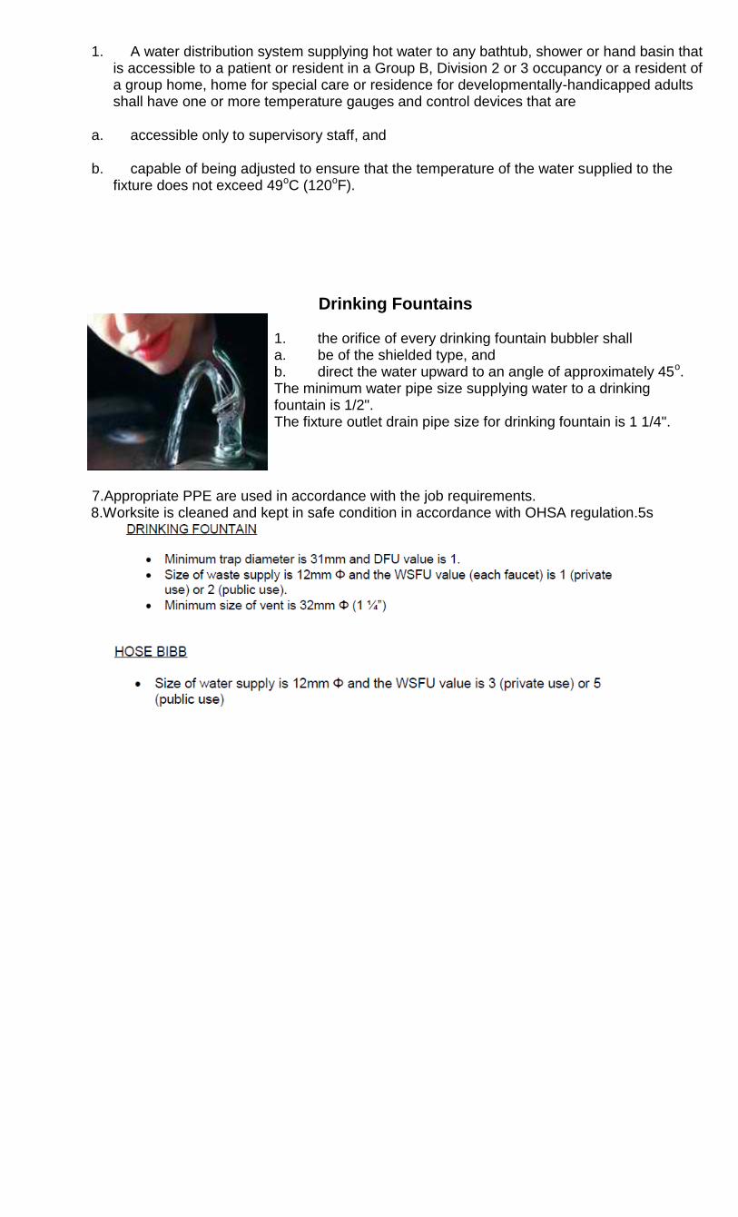
1. A water distribution system supplying hot water to any bathtub, shower or hand basin that is accessible to a patient or resident in a Group B, Division 2 or 3 occupancy or a resident of a group home, home for special care or residence for developmentally-handicapped adults shall have one or more temperature gauges and control devices that are
a. accessible only to supervisory staff, and
b. capable of being adjusted to ensure that the temperature of the water supplied to the fixture does not exceed 49oC (120oF).
Drinking Fountains
1. the orifice of every drinking fountain bubbler shall a. be of the shielded type, and b. direct the water upward to an angle of approximately 45o. The minimum water pipe size supplying water to a drinking fountain is 1/2". The fixture outlet drain pipe size for drinking fountain is 1 1/4".
7.Appropriate PPE are used in accordance with the job requirements.
8.Worksite is cleaned and kept in safe condition in accordance with OHSA regulation.5s
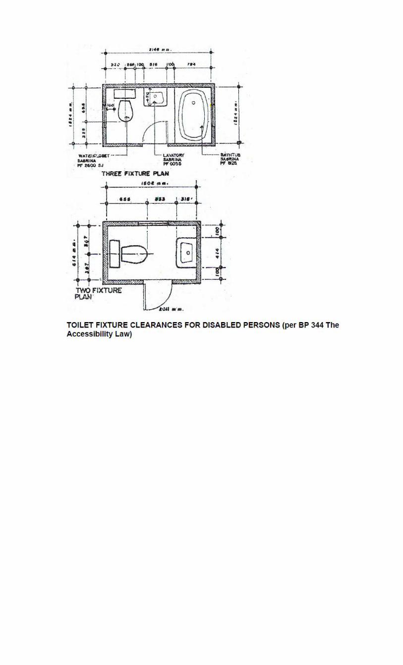
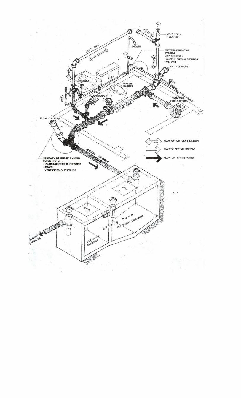
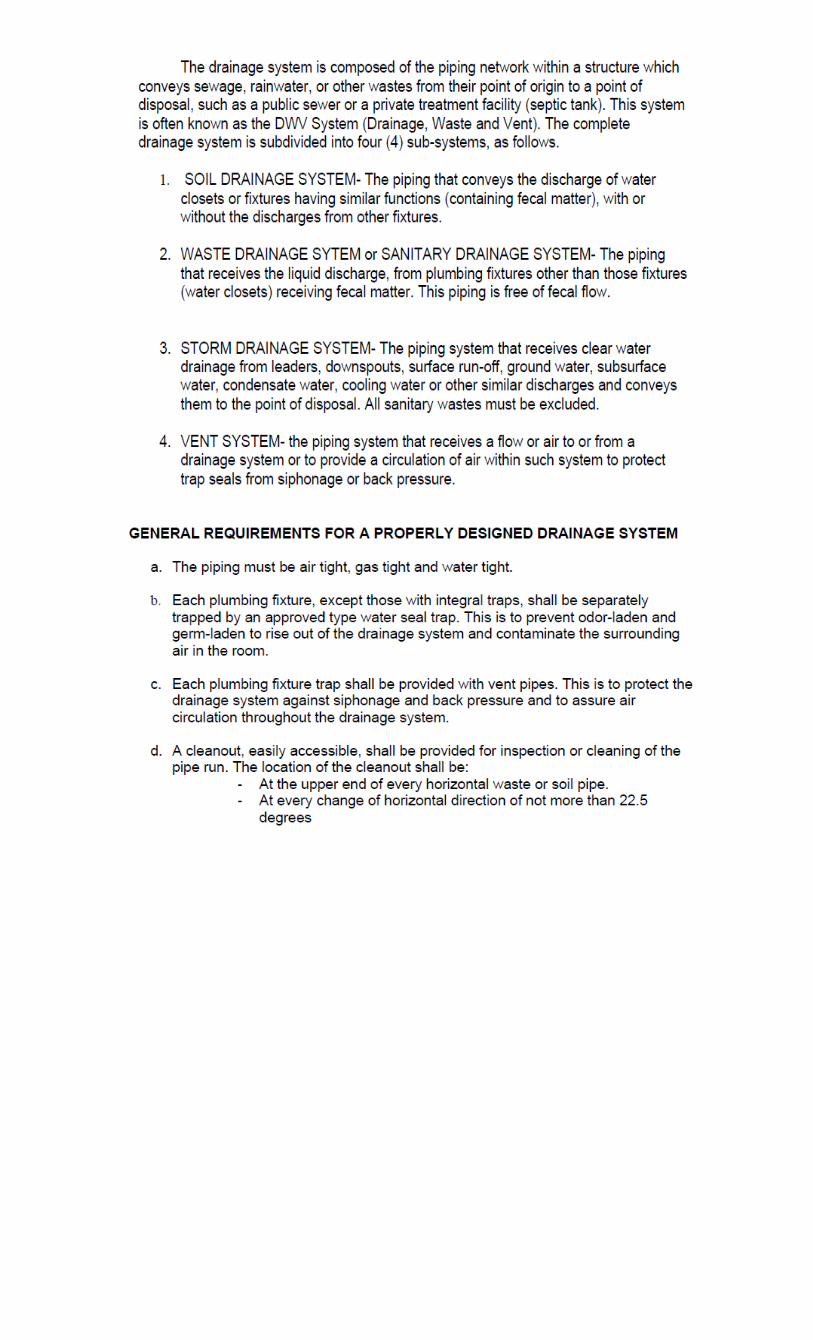
DRAINAGE SYSTEM
UNIT OF COMPETENCY:PERFORM PLUMBING REPAIR AND MAINTENANCE WORKS MODULE TITLE : Performing plumbing repair works MODULE DESCRIPTOR : This module covers the knowledge, skills and attitudes in
repairing plumbing works &-painting and/or re-touching mating
SUMMARY OF LEARNING OUTCOMES: L O 1. Repair defective pipes and fittings
L O 2. Repair defective plumbing fixtures and accessories
L O 1. REPAIR DEFECTIVE PIPES AND FITTINGS Assessment Criteria:
1. Defective pipes and fittings are located, identified and repaired as is where is.
Mensuration
Materials use and specification 2. Replacement pipes and/or fittings are checked to ensure they are free from defects and
in accordance with standard specifications or as required.
Knowledge of plumbing work 3. Joints are tightly secured and leak-free in accordance with the job requirements. 4. Damage areas are restored or repaired in line with standard operating procedures. 5. Correct usage of tools and equipments is observed in accordance with job requirements.
Proper use of drawing tools/equipment 6. Appropriate PPE are used in accordance with job requirements.
Safety precautions and 5 S implementation
L O 2. REPAIR DEFECTIVE PLUMBING FIXTURES AND ACCESSORIES Assessment Criteria:
1. Defective plumbing fixtures repaired and/or replaced 2. Replacement plumbing fixtures are checked to ensure they are free from defects and
in accordance with standard specification or as required.
Repair and replace plumbing fixtures
Replacement of fittings for plumbing fixtures
Bathroom Fixtures: Repair or Replaced?
To fix or not to fix? That is the question when it comes to a leaky toilet, a cracked sink, or a stained tub. Bathroom fixtures can be pricey to replace, so it makes sense to research repair options before you rush out and buy a new one. Then again, sometimes those lavatory troubles aren‘t worth fixing—only a new fixture will do. Here‘s how to figure out the best option for you: TOILET. If your toilet is clogged, running constantly, or leaking, opt for repairs before you look for a new model. Toilet repairs are often friendly and can be taken care of in a relatively short period of time. Have a broken flush handle? Replaced. . If your toilet tank is cracked, however you‘ll need to buy a new tank. And in some cases, a constant leak means the toilet base is cracked and needs replaced. In either instance, unless your toilet is relatively new, it‘s probably smart to buy a new toilet—today‘s models are much more efficient anyway, so you‘ll likely end up saving in the long run on reduced water bills. SINK and FAUCET. If your leaky sink originates from the plumbing beneath the sink or the faucet, you can likely tackle repairs depending on the severity of a problem. Learn how to repair a faucet or leaky pipes in no time. A clogged drain might be a problem too—in that case, here‘s what to do . Or, when it‘s time, you can replace the faucet yourself. If your sink is cracked (which can occur pretty easily with a porcelain sink), you won‘t be able to fix it—but you can replace it yourself.
Tub. If your bathroom woes originate from your tub, first check out the pointers offered at Home Tips, which cover fast fixes for porcelain rust (hint: try lemon juice and salt!), faulty pop-up bathtub stoppers, fiberglass bathtub scratches, and more. If a leaky or damaged bathtub spout is the problem, . Or if scratches or chips are a problem, before you buy a replacement you might want to consider bathtub refinishing, a project that can be done to a damaged porcelain, fiberglass, or cast-iron tub on your own or by a pro. It involves priming, sealing, and painting your tub with a durable, glossy top-coat.
3. Joints are tightly secured and leak free in accordance with the job requirements 4. Damage areas are restored or repaired in line with standard operating procedures. 5. Correct usage of tools and equipment is observed in accordance with job
requirements. 6. Appropriate PPE are used in accordance with job requirements.
UNIT OF COMPETENCY : PERFORM PLUMBING REPAIR AND MAINTENANCE WORKS MODULE TITLE : Performing plumbing maintenance MODULE DESCRIPTOR : This module covers the knowledge, skills and attitudes in
maintaining plumbing works.; performing painting works, mixing/tinting of paints, s.
NOMINAL DURATION : 20 Hrs. SUMMARY OF LEARNING OUTCOMES: L O 1. Clear clogged pipes
L O 2. Clear clogged fixtures L O 1. CLEAR CLOGGED PIPES
Assessment Criteria: 1. Clogged pipes are correctly located in line with approved working plan. 2. Clogged pipes are cleared using appropriate method.
procedure in cleaning clog pipes 3. Pipes are cleared and provided with screen in line with standard operating procedures. 4. Appropriate PPE are used in accordance with the job requirements.
PPE
5S
L O 2. CLEARED CLOGGED FIXTURES Assessment Criteria:
1. Clogged fixture drains are correctly located in line with approved working plan. 2. Clogged fixture drains are cleared using appropriate method. 3. Fixture drains are cleared and provided with screen in line with standard operating
procedures.
Procedure in cleaning fixtures drains 4. Appropriate PPE are used in accordance with the job requirements.
PPE
5S
Guide to Easy Step by Step Methods to Clear a Clogged Building Drain
A clogged plumbing fixture is common trouble - here we give some easy procedures to de-clog a sink, tub, shower, toilet, etc.
Watch out: if your building drains into a private septic system, clogged or slow drains can be a sign of septic system trouble. In that case, still the problem can be as simple as a clogged drain, or unfortunately it can be as costly as a failed septic leach field or soakaway bed. Here we include diagnostic steps to figure out what's wrong.
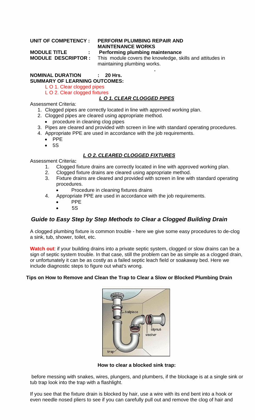
Tips on How to Remove and Clean the Trap to Clear a Slow or Blocked Plumbing Drain
How to clear a blocked sink trap:
before messing with snakes, wires, plungers, and plumbers, if the blockage is at a single sink or tub trap look into the trap with a flashlight. If you see that the fixture drain is blocked by hair, use a wire with its end bent into a hook or even needle nosed pliers to see if you can carefully pull out and remove the clog of hair and
crud yourself. While you're there under the sink, if the fixture trap is corroded, leaky, or damaged, put a bucket under it to catch water, disassemble it, and take the parts to your local hardware store to simply buy a replacement. Be careful to avoid bending or damaging the sink tailpiece or the horizontal connecting pipe at the building wall or you'll end up having to replace those as well.
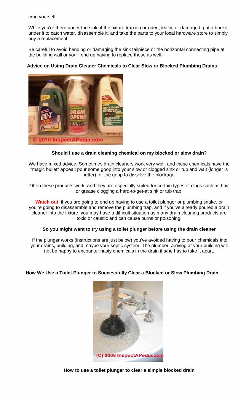
Advice on Using Drain Cleaner Chemicals to Clear Slow or Blocked Plumbing Drains
Should I use a drain cleaning chemical on my blocked or slow drain?
We have mixed advice. Sometimes drain cleaners work very well, and these chemicals have the "magic bullet" appeal: pour some goop into your slow or clogged sink or tub and wait (longer is
better) for the goop to dissolve the blockage.
Often these products work, and they are especially suited for certain types of clogs such as hair or grease clogging a hard-to-get-at sink or tub trap.
Watch out: if you are going to end up having to use a toilet plunger or plumbing snake, or
you're going to disassemble and remove the plumbing trap, and if you've already poured a drain cleaner into the fixture, you may have a difficult situation as many drain cleaning products are
toxic or caustic and can cause burns or poisoning.
So you might want to try using a toilet plunger before using the drain cleaner
If the plunger works (instructions are just below) you've avoided having to pour chemicals into your drains, building, and maybe your septic system. The plumber, arriving at your building will
not be happy to encounter nasty chemicals in the drain if s/he has to take it apart.
How We Use a Toilet Plunger to Successfully Clear a Blocked or Slow Plumbing Drain
How to use a toilet plunger to clear a simple blocked drain
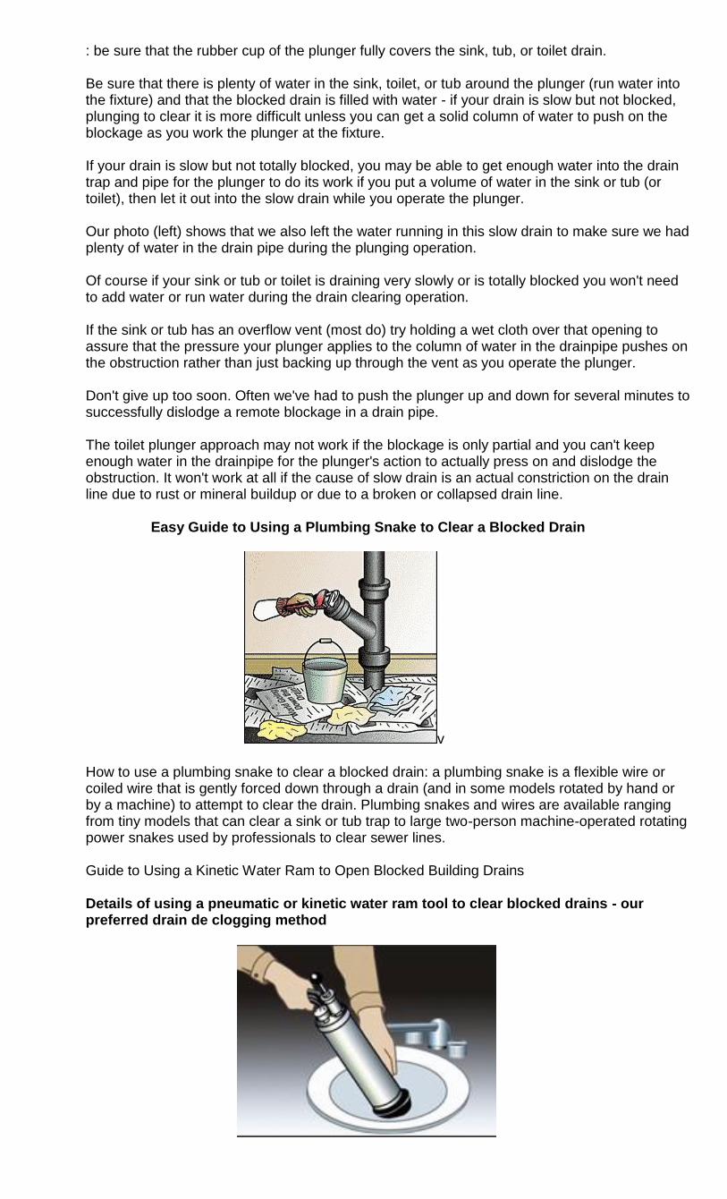
: be sure that the rubber cup of the plunger fully covers the sink, tub, or toilet drain. Be sure that there is plenty of water in the sink, toilet, or tub around the plunger (run water into the fixture) and that the blocked drain is filled with water - if your drain is slow but not blocked, plunging to clear it is more difficult unless you can get a solid column of water to push on the blockage as you work the plunger at the fixture. If your drain is slow but not totally blocked, you may be able to get enough water into the drain trap and pipe for the plunger to do its work if you put a volume of water in the sink or tub (or toilet), then let it out into the slow drain while you operate the plunger. Our photo (left) shows that we also left the water running in this slow drain to make sure we had plenty of water in the drain pipe during the plunging operation. Of course if your sink or tub or toilet is draining very slowly or is totally blocked you won't need to add water or run water during the drain clearing operation. If the sink or tub has an overflow vent (most do) try holding a wet cloth over that opening to assure that the pressure your plunger applies to the column of water in the drainpipe pushes on the obstruction rather than just backing up through the vent as you operate the plunger. Don't give up too soon. Often we've had to push the plunger up and down for several minutes to successfully dislodge a remote blockage in a drain pipe. The toilet plunger approach may not work if the blockage is only partial and you can't keep enough water in the drainpipe for the plunger's action to actually press on and dislodge the obstruction. It won't work at all if the cause of slow drain is an actual constriction on the drain line due to rust or mineral buildup or due to a broken or collapsed drain line.
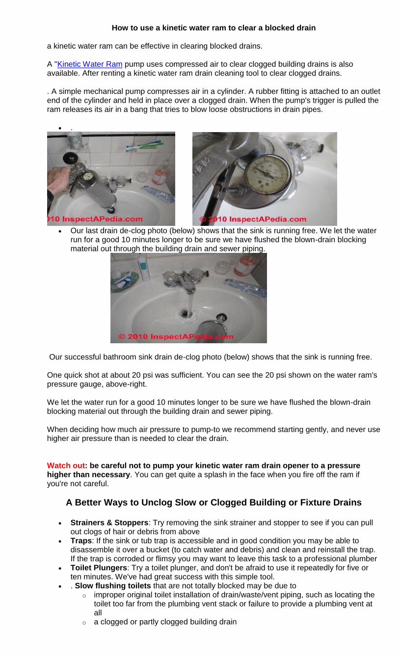
Easy Guide to Using a Plumbing Snake to Clear a Blocked Drain
v
How to use a plumbing snake to clear a blocked drain: a plumbing snake is a flexible wire or coiled wire that is gently forced down through a drain (and in some models rotated by hand or by a machine) to attempt to clear the drain. Plumbing snakes and wires are available ranging from tiny models that can clear a sink or tub trap to large two-person machine-operated rotating power snakes used by professionals to clear sewer lines. Guide to Using a Kinetic Water Ram to Open Blocked Building Drains
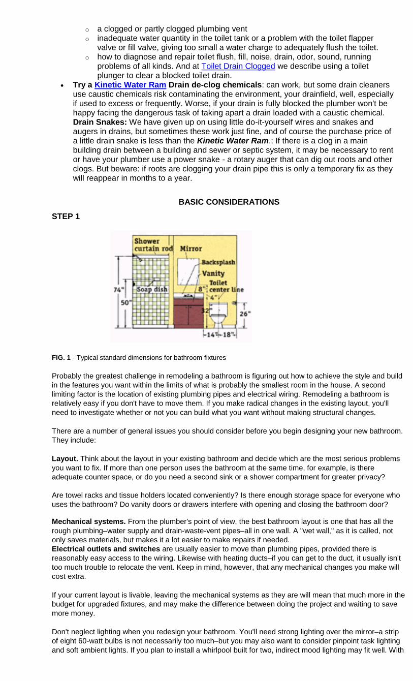
Details of using a pneumatic or kinetic water ram tool to clear blocked drains - our preferred drain de clogging method
How to use a kinetic water ram to clear a blocked drain
a kinetic water ram can be effective in clearing blocked drains.
A "Kinetic Water Ram pump uses compressed air to clear clogged building drains is also available. After renting a kinetic water ram drain cleaning tool to clear clogged drains.
. A simple mechanical pump compresses air in a cylinder. A rubber fitting is attached to an outlet end of the cylinder and held in place over a clogged drain. When the pump's trigger is pulled the ram releases its air in a bang that tries to blow loose obstructions in drain pipes.
.
Our last drain de-clog photo (below) shows that the sink is running free. We let the water
run for a good 10 minutes longer to be sure we have flushed the blown-drain blocking material out through the building drain and sewer piping.
Our successful bathroom sink drain de-clog photo (below) shows that the sink is running free.
One quick shot at about 20 psi was sufficient. You can see the 20 psi shown on the water ram's pressure gauge, above-right.
We let the water run for a good 10 minutes longer to be sure we have flushed the blown-drain blocking material out through the building drain and sewer piping.
When deciding how much air pressure to pump-to we recommend starting gently, and never use higher air pressure than is needed to clear the drain.
Watch out: be careful not to pump your kinetic water ram drain opener to a pressure higher than necessary. You can get quite a splash in the face when you fire off the ram if you're not careful.
A Better Ways to Unclog Slow or Clogged Building or Fixture Drains
Strainers & Stoppers: Try removing the sink strainer and stopper to see if you can pull out clogs of hair or debris from above
Traps: If the sink or tub trap is accessible and in good condition you may be able to disassemble it over a bucket (to catch water and debris) and clean and reinstall the trap. If the trap is corroded or flimsy you may want to leave this task to a professional plumber
Toilet Plungers: Try a toilet plunger, and don't be afraid to use it repeatedly for five or ten minutes. We've had great success with this simple tool.
. Slow flushing toilets that are not totally blocked may be due to o improper original toilet installation of drain/waste/vent piping, such as locating the
toilet too far from the plumbing vent stack or failure to provide a plumbing vent at all
o a clogged or partly clogged building drain
o a clogged or partly clogged plumbing vent o inadequate water quantity in the toilet tank or a problem with the toilet flapper
valve or fill valve, giving too small a water charge to adequately flush the toilet. o how to diagnose and repair toilet flush, fill, noise, drain, odor, sound, running
problems of all kinds. And at Toilet Drain Clogged we describe using a toilet plunger to clear a blocked toilet drain.
Try a Kinetic Water Ram Drain de-clog chemicals: can work, but some drain cleaners use caustic chemicals risk contaminating the environment, your drainfield, well, especially if used to excess or frequently. Worse, if your drain is fully blocked the plumber won't be happy facing the dangerous task of taking apart a drain loaded with a caustic chemical. Drain Snakes: We have given up on using little do-it-yourself wires and snakes and augers in drains, but sometimes these work just fine, and of course the purchase price of a little drain snake is less than the Kinetic Water Ram.: If there is a clog in a main building drain between a building and sewer or septic system, it may be necessary to rent or have your plumber use a power snake - a rotary auger that can dig out roots and other clogs. But beware: if roots are clogging your drain pipe this is only a temporary fix as they will reappear in months to a year.
BASIC CONSIDERATIONS
STEP 1
FIG. 1 - Typical standard dimensions for bathroom fixtures
Probably the greatest challenge in remodeling a bathroom is figuring out how to achieve the style and build
in the features you want within the limits of what is probably the smallest room in the house. A second
limiting factor is the location of existing plumbing pipes and electrical wiring. Remodeling a bathroom is
relatively easy if you don't have to move them. If you make radical changes in the existing layout, you'll
need to investigate whether or not you can build what you want without making structural changes.
There are a number of general issues you should consider before you begin designing your new bathroom.
They include:
Layout. Think about the layout in your existing bathroom and decide which are the most serious problems
you want to fix. If more than one person uses the bathroom at the same time, for example, is there
adequate counter space, or do you need a second sink or a shower compartment for greater privacy?
Are towel racks and tissue holders located conveniently? Is there enough storage space for everyone who
uses the bathroom? Do vanity doors or drawers interfere with opening and closing the bathroom door?
Mechanical systems. From the plumber's point of view, the best bathroom layout is one that has all the
rough plumbing–water supply and drain-waste-vent pipes–all in one wall. A "wet wall," as it is called, not
only saves materials, but makes it a lot easier to make repairs if needed.
Electrical outlets and switches are usually easier to move than plumbing pipes, provided there is
reasonably easy access to the wiring. Likewise with heating ducts–if you can get to the duct, it usually isn't
too much trouble to relocate the vent. Keep in mind, however, that any mechanical changes you make will
cost extra.
If your current layout is livable, leaving the mechanical systems as they are will mean that much more in the
budget for upgraded fixtures, and may make the difference between doing the project and waiting to save
more money.
Don't neglect lighting when you redesign your bathroom. You'll need strong lighting over the mirror–a strip
of eight 60-watt bulbs is not necessarily too much–but you may also want to consider pinpoint task lighting
and soft ambient lights. If you plan to install a whirlpool built for two, indirect mood lighting may fit well. With
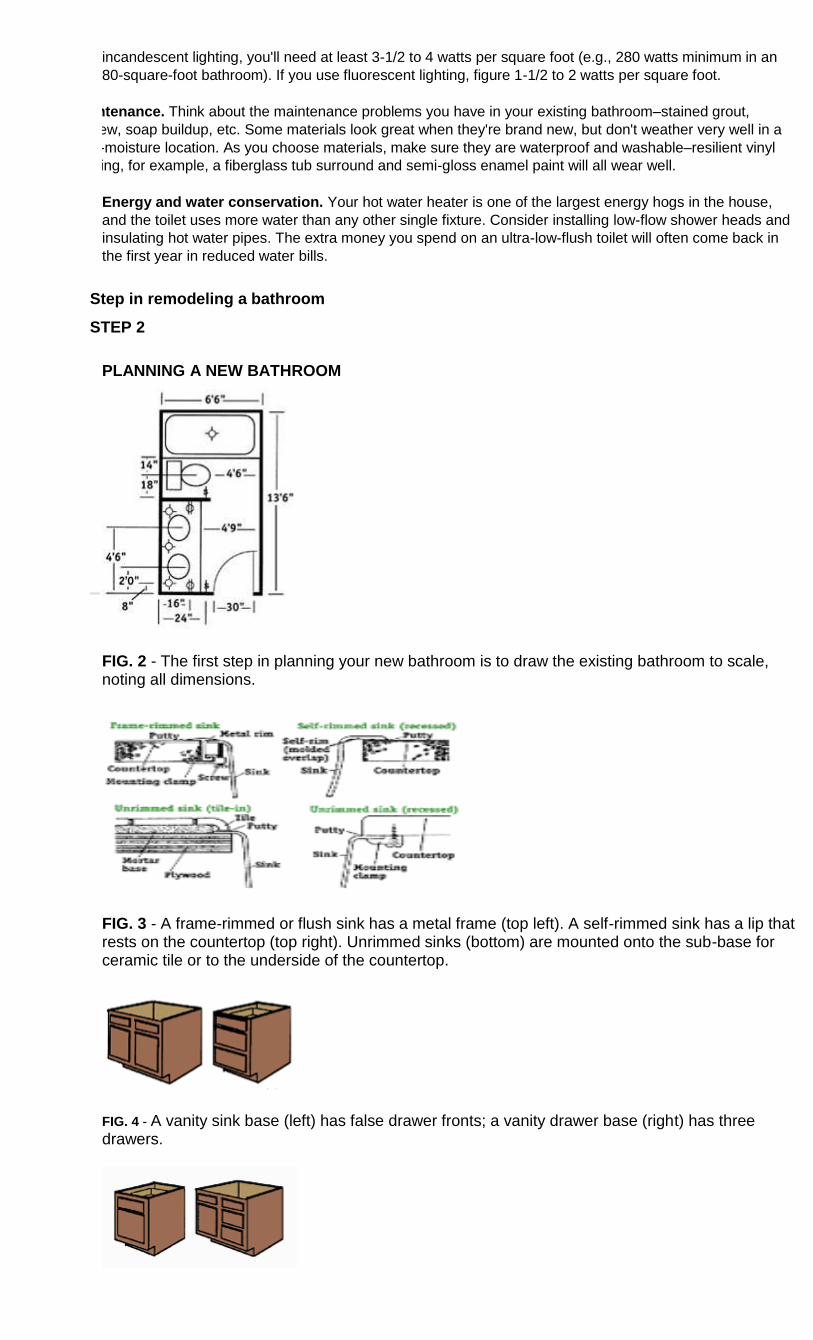
incandescent lighting, you'll need at least 3-1/2 to 4 watts per square foot (e.g., 280 watts minimum in an
80-square-foot bathroom). If you use fluorescent lighting, figure 1-1/2 to 2 watts per square foot.
Maintenance. Think about the maintenance problems you have in your existing bathroom–stained grout,
mildew, soap buildup, etc. Some materials look great when they're brand new, but don't weather very well in a
high-moisture location. As you choose materials, make sure they are waterproof and washable–resilient vinyl
flooring, for example, a fiberglass tub surround and semi-gloss enamel paint will all wear well.
Energy and water conservation. Your hot water heater is one of the largest energy hogs in the house,
and the toilet uses more water than any other single fixture. Consider installing low-flow shower heads and
insulating hot water pipes. The extra money you spend on an ultra-low-flush toilet will often come back in
the first year in reduced water bills.
Step in remodeling a bathroom
STEP 2
PLANNING A NEW BATHROOM
FIG. 2 - The first step in planning your new bathroom is to draw the existing bathroom to scale, noting all dimensions.
FIG. 3 - A frame-rimmed or flush sink has a metal frame (top left). A self-rimmed sink has a lip that rests on the countertop (top right). Unrimmed sinks (bottom) are mounted onto the sub-base for ceramic tile or to the underside of the countertop.
FIG. 4 - A vanity sink base (left) has false drawer fronts; a vanity drawer base (right) has three drawers.
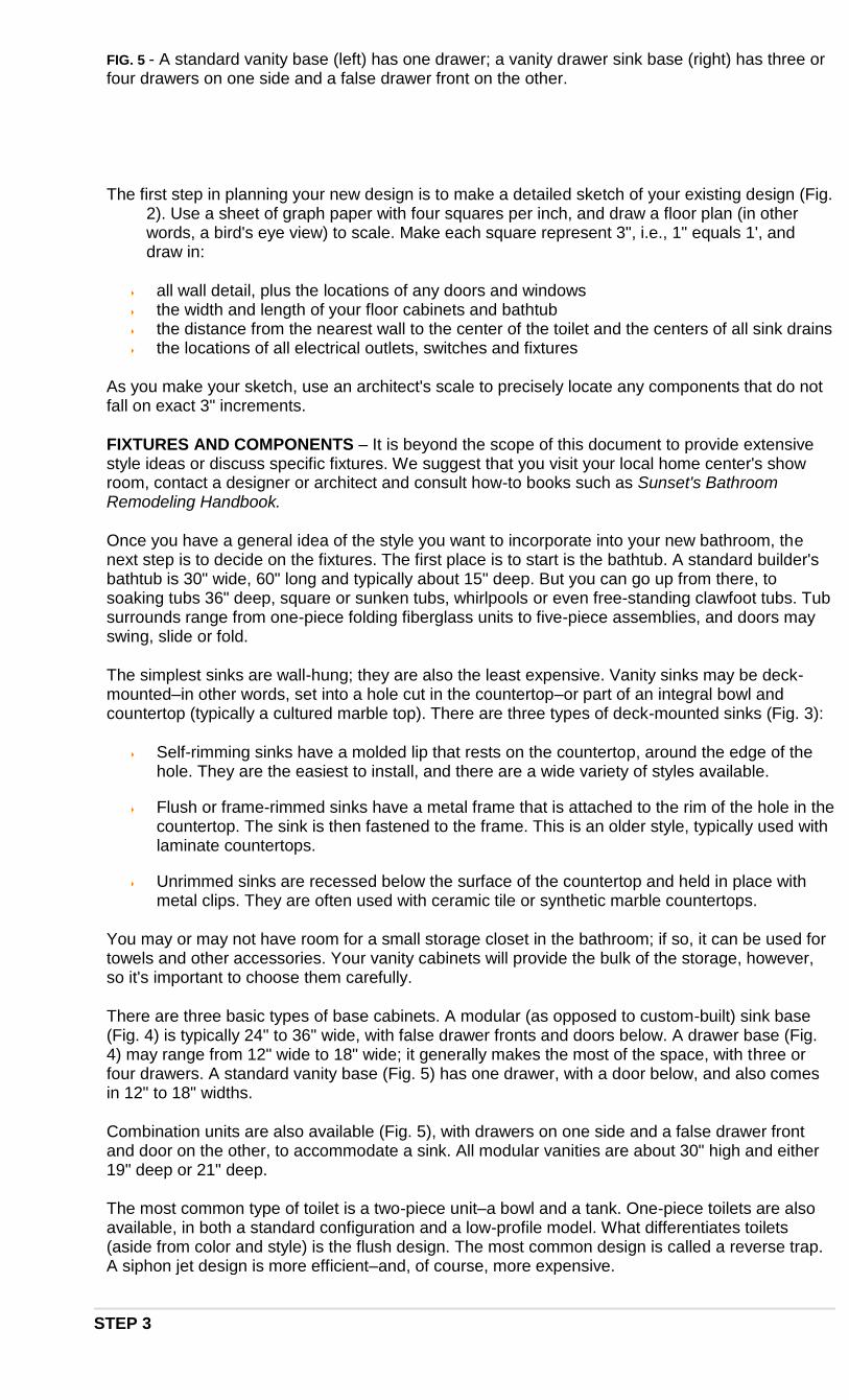
FIG. 5 - A standard vanity base (left) has one drawer; a vanity drawer sink base (right) has three or four drawers on one side and a false drawer front on the other.
The first step in planning your new design is to make a detailed sketch of your existing design (Fig. 2). Use a sheet of graph paper with four squares per inch, and draw a floor plan (in other words, a bird's eye view) to scale. Make each square represent 3", i.e., 1" equals 1', and draw in:
all wall detail, plus the locations of any doors and windows the width and length of your floor cabinets and bathtub the distance from the nearest wall to the center of the toilet and the centers of all sink drains the locations of all electrical outlets, switches and fixtures
As you make your sketch, use an architect's scale to precisely locate any components that do not fall on exact 3" increments.
FIXTURES AND COMPONENTS – It is beyond the scope of this document to provide extensive style ideas or discuss specific fixtures. We suggest that you visit your local home center's show room, contact a designer or architect and consult how-to books such as Sunset's Bathroom Remodeling Handbook.
Once you have a general idea of the style you want to incorporate into your new bathroom, the next step is to decide on the fixtures. The first place is to start is the bathtub. A standard builder's bathtub is 30" wide, 60" long and typically about 15" deep. But you can go up from there, to soaking tubs 36" deep, square or sunken tubs, whirlpools or even free-standing clawfoot tubs. Tub surrounds range from one-piece folding fiberglass units to five-piece assemblies, and doors may swing, slide or fold.
The simplest sinks are wall-hung; they are also the least expensive. Vanity sinks may be deck-mounted–in other words, set into a hole cut in the countertop–or part of an integral bowl and countertop (typically a cultured marble top). There are three types of deck-mounted sinks (Fig. 3):
Self-rimming sinks have a molded lip that rests on the countertop, around the edge of the hole. They are the easiest to install, and there are a wide variety of styles available.
Flush or frame-rimmed sinks have a metal frame that is attached to the rim of the hole in the countertop. The sink is then fastened to the frame. This is an older style, typically used with laminate countertops.
Unrimmed sinks are recessed below the surface of the countertop and held in place with metal clips. They are often used with ceramic tile or synthetic marble countertops.
You may or may not have room for a small storage closet in the bathroom; if so, it can be used for towels and other accessories. Your vanity cabinets will provide the bulk of the storage, however, so it's important to choose them carefully.
There are three basic types of base cabinets. A modular (as opposed to custom-built) sink base (Fig. 4) is typically 24" to 36" wide, with false drawer fronts and doors below. A drawer base (Fig. 4) may range from 12" wide to 18" wide; it generally makes the most of the space, with three or four drawers. A standard vanity base (Fig. 5) has one drawer, with a door below, and also comes in 12" to 18" widths.
Combination units are also available (Fig. 5), with drawers on one side and a false drawer front and door on the other, to accommodate a sink. All modular vanities are about 30" high and either 19" deep or 21" deep.
The most common type of toilet is a two-piece unit–a bowl and a tank. One-piece toilets are also available, in both a standard configuration and a low-profile model. What differentiates toilets (aside from color and style) is the flush design. The most common design is called a reverse trap. A siphon jet design is more efficient–and, of course, more expensive.
STEP 3
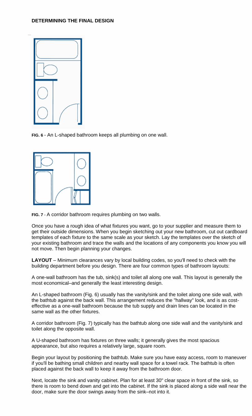
DETERMINING THE FINAL DESIGN
FIG. 6 - An L-shaped bathroom keeps all plumbing on one wall.
FIG. 7 - A corridor bathroom requires plumbing on two walls.
Once you have a rough idea of what fixtures you want, go to your supplier and measure them to get their outside dimensions. When you begin sketching out your new bathroom, cut out cardboard templates of each fixture to the same scale as your sketch. Lay the templates over the sketch of your existing bathroom and trace the walls and the locations of any components you know you will not move. Then begin planning your changes.
LAYOUT – Minimum clearances vary by local building codes, so you'll need to check with the building department before you design. There are four common types of bathroom layouts:
A one-wall bathroom has the tub, sink(s) and toilet all along one wall. This layout is generally the most economical–and generally the least interesting design.
An L-shaped bathroom (Fig. 6) usually has the vanity/sink and the toilet along one side wall, with the bathtub against the back wall. This arrangement reduces the "hallway" look, and is as cost-effective as a one-wall bathroom because the tub supply and drain lines can be located in the same wall as the other fixtures.
A corridor bathroom (Fig. 7) typically has the bathtub along one side wall and the vanity/sink and toilet along the opposite wall.
A U-shaped bathroom has fixtures on three walls; it generally gives the most spacious appearance, but also requires a relatively large, square room.
Begin your layout by positioning the bathtub. Make sure you have easy access, room to maneuver if you'll be bathing small children and nearby wall space for a towel rack. The bathtub is often placed against the back wall to keep it away from the bathroom door.
Next, locate the sink and vanity cabinet. Plan for at least 30" clear space in front of the sink, so there is room to bend down and get into the cabinet. If the sink is placed along a side wall near the door, make sure the door swings away from the sink–not into it.
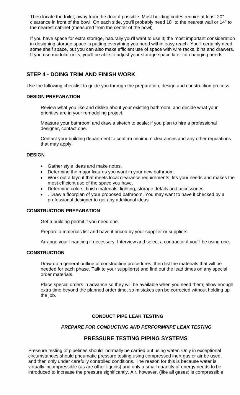
Then locate the toilet, away from the door if possible. Most building codes require at least 20" clearance in front of the bowl. On each side, you'll probably need 18" to the nearest wall or 14" to the nearest cabinet (measured from the center of the bowl).
If you have space for extra storage, naturally you'll want to use it; the most important consideration in designing storage space is putting everything you need within easy reach. You'll certainly need some shelf space, but you can also make efficient use of space with wire racks, bins and drawers. If you use modular units, you'll be able to adjust your storage space later for changing needs.
STEP 4 - DOING TRIM AND FINISH WORK
Use the following checklist to guide you through the preparation, design and construction process.
DESIGN PREPARATION
Review what you like and dislike about your existing bathroom, and decide what your priorities are in your remodeling project.
Measure your bathroom and draw a sketch to scale; if you plan to hire a professional designer, contact one.
Contact your building department to confirm minimum clearances and any other regulations that may apply.
DESIGN
Gather style ideas and make notes.
Determine the major fixtures you want in your new bathroom.
Work out a layout that meets local clearance requirements, fits your needs and makes the most efficient use of the space you have.
Determine colors, finish materials, lighting, storage details and accessories.
. Draw a floorplan of your proposed bathroom. You may want to have it checked by a professional designer to get any additional ideas
CONSTRUCTION PREPARATION
Get a building permit if you need one.
Prepare a materials list and have it priced by your supplier or suppliers.
Arrange your financing if necessary. Interview and select a contractor if you'll be using one.
CONSTRUCTION
Draw up a general outline of construction procedures, then list the materials that will be needed for each phase. Talk to your supplier(s) and find out the lead times on any special order materials.
Place special orders in advance so they will be available when you need them; allow enough extra time beyond the planned order time, so mistakes can be corrected without holding up the job.
CONDUCT PIPE LEAK TESTING
PREPARE FOR CONDUCTING AND PERFORMPIPE LEAK TESTING
PRESSURE TESTING PIPING SYSTEMS
Pressure testing of pipelines should normally be carried out using water. Only in exceptional circumstances should pneumatic pressure testing using compressed inert gas or air be used, and then only under carefully controlled conditions. The reason for this is because water is virtually incompressible (as are other liquids) and only a small quantity of energy needs to be introduced to increase the pressure significantly. Air, however, (like all gases) is compressible
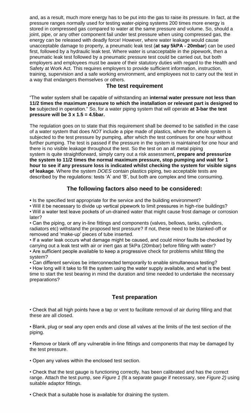
and, as a result, much more energy has to be put into the gas to raise its pressure. In fact, at the pressure ranges normally used for testing water-piping systems 200 times more energy is stored in compressed gas compared to water at the same pressure and volume. So, should a joint, pipe, or any other component fail under test pressure when using compressed gas, the energy can be released with deadly force! However, where water leakage would cause unacceptable damage to property, a pneumatic leak test (at say 5kPA - 20mbar) can be used first, followed by a hydraulic leak test. Where water is unacceptable in the pipework, then a pneumatic leak test followed by a pneumatic pressure test could be carried out, but both employers and employees must be aware of their statutory duties with regard to the Health and Safety at Work Act. This requires employers to provide sufficient information, instruction, training, supervision and a safe working environment, and employees not to carry out the test in a way that endangers themselves or others.
The test requirement ―The water system shall be capable of withstanding an internal water pressure not less than 11/2 times the maximum pressure to which the installation or relevant part is designed to be subjected in operation.― So, for a water piping system that will operate at 3-bar the test pressure will be 3 x 1.5 = 4.5bar. The regulation goes on to state that this requirement shall be deemed to be satisfied in the case of a water system that does NOT include a pipe made of plastics, where the whole system is subjected to the test pressure by pumping, after which the test continues for one hour without further pumping. The test is passed if the pressure in the system is maintained for one hour and there is no visible leakage throughout the test. So the test on an all metal piping system is quite straightforward, simply carry out a risk assessment, prepare and pressurize the system to 11/2 times the normal maximum pressure, stop pumping and wait for 1 hour to see if any pressure loss is indicated whilst checking the system for visible signs of leakage. Where the system DOES contain plastics piping, two acceptable tests are described by the regulations: tests ‗A‘ and ‗B‘, but both are complex and time consuming.
The following factors also need to be considered:
• Is the specified test appropriate for the service and the building environment? • Will it be necessary to divide up vertical pipework to limit pressures in high-rise buildings? • Will a water test leave pockets of un-drained water that might cause frost damage or corrosion later? • Can the piping, or any in-line fittings and components (valves, bellows, tanks, cylinders, radiators etc) withstand the proposed test pressure? If not, these need to be blanked-off or removed and ‗make-up‘ pieces of tube inserted. • If a water leak occurs what damage might be caused, and could minor faults be checked by carrying out a leak test with air or inert gas at 5kPa (20mbar) before filling with water? • Are sufficient people available to keep a progressive check for problems whilst filling the system? • Can different services be interconnected temporarily to enable simultaneous testing? • How long will it take to fill the system using the water supply available, and what is the best time to start the test bearing in mind the duration and time needed to undertake the necessary preparations?
Test preparation
• Check that all high points have a tap or vent to facilitate removal of air during filling and that these are all closed. • Blank, plug or seal any open ends and close all valves at the limits of the test section of the piping. • Remove or blank off any vulnerable in-line fittings and components that may be damaged by the test pressure. • Open any valves within the enclosed test section. • Check that the test gauge is functioning correctly, has been calibrated and has the correct range. Attach the test pump, see Figure 1 (fit a separate gauge if necessary, see Figure 2) using suitable adaptor fittings. • Check that a suitable hose is available for draining the system.
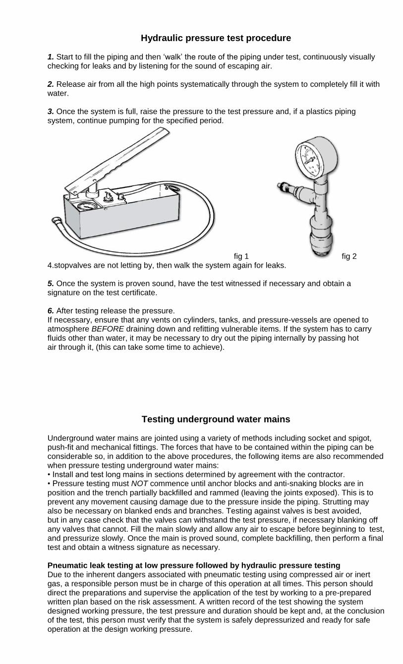
Hydraulic pressure test procedure
1. Start to fill the piping and then ‗walk‘ the route of the piping under test, continuously visually checking for leaks and by listening for the sound of escaping air. 2. Release air from all the high points systematically through the system to completely fill it with water. 3. Once the system is full, raise the pressure to the test pressure and, if a plastics piping system, continue pumping for the specified period.
fig 1 fig 2 4.stopvalves are not letting by, then walk the system again for leaks. 5. Once the system is proven sound, have the test witnessed if necessary and obtain a signature on the test certificate. 6. After testing release the pressure. If necessary, ensure that any vents on cylinders, tanks, and pressure-vessels are opened to atmosphere BEFORE draining down and refitting vulnerable items. If the system has to carry fluids other than water, it may be necessary to dry out the piping internally by passing hot air through it, (this can take some time to achieve).
Testing underground water mains
Underground water mains are jointed using a variety of methods including socket and spigot, push-fit and mechanical fittings. The forces that have to be contained within the piping can be considerable so, in addition to the above procedures, the following items are also recommended when pressure testing underground water mains: • Install and test long mains in sections determined by agreement with the contractor. • Pressure testing must NOT commence until anchor blocks and anti-snaking blocks are in position and the trench partially backfilled and rammed (leaving the joints exposed). This is to prevent any movement causing damage due to the pressure inside the piping. Strutting may also be necessary on blanked ends and branches. Testing against valves is best avoided, but in any case check that the valves can withstand the test pressure, if necessary blanking off any valves that cannot. Fill the main slowly and allow any air to escape before beginning to test, and pressurize slowly. Once the main is proved sound, complete backfilling, then perform a final test and obtain a witness signature as necessary. Pneumatic leak testing at low pressure followed by hydraulic pressure testing Due to the inherent dangers associated with pneumatic testing using compressed air or inert gas, a responsible person must be in charge of this operation at all times. This person should direct the preparations and supervise the application of the test by working to a pre-prepared written plan based on the risk assessment. A written record of the test showing the system designed working pressure, the test pressure and duration should be kept and, at the conclusion of the test, this person must verify that the system is safely depressurized and ready for safe operation at the design working pressure.
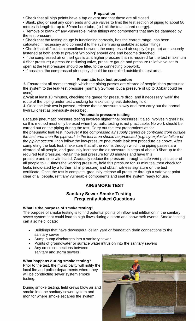
Preparation • Check that all high points have a tap or vent and that these are all closed. • Blank, plug or seal any open ends and use valves to limit the test section of piping to about 50 metres in length for up to 50mm bore tube, (to limit the total stored energy). • Remove or blank off any vulnerable in-line fittings and components that may be damaged by the test pressure. • Check that the testing gauge is functioning correctly, has the correct range, has been calibrated if necessary and connect it to the system using suitable adaptor fittings. • Check that all flexible connections between the compressed air supply (or pump) are securely fastened at both ends to prevent ‗whipping‘ should one end become detached. • If the compressed air or inert gas is at a higher pressure than is required for the test (maximum 0.5bar pressure) a pressure reducing valve, pressure gauge and pressure relief valve set to open at the test pressure should be fitted to the connecting pipework. • If possible, the compressed air supply should be controlled outside the test area.
Pneumatic leak test procedure
1. Ensure that all rooms through which the piping passes are cleared of people, then pressurise the system to the leak test pressure (normally 20mbar, but a pressure of up to 0.5bar could be used). 2.Wait at least 10 minutes, checking the gauge for pressure drop, and if necessary ‗walk‘ the route of the piping under test checking for leaks using leak detecting fluid. 3. Once the leak test is passed, release the air pressure slowly and then carry out the normal hydraulic test as previously described.
Pneumatic pressure testing Because pneumatic pressure testing involves higher final pressures, it also involves higher risk, so this method must only be used when hydraulic testing is not practicable. No work should be carried out on the piping during the test. Carry out the test preparations as for the pneumatic leak test, however if the compressed air supply cannot be controlled from outside the test area then the pipework in the test area should be protected (e.g. by explosive failure of the piping occurs! Then follow the low-pressure pneumatic leak test procedure as above. After completing the leak test, make sure that all the rooms through which the piping passes are cleared of all people, and gradually increase the air pressure in steps of about 0.5bar up to the required test pressure. Retain the test pressure for 30 minutes and have this pressure and time witnessed. Gradually reduce the pressure through a safe vent point clear of all people to 1.1 times the working pressure, hold this pressure for 30 minutes, then check for leaks (indic-ated by a further fall in pressure) and obtain witness signature on the test certificate. Once the test is complete, gradually release all pressure through a safe vent point clear of all people, refit any vulnerable components and seal the system ready for use.
AIR/SMOKE TEST
Sanitary Sewer Smoke Testing Frequently Asked Questions
What is the purpose of smoke testing? The purpose of smoke testing is to find potential points of inflow and infiltration in the sanitary sewer system that could lead to high flows during a storm and snow melt events. Smoke testing can also help locate:
Buildings that have downspout, cellar, yard or foundation drain connections to the sanitary sewer
Sump pump discharges into a sanitary sewer Points of groundwater or surface water intrusion into the sanitary sewers Any cross connections between
sanitary and storm sewers
What happens during smoke testing? Prior to the test, the municipality will notify the local fire and police departments where they will be conducting sewer system smoke testing.
During smoke testing, field crews blow air and smoke into the sanitary sewer system and monitor where smoke escapes the system.
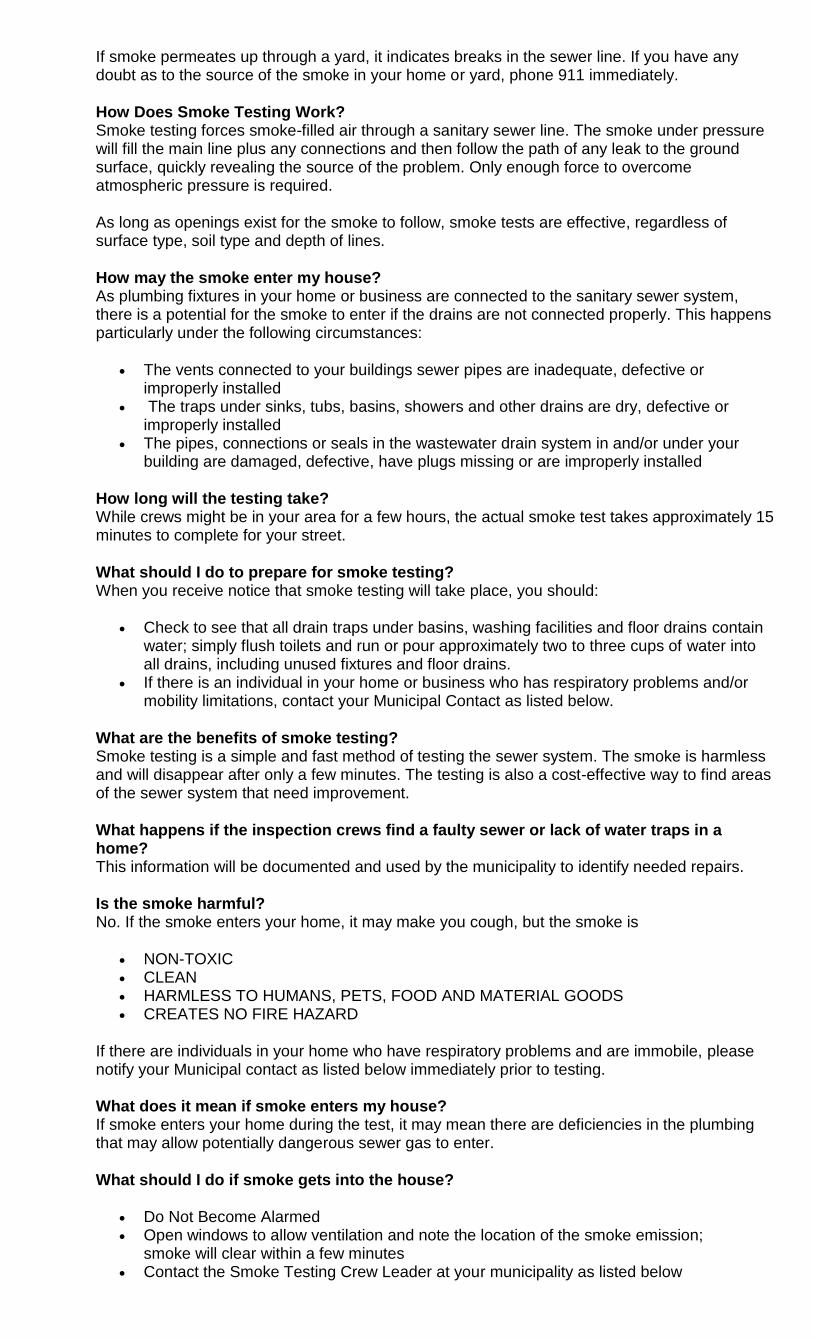
If smoke permeates up through a yard, it indicates breaks in the sewer line. If you have any doubt as to the source of the smoke in your home or yard, phone 911 immediately.
How Does Smoke Testing Work? Smoke testing forces smoke-filled air through a sanitary sewer line. The smoke under pressure will fill the main line plus any connections and then follow the path of any leak to the ground surface, quickly revealing the source of the problem. Only enough force to overcome atmospheric pressure is required.
As long as openings exist for the smoke to follow, smoke tests are effective, regardless of surface type, soil type and depth of lines.
How may the smoke enter my house? As plumbing fixtures in your home or business are connected to the sanitary sewer system, there is a potential for the smoke to enter if the drains are not connected properly. This happens particularly under the following circumstances:
The vents connected to your buildings sewer pipes are inadequate, defective or improperly installed
The traps under sinks, tubs, basins, showers and other drains are dry, defective or improperly installed
The pipes, connections or seals in the wastewater drain system in and/or under your building are damaged, defective, have plugs missing or are improperly installed
How long will the testing take? While crews might be in your area for a few hours, the actual smoke test takes approximately 15 minutes to complete for your street.
What should I do to prepare for smoke testing? When you receive notice that smoke testing will take place, you should:
Check to see that all drain traps under basins, washing facilities and floor drains contain water; simply flush toilets and run or pour approximately two to three cups of water into all drains, including unused fixtures and floor drains.
If there is an individual in your home or business who has respiratory problems and/or mobility limitations, contact your Municipal Contact as listed below.
What are the benefits of smoke testing? Smoke testing is a simple and fast method of testing the sewer system. The smoke is harmless and will disappear after only a few minutes. The testing is also a cost-effective way to find areas of the sewer system that need improvement.
What happens if the inspection crews find a faulty sewer or lack of water traps in a home? This information will be documented and used by the municipality to identify needed repairs.
Is the smoke harmful? No. If the smoke enters your home, it may make you cough, but the smoke is
NON-TOXIC CLEAN HARMLESS TO HUMANS, PETS, FOOD AND MATERIAL GOODS CREATES NO FIRE HAZARD
If there are individuals in your home who have respiratory problems and are immobile, please notify your Municipal contact as listed below immediately prior to testing. What does it mean if smoke enters my house? If smoke enters your home during the test, it may mean there are deficiencies in the plumbing that may allow potentially dangerous sewer gas to enter.
What should I do if smoke gets into the house?
Do Not Become Alarmed Open windows to allow ventilation and note the location of the smoke emission;
smoke will clear within a few minutes Contact the Smoke Testing Crew Leader at your municipality as listed below
Can the smoke testing activate the smoke alarms? Yes, smoke alarms may be activated during smoke testing. Make sure to open windows and/or doors for ventilation. If you have any doubts about the origin of the smoke, please call 911.
If you have any questions during smoke testing please call your Municipal contact, as listed below. Your call will be returned promptly
Smoke testing refers to physical tests made to closed systems of pipes to test for leaks. By metaphorical extension, the term is also used for the first test made after assembly or repairs to a system, to provide some assurance that the system under test will not catastrophically fail. After a smoke test proves that "the pipes will not leak, the keys seal properly, the circuit will not burn, or the software will not crash outright, the system is ready for more stressful testing.
Water test
Close all openings down to the lower end of the house drain and fill the pipes through the highest opening (this is usually above the roof) until the entire system is filled with water. If an examination of the waste and vent piping reveals no leaks, the system will pass inspection and the fixtures may be safely installed. One objection to the water test, however, is the fact that the pressure exerted by the water is not uniform throughout the system.
The pressure is great at the bottom of the system but relatively insignificant at the top. It is also dangerous to make the water test in freezing weather since there is a real possibility that the oakum in leaded joints will become saturated and freeze. As a result the joints may be forced out of their hubs.
Air test
Air tests are applied by closing openings and pumping air into the system until a uniform pressure of five pounds registers on a gauge. The system is kept at the same pressure for time and then tested again. Any drop in the pressure indicates a leak in the system. The air test has two principal advantages.
It can be made in freezing weather, and it subjects the entire system to a uniform pressure. On the other hand, it does not indicate location of the leak. Consequently, unless the leak is a big one, it may be difficult to find. A soapy lather applied to all joints with a brush will reveal leaks by forming bubbles wherever air is escaping.
Peppermint test
The final test, with fixtures in place, can be made with either smoke or peppermint. To make the peppermint test, seal all traps with water and all openings with caps or plugs. All windows and doors should be closed tightly in order to aid in the detection of leaks. The system is partly filled through its highest point with a solution of hot water and oil of peppermint. The tester should avoid getting oil of peppermint on his hands or clothes.
To detect the leaks, he will have to be entirely free of its odor. After solution is added, the system is capped and allowed to stand for a short time. Then the tester goes over every joint, fixture connection, and trap. Wherever he detects the odor of peppermint, there is a leak. Note that the system needs to be only partially filled with the oil and hot water mixture as it vaporizes and so reaches all points.
Smoke test
The smoke test requires the use of a smoke machine. All lower openings in the system are sealed, but the roof openings are left uncapped. Smoke is then pumped into the system until a considerable volume of it is seen issuing from the roof openings. Then they are capped. The machine continues to force smoke into the piping until a pressure equivalent to a rise of one inch in a water column gauge is reached. At this point, check all connections for signs of smoke. The principal objection to the smoke test is the possible damage it might do to interiors in the case of a line break.
Make either the peppermint or the smoke test on old piping. The peppermint test is preferred because it can be detected in places, such as underground piping, where smoke cannot. As these tests are usually made in the presence of a local building or public health inspector, you should pre-test all connections before calling him in. You should also remember that excessive

pressure in either the smoke or the air test will blow out your trap seals, defeating the entire purpose of the test. To avoid this, take care to use only recommended pressures.
GRAVITY TEST
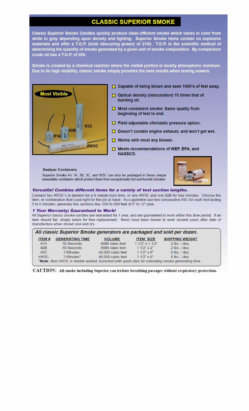
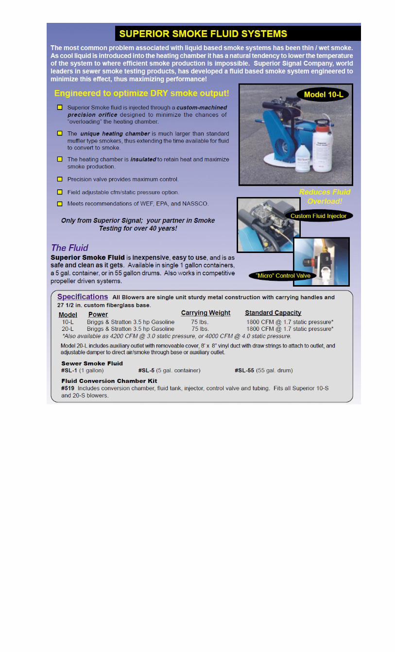
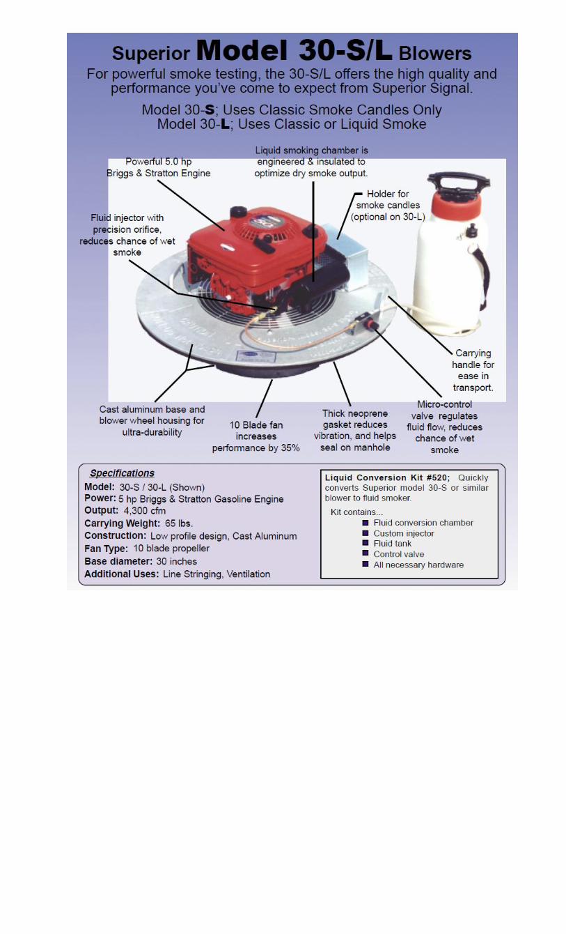
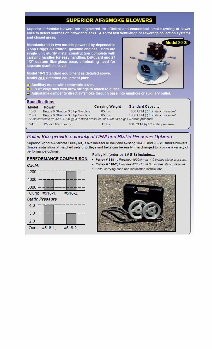
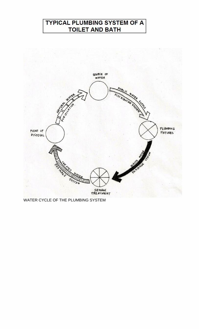
WATER CYCLE OF THE PLUMBING SYSTEM

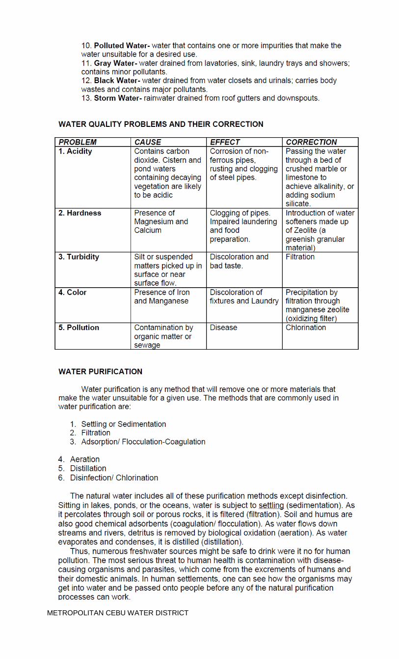
METROPOLITAN CEBU WATER DISTRICT
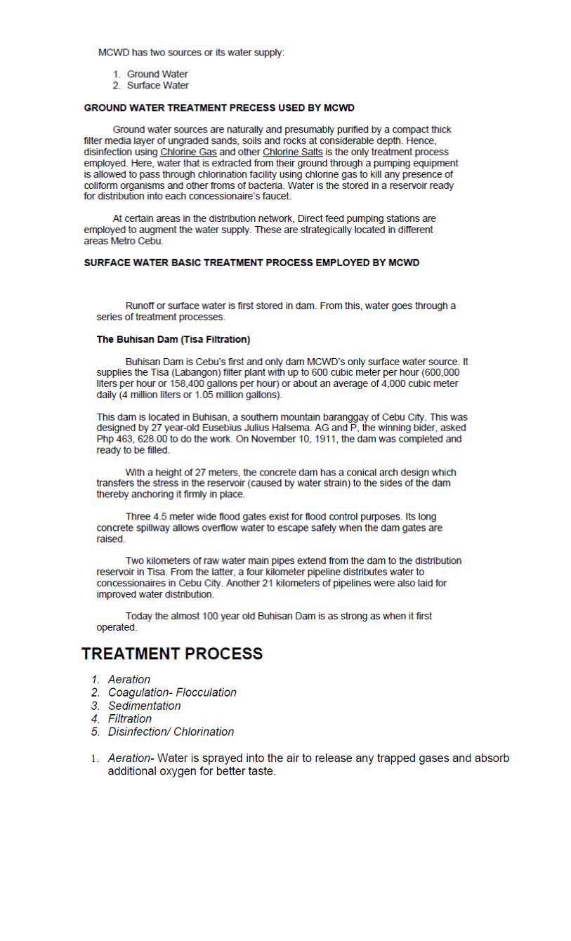
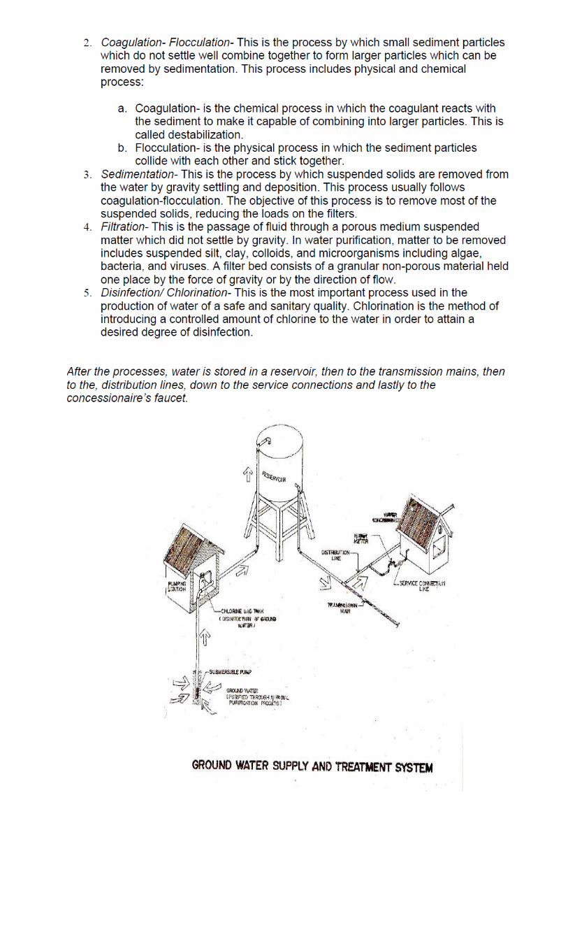
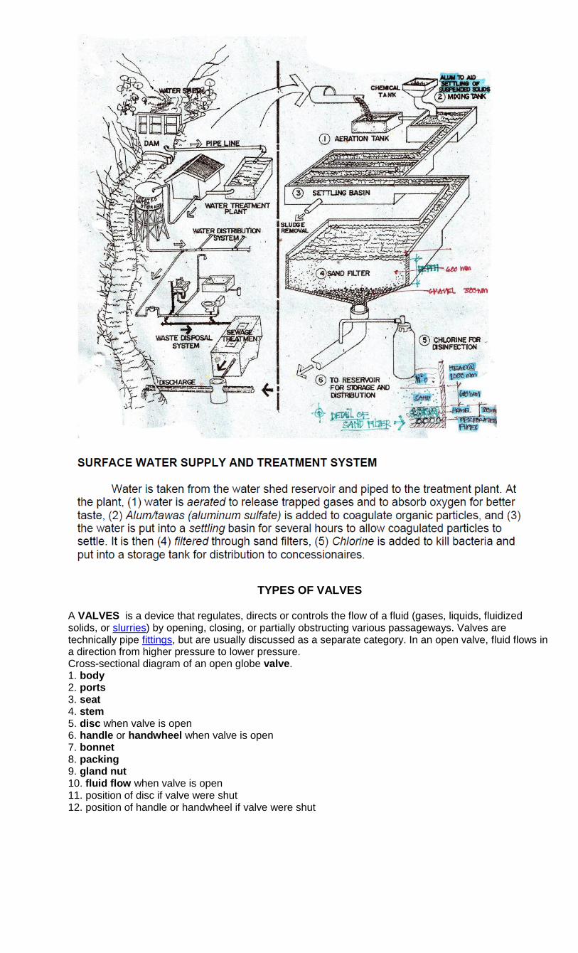
TYPES OF VALVES
A VALVES is a device that regulates, directs or controls the flow of a fluid (gases, liquids, fluidized solids, or slurries) by opening, closing, or partially obstructing various passageways. Valves are technically pipe fittings, but are usually discussed as a separate category. In an open valve, fluid flows in a direction from higher pressure to lower pressure. Cross-sectional diagram of an open globe valve. 1. body 2. ports 3. seat 4. stem 5. disc when valve is open 6. handle or handwheel when valve is open 7. bonnet 8. packing 9. gland nut 10. fluid flow when valve is open 11. position of disc if valve were shut 12. position of handle or handwheel if valve were shut
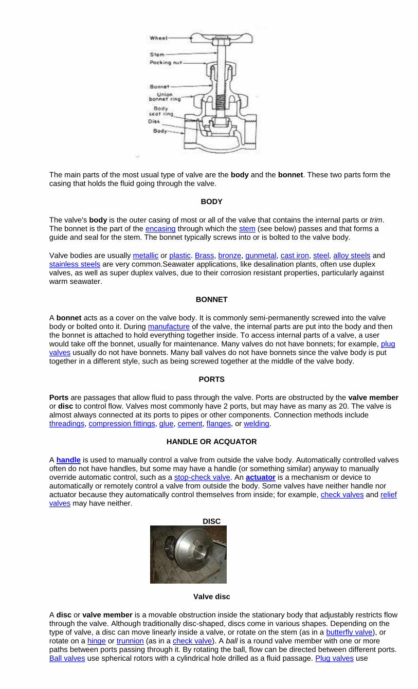
The main parts of the most usual type of valve are the body and the bonnet. These two parts form the casing that holds the fluid going through the valve.
BODY
The valve's body is the outer casing of most or all of the valve that contains the internal parts or trim. The bonnet is the part of the encasing through which the stem (see below) passes and that forms a guide and seal for the stem. The bonnet typically screws into or is bolted to the valve body.
Valve bodies are usually metallic or plastic. Brass, bronze, gunmetal, cast iron, steel, alloy steels and stainless steels are very common.Seawater applications, like desalination plants, often use duplex valves, as well as super duplex valves, due to their corrosion resistant properties, particularly against warm seawater.
BONNET
A bonnet acts as a cover on the valve body. It is commonly semi-permanently screwed into the valve body or bolted onto it. During manufacture of the valve, the internal parts are put into the body and then the bonnet is attached to hold everything together inside. To access internal parts of a valve, a user would take off the bonnet, usually for maintenance. Many valves do not have bonnets; for example, plug valves usually do not have bonnets. Many ball valves do not have bonnets since the valve body is put together in a different style, such as being screwed together at the middle of the valve body.
PORTS
Ports are passages that allow fluid to pass through the valve. Ports are obstructed by the valve member or disc to control flow. Valves most commonly have 2 ports, but may have as many as 20. The valve is almost always connected at its ports to pipes or other components. Connection methods include threadings, compression fittings, glue, cement, flanges, or welding.
HANDLE OR ACQUATOR
A handle is used to manually control a valve from outside the valve body. Automatically controlled valves often do not have handles, but some may have a handle (or something similar) anyway to manually override automatic control, such as a stop-check valve. An actuator is a mechanism or device to automatically or remotely control a valve from outside the body. Some valves have neither handle nor actuator because they automatically control themselves from inside; for example, check valves and relief valves may have neither.
DISC
Valve disc
A disc or valve member is a movable obstruction inside the stationary body that adjustably restricts flow through the valve. Although traditionally disc-shaped, discs come in various shapes. Depending on the type of valve, a disc can move linearly inside a valve, or rotate on the stem (as in a butterfly valve), or rotate on a hinge or trunnion (as in a check valve). A ball is a round valve member with one or more paths between ports passing through it. By rotating the ball, flow can be directed between different ports. Ball valves use spherical rotors with a cylindrical hole drilled as a fluid passage. Plug valves use
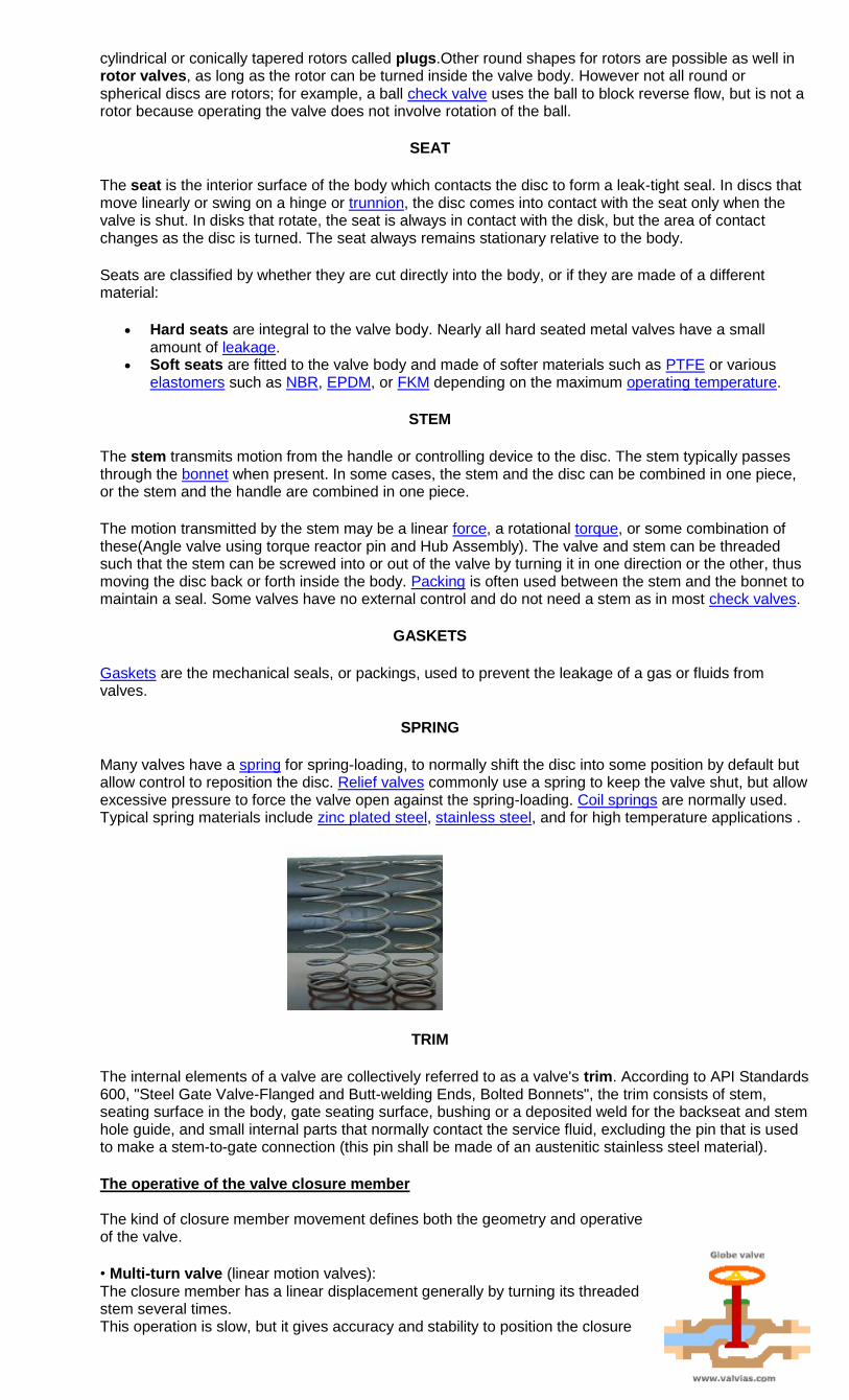
cylindrical or conically tapered rotors called plugs.Other round shapes for rotors are possible as well in rotor valves, as long as the rotor can be turned inside the valve body. However not all round or spherical discs are rotors; for example, a ball check valve uses the ball to block reverse flow, but is not a rotor because operating the valve does not involve rotation of the ball.
SEAT
The seat is the interior surface of the body which contacts the disc to form a leak-tight seal. In discs that move linearly or swing on a hinge or trunnion, the disc comes into contact with the seat only when the valve is shut. In disks that rotate, the seat is always in contact with the disk, but the area of contact changes as the disc is turned. The seat always remains stationary relative to the body.
Seats are classified by whether they are cut directly into the body, or if they are made of a different material:
Hard seats are integral to the valve body. Nearly all hard seated metal valves have a small amount of leakage.
Soft seats are fitted to the valve body and made of softer materials such as PTFE or various elastomers such as NBR, EPDM, or FKM depending on the maximum operating temperature.
STEM
The stem transmits motion from the handle or controlling device to the disc. The stem typically passes through the bonnet when present. In some cases, the stem and the disc can be combined in one piece, or the stem and the handle are combined in one piece.
The motion transmitted by the stem may be a linear force, a rotational torque, or some combination of these(Angle valve using torque reactor pin and Hub Assembly). The valve and stem can be threaded such that the stem can be screwed into or out of the valve by turning it in one direction or the other, thus moving the disc back or forth inside the body. Packing is often used between the stem and the bonnet to maintain a seal. Some valves have no external control and do not need a stem as in most check valves.
GASKETS
Gaskets are the mechanical seals, or packings, used to prevent the leakage of a gas or fluids from valves.
SPRING
Many valves have a spring for spring-loading, to normally shift the disc into some position by default but allow control to reposition the disc. Relief valves commonly use a spring to keep the valve shut, but allow excessive pressure to force the valve open against the spring-loading. Coil springs are normally used. Typical spring materials include zinc plated steel, stainless steel, and for high temperature applications .
TRIM
The internal elements of a valve are collectively referred to as a valve's trim. According to API Standards 600, "Steel Gate Valve-Flanged and Butt-welding Ends, Bolted Bonnets", the trim consists of stem, seating surface in the body, gate seating surface, bushing or a deposited weld for the backseat and stem hole guide, and small internal parts that normally contact the service fluid, excluding the pin that is used to make a stem-to-gate connection (this pin shall be made of an austenitic stainless steel material).
The operative of the valve closure member The kind of closure member movement defines both the geometry and operative of the valve.
• Multi-turn valve (linear motion valves): The closure member has a linear displacement generally by turning its threaded stem several times. This operation is slow, but it gives accuracy and stability to position the closure
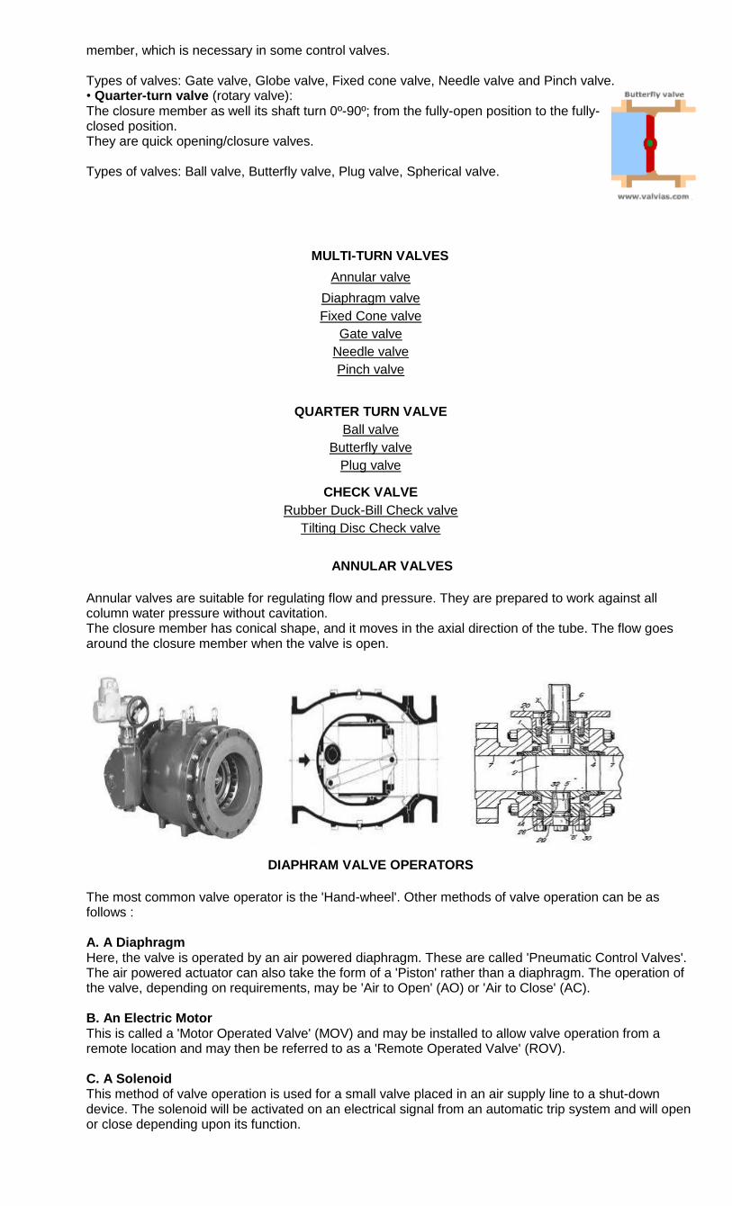
member, which is necessary in some control valves. Types of valves: Gate valve, Globe valve, Fixed cone valve, Needle valve and Pinch valve. • Quarter-turn valve (rotary valve): The closure member as well its shaft turn 0º-90º; from the fully-open position to the fully-closed position. They are quick opening/closure valves. Types of valves: Ball valve, Butterfly valve, Plug valve, Spherical valve.
MULTI-TURN VALVES
Annular valve
Diaphragm valve
Fixed Cone valve
Gate valve
Needle valve
Pinch valve
QUARTER TURN VALVE
Ball valve
Butterfly valve
Plug valve
CHECK VALVE
Rubber Duck-Bill Check valve
Tilting Disc Check valve
ANNULAR VALVES
Annular valves are suitable for regulating flow and pressure. They are prepared to work against all column water pressure without cavitation. The closure member has conical shape, and it moves in the axial direction of the tube. The flow goes around the closure member when the valve is open.
DIAPHRAM VALVE OPERATORS
The most common valve operator is the 'Hand-wheel'. Other methods of valve operation can be as follows : A. A Diaphragm Here, the valve is operated by an air powered diaphragm. These are called 'Pneumatic Control Valves'. The air powered actuator can also take the form of a 'Piston' rather than a diaphragm. The operation of the valve, depending on requirements, may be 'Air to Open' (AO) or 'Air to Close' (AC). B. An Electric Motor This is called a 'Motor Operated Valve' (MOV) and may be installed to allow valve operation from a remote location and may then be referred to as a 'Remote Operated Valve' (ROV). C. A Solenoid This method of valve operation is used for a small valve placed in an air supply line to a shut-down device. The solenoid will be activated on an electrical signal from an automatic trip system and will open or close depending upon its function.
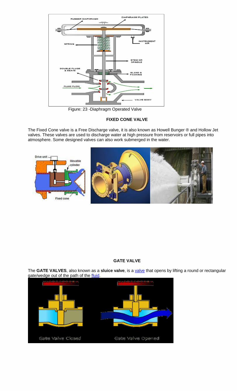
Figure: 23 -Diaphragm Operated Valve
FIXED CONE VALVE
The Fixed Cone valve is a Free Discharge valve, it is also known as Howell Bunger ® and Hollow Jet valves. These valves are used to discharge water at high pressure from reservoirs or full pipes into atmosphere. Some designed valves can also work submerged in the water.
GATE VALVE The GATE VALVES, also known as a sluice valve, is a valve that opens by lifting a round or rectangular gate/wedge out of the path of the fluid.
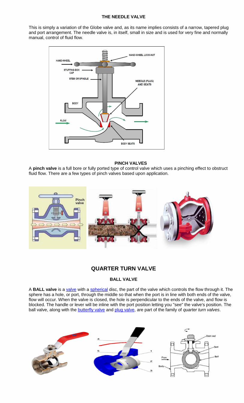
THE NEEDLE VALVE
This is simply a variation of the Globe valve and, as its name implies consists of a narrow, tapered plug and port arrangement. The needle valve is, in itself, small in size and is used for very fine and normally manual, control of fluid flow.
PINCH VALVES
A pinch valve is a full bore or fully ported type of control valve which uses a pinching effect to obstruct fluid flow. There are a few types of pinch valves based upon application.
QUARTER TURN VALVE
BALL VALVE
A BALL valve is a valve with a spherical disc, the part of the valve which controls the flow through it. The sphere has a hole, or port, through the middle so that when the port is in line with both ends of the valve, flow will occur. When the valve is closed, the hole is perpendicular to the ends of the valve, and flow is blocked. The handle or lever will be inline with the port position letting you "see" the valve's position. The ball valve, along with the butterfly valve and plug valve, are part of the family of quarter turn valves.
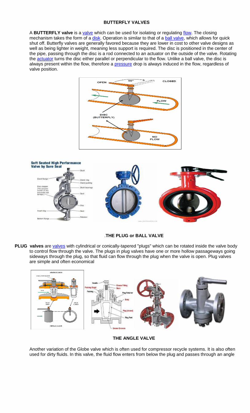
BUTTERFLY VALVES
A BUTTERFLY valve is a valve which can be used for isolating or regulating flow. The closing mechanism takes the form of a disk. Operation is similar to that of a ball valve, which allows for quick shut off. Butterfly valves are generally favored because they are lower in cost to other valve designs as well as being lighter in weight, meaning less support is required. The disc is positioned in the center of the pipe, passing through the disc is a rod connected to an actuator on the outside of the valve. Rotating the actuator turns the disc either parallel or perpendicular to the flow. Unlike a ball valve, the disc is always present within the flow, therefore a pressure drop is always induced in the flow, regardless of valve position.
.THE PLUG or BALL VALVE
PLUG valves are valves with cylindrical or conically-tapered "plugs" which can be rotated inside the valve body to control flow through the valve. The plugs in plug valves have one or more hollow passageways going sideways through the plug, so that fluid can flow through the plug when the valve is open. Plug valves are simple and often economical
THE ANGLE VALVE
Another variation of the Globe valve which is often used for compressor recycle systems. It is also often used for dirty fluids. In this valve, the fluid flow enters from below the plug and passes through an angle
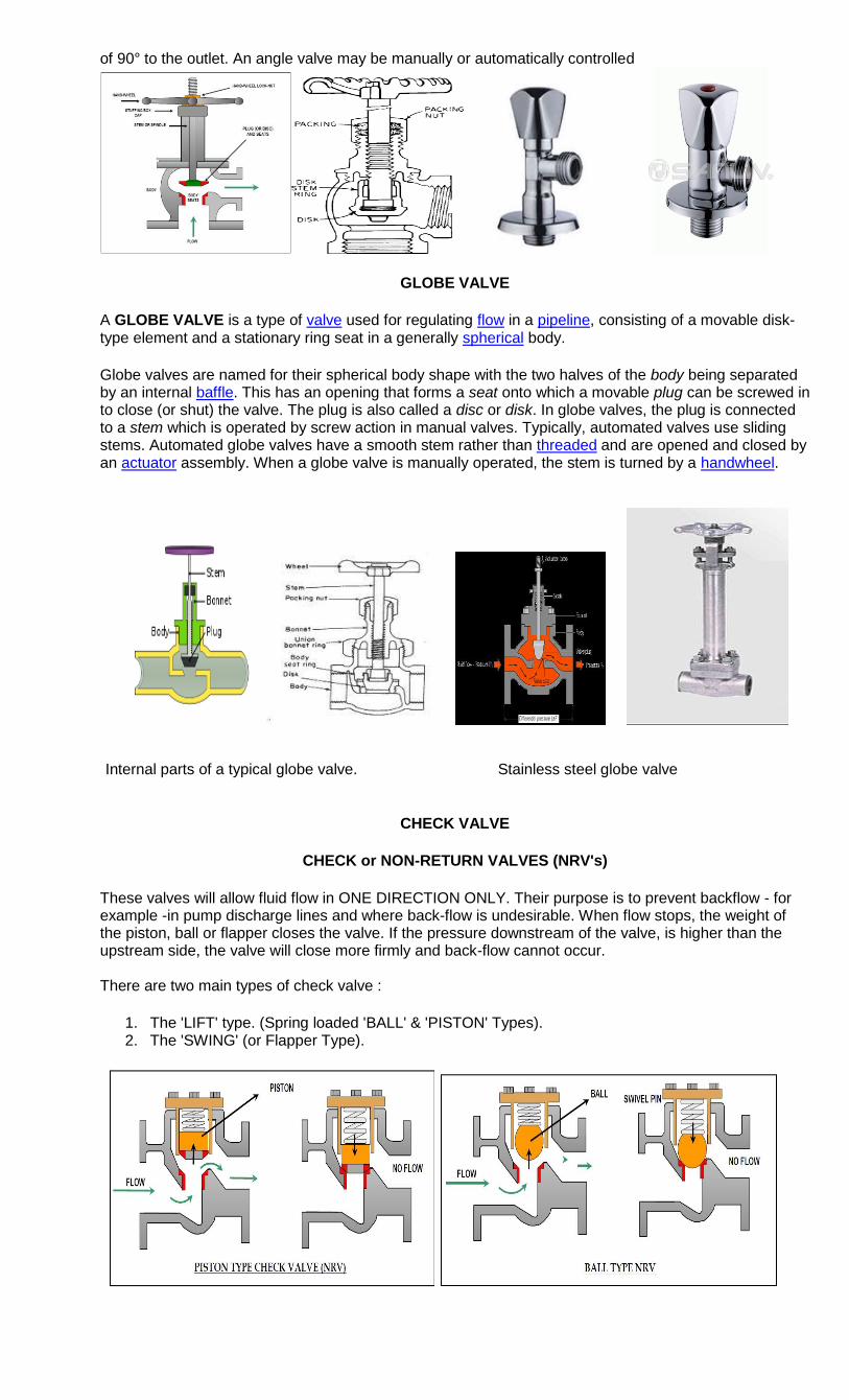
of 90° to the outlet. An angle valve may be manually or automatically controlled
GLOBE VALVE
A GLOBE VALVE is a type of valve used for regulating flow in a pipeline, consisting of a movable disk-type element and a stationary ring seat in a generally spherical body.
Globe valves are named for their spherical body shape with the two halves of the body being separated by an internal baffle. This has an opening that forms a seat onto which a movable plug can be screwed in to close (or shut) the valve. The plug is also called a disc or disk. In globe valves, the plug is connected to a stem which is operated by screw action in manual valves. Typically, automated valves use sliding stems. Automated globe valves have a smooth stem rather than threaded and are opened and closed by an actuator assembly. When a globe valve is manually operated, the stem is turned by a handwheel.
Internal parts of a typical globe valve. Stainless steel globe valve
CHECK VALVE
CHECK or NON-RETURN VALVES (NRV's)
These valves will allow fluid flow in ONE DIRECTION ONLY. Their purpose is to prevent backflow - for example -in pump discharge lines and where back-flow is undesirable. When flow stops, the weight of the piston, ball or flapper closes the valve. If the pressure downstream of the valve, is higher than the upstream side, the valve will close more firmly and back-flow cannot occur. There are two main types of check valve :
1. The 'LIFT' type. (Spring loaded 'BALL' & 'PISTON' Types). 2. The 'SWING' (or Flapper Type).
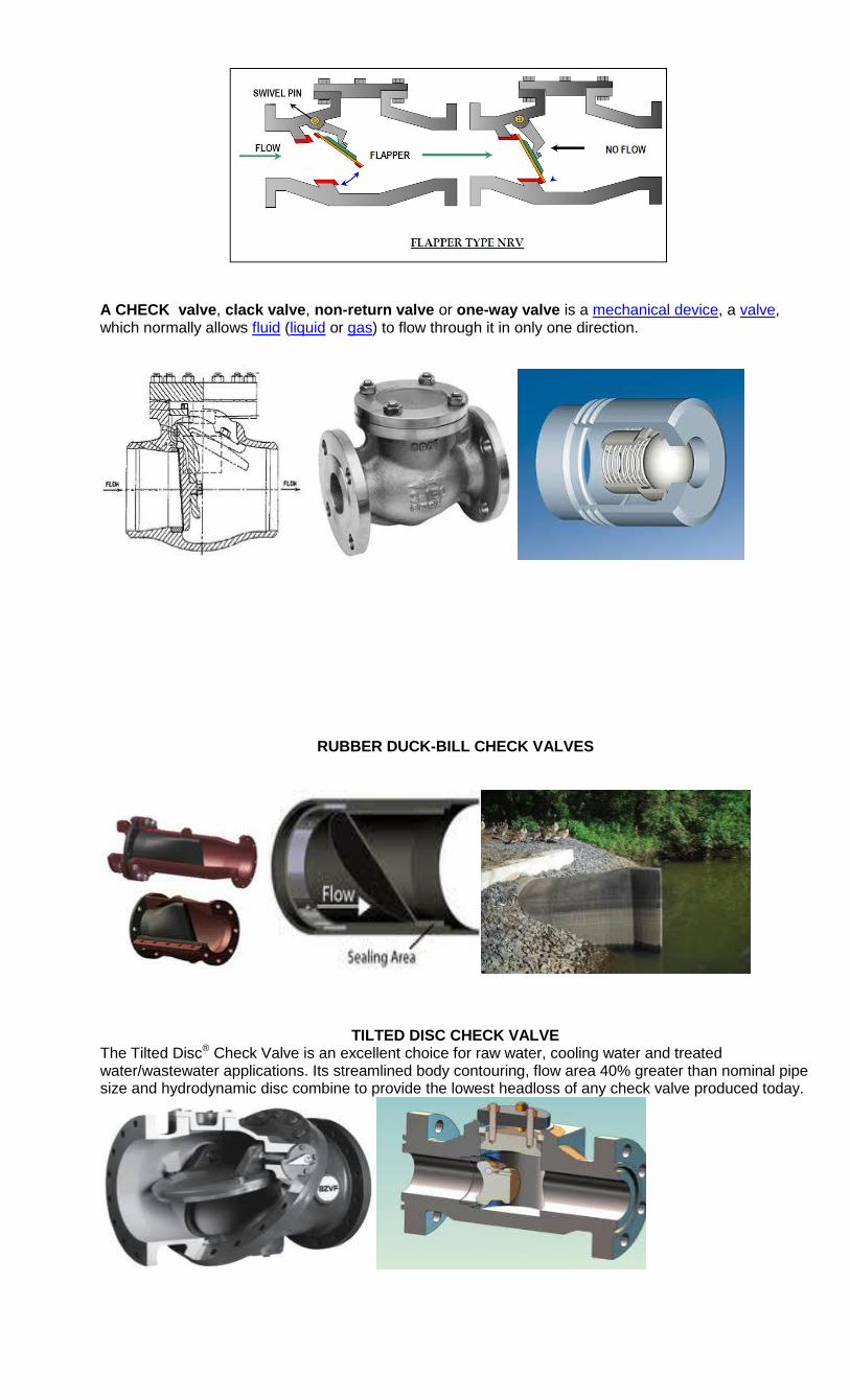
A CHECK valve, clack valve, non-return valve or one-way valve is a mechanical device, a valve, which normally allows fluid (liquid or gas) to flow through it in only one direction.
RUBBER DUCK-BILL CHECK VALVES
TILTED DISC CHECK VALVE The Tilted Disc® Check Valve is an excellent choice for raw water, cooling water and treated water/wastewater applications. Its streamlined body contouring, flow area 40% greater than nominal pipe size and hydrodynamic disc combine to provide the lowest headloss of any check valve produced today.
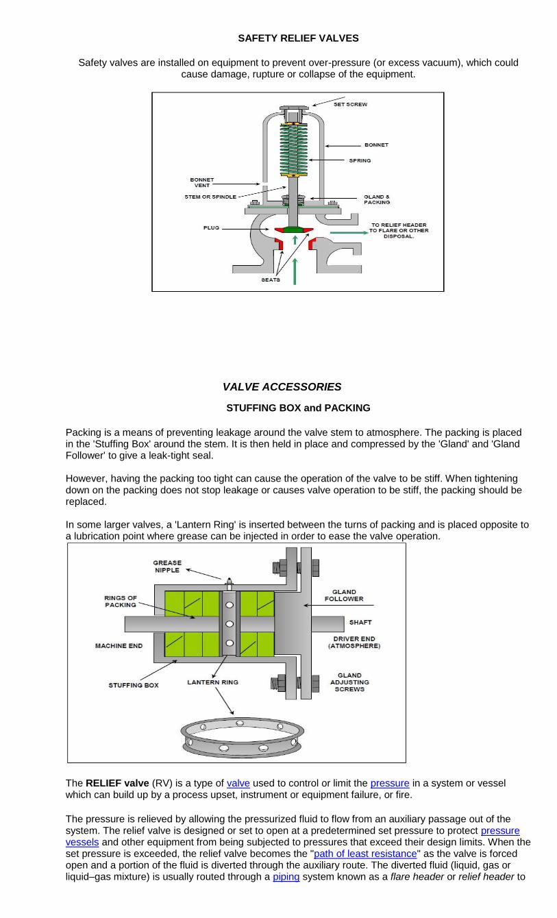
SAFETY RELIEF VALVES
Safety valves are installed on equipment to prevent over-pressure (or excess vacuum), which could cause damage, rupture or collapse of the equipment.
VALVE ACCESSORIES
STUFFING BOX and PACKING
Packing is a means of preventing leakage around the valve stem to atmosphere. The packing is placed in the 'Stuffing Box' around the stem. It is then held in place and compressed by the 'Gland' and 'Gland Follower' to give a leak-tight seal. However, having the packing too tight can cause the operation of the valve to be stiff. When tightening down on the packing does not stop leakage or causes valve operation to be stiff, the packing should be replaced. In some larger valves, a 'Lantern Ring' is inserted between the turns of packing and is placed opposite to a lubrication point where grease can be injected in order to ease the valve operation.
The RELIEF valve (RV) is a type of valve used to control or limit the pressure in a system or vessel which can build up by a process upset, instrument or equipment failure, or fire.
The pressure is relieved by allowing the pressurized fluid to flow from an auxiliary passage out of the system. The relief valve is designed or set to open at a predetermined set pressure to protect pressure vessels and other equipment from being subjected to pressures that exceed their design limits. When the set pressure is exceeded, the relief valve becomes the "path of least resistance" as the valve is forced open and a portion of the fluid is diverted through the auxiliary route. The diverted fluid (liquid, gas or liquid–gas mixture) is usually routed through a piping system known as a flare header or relief header to
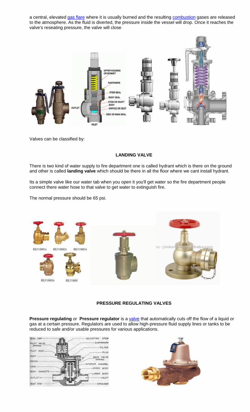
a central, elevated gas flare where it is usually burned and the resulting combustion gases are released to the atmosphere. As the fluid is diverted, the pressure inside the vessel will drop. Once it reaches the valve's reseating pressure, the valve will close
Valves can be classified by:
LANDING VALVE
There is two kind of water supply to fire department one is called hydrant which is there on the ground and other is called landing valve which should be there in all the floor where we cant install hydrant.
Its a simple valve like our water tab when you open it you'll get water so the fire department people connect there water hose to that valve to get water to extinguish fire.
The normal pressure should be 65 psi.
PRESSURE REGULATING VALVES Pressure regulating or Pressure regulator is a valve that automatically cuts off the flow of a liquid or gas at a certain pressure. Regulators are used to allow high-pressure fluid supply lines or tanks to be reduced to safe and/or usable pressures for various applications.
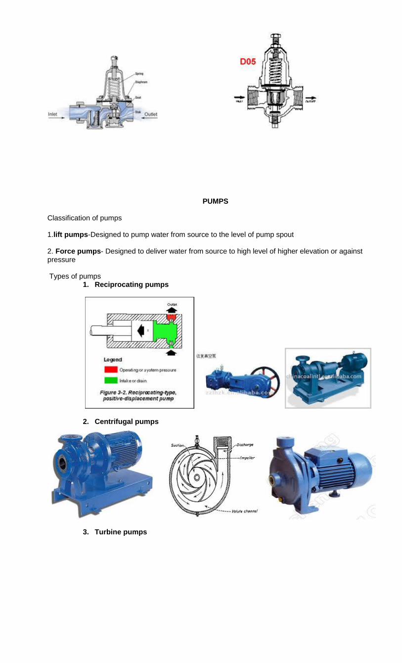
PUMPS
Classification of pumps 1.lift pumps-Designed to pump water from source to the level of pump spout 2. Force pumps- Designed to deliver water from source to high level of higher elevation or against pressure Types of pumps
1. Reciprocating pumps
2. Centrifugal pumps
3. Turbine pumps
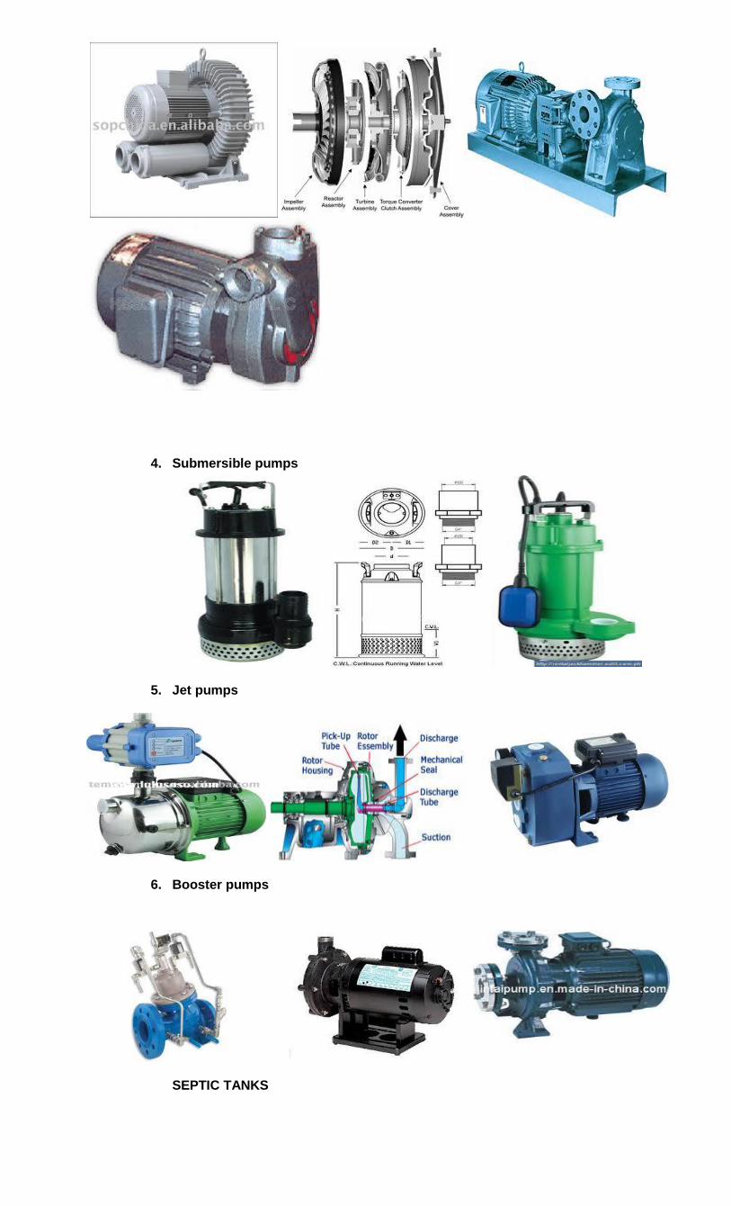
4. Submersible pumps
5. Jet pumps
6. Booster pumps
SEPTIC TANKS
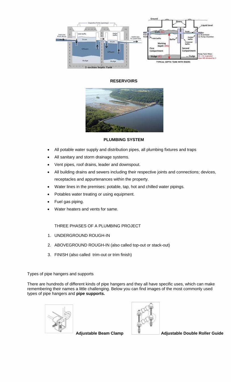
RESERVOIRS
PLUMBING SYSTEM
All potable water supply and distribution pipes, all plumbing fixtures and traps
All sanitary and storm drainage systems.
Vent pipes, roof drains, leader and downspout.
All building drains and sewers including their respective joints and connections; devices,
receptacles and appurtenances within the property.
Water lines in the premises: potable, tap, hot and chilled water pipings.
Potables water treating or using equipment.
Fuel gas piping.
Water heaters and vents for same.
THREE PHASES OF A PLUMBING PROJECT
1. UNDERGROUND ROUGH-IN
2. ABOVEGROUND ROUGH-IN (also called top-out or stack-out)
3. FINISH (also called trim-out or trim finish) Types of pipe hangers and supports
There are hundreds of different kinds of pipe hangers and they all have specific uses, which can make remembering their names a little challenging. Below you can find images of the most commonly used types of pipe hangers and pipe supports.
Adjustable Beam Clamp Adjustable Double Roller Guide
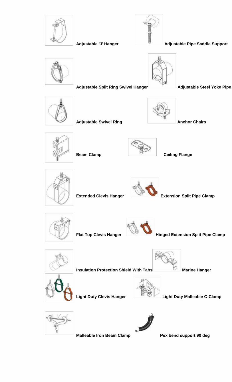
Adjustable 'J' Hanger Adjustable Pipe Saddle Support
Adjustable Split Ring Swivel Hanger Adjustable Steel Yoke Pipe
Adjustable Swivel Ring Anchor Chairs
Beam Clamp Ceiling Flange
Extended Clevis Hanger Extension Split Pipe Clamp
Flat Top Clevis Hanger Hinged Extension Split Pipe Clamp
Insulation Protection Shield With Tabs Marine Hanger
Light Duty Clevis Hanger Light Duty Malleable C-Clamp
Malleable Iron Beam Clamp Pex bend support 90 deg
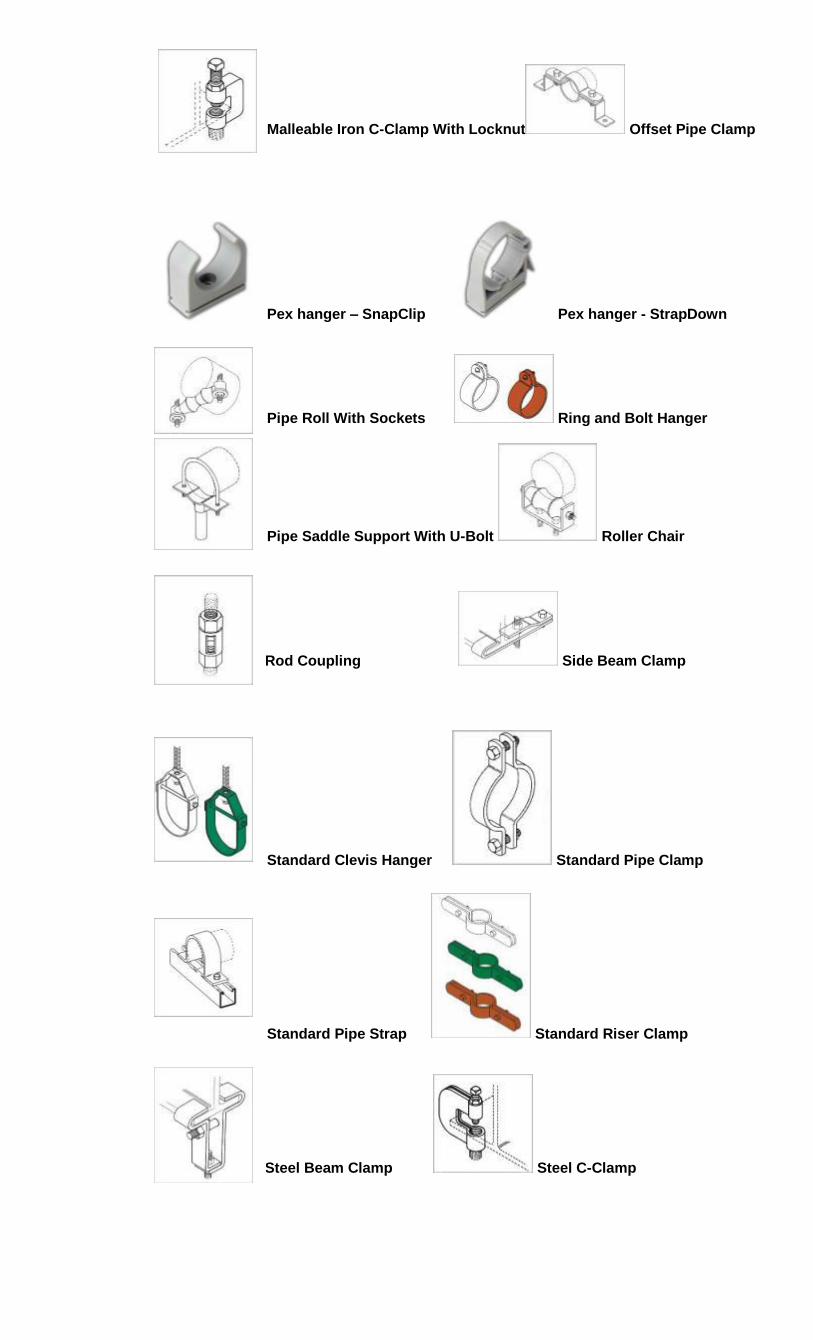
Malleable Iron C-Clamp With Locknut Offset Pipe Clamp
Pex hanger – SnapClip Pex hanger - StrapDown
Pipe Roll With Sockets Ring and Bolt Hanger
Pipe Saddle Support With U-Bolt Roller Chair
Rod Coupling Side Beam Clamp
Standard Clevis Hanger Standard Pipe Clamp
Standard Pipe Strap Standard Riser Clamp
Steel Beam Clamp Steel C-Clamp
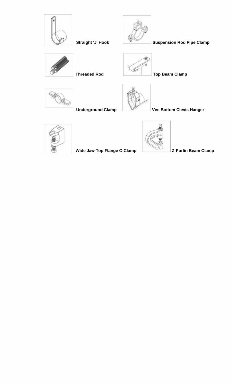
Straight 'J' Hook Suspension Rod Pipe Clamp
Threaded Rod Top Beam Clamp
Underground Clamp Vee Bottom Clevis Hanger
Wide Jaw Top Flange C-Clamp Z-Purlin Beam Clamp