Embed Size (px)
Citation preview
QM PMBus App Note 260368 V1.0.docx
QM
AC/DC Modular Power Supply Series
PMBus™ APPLICATION NOTES
QM PMBus App Note 260368 V1.0.docx
Contents
1. Overview of the PMBus™ Interface .................................................................................................... 3
2. Hardware Interface ............................................................................................................................. 3
3. Setting the PMBus™ Address .............................................................................................................. 4
4. Supported PMBus™ Commands ......................................................................................................... 5
5. Controlling the Module Outputs of the Unit ...................................................................................... 6
Modes of Operation ............................................................................................................................ 6
On/Off Configuration – Command 02h .............................................................................................. 6
Operation – Command 01h ................................................................................................................ 6
Control Line Operation ....................................................................................................................... 7
6. Reading Status from the Unit - Errors and Warnings ......................................................................... 8
Status Byte – Command 78h ............................................................................................................... 8
STATUS_FANS_1_2 Status Byte – Command 81h ............................................................................... 8
Clear Faults – Command 03h .............................................................................................................. 9
7. Reading Data from the Unit .............................................................................................................. 10
Read Temperature – Command 8Dh ................................................................................................ 10
Read Fan speed 1 – Command 90h .................................................................................................. 10
Read Fan speed 2 – Command 91h .................................................................................................. 10
Model ID – Command 9Ah ................................................................................................................ 10
Manufacture Date – Command 9Dh ................................................................................................. 10
Serial Number – Command 9Eh ........................................................................................................ 10
Runtime – Command C4h ................................................................................................................. 11
Power Cycle Count – Command C5h ................................................................................................ 11
S/W Version Number – Command C6h ............................................................................................ 11
8. Miscellaneous Commands ................................................................................................................ 12
Capability – Command 19h ............................................................................................................... 12
PMBus™ Revision – Command 98h .................................................................................................. 12
9. LINEAR11 Data Format ...................................................................................................................... 12
10. Recommended Operation ............................................................................................................... 13
11. General Notes ................................................................................................................................. 13
12. Recommended PMBus™ Interface Adapter ................................................................................... 13
13. References ...................................................................................................................................... 14
QM PMBus App Note 260368 V1.0.docx
1. Overview of the PMBus™ Interface
Standard 100kHz operation
PEC (Packet Error Checking) supported
Monitoring of status - reading and clearing of fault and warning indications
Reading manufacturing related data – manufacturer id, model name, serial number & manufacturing
date
Reading of fan speeds and inlet temperature
Reading operating time and power cycle count
On/Off control of the module outputs by PMBus™ Command, PMBus™ Control Pin, or a combination
of both
Up to 8 units may be connected to a single PMBus™ controller
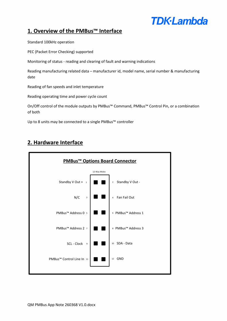
2. Hardware Interface
1 2
PMBus™ Options Board Connector
3 4
5 6
7 8
9 10
11 12
Standby V Out +
N/C
PMBus™ Address 0
SCL - Clock SDA - Data
GND
Standby V Out -
Fan Fail Out
PMBus™ Address 3
PMBus™ Address 1
PMBus™ Address 2
PMBus™ Control Line In
12-Way Molex
QM PMBus App Note 260368 V1.0.docx
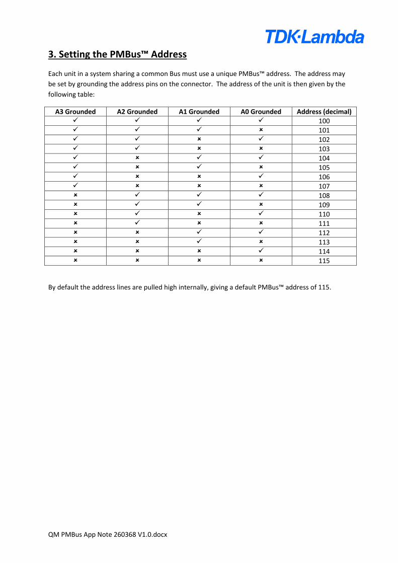
3. Setting the PMBus™ Address
Each unit in a system sharing a common Bus must use a unique PMBus™ address. The address may
be set by grounding the address pins on the connector. The address of the unit is then given by the
following table:
A3 Grounded A2 Grounded A1 Grounded A0 Grounded Address (decimal) 100 101 102 103 104 105 106 107 108 109 110 111 112 113 114 115
By default the address lines are pulled high internally, giving a default PMBus™ address of 115.
QM PMBus App Note 260368 V1.0.docx
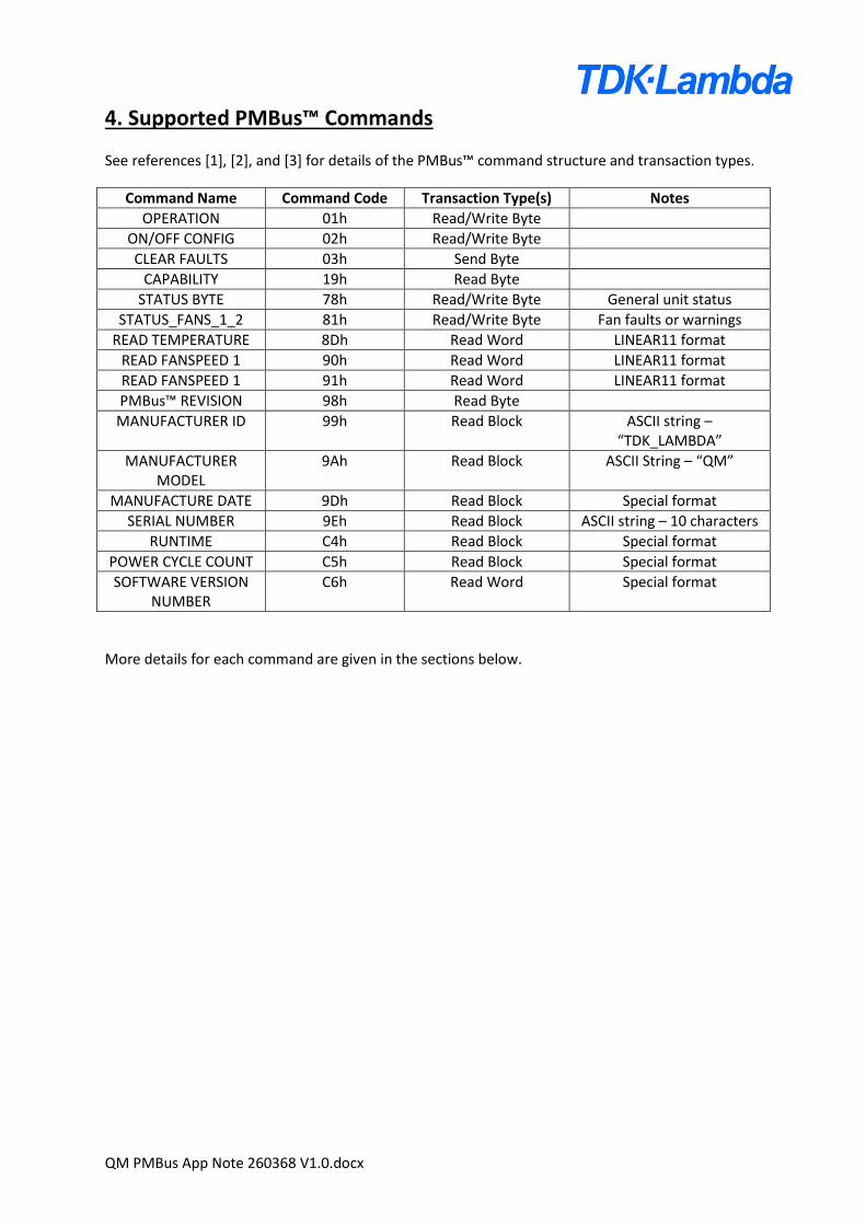
4. Supported PMBus™ Commands
See references [1], [2], and [3] for details of the PMBus™ command structure and transaction types.
Command Name Command Code Transaction Type(s) Notes
OPERATION 01h Read/Write Byte
ON/OFF CONFIG 02h Read/Write Byte
CLEAR FAULTS 03h Send Byte
CAPABILITY 19h Read Byte
STATUS BYTE 78h Read/Write Byte General unit status
STATUS_FANS_1_2 81h Read/Write Byte Fan faults or warnings
READ TEMPERATURE 8Dh Read Word LINEAR11 format
READ FANSPEED 1 90h Read Word LINEAR11 format
READ FANSPEED 1 91h Read Word LINEAR11 format
PMBus™ REVISION 98h Read Byte
MANUFACTURER ID 99h Read Block ASCII string – “TDK_LAMBDA”
MANUFACTURER MODEL
9Ah Read Block ASCII String – “QM”
MANUFACTURE DATE 9Dh Read Block Special format
SERIAL NUMBER 9Eh Read Block ASCII string – 10 characters
RUNTIME C4h Read Block Special format
POWER CYCLE COUNT C5h Read Block Special format
SOFTWARE VERSION NUMBER
C6h Read Word Special format
More details for each command are given in the sections below.
QM PMBus App Note 260368 V1.0.docx
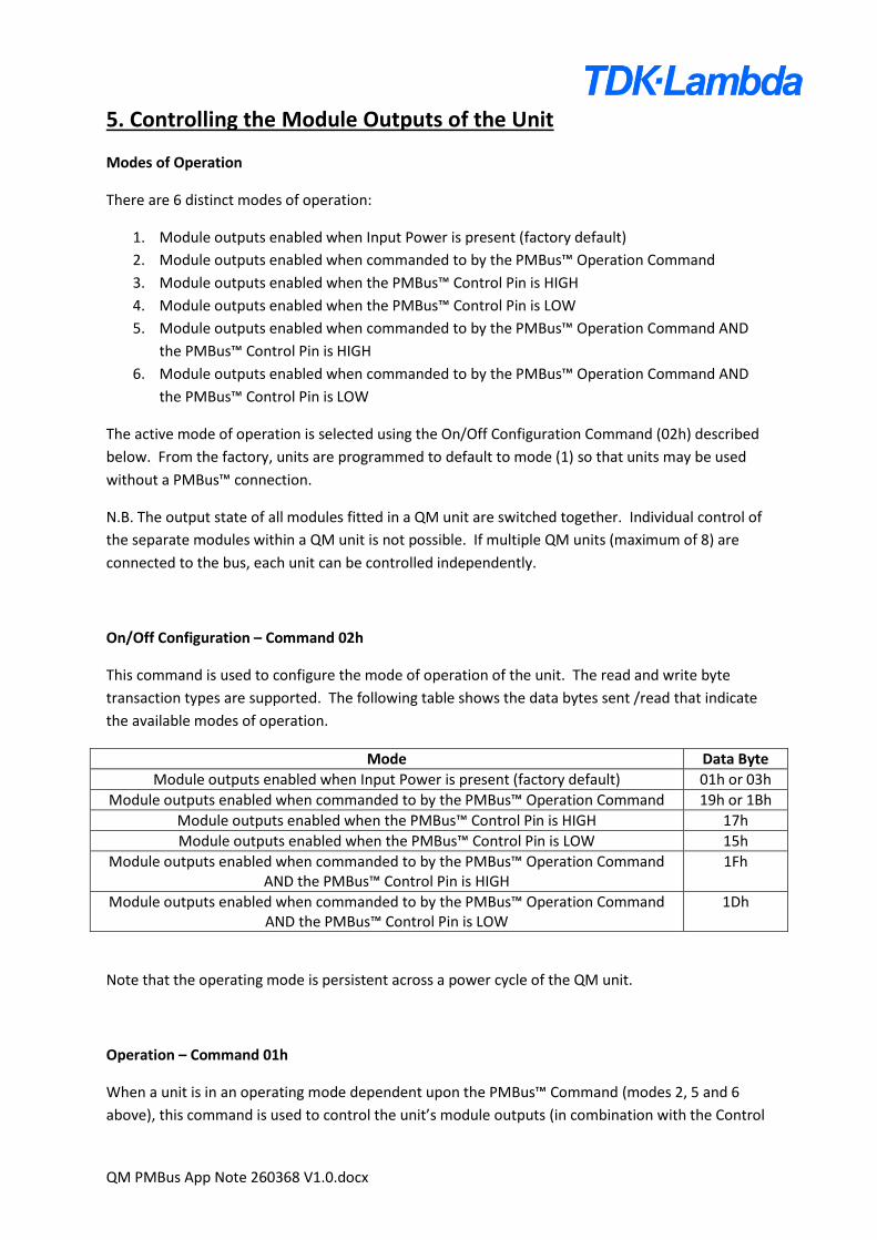
5. Controlling the Module Outputs of the Unit
Modes of Operation
There are 6 distinct modes of operation:
1. Module outputs enabled when Input Power is present (factory default)
2. Module outputs enabled when commanded to by the PMBus™ Operation Command
3. Module outputs enabled when the PMBus™ Control Pin is HIGH
4. Module outputs enabled when the PMBus™ Control Pin is LOW
5. Module outputs enabled when commanded to by the PMBus™ Operation Command AND
the PMBus™ Control Pin is HIGH
6. Module outputs enabled when commanded to by the PMBus™ Operation Command AND
the PMBus™ Control Pin is LOW
The active mode of operation is selected using the On/Off Configuration Command (02h) described
below. From the factory, units are programmed to default to mode (1) so that units may be used
without a PMBus™ connection.
N.B. The output state of all modules fitted in a QM unit are switched together. Individual control of
the separate modules within a QM unit is not possible. If multiple QM units (maximum of 8) are
connected to the bus, each unit can be controlled independently.
On/Off Configuration – Command 02h
This command is used to configure the mode of operation of the unit. The read and write byte
transaction types are supported. The following table shows the data bytes sent /read that indicate
the available modes of operation.
Mode Data Byte
Module outputs enabled when Input Power is present (factory default) 01h or 03h
Module outputs enabled when commanded to by the PMBus™ Operation Command 19h or 1Bh
Module outputs enabled when the PMBus™ Control Pin is HIGH 17h
Module outputs enabled when the PMBus™ Control Pin is LOW 15h
Module outputs enabled when commanded to by the PMBus™ Operation Command AND the PMBus™ Control Pin is HIGH
1Fh
Module outputs enabled when commanded to by the PMBus™ Operation Command AND the PMBus™ Control Pin is LOW
1Dh
Note that the operating mode is persistent across a power cycle of the QM unit.
Operation – Command 01h
When a unit is in an operating mode dependent upon the PMBus™ Command (modes 2, 5 and 6
above), this command is used to control the unit’s module outputs (in combination with the Control
QM PMBus App Note 260368 V1.0.docx
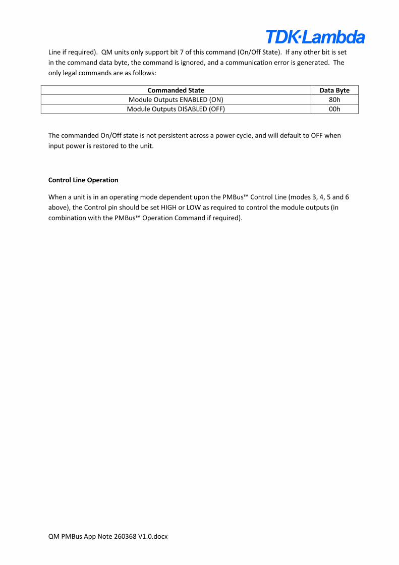
Line if required). QM units only support bit 7 of this command (On/Off State). If any other bit is set
in the command data byte, the command is ignored, and a communication error is generated. The
only legal commands are as follows:
Commanded State Data Byte
Module Outputs ENABLED (ON) 80h
Module Outputs DISABLED (OFF) 00h
The commanded On/Off state is not persistent across a power cycle, and will default to OFF when
input power is restored to the unit.
Control Line Operation
When a unit is in an operating mode dependent upon the PMBus™ Control Line (modes 3, 4, 5 and 6
above), the Control pin should be set HIGH or LOW as required to control the module outputs (in
combination with the PMBus™ Operation Command if required).
QM PMBus App Note 260368 V1.0.docx
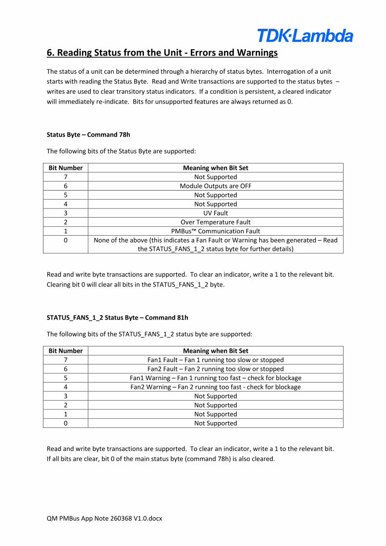
6. Reading Status from the Unit - Errors and Warnings
The status of a unit can be determined through a hierarchy of status bytes. Interrogation of a unit
starts with reading the Status Byte. Read and Write transactions are supported to the status bytes –
writes are used to clear transitory status indicators. If a condition is persistent, a cleared indicator
will immediately re-indicate. Bits for unsupported features are always returned as 0.
Status Byte – Command 78h
The following bits of the Status Byte are supported:
Bit Number Meaning when Bit Set
7 Not Supported
6 Module Outputs are OFF
5 Not Supported
4 Not Supported
3 UV Fault
2 Over Temperature Fault
1 PMBus™ Communication Fault
0 None of the above (this indicates a Fan Fault or Warning has been generated – Read the STATUS_FANS_1_2 status byte for further details)
Read and write byte transactions are supported. To clear an indicator, write a 1 to the relevant bit.
Clearing bit 0 will clear all bits in the STATUS_FANS_1_2 byte.
STATUS_FANS_1_2 Status Byte – Command 81h
The following bits of the STATUS_FANS_1_2 status byte are supported:
Bit Number Meaning when Bit Set
7 Fan1 Fault – Fan 1 running too slow or stopped
6 Fan2 Fault – Fan 2 running too slow or stopped
5 Fan1 Warning – Fan 1 running too fast – check for blockage
4 Fan2 Warning – Fan 2 running too fast - check for blockage
3 Not Supported
2 Not Supported
1 Not Supported
0 Not Supported
Read and write byte transactions are supported. To clear an indicator, write a 1 to the relevant bit.
If all bits are clear, bit 0 of the main status byte (command 78h) is also cleared.

QM PMBus App Note 260368 V1.0.docx
Clear Faults – Command 03h
Send byte transaction type. This command is used to clear all fault or warning indications in a single
transaction. If conditions are persistent, the errors or warnings will immediately re-indicate.
QM PMBus App Note 260368 V1.0.docx
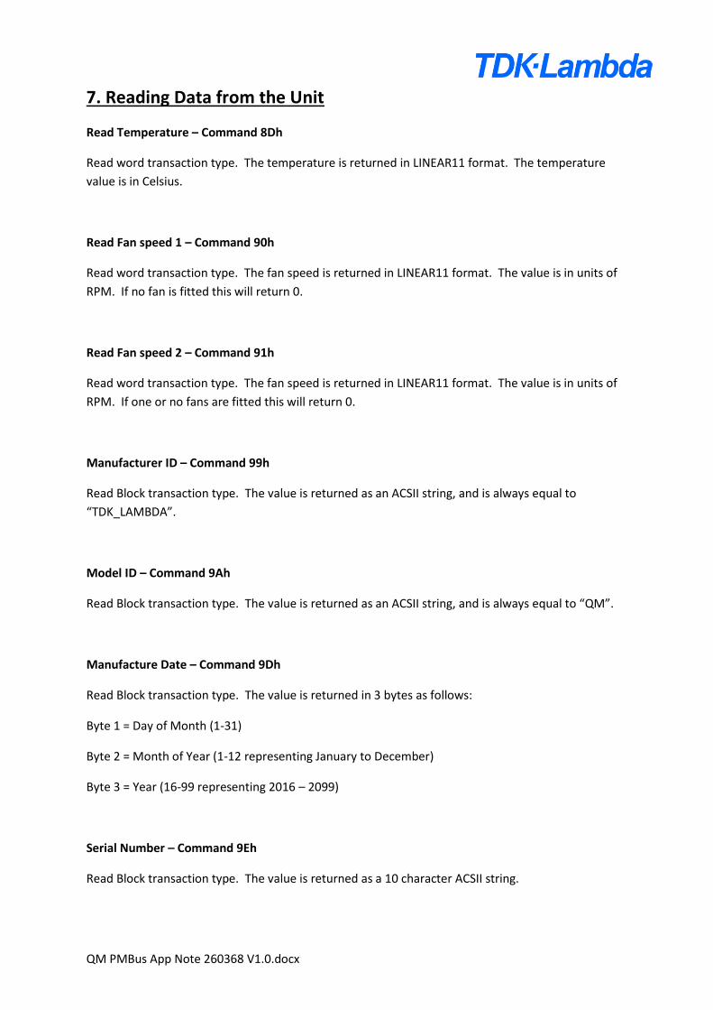
7. Reading Data from the Unit
Read Temperature – Command 8Dh
Read word transaction type. The temperature is returned in LINEAR11 format. The temperature
value is in Celsius.
Read Fan speed 1 – Command 90h
Read word transaction type. The fan speed is returned in LINEAR11 format. The value is in units of
RPM. If no fan is fitted this will return 0.
Read Fan speed 2 – Command 91h
Read word transaction type. The fan speed is returned in LINEAR11 format. The value is in units of
RPM. If one or no fans are fitted this will return 0.
Manufacturer ID – Command 99h
Read Block transaction type. The value is returned as an ACSII string, and is always equal to
“TDK_LAMBDA”.
Model ID – Command 9Ah
Read Block transaction type. The value is returned as an ACSII string, and is always equal to “QM”.
Manufacture Date – Command 9Dh
Read Block transaction type. The value is returned in 3 bytes as follows:
Byte 1 = Day of Month (1-31)
Byte 2 = Month of Year (1-12 representing January to December)
Byte 3 = Year (16-99 representing 2016 – 2099)
Serial Number – Command 9Eh
Read Block transaction type. The value is returned as a 10 character ACSII string.
QM PMBus App Note 260368 V1.0.docx
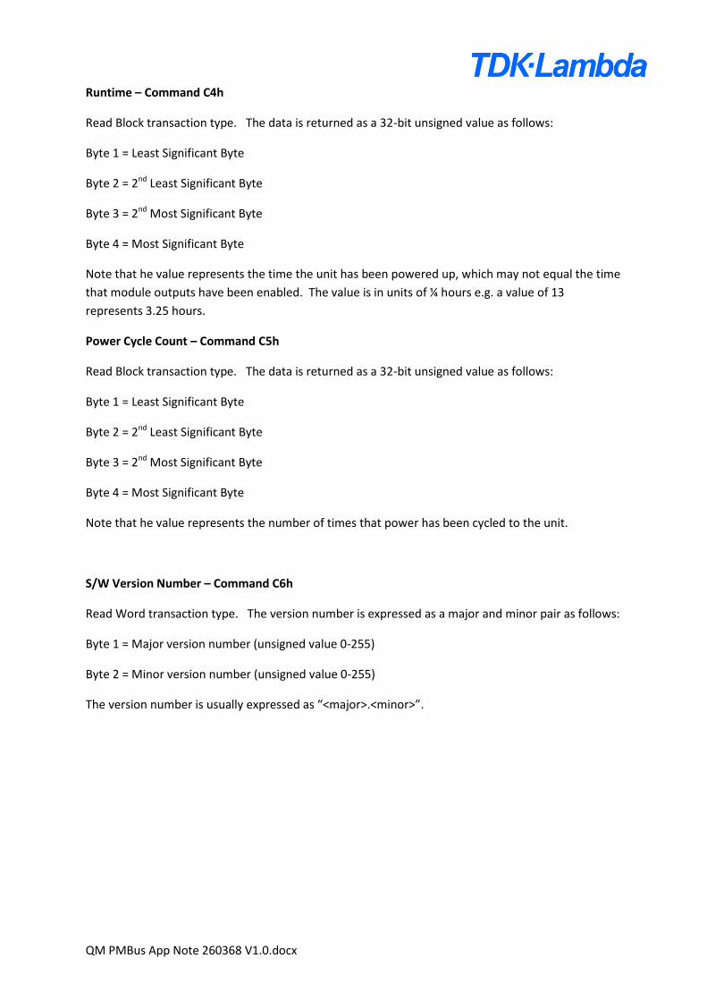
Runtime – Command C4h
Read Block transaction type. The data is returned as a 32-bit unsigned value as follows:
Byte 1 = Least Significant Byte
Byte 2 = 2nd Least Significant Byte
Byte 3 = 2nd Most Significant Byte
Byte 4 = Most Significant Byte
Note that he value represents the time the unit has been powered up, which may not equal the time
that module outputs have been enabled. The value is in units of ¼ hours e.g. a value of 13
represents 3.25 hours.
Power Cycle Count – Command C5h
Read Block transaction type. The data is returned as a 32-bit unsigned value as follows:
Byte 1 = Least Significant Byte
Byte 2 = 2nd Least Significant Byte
Byte 3 = 2nd Most Significant Byte
Byte 4 = Most Significant Byte
Note that he value represents the number of times that power has been cycled to the unit.
S/W Version Number – Command C6h
Read Word transaction type. The version number is expressed as a major and minor pair as follows:
Byte 1 = Major version number (unsigned value 0-255)
Byte 2 = Minor version number (unsigned value 0-255)
The version number is usually expressed as “<major>.<minor>”.
QM PMBus App Note 260368 V1.0.docx
8. Miscellaneous Commands
Capability – Command 19h
Read byte transaction type. The value returned represents the capability of the PMBus™
implementation. A fixed value is returned by QM units of 80h. This indicates:
PEC Supported
100kHz Max Speed
SMBAlert Not Supported
Numeric Format LINEAR11
AVSBus™ Not Supported
PMBus™ Revision – Command 98h
Read byte transaction type. The value returned represents the PMBus™ revision supported. A fixed
value is returned by QM units of 33h. This indicates that the units support PMBus™ version 1.3.
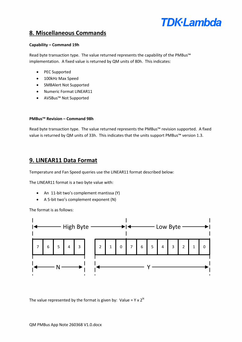
9. LINEAR11 Data Format
Temperature and Fan Speed queries use the LINEAR11 format described below:
The LINEAR11 format is a two byte value with:
An 11-bit two’s complement mantissa (Y)
A 5-bit two’s complement exponent (N)
The format is as follows:
7 6 5 4 3 2 1 0 7 6 5 4 3 2 1 0
High Byte Low Byte
N Y
The value represented by the format is given by: Value = Y x 2N
QM PMBus App Note 260368 V1.0.docx
10. Recommended Operation
Following a command or query to a unit, the Status Byte should be read to determine if a
communication error occurred during the transaction. If a communication error occurred (as
indicated by Bit 1 of the Status Byte being set) it should be assumed that the command was not
actioned, or the data returned is not valid. The communication error status should then be cleared
by writing a 1 to Bit 1 of the Status Byte, followed by a read of the Status Byte to check that it’s clear.
The command or query should then be repeated and the Status Byte rechecked until no error is
reported during the transaction.
11. General Notes
SMBAlert is not supported.
The PMBus™ Group Command is not supported.
PEC (Packet Error Checking) is supported and should be used.
If simultaneous control of the module outputs from multiple QM units is required, this may be
achieved using the PMBus™ Control Pin which may be routed to all units. It should be noted that
due to differences in module output start-up times, precise synchronisation cannot be guaranteed.
QM units operate as a slave in single master systems only.
A maximum of 8-units may be connected to the bus, each unit must have a unique PMBus™ address.
12. Recommended PMBus™ Interface Adapter
The following USB to PMBus™ adapter is recommended:
Manufacturer: Texas Instruments
Manufacturer Part Number: USB-TO-GPIO
This is available from many suppliers, for example:
Farnell order Code: 1901883
Digi-Key Part Number: 296-23114-ND
RS Stock Number: 819-7562
Mouser Part Number: 595-USB-TO-GPIO
QM PMBus App Note 260368 V1.0.docx
13. References
Ref[1]: System Management Bus (SMBus) Specification. Version 3.0, 20 Dec 2014.
Ref[2]: PMBus™ Power System Management Protocol Specification Part 1 – General Requirements,
Transport And Electrical Interface. Revision 1.3.1, 13th March 2015.
Ref[3]: PMBus™ Power System Management Protocol Specification Part II – Command Language.
Revision 1.3.1, 13th March 2015.