Embed Size (px)
Citation preview
Project Management Methodology (PMM) &
Software Development Life Cycle (SDLC) Guide
Mike McCormick
February 2014
PMM & SDLC Guide
Table of Contents
Introduction ............................................................................................................................... 1
Systems Development Life Cycle (SDLC) .............................................................................. 2
How does the SDLC integrate with the PMM? ........................................................................ 4
SDLC Phases ............................................................................................................................ 5
4.1.2.1 Requirements Validation and Definition ...................................................................... 5
4.1.2.2 Analysis and Design Phase: General System Design ................................................. 9
4.1.2.2 Analysis and Design Phase: Detailed System Design .............................................. 20
4.1.2.3 Development Phase .................................................................................................. 24
4.1.2.4 Testing and Quality Assurance Phase ...................................................................... 26
4.1.2.5 Accept and Install Phase ........................................................................................... 28
About the Author
Michael McCormick - Management Professional with 39 years of experience managing over $4 billion in programs & projects for both the Commercial and Federal Government sectors and is a well known project management (PM) author, consultant, and authority on the subjects of Construction Management (CM), Facility Management (FM), Business Process Management (BPM), Project Management Office (PMO), Project Portfolio Management (PPM), Risk Management (RM), software development and technology integration.
www.mccormickpcs.com
Page | 1
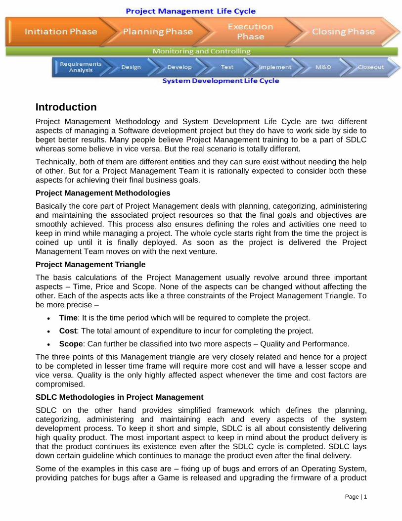
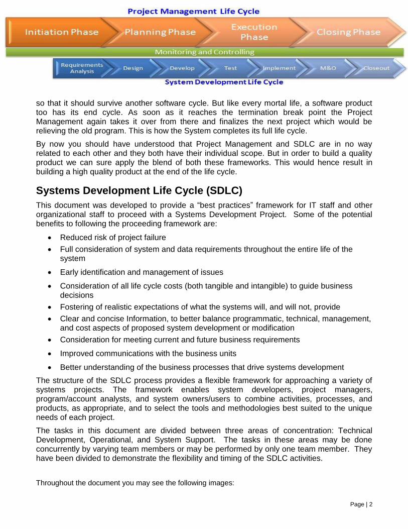
Introduction
Project Management Methodology and System Development Life Cycle are two different aspects of managing a Software development project but they do have to work side by side to beget better results. Many people believe Project Management training to be a part of SDLC whereas some believe in vice versa. But the real scenario is totally different.
Technically, both of them are different entities and they can sure exist without needing the help of other. But for a Project Management Team it is rationally expected to consider both these aspects for achieving their final business goals.
Project Management Methodologies
Basically the core part of Project Management deals with planning, categorizing, administering and maintaining the associated project resources so that the final goals and objectives are smoothly achieved. This process also ensures defining the roles and activities one need to keep in mind while managing a project. The whole cycle starts right from the time the project is coined up until it is finally deployed. As soon as the project is delivered the Project Management Team moves on with the next venture.
Project Management Triangle
The basis calculations of the Project Management usually revolve around three important aspects – Time, Price and Scope. None of the aspects can be changed without affecting the other. Each of the aspects acts like a three constraints of the Project Management Triangle. To be more precise –
Time: It is the time period which will be required to complete the project.
Cost: The total amount of expenditure to incur for completing the project.
Scope: Can further be classified into two more aspects – Quality and Performance.
The three points of this Management triangle are very closely related and hence for a project to be completed in lesser time frame will require more cost and will have a lesser scope and vice versa. Quality is the only highly affected aspect whenever the time and cost factors are compromised.
SDLC Methodologies in Project Management
SDLC on the other hand provides simplified framework which defines the planning, categorizing, administering and maintaining each and every aspects of the system development process. To keep it short and simple, SDLC is all about consistently delivering high quality product. The most important aspect to keep in mind about the product delivery is that the product continues its existence even after the SDLC cycle is completed. SDLC lays down certain guideline which continues to manage the product even after the final delivery.
Some of the examples in this case are – fixing up of bugs and errors of an Operating System, providing patches for bugs after a Game is released and upgrading the firmware of a product
Page | 2
so that it should survive another software cycle. But like every mortal life, a software product too has its end cycle. As soon as it reaches the termination break point the Project Management again takes it over from there and finalizes the next project which would be relieving the old program. This is how the System completes its full life cycle.
By now you should have understood that Project Management and SDLC are in no way related to each other and they both have their individual scope. But in order to build a quality product we can sure apply the blend of both these frameworks. This would hence result in building a high quality product at the end of the life cycle.
Systems Development Life Cycle (SDLC)
This document was developed to provide a “best practices” framework for IT staff and other organizational staff to proceed with a Systems Development Project. Some of the potential benefits to following the proceeding framework are:
Reduced risk of project failure
Full consideration of system and data requirements throughout the entire life of the system
Early identification and management of issues
Consideration of all life cycle costs (both tangible and intangible) to guide business decisions
Fostering of realistic expectations of what the systems will, and will not, provide
Clear and concise Information, to better balance programmatic, technical, management, and cost aspects of proposed system development or modification
Consideration for meeting current and future business requirements
Improved communications with the business units
Better understanding of the business processes that drive systems development
The structure of the SDLC process provides a flexible framework for approaching a variety of systems projects. The framework enables system developers, project managers, program/account analysts, and system owners/users to combine activities, processes, and products, as appropriate, and to select the tools and methodologies best suited to the unique needs of each project.
The tasks in this document are divided between three areas of concentration: Technical Development, Operational, and System Support. The tasks in these areas may be done concurrently by varying team members or may be performed by only one team member. They have been divided to demonstrate the flexibility and timing of the SDLC activities.
Throughout the document you may see the following images:
Page | 3
= Important note or checkpoint in the process
=
Represents a deliverable or an output from the process steps
Page | 4
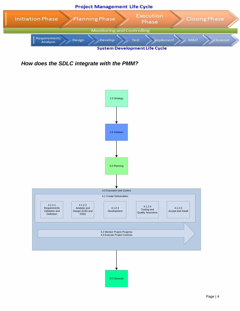
How does the SDLC integrate with the PMM?
1.0 Strategy
2.0 Initiation
3.0 Planning
5.0 Closeout
4.0 Execution and Control
4.2 Monitor Project Progress
4.3 Execute Project Controls
4.1 Create Deliverables
4.1.2.1
Requirements
Validation and
Definition
4.1.2.2
Analysis and
Design (GSD and
DSD)
4.1.2.3
Development
4.1.2.4
Testing and
Quality Assurance
4.1.2.5
Accept and Install
Page | 5
SDLC Phases
4.1.2.1 Requirements Validation and Definition
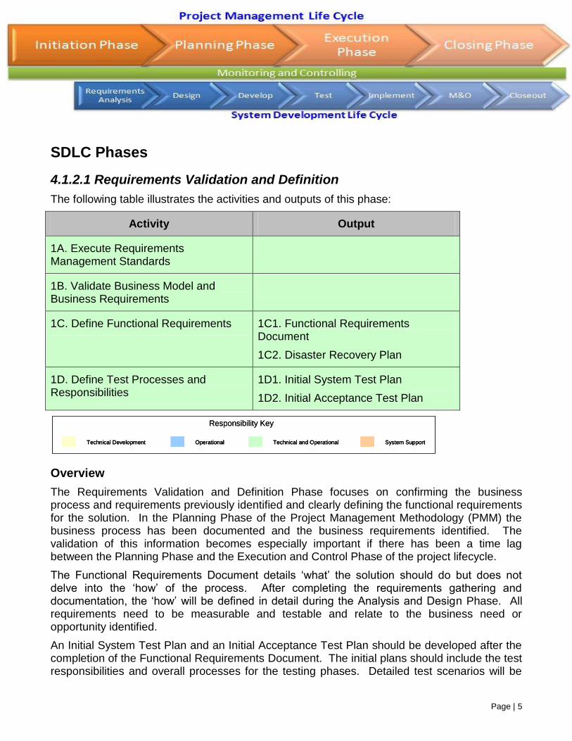
The following table illustrates the activities and outputs of this phase:
Activity Output
1A. Execute Requirements Management Standards
1B. Validate Business Model and Business Requirements
1C. Define Functional Requirements 1C1. Functional Requirements Document
1C2. Disaster Recovery Plan
1D. Define Test Processes and Responsibilities
1D1. Initial System Test Plan
1D2. Initial Acceptance Test Plan
Overview
The Requirements Validation and Definition Phase focuses on confirming the business process and requirements previously identified and clearly defining the functional requirements for the solution. In the Planning Phase of the Project Management Methodology (PMM) the business process has been documented and the business requirements identified. The validation of this information becomes especially important if there has been a time lag between the Planning Phase and the Execution and Control Phase of the project lifecycle.
The Functional Requirements Document details ‘what’ the solution should do but does not delve into the ‘how’ of the process. After completing the requirements gathering and documentation, the ‘how’ will be defined in detail during the Analysis and Design Phase. All requirements need to be measurable and testable and relate to the business need or opportunity identified.
An Initial System Test Plan and an Initial Acceptance Test Plan should be developed after the completion of the Functional Requirements Document. The initial plans should include the test responsibilities and overall processes for the testing phases. Detailed test scenarios will be
Technical Development Operational Technical and Operational System Support
Responsibility Key
Technical DevelopmentTechnical Development OperationalOperational Technical and OperationalTechnical and Operational System SupportSystem Support
Responsibility Key
Page | 6
incorporated into the final plans (completed in the Analysis and Design, and Development Phases).
In addition, the project team should use the Data Recovery and Backup Requirements collected in order to create a Disaster Recovery Plan. The Disaster Recovery Plan is an essential document for the ongoing success of a solution. If there is an organizational Disaster Recovery Plan, the project team must ensure that the solution is integrated into the existing plan.
1A. Execute Requirements Management Standards
Created in the Planning Phase of the Project Management Methodology (PMM), the Requirements Management Plan outlines the methods of gathering requirements as well as the procedures for maintaining those requirements.
It is the responsibility of the project manager to ensure that the project team is aware of and implements the plan, the process and the associated responsibilities.
1B. Validate Business Model and Business Requirements
Created in the Planning Phase of the PMM, the Business Requirements document (which may include Business Process models) should be validated. Any changes that may have occurred to the business process should be incorporated into the documentation. If new requirements have been identified, the PMM Change Control process should be followed to determine if the new requirement will be incorporated into the solution.
1C. Define System Requirements
During Requirements Definition, the system is described in detail with regard to system inputs, processes, outputs, and interfaces; this definition process occurs at the functional level. Functional user requirements are formally defined and delineate the requirements in terms of data, system performance, security, and maintainability requirements. Requirements are defined to a level of detail sufficient for systems design to proceed. The emphasis in requirements gathering and analysis is on determining what functions must be performed rather than how to perform those functions. All requirements also need to be measurable and testable and relate to the business need or opportunity described by the business unit.
A variety of requirement analysis techniques can be used alone or in combination with other techniques, to gather, document and verify the requirements.
1C1. Updated Requirements Document
The purpose of the updated Requirements Document is to complete the foundation for the design and development of a technical solution that began with the business requirements elicited and documented during the Planning Phase. The Business Requirements describe the high-level business process and also outlines the business needs that will be fulfilled by the
Page | 7
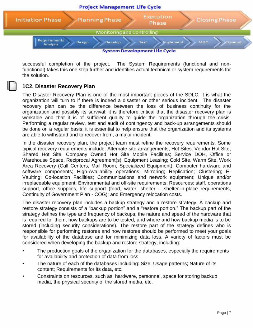
successful completion of the project. The System Requirements (functional and non-functional) takes this one step further and identifies actual technical or system requirements for the solution.
1C2. Disaster Recovery Plan
The Disaster Recovery Plan is one of the most important pieces of the SDLC; it is what the organization will turn to if there is indeed a disaster or other serious incident. The disaster recovery plan can be the difference between the loss of business continuity for the organization and possibly its survival; it is therefore critical that the disaster recovery plan is workable and that it is of sufficient quality to guide the organization through the crisis. Performing a regular review, test and audit of contingency and back-up arrangements should be done on a regular basis; it is essential to help ensure that the organization and its systems are able to withstand and to recover from, a major incident.
In the disaster recovery plan, the project team must refine the recovery requirements. Some typical recovery requirements include: Alternate site arrangements; Hot Sites: Vendor Hot Site, Shared Hot Site, Company Owned Hot Site Mobile Facilities; Service DOH, Office or Warehouse Space, Reciprocal Agreement(s), Equipment Leasing; Cold Site, Warm Site, Work Area Recovery (Call Centers, Mail Room, Specialized Equipment); Computer hardware and software components; High-Availability operations; Mirroring; Replication; Clustering; E-Vaulting; Co-location Facilities; Communications and network equipment; Unique and/or irreplaceable equipment; Environmental and off-site requirements; Resources: staff, operations support, office supplies, life support (food, water, shelter – shelter-in-place requirements, Continuity of Government Plan - COG); and Emergency relocation costs.
The disaster recovery plan includes a backup strategy and a restore strategy. A backup and restore strategy consists of a “backup portion” and a “restore portion.” The backup part of the strategy defines the type and frequency of backups, the nature and speed of the hardware that is required for them, how backups are to be tested, and where and how backup media is to be stored (including security considerations). The restore part of the strategy defines who is responsible for performing restores and how restores should be performed to meet your goals for availability of the database and for minimizing data loss. A variety of factors must be considered when developing the backup and restore strategy, including:
• The production goals of the organization for the databases, especially the requirements for availability and protection of data from loss
• The nature of each of the databases including: Size; Usage patterns; Nature of its content; Requirements for its data, etc.
• Constraints on resources, such as: hardware, personnel, space for storing backup media, the physical security of the stored media, etc.
Page | 8
1D. Define Test Processes and Responsibilities
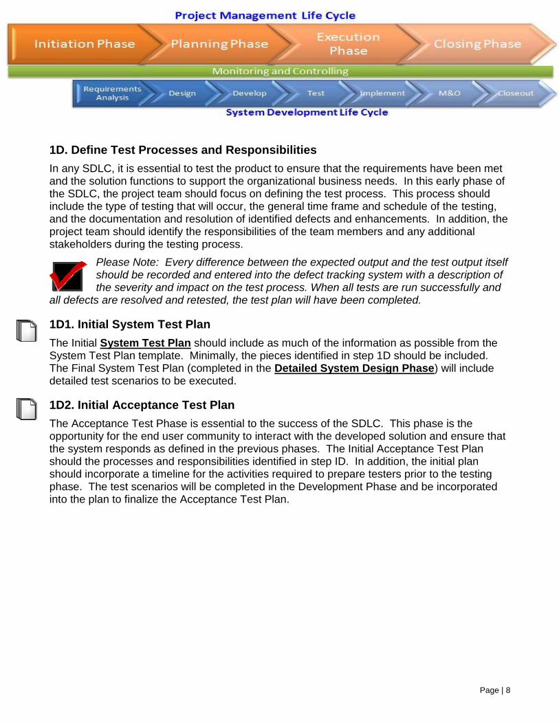
In any SDLC, it is essential to test the product to ensure that the requirements have been met and the solution functions to support the organizational business needs. In this early phase of the SDLC, the project team should focus on defining the test process. This process should include the type of testing that will occur, the general time frame and schedule of the testing, and the documentation and resolution of identified defects and enhancements. In addition, the project team should identify the responsibilities of the team members and any additional stakeholders during the testing process.
Please Note: Every difference between the expected output and the test output itself should be recorded and entered into the defect tracking system with a description of the severity and impact on the test process. When all tests are run successfully and
all defects are resolved and retested, the test plan will have been completed.
1D1. Initial System Test Plan
The Initial System Test Plan should include as much of the information as possible from the System Test Plan template. Minimally, the pieces identified in step 1D should be included. The Final System Test Plan (completed in the Detailed System Design Phase) will include detailed test scenarios to be executed.
1D2. Initial Acceptance Test Plan
The Acceptance Test Phase is essential to the success of the SDLC. This phase is the opportunity for the end user community to interact with the developed solution and ensure that the system responds as defined in the previous phases. The Initial Acceptance Test Plan should the processes and responsibilities identified in step ID. In addition, the initial plan should incorporate a timeline for the activities required to prepare testers prior to the testing phase. The test scenarios will be completed in the Development Phase and be incorporated into the plan to finalize the Acceptance Test Plan.
Page | 9
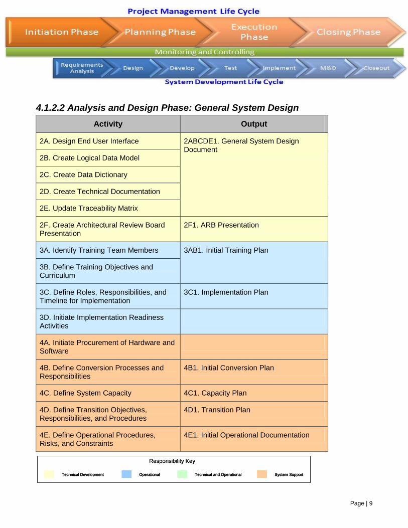
4.1.2.2 Analysis and Design Phase: General System Design
Activity Output
2A. Design End User Interface 2ABCDE1. General System Design Document
2B. Create Logical Data Model
2C. Create Data Dictionary
2D. Create Technical Documentation
2E. Update Traceability Matrix
2F. Create Architectural Review Board Presentation
2F1. ARB Presentation
3A. Identify Training Team Members 3AB1. Initial Training Plan
3B. Define Training Objectives and Curriculum
3C. Define Roles, Responsibilities, and Timeline for Implementation
3C1. Implementation Plan
3D. Initiate Implementation Readiness Activities
4A. Initiate Procurement of Hardware and Software
4B. Define Conversion Processes and Responsibilities
4B1. Initial Conversion Plan
4C. Define System Capacity 4C1. Capacity Plan
4D. Define Transition Objectives, Responsibilities, and Procedures
4D1. Transition Plan
4E. Define Operational Procedures, Risks, and Constraints
4E1. Initial Operational Documentation
Technical Development Operational Technical and Operational System Support
Responsibility Key
Technical DevelopmentTechnical Development OperationalOperational Technical and OperationalTechnical and Operational System SupportSystem Support
Responsibility Key
Page | 10
Overview
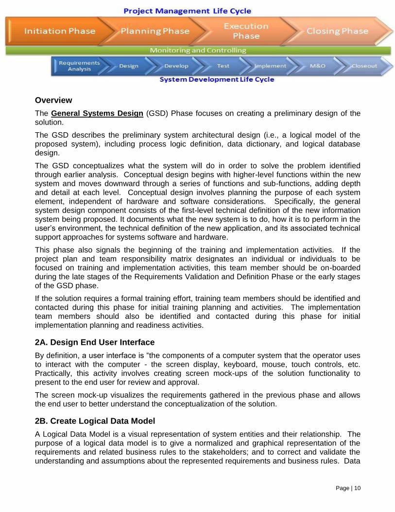
The General Systems Design (GSD) Phase focuses on creating a preliminary design of the solution.
The GSD describes the preliminary system architectural design (i.e., a logical model of the proposed system), including process logic definition, data dictionary, and logical database design.
The GSD conceptualizes what the system will do in order to solve the problem identified through earlier analysis. Conceptual design begins with higher-level functions within the new system and moves downward through a series of functions and sub-functions, adding depth and detail at each level. Conceptual design involves planning the purpose of each system element, independent of hardware and software considerations. Specifically, the general system design component consists of the first-level technical definition of the new information system being proposed. It documents what the new system is to do, how it is to perform in the user’s environment, the technical definition of the new application, and its associated technical support approaches for systems software and hardware.
This phase also signals the beginning of the training and implementation activities. If the project plan and team responsibility matrix designates an individual or individuals to be focused on training and implementation activities, this team member should be on-boarded during the late stages of the Requirements Validation and Definition Phase or the early stages of the GSD phase.
If the solution requires a formal training effort, training team members should be identified and contacted during this phase for initial training planning and activities. The implementation team members should also be identified and contacted during this phase for initial implementation planning and readiness activities.
2A. Design End User Interface
By definition, a user interface is “the components of a computer system that the operator uses to interact with the computer - the screen display, keyboard, mouse, touch controls, etc. Practically, this activity involves creating screen mock-ups of the solution functionality to present to the end user for review and approval.
The screen mock-up visualizes the requirements gathered in the previous phase and allows the end user to better understand the conceptualization of the solution.
2B. Create Logical Data Model
A Logical Data Model is a visual representation of system entities and their relationship. The purpose of a logical data model is to give a normalized and graphical representation of the requirements and related business rules to the stakeholders; and to correct and validate the understanding and assumptions about the represented requirements and business rules. Data
Page | 11
modeling, as a discipline can be done through various technical tools including the Microsoft Office Suite.
For a better understanding of data modeling and some examples, please refer to http://www.agiledata.org/essays/dataModeling101.html.
2C. Create Data Dictionary
A Data Dictionary is a set of metadata that contains definitions and representations of the data elements; it is also a file that defines the basic organization of a database. The data dictionary includes but is not limited to the table name (for the individual field), the field name, the field description, the data type, the field size, the primary key, and the default value.
2D. Create Technical Documentation
Technical documentation refers to the documentation created for the solution artifacts. Unlike the operational documentation, the technical documentation outlines the intent of and execution of the design. This documentation will be a significant portion of the Design Baseline (created at the beginning of the Development Phase). It allows various developers to reference the same detailed information to allow for the consistent and accurate implementation of the requirements. Two possible examples for this documentation would be Unified Modeling Language (UML) including Use Cases, Sequence, Class, and Activity Diagrams and Process Model Narratives (a detailed narrative of the solution components).
2E. Update Traceability Matrix
A traceability matrix is created by associating requirements with the work products that satisfy them. Tests are associated with the requirements on which they are based and the product tested to meet the requirement.
Traceability ensures completeness, that all lower level requirements come from higher level requirements, and that all higher level requirements are allocated to lower level requirements. Traceability is also used to manage change and provides the basis for test planning.
The Traceability Matrix, created in the Planning Phase of the PMM, should be updated with the design elements (objects) that will satisfy the identified requirements.
2ABCDE1. General System Design Document
The General Systems Design Document describes the high level design specifications for the system under development. It describes how the application will be constructed, by specifying the components to be used, how they will be organized in relation to each other, and the general principles of the application's internal construction.
Page | 12
It should incorporate all the information created and/or updated in Steps 2A, 2B, 2C, 2D, and 2E.
2F. Complete Architectural Review Board Checklist and Presentation
The Architecture Review Board is typically accountable to an Executive Board which delegates to it the design of a coherent Enterprise Architecture and the establishment, maintenance and enforcement of Business and IT Strategy throughout an organization.
The main functions and responsibilities of the Architecture Review Board are primarily to:
Establish, own and manage the content of the Enterprise Architecture Strategy (i.e. principles, standards, policies, guidelines and reference models) applicable to IT components under the responsibility of an organization.
Enforce compliance of IT designs and components (including IT infrastructures, systems and applications) with the Enterprise Architecture Strategy.
Decide on possible exceptions to be granted to request for deviations from the Enterprise Architecture Strategy and act as ultimate escalation point on matters related to its mandate.
Communicate the Enterprise Architecture Strategy throughout an organization, so as to improve the maturity level of architecture discipline within an organization.
Establishing an Architecture Review Board
In my last post I talked about the definition of an Architecture Review Board (ARB), let’s talk now about what it means to create one. As we talked about in the last post, establishing an Architecture Review Board (ARB) is the best way to facilitate how IT decisions are made across the enterprise. Eliminating the behavior of making architectural discussions in a vacuum and providing visibility to how and why IT decisions are made. If done right, this should result in proactive decision making and raising the education across the enterprise on architecture trade-off analysis.
Keep in mind that establishing an ARB is often times a challenging feat. Introducing this function will affect the core of your Software Development Life Cycle’s (SDLC). This has the potential of touching everyone in the organization, so it is important to get it right.
If an ARB is new to you and makes sense to your organization there are some preliminary activities you are going to want to do in the beginning. Just like with most things in the architecture world you will have to sell, sell, sell…
It is very important that one of the first things you do is to ensure that your approach is bought into by the executive leadership team such as VP’s, CTO’s and CIO’s. Do this early and continue to engage all through the process. Their buy-in will ensure that your ARB get’s top down support.
Page | 13
Establishing support from the top isn’t the only support you will need. Gaining the support of the architecture community within your organization is vital. However, to get things rolling in the right direction you will need to establish the accountabilities and the process frameworks that are fully endorsed by your CIO.
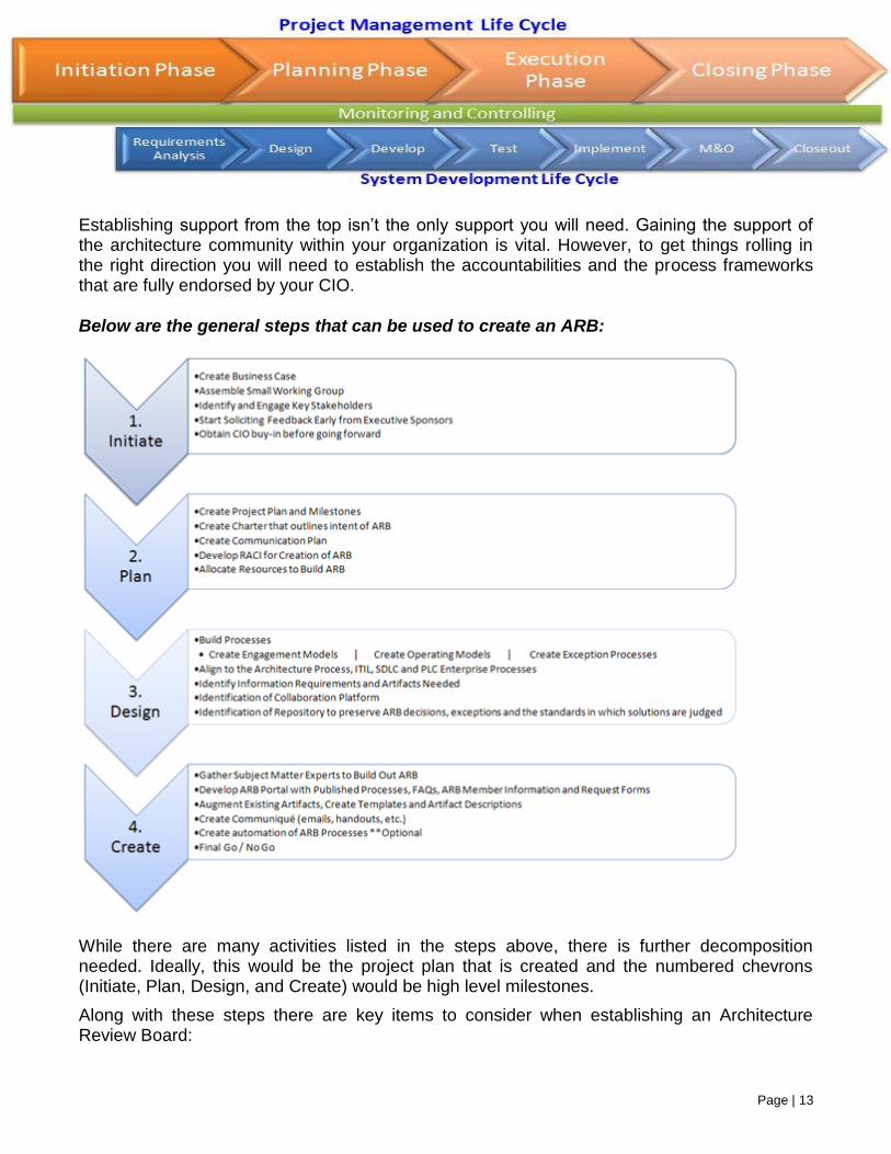
Below are the general steps that can be used to create an ARB:
While there are many activities listed in the steps above, there is further decomposition needed. Ideally, this would be the project plan that is created and the numbered chevrons (Initiate, Plan, Design, and Create) would be high level milestones.
Along with these steps there are key items to consider when establishing an Architecture Review Board:
Page | 14
1. Build the Case – This is your business case proposal to present to senior management. This is usually in the form of a PowerPoint deck that delivers the key points at a level that senior management wants to see. It should contain the value of such a board. Understanding what Key Performance Indicators (KPI’s) should be derived will aid in your proposal. You should specifically get ahead of some common questions regarding overhead and bureaucracy.
2. Do Just Enough ARB - Determine your Enterprise Architecture Capability and IT Organizational maturity to derive how your ARB will function. Remember, you should have a multi-program approach to the ARB. You will not achieve the desired state overnight.
3. Gap Analysis - Align ARB with the current governance structure and determine gaps that should be filled. Keep your eye on the high value, low friction items to tackle first in the beginning.
4. Communicate - Build the ARB Communication Plan and keep to it. It is critical, especially in the creation of the ARB framework to keep stakeholders and customers of the progress and decisions for the board. After the creation of the ARB it will be important to send out communications of decisions, value demonstrated and key developments of the board framework.
2F1. Architecture Review Board Presentation Guidelines
The application project manager typically submits a presentation package to the ARB Chairperson one week prior to the scheduled ARB meeting. The ARB chairperson will distribute the presentation package to the ARB for review.
The application project manager typically is responsible for having a Program Office Sponsor attend the ARB presentation. The application project manager is also responsible for obtaining the approval of the AR Checklist and ARB Presentation by the Project Sponsor and their department supervisor prior to the ARB meeting.
Immediately following the review meeting, the ARB typically makes a recommendation to the CIO for approval or rejection of the proposed application architecture. One of the three decisions described below will result from the first ARB meeting.
If the ARB and the CIO unconditionally approves, detailed design can begin.
If the ARB and the CIO conditionally approves, detailed design can begin but the recommended ARB changes must be incorporated into the design.
If the ARB and the CIO rejects the proposed architecture, the application team must re-examine and return to the ARB with a revised design and architecture review packet.
3A. Identify Training Team Members
Page | 15
3B. Define Training Objectives and Curriculum
3AB1. Initial Training Plan
The Training Plan outlines the objectives, needs, strategy, and curriculum to be addressed when training users on the new or enhanced information system. The plan presents the activities needed to support the development of training materials, coordination of training schedules, reservation of personnel and facilities, planning for training needs, and other training-related tasks. It includes the approach to and the format of the training program, the list of topics to be covered, materials, time, space requirements, and proposed schedules.
3C. Define Roles, Responsibilities, and Timeline for Implementation
3C1. Implementation Plan
The Implementation Plan describes how the solution will be delivered to the end user, including any special requirements such as stage implementation or "roll out", training and delivery requirements.
3D. Initiate Implementation Readiness Activities
The implementation of any new system requires the careful planning and orchestration of activities to guide the implementation of the success of the project. The Implementation Readiness Activities provide a roadmap for the activities necessary to ensure the successful implementation of the solution.
Some of the implementation readiness activities may include:
Business Process Review and Reengineering (if not already completed)
Change Management Process Review
Site Assessments and Readiness Reviews
Coordinate and Assist with User Acceptance Testing
Training Planning and Execution
Pilot Implementation and System Roll-Out
Helpdesk Implementation
Change Control Procedures and User Groups
Transition to Maintenance and Ongoing Improvement
Effective systems implementation requires coordination that is disciplined, planned and well documented.
4A. Initiate Procurement of Hardware and Software
Page | 16
As outlined in the Procurement Plan and the Project Plan, any necessary hardware and software should be procured during this phase. Based on the procurement vehicle selected, it may be necessary to begin this process earlier in the SDLC. Please use procurement knowledge and lessons learned to determine the most appropriate time in the project lifecycle to begin procurement.
4B. Define Conversion Processes and Responsibilities
To successfully migrate a business unit’s data from one environment to another, conversion processes and responsibilities must be identified. If a standard conversion approach has been identified, the project should ensure its compliance. If there is no standard available, the approach and the activities of the various stakeholder groups should be outlined.
4B1. Initial Conversion Plan
The Conversion Plan describes the strategies involved in converting data from an existing system to another hardware or software environment.
Depending on the factors that must be considered for each system, the conversion plan should:
Describe any portion of the conversion process that should be performed manually
Indicate whether parallel runs of the old and new systems will be necessary during the conversion process
Describe the function of the data in the old system to assist in determining if the use will be the same or different in the new system
Indicate the order in which data is processed
Describe volume considerations such as the size of the database; amount of data to be converted; number of ‘reads’; time required for conversions
Define the work and delivery schedules; time-frame for reports; etc.
Describe data availability and indicate if data use should be limited during the conversion process
Indicate the disposition process for any obsolete data or data that is not converted
4C. Define System Capacity
Capacity Planning is the science and art of estimating the space, computer hardware, software and connection infrastructure resources that will be needed over some future period of time. The goal of capacity planning is to provide satisfactory service levels to users in a cost-effective manner.
Page | 17
Capacity Planning Process:
1. Determine service level requirements
a. Define workloads
b. Determine the unit of work
c. Identify service levels for each workload
2. Analyze current system capacity
a. Measure service levels and compare to objectives
b. Measure overall resource usage
c. Measure resource usage by workload
d. Identify components of response time
3. Plan for the future
a. Determine future processing requirements
b. Plan future system configuration
4C1. Capacity Plan
The Capacity Plan describes the following information; so that appropriate system hardware/resources can be put in place prior to when it will be required, but within the current 12-months:
1. Estimate increases or decreases in the number of end-users (to include county users, application developers, technical support personnel, Agency end-users, etc.) that will be accessing the Agency’s computing environment in using either existing applications or planned new applications.
2. Estimate the increase or decrease in the percentage of CPU utilization, host, server or workstation memory utilization, disk storage capacity consumption and or tape subsystem usage that may occur as a result of changes being made to existing applications in production.
3. Estimate the increase in the percentage of CPU utilization, host, server or workstation memory utilization, disk storage capacity consumption and or tape subsystem usage that may occur as a result of new applications being put into production.
4. Estimate the increase or decrease in online transactions anticipated in response to changes being made to existing applications in production, or for new applications to be placed into production.
Page | 18
5. For new applications (batch or online) identify the time of day and frequency (daily, weekly, quarterly, yearly) when these will be run, as well as the timing of any anticipated peak application usage.
6. Description of anticipated changes to existing backup requirements.
7. Description of desired or required changes to existing availability requirements for existing applications.
4D. Define Transition Objectives, Responsibilities, and Procedures
When a technical solution is developed and tested, an organization should establish objectives, responsibilities, and procedures for migrating the development code from one environment to another. If the organization has an existing Transition Plan, the project should ensure compliance with the standard.
4D1. Transition Plan
The Transition Process consists of Transition Plan, Transition Checklist, and Go Live Checklist which are meant to complement other detailed plans that are part of the standard life cycle (i.e. test plans (stress, UAT, regression), disaster recovery/business continuity plan, conversion plan, and similar. What is important is that the transition is thoroughly planned, documented and executed
Transition Planning is an iterative process that begins during the Planning stage and continues until the product/service is formally transitioned and accepted by the support organization and the Client. The outputs are dependent upon the nature of the project and tightly coupled with the System Development Life Cycle (SDLC) being used. The project manager is typically responsible for formulating the required plans to implement and support the products/services.
4E. Define Operational Procedures, Risks, and Constraints
Operational procedures are the tasks required to effectively maintain a technical solution. The support environment, the roles and responsibilities of personnel, and the regular activities essential to the support and maintenance of the application, workflows, and database activities should be defined. In addition, risks to ongoing operations and organizational constraints should be identified.
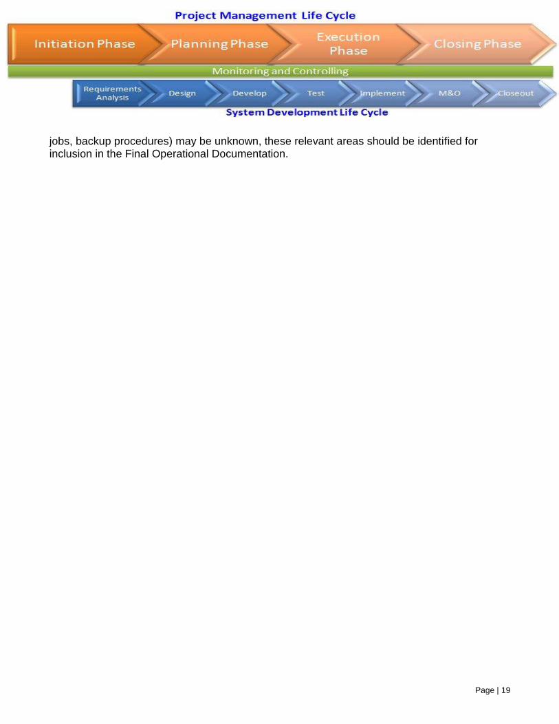
4E1. Initial Operational Documentation
The Initial Operational Documentation should contain, minimally, an outline of the information collected in the previous step. While detailed information about solution operations (e.g. batch
Page | 19
jobs, backup procedures) may be unknown, these relevant areas should be identified for inclusion in the Final Operational Documentation.
Page | 20
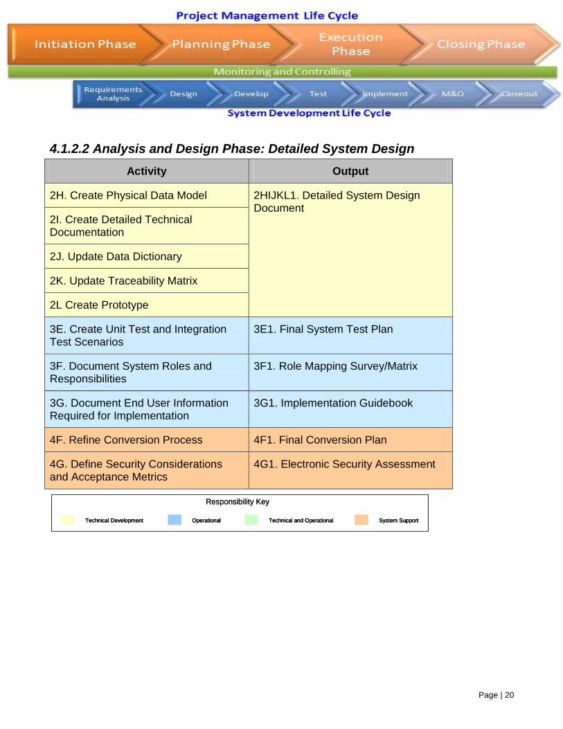
4.1.2.2 Analysis and Design Phase: Detailed System Design
Activity Output
2H. Create Physical Data Model 2HIJKL1. Detailed System Design Document
2I. Create Detailed Technical Documentation
2J. Update Data Dictionary
2K. Update Traceability Matrix
2L Create Prototype
3E. Create Unit Test and Integration Test Scenarios
3E1. Final System Test Plan
3F. Document System Roles and Responsibilities
3F1. Role Mapping Survey/Matrix
3G. Document End User Information Required for Implementation
3G1. Implementation Guidebook
4F. Refine Conversion Process 4F1. Final Conversion Plan
4G. Define Security Considerations and Acceptance Metrics
4G1. Electronic Security Assessment
Technical Development Operational Technical and Operational System Support
Responsibility Key
Technical DevelopmentTechnical Development OperationalOperational Technical and OperationalTechnical and Operational System SupportSystem Support
Responsibility Key
Page | 21
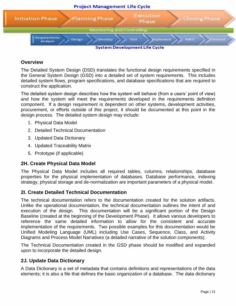
Overview
The Detailed System Design (DSD) translates the functional design requirements specified in the General System Design (GSD) into a detailed set of system requirements. This includes detailed system flows, program specifications, and database specifications that are required to construct the application.
The detailed system design describes how the system will behave (from a users’ point of view) and how the system will meet the requirements developed in the requirements definition component. If a design requirement is dependent on other systems, development activities, procurement, or efforts outside of this project, it should be documented at this point in the design process. The detailed system design may include:
1. Physical Data Model
2. Detailed Technical Documentation
3. Updated Data Dictionary
4. Updated Traceability Matrix
5. Prototype (if applicable)
2H. Create Physical Data Model
The Physical Data Model includes all required tables, columns, relationships, database properties for the physical implementation of databases. Database performance, indexing strategy, physical storage and de-normalization are important parameters of a physical model.
2I. Create Detailed Technical Documentation
The technical documentation refers to the documentation created for the solution artifacts. Unlike the operational documentation, the technical documentation outlines the intent of and execution of the design. This documentation will be a significant portion of the Design Baseline (created at the beginning of the Development Phase). It allows various developers to reference the same detailed information to allow for the consistent and accurate implementation of the requirements. Two possible examples for this documentation would be Unified Modeling Language (UML) including Use Cases, Sequence, Class, and Activity Diagrams and Process Model Narratives (a detailed narrative of the solution components).
The Technical Documentation created in the GSD phase should be modified and expanded upon to incorporate the detailed design.
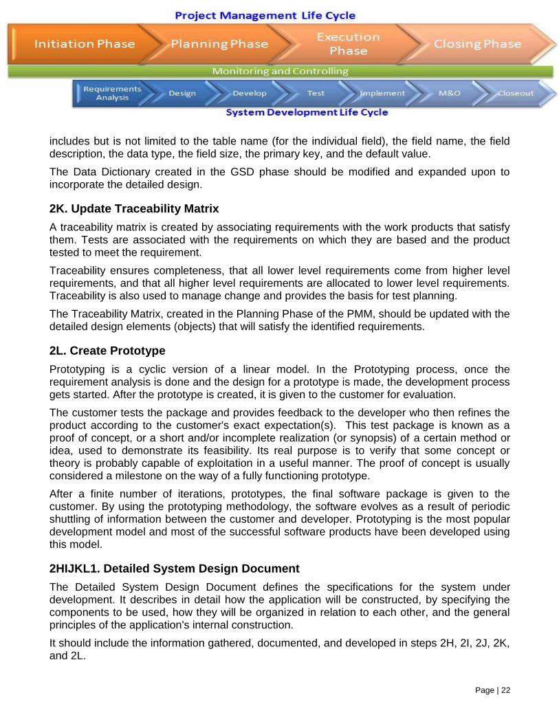
2J. Update Data Dictionary
A Data Dictionary is a set of metadata that contains definitions and representations of the data elements; it is also a file that defines the basic organization of a database. The data dictionary
Page | 22
includes but is not limited to the table name (for the individual field), the field name, the field description, the data type, the field size, the primary key, and the default value.
The Data Dictionary created in the GSD phase should be modified and expanded upon to incorporate the detailed design.
2K. Update Traceability Matrix
A traceability matrix is created by associating requirements with the work products that satisfy them. Tests are associated with the requirements on which they are based and the product tested to meet the requirement.
Traceability ensures completeness, that all lower level requirements come from higher level requirements, and that all higher level requirements are allocated to lower level requirements. Traceability is also used to manage change and provides the basis for test planning.
The Traceability Matrix, created in the Planning Phase of the PMM, should be updated with the detailed design elements (objects) that will satisfy the identified requirements.
2L. Create Prototype
Prototyping is a cyclic version of a linear model. In the Prototyping process, once the requirement analysis is done and the design for a prototype is made, the development process gets started. After the prototype is created, it is given to the customer for evaluation.
The customer tests the package and provides feedback to the developer who then refines the product according to the customer's exact expectation(s). This test package is known as a proof of concept, or a short and/or incomplete realization (or synopsis) of a certain method or idea, used to demonstrate its feasibility. Its real purpose is to verify that some concept or theory is probably capable of exploitation in a useful manner. The proof of concept is usually considered a milestone on the way of a fully functioning prototype.
After a finite number of iterations, prototypes, the final software package is given to the customer. By using the prototyping methodology, the software evolves as a result of periodic shuttling of information between the customer and developer. Prototyping is the most popular development model and most of the successful software products have been developed using this model.
2HIJKL1. Detailed System Design Document
The Detailed System Design Document defines the specifications for the system under development. It describes in detail how the application will be constructed, by specifying the components to be used, how they will be organized in relation to each other, and the general principles of the application's internal construction.
It should include the information gathered, documented, and developed in steps 2H, 2I, 2J, 2K, and 2L.
Page | 23
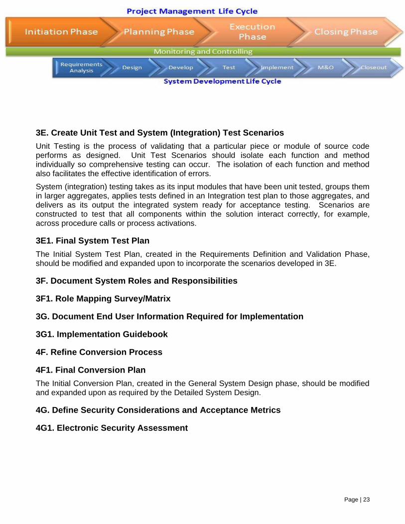
3E. Create Unit Test and System (Integration) Test Scenarios
Unit Testing is the process of validating that a particular piece or module of source code performs as designed. Unit Test Scenarios should isolate each function and method individually so comprehensive testing can occur. The isolation of each function and method also facilitates the effective identification of errors.
System (integration) testing takes as its input modules that have been unit tested, groups them in larger aggregates, applies tests defined in an Integration test plan to those aggregates, and delivers as its output the integrated system ready for acceptance testing. Scenarios are constructed to test that all components within the solution interact correctly, for example, across procedure calls or process activations.
3E1. Final System Test Plan
The Initial System Test Plan, created in the Requirements Definition and Validation Phase, should be modified and expanded upon to incorporate the scenarios developed in 3E.
3F. Document System Roles and Responsibilities
3F1. Role Mapping Survey/Matrix
3G. Document End User Information Required for Implementation
3G1. Implementation Guidebook
4F. Refine Conversion Process
4F1. Final Conversion Plan
The Initial Conversion Plan, created in the General System Design phase, should be modified and expanded upon as required by the Detailed System Design.
4G. Define Security Considerations and Acceptance Metrics
4G1. Electronic Security Assessment
Page | 24
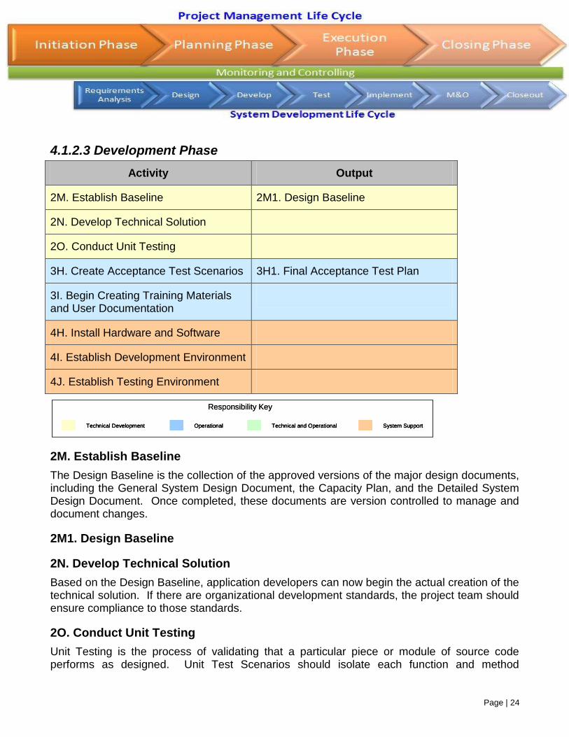
4.1.2.3 Development Phase
Activity Output
2M. Establish Baseline 2M1. Design Baseline
2N. Develop Technical Solution
2O. Conduct Unit Testing
3H. Create Acceptance Test Scenarios 3H1. Final Acceptance Test Plan
3I. Begin Creating Training Materials and User Documentation
4H. Install Hardware and Software
4I. Establish Development Environment
4J. Establish Testing Environment
2M. Establish Baseline
The Design Baseline is the collection of the approved versions of the major design documents, including the General System Design Document, the Capacity Plan, and the Detailed System Design Document. Once completed, these documents are version controlled to manage and document changes.
2M1. Design Baseline
2N. Develop Technical Solution
Based on the Design Baseline, application developers can now begin the actual creation of the technical solution. If there are organizational development standards, the project team should ensure compliance to those standards.
2O. Conduct Unit Testing
Unit Testing is the process of validating that a particular piece or module of source code performs as designed. Unit Test Scenarios should isolate each function and method
Technical Development Operational Technical and Operational System Support
Responsibility Key
Technical DevelopmentTechnical Development OperationalOperational Technical and OperationalTechnical and Operational System SupportSystem Support
Responsibility Key
Page | 25
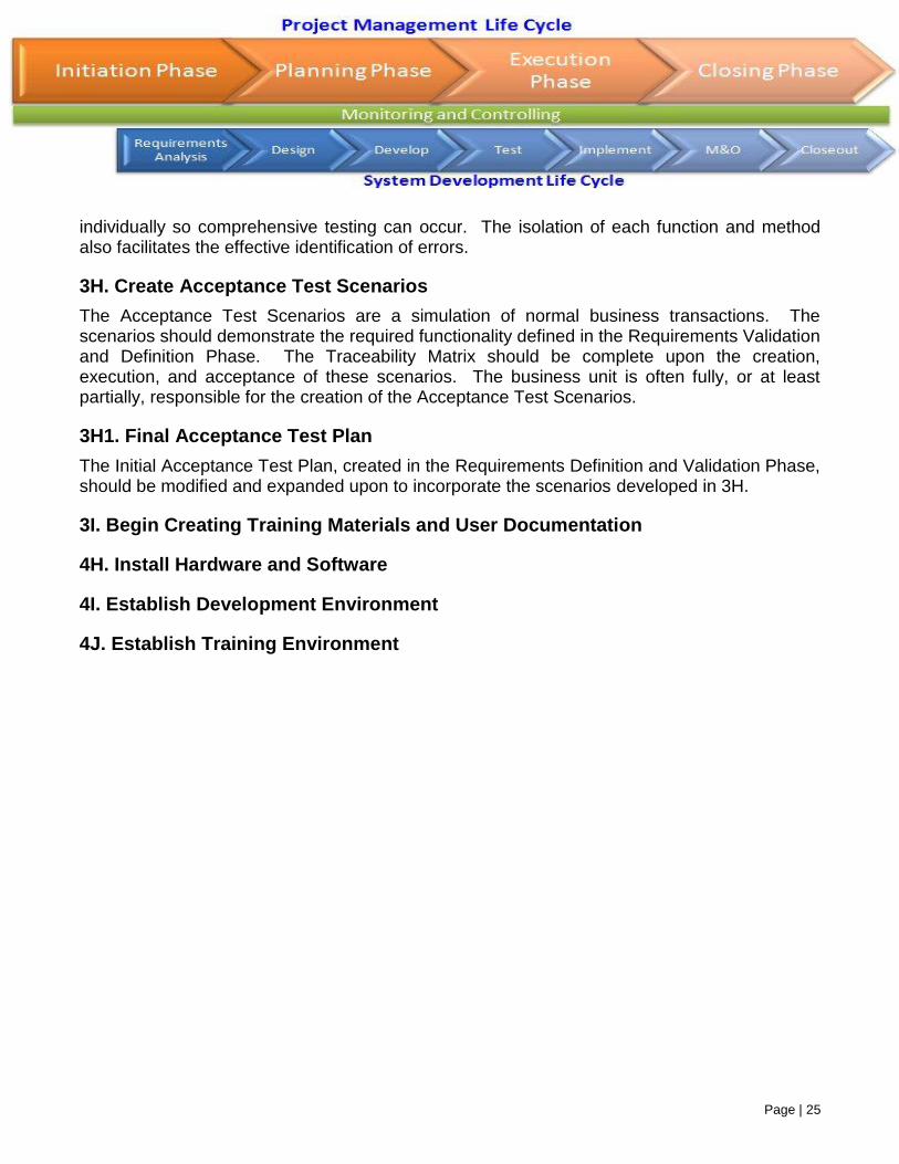
individually so comprehensive testing can occur. The isolation of each function and method also facilitates the effective identification of errors.
3H. Create Acceptance Test Scenarios
The Acceptance Test Scenarios are a simulation of normal business transactions. The scenarios should demonstrate the required functionality defined in the Requirements Validation and Definition Phase. The Traceability Matrix should be complete upon the creation, execution, and acceptance of these scenarios. The business unit is often fully, or at least partially, responsible for the creation of the Acceptance Test Scenarios.
3H1. Final Acceptance Test Plan
The Initial Acceptance Test Plan, created in the Requirements Definition and Validation Phase, should be modified and expanded upon to incorporate the scenarios developed in 3H.
3I. Begin Creating Training Materials and User Documentation
4H. Install Hardware and Software
4I. Establish Development Environment
4J. Establish Training Environment
Page | 26
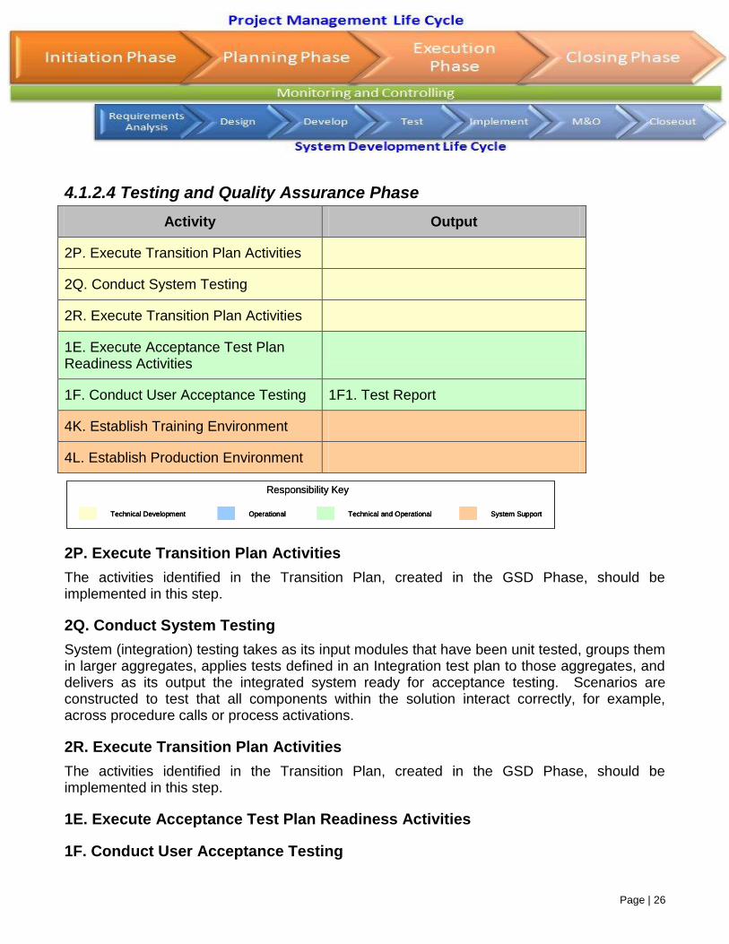
4.1.2.4 Testing and Quality Assurance Phase
Activity Output
2P. Execute Transition Plan Activities
2Q. Conduct System Testing
2R. Execute Transition Plan Activities
1E. Execute Acceptance Test Plan Readiness Activities
1F. Conduct User Acceptance Testing 1F1. Test Report
4K. Establish Training Environment
4L. Establish Production Environment
2P. Execute Transition Plan Activities
The activities identified in the Transition Plan, created in the GSD Phase, should be implemented in this step.
2Q. Conduct System Testing
System (integration) testing takes as its input modules that have been unit tested, groups them in larger aggregates, applies tests defined in an Integration test plan to those aggregates, and delivers as its output the integrated system ready for acceptance testing. Scenarios are constructed to test that all components within the solution interact correctly, for example, across procedure calls or process activations.
2R. Execute Transition Plan Activities
The activities identified in the Transition Plan, created in the GSD Phase, should be implemented in this step.
1E. Execute Acceptance Test Plan Readiness Activities
1F. Conduct User Acceptance Testing
Technical Development Operational Technical and Operational System Support
Responsibility Key
Technical DevelopmentTechnical Development OperationalOperational Technical and OperationalTechnical and Operational System SupportSystem Support
Responsibility Key
Page | 27
1F1. Acceptance Test Certification
The Test Report should be completed for both the System and Acceptance testing. Based on the size, complexity, and scope of the project, it may be recommended that a separate System Test Report and Acceptance Test Report are completed.
4K. Establish Training Environment
4J. Establish Production Environment
Page | 28
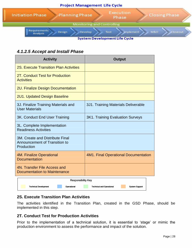
4.1.2.5 Accept and Install Phase
Activity Output
2S. Execute Transition Plan Activities
2T. Conduct Test for Production Activities
2U. Finalize Design Documentation
2U1. Updated Design Baseline
3J. Finalize Training Materials and User Materials
3J1. Training Materials Deliverable
3K. Conduct End User Training 3K1. Training Evaluation Surveys
3L. Complete Implementation Readiness Activities
3M. Create and Distribute Final Announcement of Transition to Production
4M. Finalize Operational Documentation
4M1. Final Operational Documentation
4N. Transfer File Access and Documentation to Maintenance
2S. Execute Transition Plan Activities
The activities identified in the Transition Plan, created in the GSD Phase, should be implemented in this step.
2T. Conduct Test for Production Activities
Prior to the implementation of a technical solution, it is essential to ‘stage’ or mimic the production environment to assess the performance and impact of the solution.
Technical Development Operational Technical and Operational System Support
Responsibility Key
Technical DevelopmentTechnical Development OperationalOperational Technical and OperationalTechnical and Operational System SupportSystem Support
Responsibility Key
Page | 29
2U. Finalize Design Documentation
2U1. Updated Design Baseline
3J. Finalize Training Materials and User Materials
3J1. Training Materials Deliverable
3K. Conduct End User Training
3K1. Training Evaluation Surveys
3L. Complete Implementation Readiness Activities
3M. Create and Distribute Final Announcement of Transition to Production
The Final Announcement of the Transition to Production should be sent to all users and all organizations affected by the implementation. The notice should include:
The schedule of the implementation
Synopsis of the benefits of the new system
Differences between the old and new system, if applicable
Roles and Responsibilities of end user affected by the implementation during this activity
Process to obtain system support, including contact names and phone numbers
4M. Finalize Operational Documentation
4M1. Final Operational Documentation
4N. Transfer File Access and Documentation to Maintenance & Operations