Embed Size (px)
Citation preview

Bulletin J-24
Particulate Monitoring Systems
PMT Particulate Transmitter
PMT Series
INSTALLATION & OPERATING
MANUAL
Dwyer Instruments, Inc. 102 Indiana Highway 212 P.O. Box 373 Michigan City, IN 46361 USA Telephone 800-872-9141 www.dwyer-inst.com

Particulate Monitoring Systems Installation & Operating Manual
Document No. 209-1026-E ii ©2007
I. Technical Support & Return Procedure Dwyer Instruments, Inc. provides industry leading technical support for all product lines. The technical support department is staffed with a team of engineering professionals.
Areas of assistance provided by the Technical Support department include:
• Product Installation
• General Operation
• Application Specific
• Routine Calibration
• EPA Compliance
• Performance Upgrades and Add-On Features
To ensure the best and most efficient technical support please be prepared with the following information prior to contacting Dwyer Instruments, Inc. If it is determined that the component must be returned for evaluation/repair, a Return Material Authorization number will be issued. You must include the RMA number on the packing slip and mark the outside of the shipping container.
• Company Name ________________________________________
• Product Model Number ________________________________________
• Product Serial Number ________________________________________
• Date of Installation ________________________________________
• Reason for Return ________________________________________
Dwyer Instruments Technical Support may be reached by:
Phone: (800) 872-9141
Fax: (219) 872-9057 E-Mail: [email protected]
Hours of Operation: 8AM – 5PM Central Standard Time
• Any control unit or particulate sensor that was exposed to hazardous materials in a process must be properly cleaned in accordance with OSHA standards and a Material Safety Data Sheet (MSDS) completed before it is returned to the factory.
• All shipments returned to the factory must be sent by prepaid transportation.
• All shipments will be returned F.O.B. factory.
• Returns will not be accepted without a Return Material Authorization number.
Particulate Monitoring Systems Installation & Operating Manual
Document No. 209-1026-E iii ©2007
II. Notifications This document contains important information necessary for proper operation of the product. It is strongly urged that all users of the product read this manual in its entirety. All instructions should be followed properly and any questions that arise should be discussed with Dwyer Instruments, Inc.
Any use or distribution of this document without the express consent of Dwyer Instruments, Inc. is strictly prohibited. Any reproduction is prohibited without written permission.
In no event will Dwyer Instruments, Inc. be liable for any mistake, including lost profits, lost savings, environmental compliance costs or other incidental or consequential damages arising out of the use or inability to use this manual, even if advised of the possibility of such damages, or any claim by any other party.
Identifies information about practices or circumstances that can lead to personal injury or death, property damage, or economic loss.
Warning statements help you to:
• Identify a hazard
• Avoid a hazard
• Recognize the consequences
Identifies information that is critical for successful application and
understanding of the product.
Identifies information, sections or statements in this manual that apply to approved hazardous area systems, regulations or installation.
IMPORTANT
Particulate Monitoring Systems Installation & Operating Manual
Document No. 209-1026-E iv ©2007
III. Approvals and Certifications
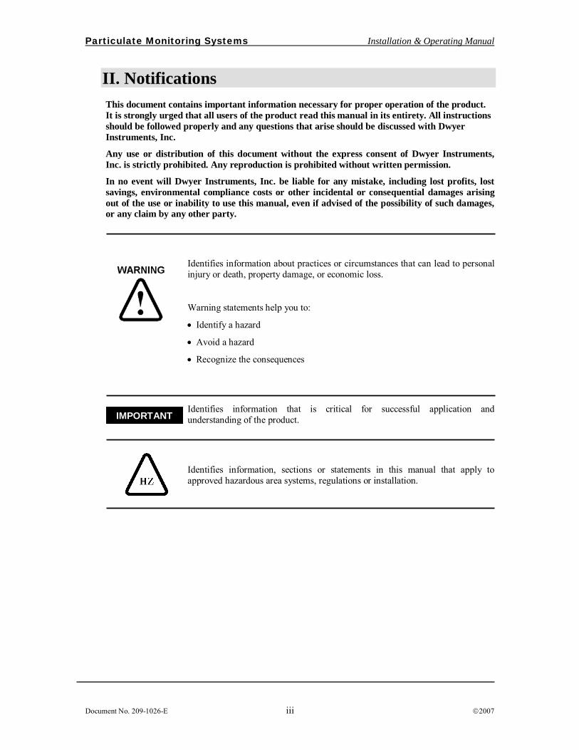
CE Conformant
The Electronics and Particulate Sensors conform to the appropriate country standards and governing regulations listed below:
EN 55011/2002 Limits and methods of measurement of radio interference characteristics of industrial, scientific and medical equipment. Group 1, Class A.
EN61000-6-2/2001 Electromagnetic compatibility – Generic immunity standard Part 6-2: Industrial environments.
EN61000-4-2/2000 Electrostatic discharge (ESD), 4kV contact discharge, 8kV air discharge, 4kV horizontal and vertical coupling planes.
EN61000-4-3/2002 Radiated electromagnetic fields, 10V/m, 80-1000Mhz.
AC line isolation for the Particulate Transmitter must be provided by an external isolating DC power supply with CSA or UL marking. No power supply is provided with or sold as an accessory.
CSA Certified
This Particulate Monitoring system is certified by the Canadian Standards Association (to US and Canadian Standards) for use in hazardous locations as is specified below:
Hazardous Locations
Class I, Division 2 Groups A, B, C, and D
Class II, Division 2 Groups F, G
Class III
Particulate Monitoring Systems Installation & Operating Manual
Document No. 209-1026-E v ©2007
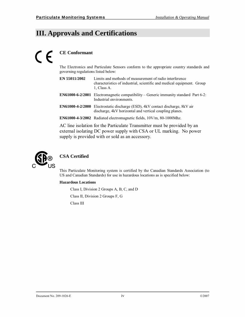
IV. Specifications ELECTRICAL
PARAMETER DETAIL SPECIFICATION NOTE Measurement Units picoamperes (pA) 1 x 10 ⎯ ¹² Amp
Standard 10.0pA – 5000pA Measurement Range Optional 5.0 and 0.5pA – 5000pA
Accuracy ± 5% of Range Full Temp Range Operating -15F to +160F (-25C to +70C) Ambient Temperature
Range Storage -40F to +185F (-40C to +85C)
Digital Filtering Range Ajustable 0.5 Sec – 60 Sec Isolation 500VDC Process to Loop Output Compliance
Max. RLoad = (Vsupply–18V)/0.02A (24VDC = 300Ohm Rload Max.)
Scale Linear or Logarithmic 4-20mA Output
pA Range 0-100, 0-500, 0-1000, 0-5000 Linear 0.5–500, 5–5000 Logarithmic
MECHANICAL Standard ½” NPT Mount Mounting Optional Tri-clamp, Flange
Other, consult factory
Sensor Teflon over Stainless Materials Body Stainless Steel
-40F to +250F (-40C to +120C) -40F to +450F (-40C to +232C) Process Temperature
Range
Operating
-40F to +800F (-40C to +427C) two piece configuration only
Pressure Range Operating Full Vacuum to 10PSI Other, consult factory
Type Painted Cast Aluminum Enclosure Rating NEMA 4X (IP 66)
OPERATING and APPLICATION RANGE 10.0pA 5.0pA Optional
At least 10.0-5000 mg/m³ At least 0.004 to 2.0 gr/cf At least 5.0 – 5000 mg/m³ At least 0.002 to 2.0 gr/cf
Visible Barely Visible To Visible
Particle Concentration (Approximate Guide)
0.5pA Optional
At least 0.5 to 500 mg/m³ At least 0.0002 to 0.2 gr/cf
Barely Visible To Invisible
Particle Velocity 300 ft/min. (91 m/min.) and Higher Particle Size 0.3 Micron and Higher
Particulate Monitoring Systems Installation & Operating Manual
Document No. 209-1026-E vi ©2007
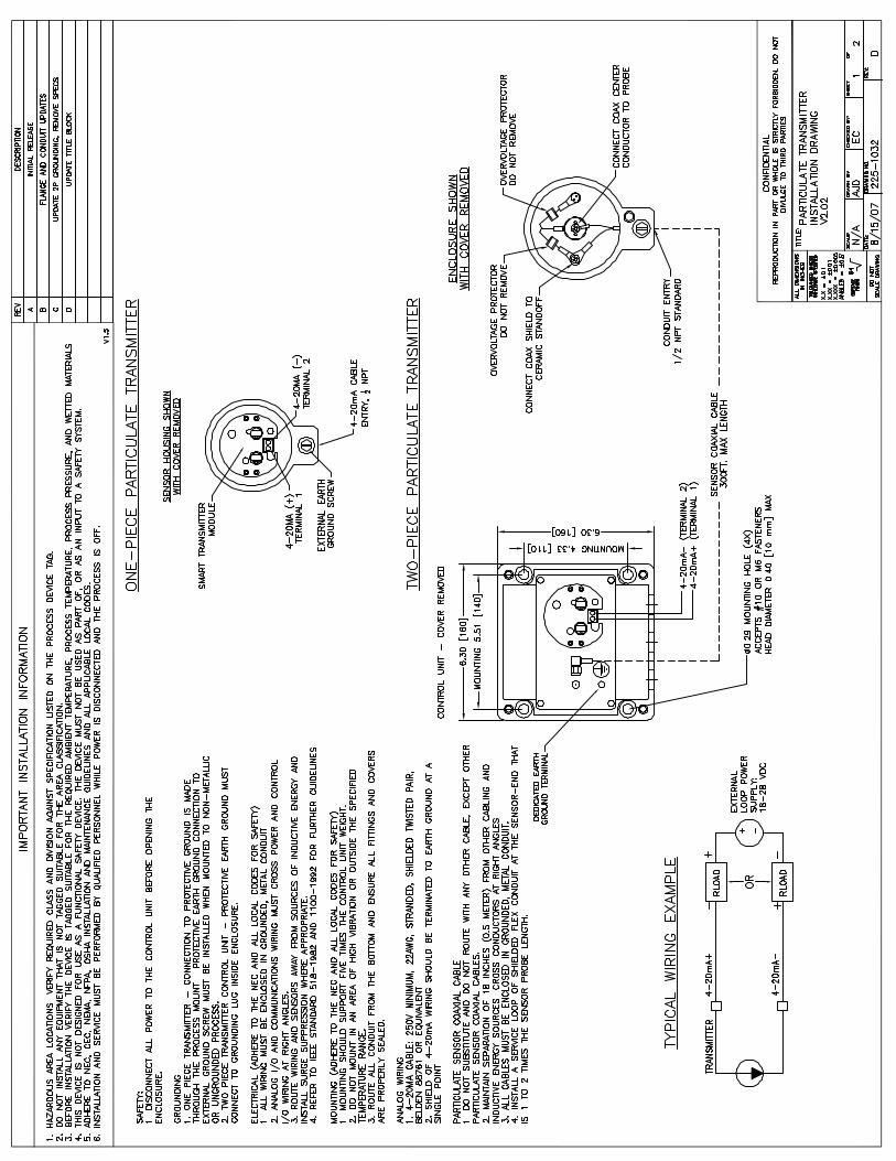
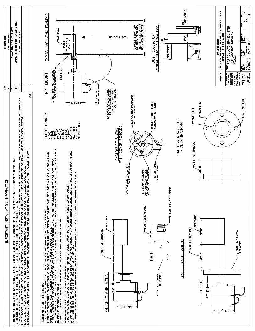
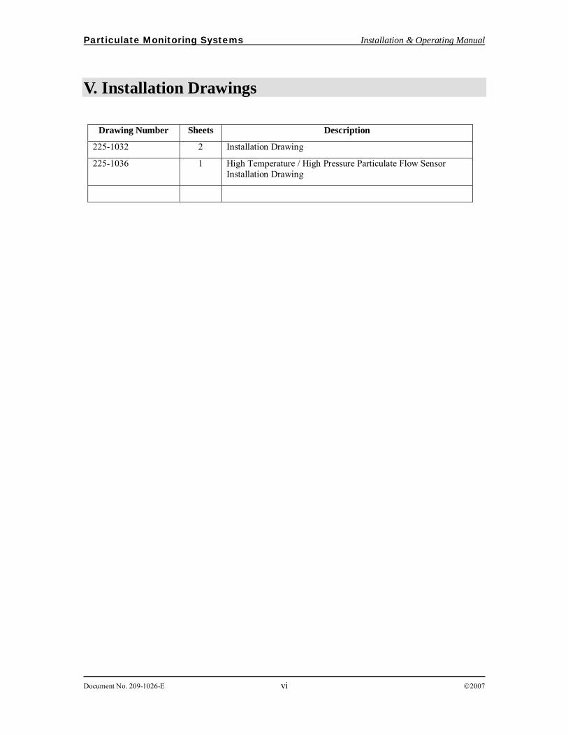
V. Installation Drawings
Drawing Number Sheets Description
225-1032 2 Installation Drawing
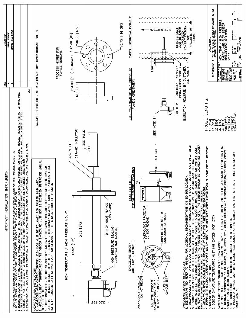
225-1036 1 High Temperature / High Pressure Particulate Flow Sensor Installation Drawing
Particulate Monitoring Systems Installation & Operating Manual
Document No. 210-1015-F Page 1 ©2007
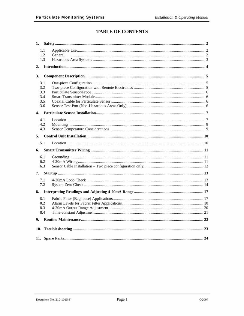
TABLE OF CONTENTS
1. Safety............................................................................................................................................... 2 1.1 Applicable Use.......................................................................................................................... 2 1.2 General ..................................................................................................................................... 2 1.3 Hazardous Area Systems ........................................................................................................... 3
2. Introduction .................................................................................................................................... 4
3. Component Description .................................................................................................................. 5 3.1 One-piece Configuration............................................................................................................ 5 3.2 Two-piece Configuration with Remote Electronics .................................................................... 5 3.3 Particulate Sensor/Probe............................................................................................................ 6 3.4 Smart Transmitter Module......................................................................................................... 6 3.5 Coaxial Cable for Particulate Sensor.......................................................................................... 6 3.6 Sensor Test Port (Non-Hazardous Areas Only) .......................................................................... 6
4. Particulate Sensor Installation........................................................................................................ 7 4.1 Location.................................................................................................................................... 7 4.2 Mounting .................................................................................................................................. 8 4.3 Sensor Temperature Considerations........................................................................................... 9
5. Control Unit Installation............................................................................................................... 10 5.1 Location.................................................................................................................................. 10
6. Smart Transmitter Wiring............................................................................................................ 11 6.1 Grounding............................................................................................................................... 11 6.2 4-20mA Wiring....................................................................................................................... 11 6.3 Sensor Cable Installation – Two piece configuration only......................................................... 12
7. Startup .......................................................................................................................................... 13 7.1 4-20mA Loop Check ............................................................................................................... 13 7.2 System Zero Check ................................................................................................................. 14
8. Interpreting Readings and Adjusting 4-20mA Range.................................................................. 17 8.1 Fabric Filter (Baghouse) Applications...................................................................................... 17 8.2 Alarm Levels for Fabric Filter Applications ............................................................................. 18 8.3 4-20mA Output Range Adjustment.......................................................................................... 20 8.4 Time-constant Adjustment....................................................................................................... 21
9. Routine Maintenance .................................................................................................................... 22
10. Troubleshooting ............................................................................................................................ 23
11. Spare Parts.................................................................................................................................... 24
Particulate Monitoring Systems Installation & Operating Manual
Document No. 210-1015-F Page 2 ©2007
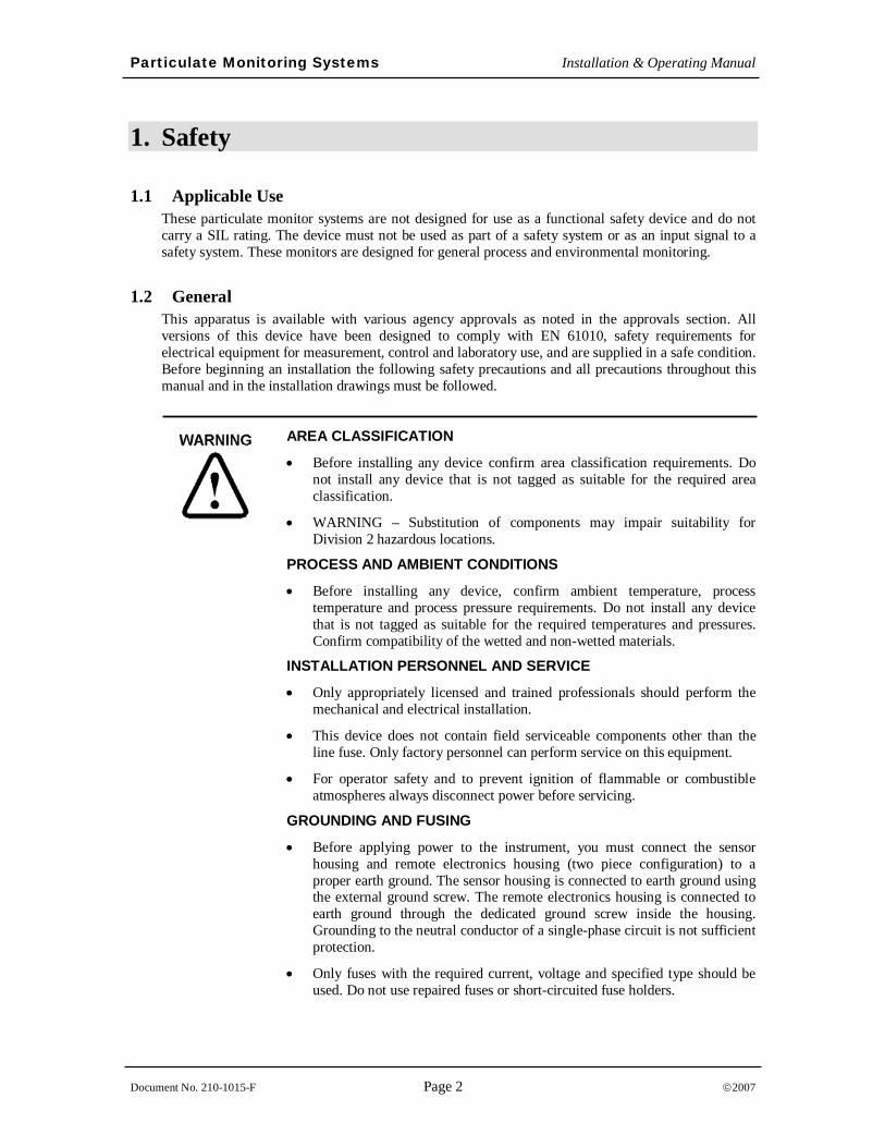
1. Safety
1.1 Applicable Use These particulate monitor systems are not designed for use as a functional safety device and do not carry a SIL rating. The device must not be used as part of a safety system or as an input signal to a safety system. These monitors are designed for general process and environmental monitoring.
1.2 General This apparatus is available with various agency approvals as noted in the approvals section. All versions of this device have been designed to comply with EN 61010, safety requirements for electrical equipment for measurement, control and laboratory use, and are supplied in a safe condition. Before beginning an installation the following safety precautions and all precautions throughout this manual and in the installation drawings must be followed.
AREA CLASSIFICATION
• Before installing any device confirm area classification requirements. Do not install any device that is not tagged as suitable for the required area classification.
• WARNING – Substitution of components may impair suitability for Division 2 hazardous locations.
PROCESS AND AMBIENT CONDITIONS
• Before installing any device, confirm ambient temperature, process temperature and process pressure requirements. Do not install any device that is not tagged as suitable for the required temperatures and pressures. Confirm compatibility of the wetted and non-wetted materials.
INSTALLATION PERSONNEL AND SERVICE
• Only appropriately licensed and trained professionals should perform the mechanical and electrical installation.
• This device does not contain field serviceable components other than the line fuse. Only factory personnel can perform service on this equipment.
• For operator safety and to prevent ignition of flammable or combustible atmospheres always disconnect power before servicing.
GROUNDING AND FUSING
• Before applying power to the instrument, you must connect the sensor housing and remote electronics housing (two piece configuration) to a proper earth ground. The sensor housing is connected to earth ground using the external ground screw. The remote electronics housing is connected to earth ground through the dedicated ground screw inside the housing. Grounding to the neutral conductor of a single-phase circuit is not sufficient protection.
• Only fuses with the required current, voltage and specified type should be used. Do not use repaired fuses or short-circuited fuse holders.
Particulate Monitoring Systems Installation & Operating Manual
Document No. 210-1015-F Page 3 ©2007
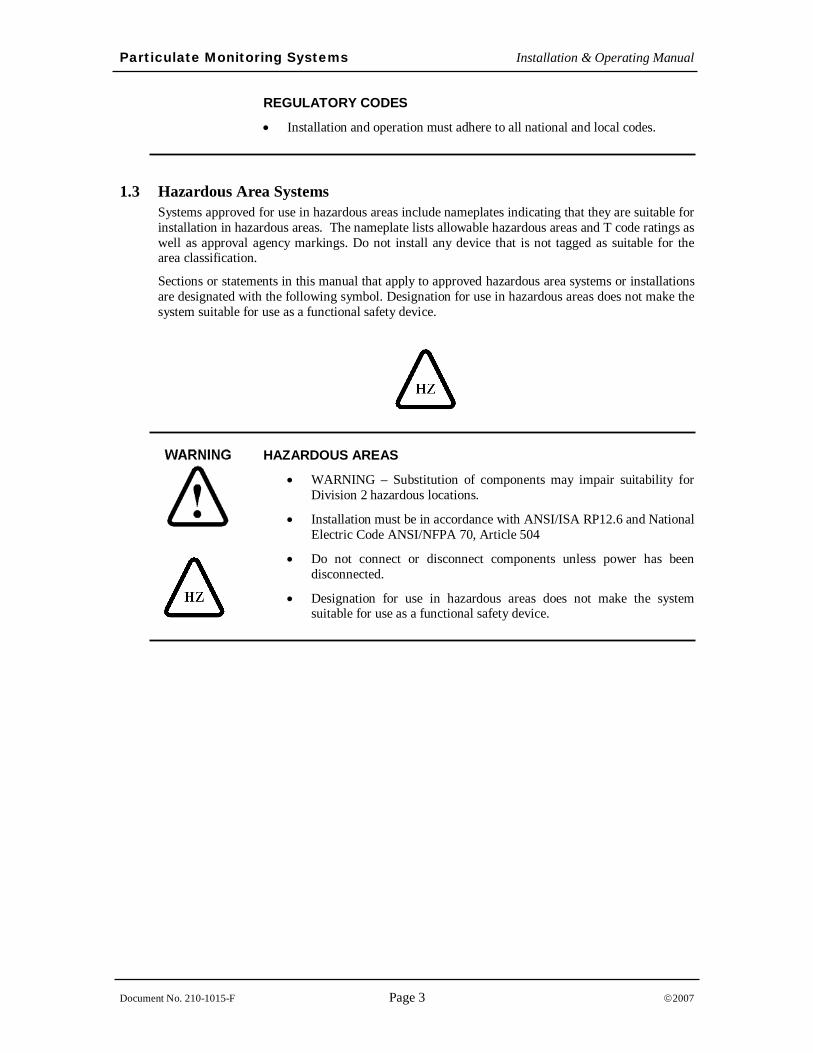
REGULATORY CODES
• Installation and operation must adhere to all national and local codes.
1.3 Hazardous Area Systems Systems approved for use in hazardous areas include nameplates indicating that they are suitable for installation in hazardous areas. The nameplate lists allowable hazardous areas and T code ratings as well as approval agency markings. Do not install any device that is not tagged as suitable for the area classification.
Sections or statements in this manual that apply to approved hazardous area systems or installations are designated with the following symbol. Designation for use in hazardous areas does not make the system suitable for use as a functional safety device.
HAZARDOUS AREAS
• WARNING – Substitution of components may impair suitability for Division 2 hazardous locations.
• Installation must be in accordance with ANSI/ISA RP12.6 and National Electric Code ANSI/NFPA 70, Article 504
• Do not connect or disconnect components unless power has been disconnected.
• Designation for use in hazardous areas does not make the system suitable for use as a functional safety device.
Particulate Monitoring Systems Installation & Operating Manual
Document No. 210-1015-F Page 4 ©2007
2. Introduction A Particulate Monitoring System consists of a control unit, a particulate sensor and a sensor coaxial cable. Applications include continuous emissions monitoring, baghouse filter leak detection and process particulate flow monitoring. Types of particulate include both solid particulates (dusts, powders, granulars, and pellets) and liquid particulates (mists). Various control unit models and sensors are provided to match the application and process monitoring needs.
Principle of Operation Particulate Monitoring Systems employ a highly reliable technology based on induction. A sensor probe is mounted in an airflow stream such as a pipe, duct or stack (for small tubing an inline non-intrusive ring sensor is employed). As particulate flows near and over the sensing element, minute electrical currents are induced in the sensor and transferred to the control unit by a coaxial cable. A microprocessor filters and processes the signal into a normalized, absolute output that is linear to the mass concentration of particulate.
_ MASS CORRELATION
It is important to note that the above relation between instrument units (pA) and actual mass (mg/m3 or gr/cf) is just an approximate guide for selecting the appropriate model and range and for providing a general indication of the typical particulate levels monitored. For a true correlation between (pA) and actual mass (mg/m3 or gr/cf), a gravimetric correlation such as an isokinetic sample must be performed for each application and a recommended model and detection level must be ordered. It is also important to note that the accuracy of such correlations is application dependent and produces the best results with consistent particulate and process conditions. The user must follow proper procedures and must understand the typical accuracy of such correlation techniques. Consult factory for details.
IMPORTANT
Particulate Monitoring Systems Installation & Operating Manual
Document No. 210-1015-F Page 5 ©2007
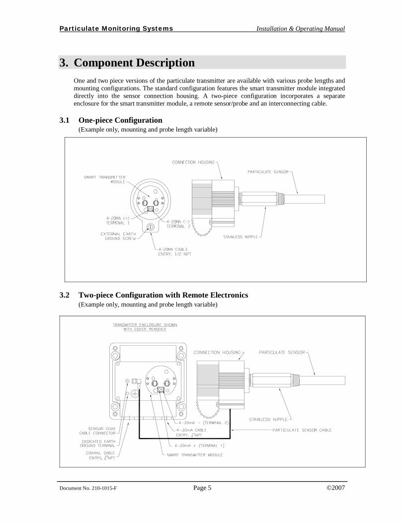
3. Component Description One and two piece versions of the particulate transmitter are available with various probe lengths and mounting configurations. The standard configuration features the smart transmitter module integrated directly into the sensor connection housing. A two-piece configuration incorporates a separate enclosure for the smart transmitter module, a remote sensor/probe and an interconnecting cable.
3.1 One-piece Configuration (Example only, mounting and probe length variable)
3.2 Two-piece Configuration with Remote Electronics (Example only, mounting and probe length variable)
Particulate Monitoring Systems Installation & Operating Manual
Document No. 210-1015-F Page 6 ©2007
3.3 Particulate Sensor/Probe The particulate sensor consists of a stainless probe with a non-conductive protective layer or coating, a stainless steel nipple/mount and the sensor housing. It is a very rugged assembly that is virtually maintenance-free. It does not require special alignment, is not affected by normal vibration and does not require cleaning.
3.4 Smart Transmitter Module The smart transmitter module processes the signals induced into the probe, quantifying and digitally filtering them into an absolute measurement of pA (picoamps). The pA reading is transmitted over a 4-20mA current loop for remote monitoring with a control system, PLC, panel meter, recorder etc. It is important that the 4-20mA signal be converted back into pA at the monitoring location to enable evaluating the instrument output readings properly. Electrical isolation is provided between the 4-20mA loop and the pA measurement circuitry. This isolation provides immunity to ground loop and power supply/plc analog input card grounding possibilities.
The smart transmitter module is located directly inside the particulate sensor housing for one-piece configurations. For two-piece configurations the smart transmitter module is located in a separate TYPE 4X enclosure.
3.5 Coaxial Cable for Particulate Sensor The cable that connects the particulate sensor to the control unit is a high-quality coaxial cable specifically designed for the system. Maximum length is 300 ft (91m). Do not use substitute cable.
This cable is required for two-piece configurations only.
3.6 Sensor Test Port (Non-Hazardous Areas Only) The test port is not a necessary component to operate the system, but it is recommended. It is a 1/8”NPT x 3” pipe nipple used to introduce particulate into the process to perform a natural response check. The nipple is screwed into or welded to the pipe/duct upstream of the sensor. Particles are injected into the flow stream to simulate a natural increase in particle flow. It is primarily intended for use at negative pressure locations in fabric filter outlet ducting so that when the cap is removed line suction will enable particles to be sucked into the flow. A test port is not recommended for hazardous area applications. Location: A test port should be installed in a negative pressure location. It must be located upstream of the sensor so particulate can flow very near and around the sensor. It should be located at least 3 ft (1 m) upstream of the sensor and it should be located on the same side of the duct as the sensor so particles can pass very near and around the sensor. If possible locate the test port at ground level.
Mounting: The test port is either screwed into a 1/8 inch NPT threaded hole, or welded in position. (Note: A foot or so of tubing can be connected to the nipple to make it easy to draw particles out of a container. Only a pinch of particulate at a time is needed for a response check.)
_ TEST PORT INSTALLATION
• Installation of a sensor test port enables checking the response to an actual increase in particulate.
IMPORTANT
Particulate Monitoring Systems Installation & Operating Manual
Document No. 210-1015-F Page 7 ©2007
4. Particulate Sensor Installation The following applies for both one and two piece configurations.
4.1 Location The following factors should be considered when determining the sensor location:
Area Classification
Flow conditions
Ambient & Process Temperatures
Process Pressure
Electrical (Faraday) shielding
Atmospheric shielding (in the case of ducts and stacks open to atmosphere)
Access for installation and service
INSTALLATION PERSONNEL
• Only appropriately licensed professionals should install this product.
• For operator safety and to prevent ignition of flammable or combustible atmospheres always disconnect power before servicing.
• WARNING – Substitution of components may impair suitability for Division 2 hazardous locations.
SENSOR LOCATION
• Before installing the sensor, confirm area classification requirements. Do not install any device that is not tagged suitable for the required area classification. The sensor may be installed in the following areas:
o Class I, Division 2, Groups A, B, C, D
o Class II, Division 2, Groups F, G
o Class III
o Any ordinary location
• Before installing the sensor, confirm ambient temperature requirements. Do not install any device that is not tagged as suitable for the required temperatures or pressures. Confirm compatibility of wetted and non-wetted materials.
• For hazardous areas, a maximum ambient temperature of the particulate sensor enclosure must not be exceeded. Refer to the Temperature Considerations section for full details.
Particulate Monitoring Systems Installation & Operating Manual
Document No. 210-1015-F Page 8 ©2007
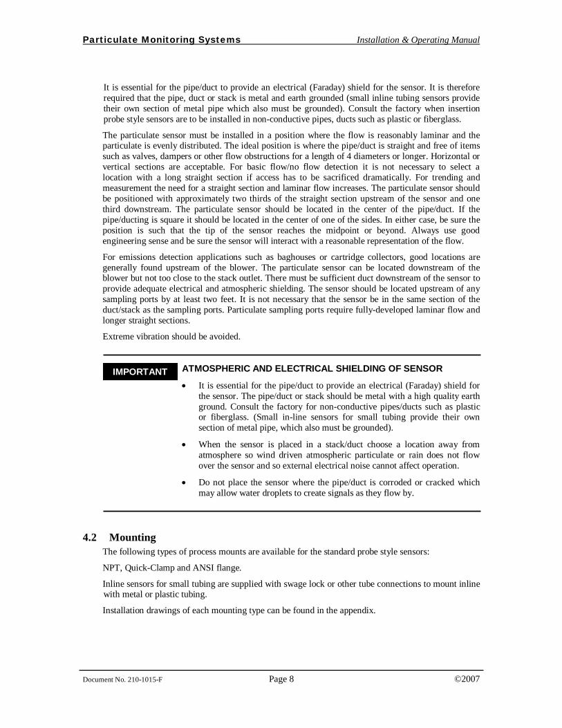
It is essential for the pipe/duct to provide an electrical (Faraday) shield for the sensor. It is therefore required that the pipe, duct or stack is metal and earth grounded (small inline tubing sensors provide their own section of metal pipe which also must be grounded). Consult the factory when insertion probe style sensors are to be installed in non-conductive pipes, ducts such as plastic or fiberglass.
The particulate sensor must be installed in a position where the flow is reasonably laminar and the particulate is evenly distributed. The ideal position is where the pipe/duct is straight and free of items such as valves, dampers or other flow obstructions for a length of 4 diameters or longer. Horizontal or vertical sections are acceptable. For basic flow/no flow detection it is not necessary to select a location with a long straight section if access has to be sacrificed dramatically. For trending and measurement the need for a straight section and laminar flow increases. The particulate sensor should be positioned with approximately two thirds of the straight section upstream of the sensor and one third downstream. The particulate sensor should be located in the center of the pipe/duct. If the pipe/ducting is square it should be located in the center of one of the sides. In either case, be sure the position is such that the tip of the sensor reaches the midpoint or beyond. Always use good engineering sense and be sure the sensor will interact with a reasonable representation of the flow.
For emissions detection applications such as baghouses or cartridge collectors, good locations are generally found upstream of the blower. The particulate sensor can be located downstream of the blower but not too close to the stack outlet. There must be sufficient duct downstream of the sensor to provide adequate electrical and atmospheric shielding. The sensor should be located upstream of any sampling ports by at least two feet. It is not necessary that the sensor be in the same section of the duct/stack as the sampling ports. Particulate sampling ports require fully-developed laminar flow and longer straight sections.
Extreme vibration should be avoided.
_ ATMOSPHERIC AND ELECTRICAL SHIELDING OF SENSOR
• It is essential for the pipe/duct to provide an electrical (Faraday) shield for the sensor. The pipe/duct or stack should be metal with a high quality earth ground. Consult the factory for non-conductive pipes/ducts such as plastic or fiberglass. (Small in-line sensors for small tubing provide their own section of metal pipe, which also must be grounded).
• When the sensor is placed in a stack/duct choose a location away from atmosphere so wind driven atmospheric particulate or rain does not flow over the sensor and so external electrical noise cannot affect operation.
• Do not place the sensor where the pipe/duct is corroded or cracked which may allow water droplets to create signals as they flow by.
4.2 Mounting The following types of process mounts are available for the standard probe style sensors:
NPT, Quick-Clamp and ANSI flange.
Inline sensors for small tubing are supplied with swage lock or other tube connections to mount inline with metal or plastic tubing.
Installation drawings of each mounting type can be found in the appendix.
IMPORTANT
Particulate Monitoring Systems Installation & Operating Manual
Document No. 210-1015-F Page 9 ©2007
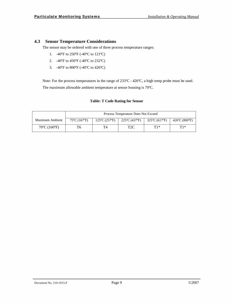
4.3 Sensor Temperature Considerations The sensor may be ordered with one of three process temperature ranges:
1. -40ºF to 250ºF (-40ºC to 121ºC)
2. -40ºF to 450ºF (-40ºC to 232ºC)
3. -40ºF to 800ºF (-40ºC to 426ºC)
Note: For the process temperatures in the range of 233ºC - 426ºC, a high temp probe must be used.
The maximum allowable ambient temperature at sensor housing is 70ºC.
Table: T Code Rating for Sensor
Process Temperature Does Not Exceed
Maximum Ambient 75ºC (167ºF) 125ºC (257ºF) 225ºC (437ºF) 325ºC (617ºF) 426ºC (800ºF)
70ºC (160ºF) T6 T4 T2C T1* T1*
Particulate Monitoring Systems Installation & Operating Manual
Document No. 210-1015-F Page 10 ©2007
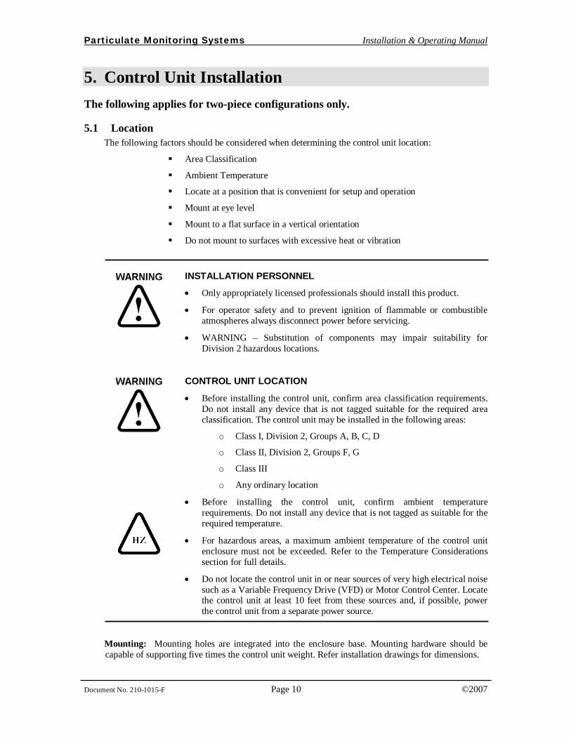
5. Control Unit Installation
The following applies for two-piece configurations only.
5.1 Location The following factors should be considered when determining the control unit location:
Area Classification
Ambient Temperature
Locate at a position that is convenient for setup and operation
Mount at eye level
Mount to a flat surface in a vertical orientation
Do not mount to surfaces with excessive heat or vibration
INSTALLATION PERSONNEL
• Only appropriately licensed professionals should install this product.
• For operator safety and to prevent ignition of flammable or combustible atmospheres always disconnect power before servicing.
• WARNING – Substitution of components may impair suitability for Division 2 hazardous locations.
CONTROL UNIT LOCATION
• Before installing the control unit, confirm area classification requirements. Do not install any device that is not tagged suitable for the required area classification. The control unit may be installed in the following areas:
o Class I, Division 2, Groups A, B, C, D
o Class II, Division 2, Groups F, G
o Class III
o Any ordinary location
• Before installing the control unit, confirm ambient temperature requirements. Do not install any device that is not tagged as suitable for the required temperature.
• For hazardous areas, a maximum ambient temperature of the control unit enclosure must not be exceeded. Refer to the Temperature Considerations section for full details.
• Do not locate the control unit in or near sources of very high electrical noise such as a Variable Frequency Drive (VFD) or Motor Control Center. Locate the control unit at least 10 feet from these sources and, if possible, power the control unit from a separate power source.
Mounting: Mounting holes are integrated into the enclosure base. Mounting hardware should be capable of supporting five times the control unit weight. Refer installation drawings for dimensions.
Particulate Monitoring Systems Installation & Operating Manual
Document No. 210-1015-F Page 11 ©2007
6. Smart Transmitter Wiring
6.1 Grounding Proper grounding is essential to ensure reliable operation and operator safety.
CONTROL UNIT GROUNDING For One-Piece configurations:
• Connection to protective ground is made through the process mount. Protective earth ground connection to external ground screw must be installed when mounted to non-metallic or ungrounded process.
For Two-Piece configurations:
• Connection to protective ground is made through the process mount. Protective earth ground connection to external ground screw must be installed when mounted to non-metallic or ungrounded process.
• The remote electronics housing is connected to a separate earth ground through an internal ground screw. Grounding to the neutral conductor of a single phase circuit is not sufficient protection.
6.2 4-20mA Wiring An appropriately licensed electrician must perform all electrical connections.
CONTROL UNIT WIRING
• All wiring must be rated 250V minimum. Analog 4-20mA wire should be 22 AWG stranded shielded twisted pair, Belden 88761 or equivalent.
• Analog 4-20mA cable shield should be terminated to earth ground in the PLC/ DCS/ panel meter cabinet. The shielded wire should be terminated to ground at one end only, never at both ends.
• The coaxial cable must be in conduit that is separate from all other circuits for two piece configurations.
Conduit openings are provided in the bottom of the enclosure to route wiring into the enclosure. Never drill new conduit openings in the side or top of the enclosure as a bad conduit seal may allow water to enter the enclosure.
Particulate Monitoring Systems Installation & Operating Manual
Document No. 210-1015-F Page 12 ©2007
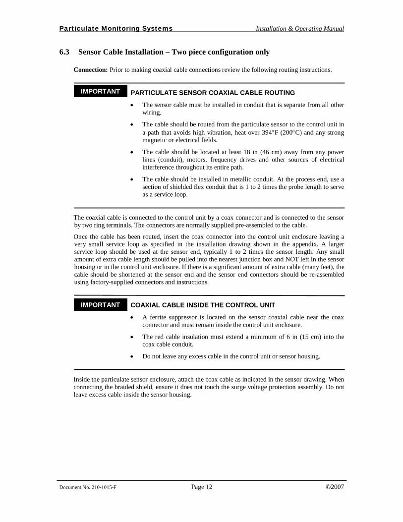
6.3 Sensor Cable Installation – Two piece configuration only
Connection: Prior to making coaxial cable connections review the following routing instructions.
_ PARTICULATE SENSOR COAXIAL CABLE ROUTING
• The sensor cable must be installed in conduit that is separate from all other wiring.
• The cable should be routed from the particulate sensor to the control unit in a path that avoids high vibration, heat over 394°F (200°C) and any strong magnetic or electrical fields.
• The cable should be located at least 18 in (46 cm) away from any power lines (conduit), motors, frequency drives and other sources of electrical interference throughout its entire path.
• The cable should be installed in metallic conduit. At the process end, use a section of shielded flex conduit that is 1 to 2 times the probe length to serve as a service loop.
The coaxial cable is connected to the control unit by a coax connector and is connected to the sensor by two ring terminals. The connectors are normally supplied pre-assembled to the cable.
Once the cable has been routed, insert the coax connector into the control unit enclosure leaving a very small service loop as specified in the installation drawing shown in the appendix. A larger service loop should be used at the sensor end, typically 1 to 2 times the sensor length. Any small amount of extra cable length should be pulled into the nearest junction box and NOT left in the sensor housing or in the control unit enclosure. If there is a significant amount of extra cable (many feet), the cable should be shortened at the sensor end and the sensor end connectors should be re-assembled using factory-supplied connectors and instructions.
_ COAXIAL CABLE INSIDE THE CONTROL UNIT
• A ferrite suppressor is located on the sensor coaxial cable near the coax connector and must remain inside the control unit enclosure.
• The red cable insulation must extend a minimum of 6 in (15 cm) into the coax cable conduit.
• Do not leave any excess cable in the control unit or sensor housing.
Inside the particulate sensor enclosure, attach the coax cable as indicated in the sensor drawing. When connecting the braided shield, ensure it does not touch the surge voltage protection assembly. Do not leave excess cable inside the sensor housing.
IMPORTANT
IMPORTANT
Particulate Monitoring Systems Installation & Operating Manual
Document No. 210-1015-F Page 13 ©2007
7. Startup
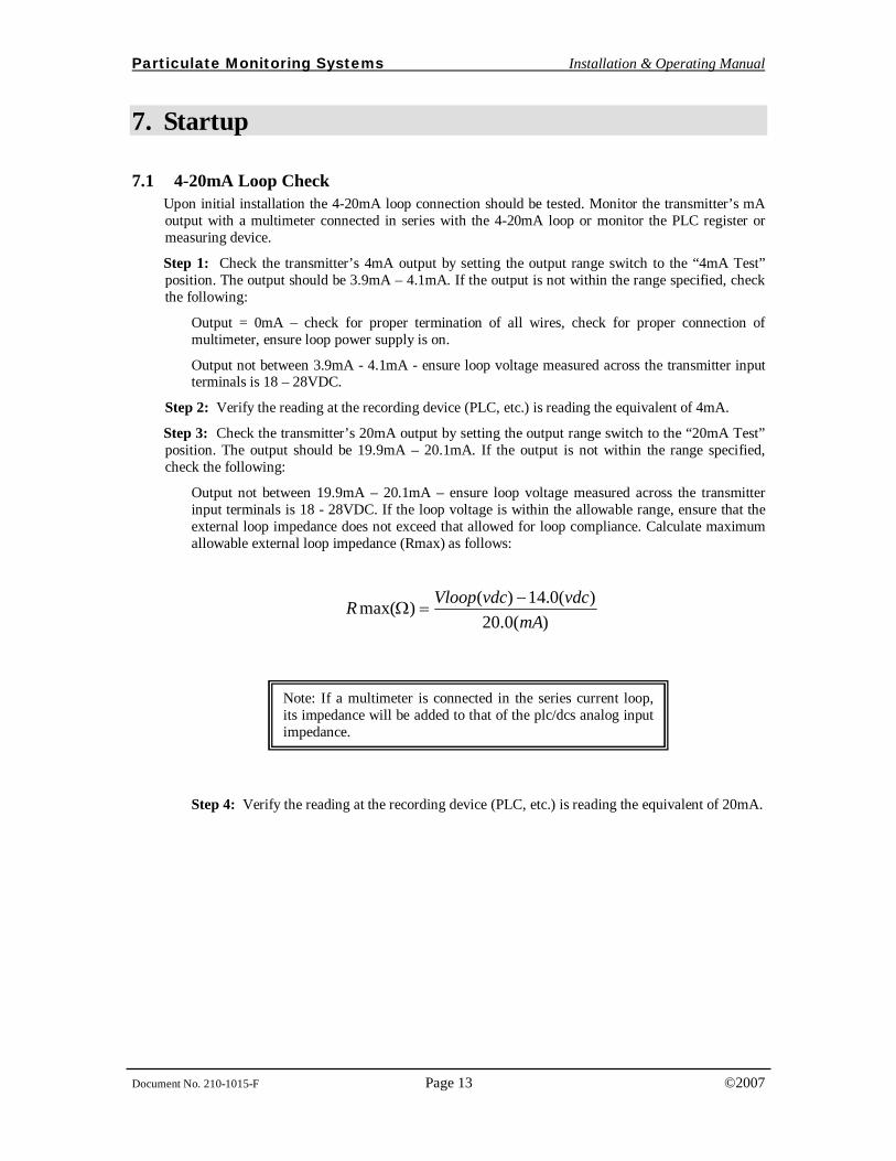
7.1 4-20mA Loop Check Upon initial installation the 4-20mA loop connection should be tested. Monitor the transmitter’s mA output with a multimeter connected in series with the 4-20mA loop or monitor the PLC register or measuring device.
Step 1: Check the transmitter’s 4mA output by setting the output range switch to the “4mA Test” position. The output should be 3.9mA – 4.1mA. If the output is not within the range specified, check the following:
Output = 0mA – check for proper termination of all wires, check for proper connection of multimeter, ensure loop power supply is on.
Output not between 3.9mA - 4.1mA - ensure loop voltage measured across the transmitter input terminals is 18 – 28VDC.
Step 2: Verify the reading at the recording device (PLC, etc.) is reading the equivalent of 4mA.
Step 3: Check the transmitter’s 20mA output by setting the output range switch to the “20mA Test” position. The output should be 19.9mA – 20.1mA. If the output is not within the range specified, check the following:
Output not between 19.9mA – 20.1mA – ensure loop voltage measured across the transmitter input terminals is 18 - 28VDC. If the loop voltage is within the allowable range, ensure that the external loop impedance does not exceed that allowed for loop compliance. Calculate maximum allowable external loop impedance (Rmax) as follows:
)(0.20
)(0.14)()max(mA
vdcvdcVloopR −=Ω
Step 4: Verify the reading at the recording device (PLC, etc.) is reading the equivalent of 20mA.
Note: If a multimeter is connected in the series current loop, its impedance will be added to that of the plc/dcs analog input impedance.
Particulate Monitoring Systems Installation & Operating Manual
Document No. 210-1015-F Page 14 ©2007
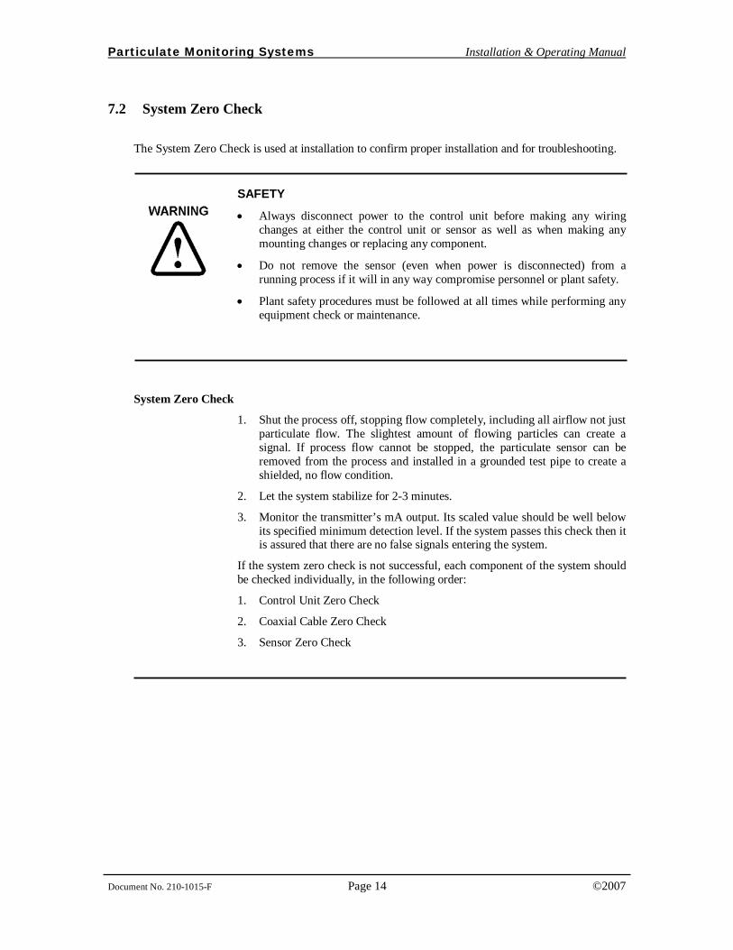
7.2 System Zero Check
The System Zero Check is used at installation to confirm proper installation and for troubleshooting.
SAFETY
• Always disconnect power to the control unit before making any wiring changes at either the control unit or sensor as well as when making any mounting changes or replacing any component.
• Do not remove the sensor (even when power is disconnected) from a running process if it will in any way compromise personnel or plant safety.
• Plant safety procedures must be followed at all times while performing any equipment check or maintenance.
System Zero Check
1. Shut the process off, stopping flow completely, including all airflow not just particulate flow. The slightest amount of flowing particles can create a signal. If process flow cannot be stopped, the particulate sensor can be removed from the process and installed in a grounded test pipe to create a shielded, no flow condition.
2. Let the system stabilize for 2-3 minutes.
3. Monitor the transmitter’s mA output. Its scaled value should be well below its specified minimum detection level. If the system passes this check then it is assured that there are no false signals entering the system.
If the system zero check is not successful, each component of the system should be checked individually, in the following order:
1. Control Unit Zero Check
2. Coaxial Cable Zero Check
3. Sensor Zero Check
Particulate Monitoring Systems Installation & Operating Manual
Document No. 210-1015-F Page 15 ©2007
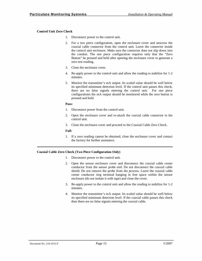
Control Unit Zero Check
1. Disconnect power to the control unit.
2. For a two piece configuration, open the enclosure cover and unscrew the coaxial cable connector from the control unit. Leave the connector inside the control unit enclosure. Make sure the connector does not slip down into the conduit. The one piece configuration requires only that the “Zero Button” be pressed and held after opening the enclosure cover to generate a zero test reading.
3. Close the enclosure cover.
4. Re-apply power to the control unit and allow the reading to stabilize for 1-2 minutes.
5. Monitor the transmitter’s mA output. Its scaled value should be well below its specified minimum detection level. If the control unit passes this check, there are no false signals entering the control unit. For one piece configurations the mA output should be monitored while the zero button is pressed and held.
Pass:
1. Disconnect power from the control unit.
2. Open the enclosure cover and re-attach the coaxial cable connector to the control unit.
3. Close the enclosure cover and proceed to the Coaxial Cable Zero Check.
Fail:
1. If a zero reading cannot be obtained, close the enclosure cover and contact the factory for further assistance.
Coaxial Cable Zero Check (Two Piece Configuration Only)
1. Disconnect power to the control unit.
2. Open the sensor enclosure cover and disconnect the coaxial cable center conductor from the sensor probe end. Do not disconnect the coaxial cable shield. Do not remove the probe from the process. Leave the coaxial cable center conductor ring terminal hanging in free space within the sensor enclosure (do not isolate it with tape) and close the cover.
3. Re-apply power to the control unit and allow the reading to stabilize for 1-2 minutes.
4. Monitor the transmitter’s mA output. Its scaled value should be well below its specified minimum detection level. If the coaxial cable passes this check then there are no false signals entering the coaxial cable.
Particulate Monitoring Systems Installation & Operating Manual
Document No. 210-1015-F Page 16 ©2007
Pass:
1. Disconnect power to the control unit.
2. Open the sensor enclosure cover and re-attach the coaxial cable center conductor to the sensor probe end.
3. Close the sensor enclosure cover and proceed to the sensor zero check.
Fail:
1. Check cable installation and routing instructions in the Installation section of this manual for proper cable installation. Make any changes necessary.
2. Contact the factory for further assistance.
Once the control unit and coaxial cable zero have been checked, proceed to the Sensor Zero Check. To perform the sensor zero check the process flow must be stopped or a sensor test pipe (available from Factory) or length of metal pipe will be needed (4”-6” diameter pipe or larger). The pipe should be at least 3 in (8 cm) longer than the probe itself and must be grounded. The length of pipe will serve as an electrical shield for the probe while it is out of the process.
Sensor Zero Check
1. Do not remove the sensor from a running process if it will in any way compromise personnel or plant safety procedures.
2. Disconnect power to the control unit.
3. Remove the sensor from the process and insert it into the grounded metal test pipe.
4. Re-apply power to the control unit and allow the reading to stabilize for 1-2 minutes.
5. Monitor the transmitter’s mA output. Its scaled value should be well below its specified minimum detection level. If the sensor passes this check there are no false signals from the sensor.
Pass:
1. Disconnect power to the control unit.
2. Remove the sensor from the grounded test pipe and re-insert into the process.
Fail:
1. Contact the factory for further assistance.
When performing a zero check, keep in mind that it may be acceptable to consider a small false signal negligible. For example if the baseline readings are 100pA and a system zero offset of 1pA was found, this is only a 1% affect on the normal readings. If using the device for basic flow/no flow detection or basic emissions detection, this would not be significant.
Particulate Monitoring Systems Installation & Operating Manual
Document No. 210-1015-F Page 17 ©2007
8. Interpreting Readings and Adjusting 4-20mA Range
8.1 Fabric Filter (Baghouse) Applications
Particulate flow is very dynamic in nature, thus the output signal is also usually very dynamic. This is more often the case with fabric filter and dust collection exhaust monitoring applications where filter emissions and filter cleaning systems can cause wide ranging variations in the particulate levels. When monitoring downstream of fabric filter, it is often possible for the difference between baseline readings and peak readings following cleaning cycles, to vary by a factor of 10 or even 100. This is the reason for the logarithmic output (linear output is also easily selected).
The logarithmic scale provides the ability to simultaneously monitor and resolve the baseline and peak readings. It is not uncommon to have baseline readings of less than 10pA while at the same time peak readings may be over a hundred or more.
Particulate levels listed below are typical for new or well maintained bag or cartridge filter dust collection system. Many factors, other than generic bag wear may contribute to high particulate levels including but not limited to: Improper filter installation, bad tube sheet seals, improper filter media for process conditions, high differential pressure or a lack of a filter cake buildup.
PARTICULATE READING GUIDE FOR FABRIC FILTERS
• The guide below is only an approximate guide for modern, highly-efficient baghouses
• With larger or older baghouses, readings can be significantly higher than the ranges shown below
• Shaker and reverse air baghouses will have higher peak readings as compared to pulse jet
• Readings tend to be higher when new filters are installed and a filter cake has yet to form
• With small cartridge filters, the readings tend to be at the lower end of the ranges
• Readings tend to also be lower with highly-efficient filter media such as Gore-Tex® fabric (Gore-Tex is a registered trademark of W.L. Gore & Associates.)
Typical Readings and Guide for New Efficient Fabric Filters
AVERAGE BASELINE READINGS
PEAK READINGS (after cleaning cycle) FILTER CONDITION
1 – 10 pA Less than 50pA No significant emissions 10 – 100 pA Less than 500pA Onset of emissions
100 – 1000pA Greater than 500pA Significant emissions present
IMPORTANT
Particulate Monitoring Systems Installation & Operating Manual
Document No. 210-1015-F Page 18 ©2007
8.2 Alarm Levels for Fabric Filter Applications
In fabric filter applications it is common to use alarms for indicating sustained high readings. Internal alarms are not included in 4-20mA loop powered transmitter products. Alarming for loop powered transmitter products is typically a part of an external system such as a PLC or Plant Wide Control System.
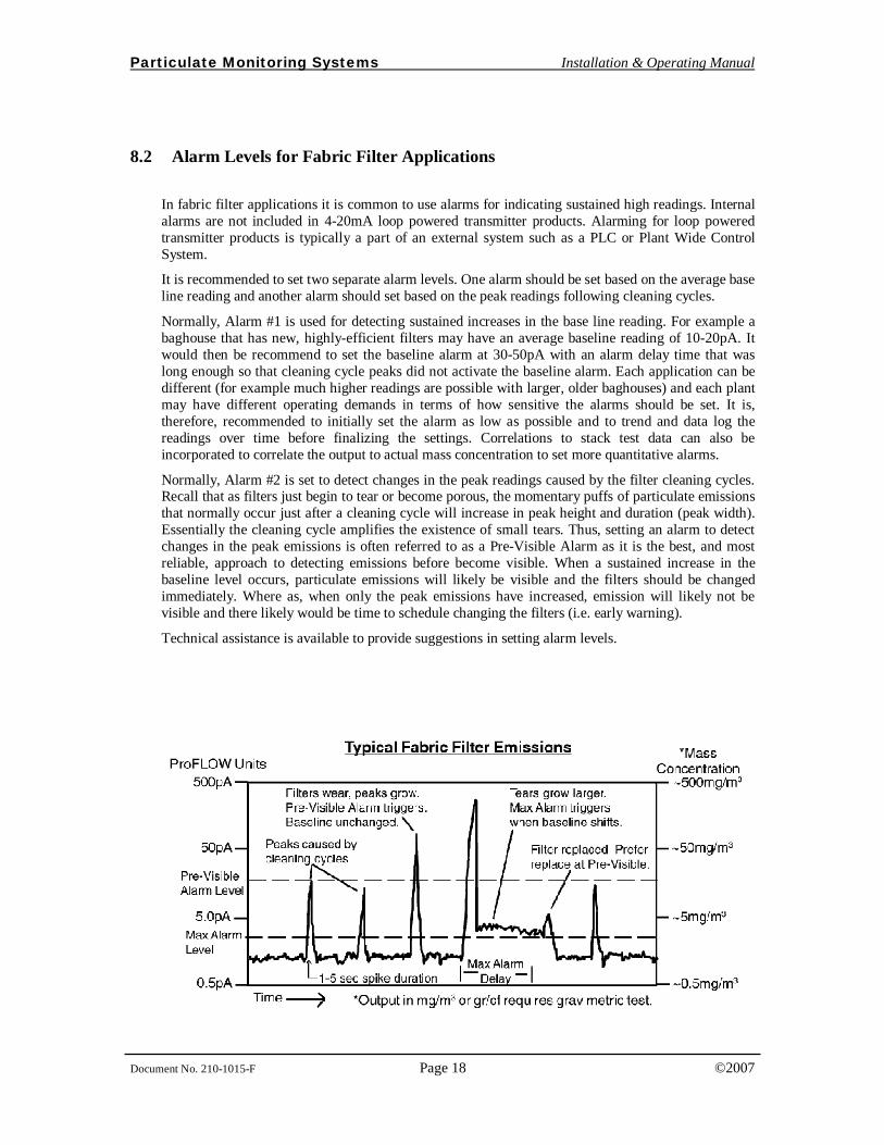
It is recommended to set two separate alarm levels. One alarm should be set based on the average base line reading and another alarm should set based on the peak readings following cleaning cycles.
Normally, Alarm #1 is used for detecting sustained increases in the base line reading. For example a baghouse that has new, highly-efficient filters may have an average baseline reading of 10-20pA. It would then be recommend to set the baseline alarm at 30-50pA with an alarm delay time that was long enough so that cleaning cycle peaks did not activate the baseline alarm. Each application can be different (for example much higher readings are possible with larger, older baghouses) and each plant may have different operating demands in terms of how sensitive the alarms should be set. It is, therefore, recommended to initially set the alarm as low as possible and to trend and data log the readings over time before finalizing the settings. Correlations to stack test data can also be incorporated to correlate the output to actual mass concentration to set more quantitative alarms.
Normally, Alarm #2 is set to detect changes in the peak readings caused by the filter cleaning cycles. Recall that as filters just begin to tear or become porous, the momentary puffs of particulate emissions that normally occur just after a cleaning cycle will increase in peak height and duration (peak width). Essentially the cleaning cycle amplifies the existence of small tears. Thus, setting an alarm to detect changes in the peak emissions is often referred to as a Pre-Visible Alarm as it is the best, and most reliable, approach to detecting emissions before become visible. When a sustained increase in the baseline level occurs, particulate emissions will likely be visible and the filters should be changed immediately. Where as, when only the peak emissions have increased, emission will likely not be visible and there likely would be time to schedule changing the filters (i.e. early warning).
Technical assistance is available to provide suggestions in setting alarm levels.
Particulate Monitoring Systems Installation & Operating Manual
Document No. 210-1015-F Page 19 ©2007
_ ALARM LEVELS FOR EPA COMPLIANT LEAK DETECTION
• Alarm levels for EPA compliant leak detection such as MACT regulations should initially be set as low as possible until sufficient trend data has been logged and all considerations have been made.
• Do not increase the alarm levels without proper justification.
• Documentation of properly determined alarm levels is recommended as well as locking out alarm set point adjustment except to authorized personnel.
• Consult factory for alarm set point assistance and EPA Compliance Software for advanced alarming and alarm record keeping.
IMPORTANT
Particulate Monitoring Systems Installation & Operating Manual
Document No. 210-1015-F Page 20 ©2007
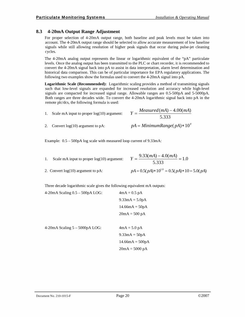
8.3 4-20mA Output Range Adjustment For proper selection of 4-20mA output range, both baseline and peak levels must be taken into account. The 4-20mA output range should be selected to allow accurate measurement of low baseline signals while still allowing resolution of higher peak signals that occur during pulse-jet cleaning cycles.
The 4-20mA analog output represents the linear or logarithmic equivalent of the “pA” particulate levels. Once the analog output has been transmitted to the PLC or chart recorder, it is recommended to convert the 4-20mA signal back into pA to assist in data interpretation, alarm level determination and historical data comparison. This can be of particular importance for EPA regulatory applications. The following two examples show the formulas used to convert the 4-20mA signal into pA.
Logarithmic Scale (Recommended): Logarithmic scaling provides a method of transmitting signals such that low-level signals are expanded for increased resolution and accuracy while high-level signals are compacted for increased signal range. Allowable ranges are 0.5-500pA and 5-5000pA. Both ranges are three decades wide. To convert the 4-20mA logarithmic signal back into pA in the remote plc/dcs, the following formula is used:
1. Scale mA input to proper log(10) argument: 333.5
)(00.4)( mAmAMeasuredY −=
2. Convert log(10) argument to pA: YpAgeMinimumRanpA 10)( ∗=
Example: 0.5 – 500pA log scale with measured loop current of 9.33mA:
1. Scale mA input to proper log(10) argument: 0.1333.5
)(0.4)(33.9=
−=
mAmAY
2. Convert log(10) argument to pA: )(0.510)(5.010)(5.0 0.1 pApApApA =∗=∗=
Three decade logarithmic scale gives the following equivalent mA outputs:
4-20mA Scaling 0.5 – 500pA LOG: 4mA = 0.5 pA
9.33mA = 5.0pA
14.66mA = 50pA
20mA = 500 pA
4-20mA Scaling 5 – 5000pA LOG: 4mA = 5.0 pA
9.33mA = 50pA
14.66mA = 500pA
20mA = 5000 pA
Particulate Monitoring Systems Installation & Operating Manual
Document No. 210-1015-F Page 21 ©2007
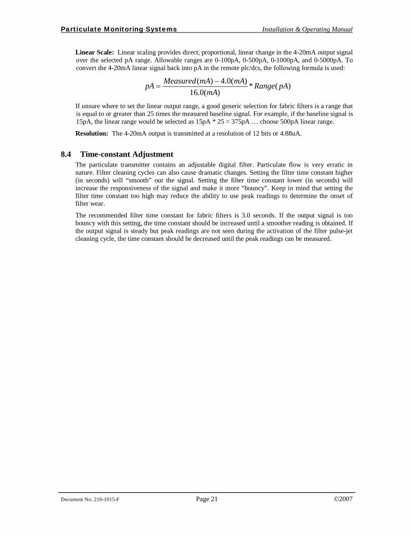
Linear Scale: Linear scaling provides direct, proportional, linear change in the 4-20mA output signal over the selected pA range. Allowable ranges are 0-100pA, 0-500pA, 0-1000pA, and 0-5000pA. To convert the 4-20mA linear signal back into pA in the remote plc/dcs, the following formula is used:
)(*)(0.16
)(0.4)( pARangemA
mAmAMeasuredpA −=
If unsure where to set the linear output range, a good generic selection for fabric filters is a range that is equal to or greater than 25 times the measured baseline signal. For example, if the baseline signal is 15pA, the linear range would be selected as 15pA * 25 = 375pA … choose 500pA linear range.
Resolution: The 4-20mA output is transmitted at a resolution of 12 bits or 4.88uA.
8.4 Time-constant Adjustment The particulate transmitter contains an adjustable digital filter. Particulate flow is very erratic in nature. Filter cleaning cycles can also cause dramatic changes. Setting the filter time constant higher (in seconds) will “smooth” out the signal. Setting the filter time constant lower (in seconds) will increase the responsiveness of the signal and make it more “bouncy”. Keep in mind that setting the filter time constant too high may reduce the ability to use peak readings to determine the onset of filter wear.
The recommended filter time constant for fabric filters is 3.0 seconds. If the output signal is too bouncy with this setting, the time constant should be increased until a smoother reading is obtained. If the output signal is steady but peak readings are not seen during the activation of the filter pulse-jet cleaning cycle, the time constant should be decreased until the peak readings can be measured.
Particulate Monitoring Systems Installation & Operating Manual
Document No. 210-1015-F Page 22 ©2007
9. Routine Maintenance
EQUIPMENT MAINTENANCE
• Only appropriately licensed professionals should perform maintenance on this product.
• WARNING – To prevent ignition of flammable or combustible atmospheres and for operator safety, always disconnect power before servicing.
Particulate Sensor: The sensor does not normally need any cleaning and for optimal performance, routine cleaning of the sensor is not recommended.
Transmitter Module: The transmitter module is zeroed at the factory and normally does not require adjustment. Zero adjustment can be checked once every 6-12 months.
Particulate Monitoring Systems Installation & Operating Manual
Document No. 210-1015-F Page 23 ©2007
10. Troubleshooting The most important aspects of troubleshooting are to keep in mind the instrument is monitoring small signals. The quality of cable connectors should not be overlooked. The sensor housing should be kept dry and clean. Break all troubleshooting down into the basic system components, the sensor, smart transmitter module and 4-20mA loop.
False High Signals (False Alarms)
1. When an apparent false high signal is present, first check the process to be sure the particulate level has not increased. Keep in mind that the system can detect very low levels. In filtration applications the system can detect invisible particulate levels and very small emissions.
2. Check the sensor cover and conduit seal to be sure they were not left open allowing rain to enter the housing. Check the coaxial cable (two piece configuration only) connectors using a digital voltmeter and check for shorts. If nothing can be found, conduct a system zero check.
No Reading or Alarm (When Believed Necessary)
1. Increase the particulate level or introduce particulate into the air stream and monitor for a response. If the system responds properly re-evaluate the selected alarm points and the process conditions.
2. If there is no response, check for electrical continuity from the sensor to the control unit end of the coax cable (two piece configuration only).
3. Contact the factory for a Field Test Unit that can generate a signal to check response and calibration (two-piece configuration only).
Particulate Monitoring Systems Installation & Operating Manual
Document No. 210-1015-F Page 24 ©2007
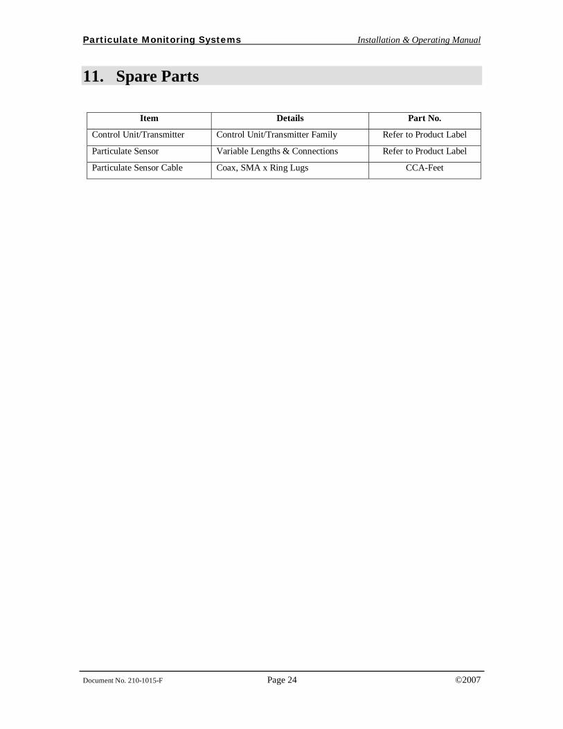
11. Spare Parts
Item Details Part No.
Control Unit/Transmitter Control Unit/Transmitter Family Refer to Product Label
Particulate Sensor Variable Lengths & Connections Refer to Product Label
Particulate Sensor Cable Coax, SMA x Ring Lugs CCA-Feet

Particulate Monitoring Systems Installation & Operating Manual
Document No. 210-1015-F Page 25 ©2007
Notes: