Embed Size (px)
Citation preview
12 Clintonville RoadNorthford, CT 06472-1610 USA203-484-7161 • FAX 203-484-7118www.notifier.com
High-Speed Network Communications Module Product Installation Document
PN 54014:B2 04/25/2014 14-0370
1 Product OverviewThe High-Speed Network Communications Module (HS-NCM) provides a means for connecting specific Notifier fire alarm control products to High-Speed NOTI•FIRE•NET™. There are six types of HS-NCMs available: HS-NCM-W for connecting nodes with twisted-pair wire; HS-NCM-MF and HS-NCM-SF are used for connecting nodes with fiber-optic cable; HS-NCM-WMF and HS-NCM-WSF are used for connecting nodes with fiber-optic cables to nodes with twisted-pair wire; HS-NCM-MFSF for connecting nodes with multi-mode fiber cable to nodes with single-mode fiber cable. The following equipment may be used with the HS-NCM:
* - Power for the HS-NCM for use with UL 9th Edition panels is provided via the NUP connection on the FACP itself or an external UL/ULC listed power supply.** - Power for the HS-NCM for use with UL 8th Edition panels must be provided by a 24 VDC UL/ULC listed power supply.
The following revisions† of the UL 9th edition panels require a 24 VDC UL/ULC listed power source to power the HS-
NCM and can not be powered via the panel’s NUP port‡:
† The revision and assembly name can be found on the fire panel’s circuit board.
‡ NUP Port connections are still required for communication between the HS-NCM and the fire panel.
One HS-NCM can provide network communication for up to two nodes (including fire alarm control panels and network annunciators).
Per UL 864 9th Edition, the HS-NCM uses Active Multiplex Type 3 Communication.
The HS-NCM can also be configured as a high-speed repeater for applications requiring distances beyond the specified limits between two nodes. For configuration and setup information, refer to “HS-NCM Configuration” on page 5. For limitations and network wiring information for the HS-NCM, refer to the High-Speed Noti•Fire•Net Manual.
For instructions on the additional capabilities available with the DVC-EM, refer to the DVC and DAA Series Installation Manual.
• Input power requirements: 24 VDC, 0.400 A, regulated, power-limited compatible power supply UL/ULC listed for fire protective signalling use.
• Communications circuit requirements: Refer to the High-Speed Noti•Fire•Net Manual for segment length limitations.
UL 9th Edition* UL 8th Edition**• NFS2-3030 • NFS-3030• NFS2-640 • NFS-640• NFS-320 • NCA• NCA-2• DVC-EM• ONYXWorks
NFS-320 CPU2-640PCB Revision E or older NFS2-640 CPU2-640PCB Revision E or olderNFS2-3030 CPU2-3030PCC Revision I or olderDVC-EM DVC-EMPCB Revision F or olderDVC DVC-PCA -All RevisionsNCA-2 NCA-2PCC Revision I or older
NOTE: All wiring connections are supervised and power limited.
2
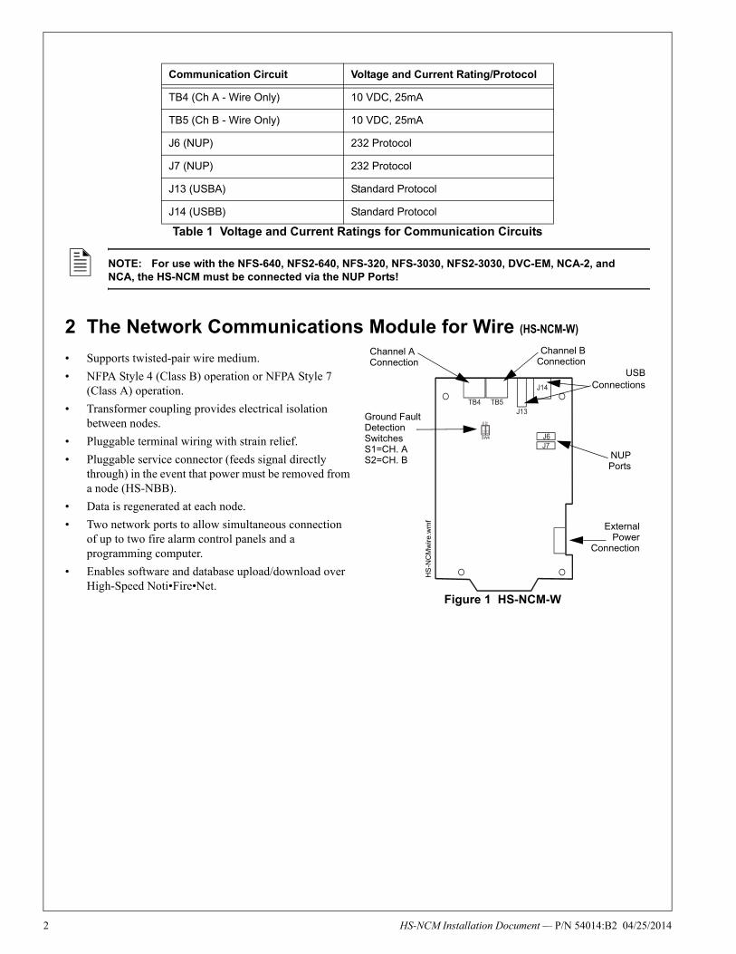
2 The Network Communications Module for Wire (HS-NCM-W)
• Supports twisted-pair wire medium.
• NFPA Style 4 (Class B) operation or NFPA Style 7 (Class A) operation.
• Transformer coupling provides electrical isolation between nodes.
• Pluggable terminal wiring with strain relief.
• Pluggable service connector (feeds signal directly through) in the event that power must be removed from a node (HS-NBB).
• Data is regenerated at each node.
• Two network ports to allow simultaneous connection of up to two fire alarm control panels and a programming computer.
• Enables software and database upload/download over High-Speed Noti•Fire•Net.
Communication Circuit Voltage and Current Rating/Protocol
TB4 (Ch A - Wire Only) 10 VDC, 25mA
TB5 (Ch B - Wire Only) 10 VDC, 25mA
J6 (NUP) 232 Protocol
J7 (NUP) 232 Protocol
J13 (USBA) Standard Protocol
J14 (USBB) Standard Protocol
Table 1 Voltage and Current Ratings for Communication Circuits
NOTE: For use with the NFS-640, NFS2-640, NFS-320, NFS-3030, NFS2-3030, DVC-EM, NCA-2, and NCA, the HS-NCM must be connected via the NUP Ports!
Ground Fault Detection SwitchesS1=CH. AS2=CH. B
Figure 1 HS-NCM-W
HS
-NC
Mw
ire.w
mf
NUPPorts
Channel BConnection
Channel A Connection
USBConnections
ExternalPower
Connection
HS-NCM Installation Document — P/N 54014:B2 04/25/2014
HS
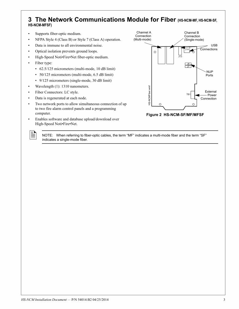
3 The Network Communications Module for Fiber (HS-NCM-MF, HS-NCM-SF, HS-NCM-MFSF)
• Supports fiber-optic medium.
• NFPA Style 4 (Class B) or Style 7 (Class A) operation.
• Data is immune to all environmental noise.
• Optical isolation prevents ground loops.
• High-Speed Noti•Fire•Net fiber-optic medium.
• Fiber type:
• 62.5/125 micrometers (multi-mode, 10 dB limit)
• 50/125 micrometers (multi-mode, 6.5 dB limit)
• 9/125 micrometers (single-mode, 30 dB limit)
• Wavelength (1): 1310 nanometers.
• Fiber Connectors: LC style.
• Data is regenerated at each node.
• Two network ports to allow simultaneous connection of up to two fire alarm control panels and a programming computer.
• Enables software and database upload/download over High-Speed Noti•Fire•Net.
NOTE: When referring to fiber-optic cables, the term “MF” indicates a multi-mode fiber and the term “SF” indicates a single-mode fiber.
HS
-NC
MF
ibe
r.w
mf
Figure 2 HS-NCM-SF/MF/MFSF
NUPPorts
Channel B Connection (Single-mode)
Channel AConnection
(Multi-mode)
USBConnections
ExternalPower
Connection
-NCM Installation Document — P/N 54014:B2 04/25/2014 3
4
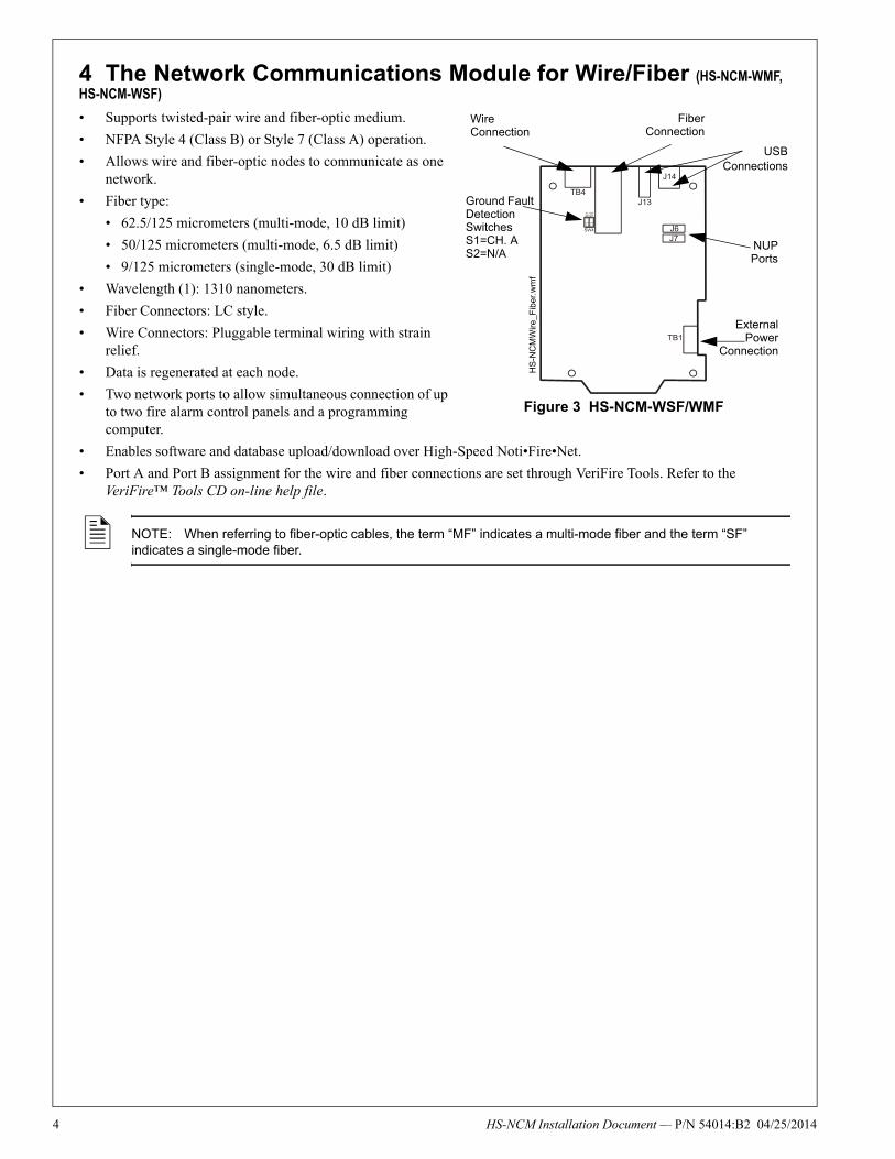
4 The Network Communications Module for Wire/Fiber (HS-NCM-WMF, HS-NCM-WSF)
• Supports twisted-pair wire and fiber-optic medium.
• NFPA Style 4 (Class B) or Style 7 (Class A) operation.
• Allows wire and fiber-optic nodes to communicate as one network.
• Fiber type:
• 62.5/125 micrometers (multi-mode, 10 dB limit)
• 50/125 micrometers (multi-mode, 6.5 dB limit)
• 9/125 micrometers (single-mode, 30 dB limit)
• Wavelength (1): 1310 nanometers.
• Fiber Connectors: LC style.
• Wire Connectors: Pluggable terminal wiring with strain relief.
• Data is regenerated at each node.
• Two network ports to allow simultaneous connection of up to two fire alarm control panels and a programming computer.
• Enables software and database upload/download over High-Speed Noti•Fire•Net.
• Port A and Port B assignment for the wire and fiber connections are set through VeriFire Tools. Refer to the VeriFire™ Tools CD on-line help file.
NOTE: When referring to fiber-optic cables, the term “MF” indicates a multi-mode fiber and the term “SF” indicates a single-mode fiber.
Figure 3 HS-NCM-WSF/WMF
HS
-NC
MW
ire_F
ibe
r.w
mf
Ground Fault Detection SwitchesS1=CH. AS2=N/A
FiberConnection
Wire Connection
USBConnections
NUPPorts
ExternalPower
Connection
HS-NCM Installation Document — P/N 54014:B2 04/25/2014
HS
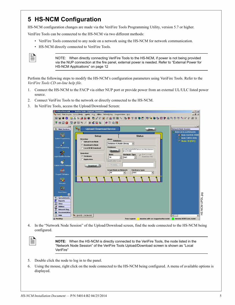
5 HS-NCM ConfigurationHS-NCM configuration changes are made via the VeriFire Tools Programming Utility, version 5.7 or higher.
VeriFire Tools can be connected to the HS-NCM via two different methods:
• VeriFire Tools connected to any node on a network using the HS-NCM for network communication.
• HS-NCM directly connected to VeriFire Tools.
Perform the following steps to modify the HS-NCM’s configuration parameters using VeriFire Tools. Refer to the VeriFire Tools CD on-line help file.
1. Connect the HS-NCM to the FACP via either NUP port or provide power from an external UL/ULC listed power source.
2. Connect VeriFire Tools to the network or directly connected to the HS-NCM.
3. In VeriFire Tools, access the Upload/Download Screen:
4. In the “Network Node Session” of the Upload/Download screen, find the node connected to the HS-NCM being configured.
5. Double click the node to log in to the panel.
6. Using the mouse, right click on the node connected to the HS-NCM being configured. A menu of available options is displayed.
NOTE: When directly connecting VeriFire Tools to the HS-NCM, if power is not being provided via the NUP connection at the fire panel, external power is needed. Refer to “External Power for HS-NCM Applications” on page 12
NOTE: When the HS-NCM is directly connected to the VeriFire Tools, the node listed in the “Network Node Session” of the VeriFire Tools Upload/Download screen is shown as “Local VeriFire”
HS
NC
M U
PD
L.jp
g
-NCM Installation Document — P/N 54014:B2 04/25/2014 5
6
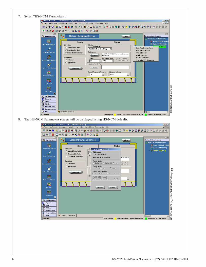
7. Select “HS-NCM Parameters”.
8. The HS-NCM Parameters screen will be displayed listing HS-NCM defaults.
HS
NC
M c
on
text
me
nu.jp
gH
S N
CM
UP
DL.
jpg
, HS
NC
MP
AR
MS
FO
RM
rpt.
jpg
HS-NCM Installation Document — P/N 54014:B2 04/25/2014
HS
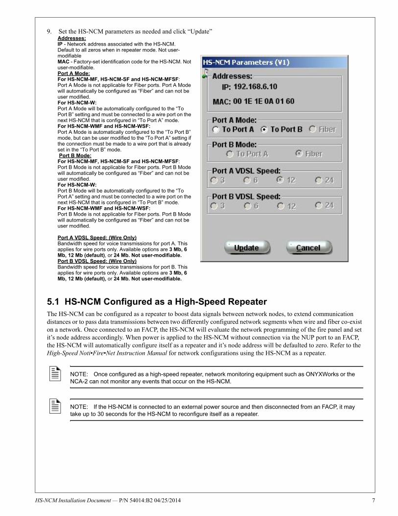
9. Set the HS-NCM parameters as needed and click “Update”
5.1 HS-NCM Configured as a High-Speed RepeaterThe HS-NCM can be configured as a repeater to boost data signals between network nodes, to extend communication distances or to pass data transmissions between two differently configured network segments when wire and fiber co-exist on a network. Once connected to an FACP, the HS-NCM will evaluate the network programming of the fire panel and set it’s node address accordingly. When power is applied to the HS-NCM without connection via the NUP port to an FACP, the HS-NCM will automatically configure itself as a repeater and it’s node address will be defaulted to zero. Refer to the High-Speed Noti•Fire•Net Instruction Manual for network configurations using the HS-NCM as a repeater.
NOTE: Once configured as a high-speed repeater, network monitoring equipment such as ONYXWorks or the NCA-2 can not monitor any events that occur on the HS-NCM.
NOTE: If the HS-NCM is connected to an external power source and then disconnected from an FACP, it may take up to 30 seconds for the HS-NCM to reconfigure itself as a repeater.
Addresses:IP - Network address associated with the HS-NCM. Default to all zeros when in repeater mode. Not user-modifiableMAC - Factory-set identification code for the HS-NCM. Not user-modifiable.Port A Mode:For HS-NCM-MF, HS-NCM-SF and HS-NCM-MFSF:Port A Mode is not applicable for Fiber ports. Port A Mode will automatically be configured as “Fiber” and can not be user modified.For HS-NCM-W:Port A Mode will be automatically configured to the “To Port B” setting and must be connected to a wire port on the next HS-NCM that is configured in “To Port A” mode.For HS-NCM-WMF and HS-NCM-WSF:Port A Mode is automatically configured to the “To Port B” mode, but can be user modified to the “To Port A” setting if the connection must be made to a wire port that is already set in the “To Port B” mode. Port B Mode:For HS-NCM-MF, HS-NCM-SF and HS-NCM-MFSF:Port B Mode is not applicable for Fiber ports. Port B Mode will automatically be configured as “Fiber” and can not be user modified.For HS-NCM-W:Port B Mode will be automatically configured to the “To Port A” setting and must be connected to a wire port on the next HS-NCM that is configured in “To Port B” mode.For HS-NCM-WMF and HS-NCM-WSF:Port B Mode is not applicable for Fiber ports. Port B Mode will automatically be configured as “Fiber” and can not be user modified.
Port A VDSL Speed: (Wire Only)Bandwidth speed for voice transmissions for port A. This applies for wire ports only. Available options are 3 Mb, 6 Mb, 12 Mb (default), or 24 Mb. Not user-modifiable.Port B VDSL Speed: (Wire Only)Bandwidth speed for voice transmissions for port B. This applies for wire ports only. Available options are 3 Mb, 6 Mb, 12 Mb (default), or 24 Mb. Not user-modifiable.
-NCM Installation Document — P/N 54014:B2 04/25/2014 7
8
6 Installation
6.1 Mounting OptionsThe HS-NCM is designed to mount in a variety of CAB-3/CAB-4 compatible chassis, in the NFS-320 enclosure, on a BMP-1 blank plate for dress panel mounting, or behind the DVC-EM in the CA-1 or CA-2 audio chassis. HS-NCM-W can be door-mounted; HS-NCM-MF, HS-NCM-SF, HS-NCM-WMF, HS-NCM-WSF, or HS-NCM-MFSF must be installed in a stationary location. Recommended location is in the top row under the backbox’s knockout, so as to avoid over-bending fiber-optic cable. Avoid mounting other option boards in front of HS-NCM so that its LEDs are visible. Attach the HS-NCM using the four screws that ship with it.
Cabinet-mounting HS-NCM-W/HS-NCM-MF/HS-NCM-SF/HS-NCM-WMF/HS-NCM-WSF/HS-NCM-MFSF:
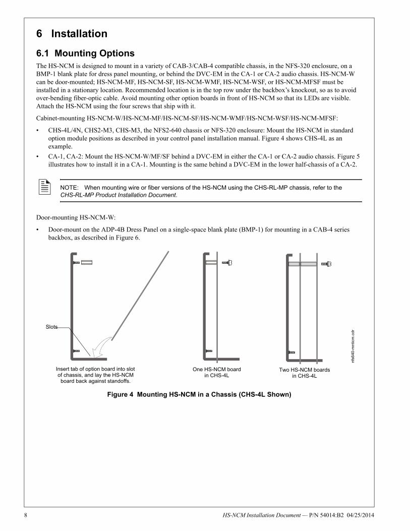
• CHS-4L/4N, CHS2-M3, CHS-M3, the NFS2-640 chassis or NFS-320 enclosure: Mount the HS-NCM in standard option module positions as described in your control panel installation manual. Figure 4 shows CHS-4L as an example.
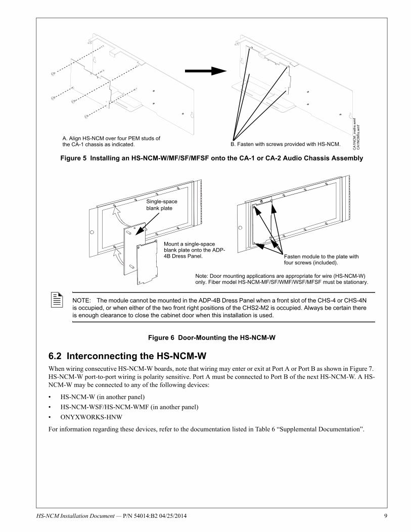
• CA-1, CA-2: Mount the HS-NCM-W/MF/SF behind a DVC-EM in either the CA-1 or CA-2 audio chassis. Figure 5 illustrates how to install it in a CA-1. Mounting is the same behind a DVC-EM in the lower half-chassis of a CA-2.
Door-mounting HS-NCM-W:
• Door-mount on the ADP-4B Dress Panel on a single-space blank plate (BMP-1) for mounting in a CAB-4 series backbox, as described in Figure 6.
Figure 4 Mounting HS-NCM in a Chassis (CHS-4L Shown)
NOTE: When mounting wire or fiber versions of the HS-NCM using the CHS-RL-MP chassis, refer to the CHS-RL-MP Product Installation Document.
nfs6
40-m
ntic
m.c
dr
Insert tab of option board into slot of chassis, and lay the HS-NCM
board back against standoffs.
Slots
One HS-NCM board in CHS-4L
Two HS-NCM boards in CHS-4L
HS-NCM Installation Document — P/N 54014:B2 04/25/2014
HS
Figure 5 Installing an HS-NCM-W/MF/SF/MFSF onto the CA-1 or CA-2 Audio Chassis Assembly
Figure 6 Door-Mounting the HS-NCM-W
6.2 Interconnecting the HS-NCM-WWhen wiring consecutive HS-NCM-W boards, note that wiring may enter or exit at Port A or Port B as shown in Figure 7. HS-NCM-W port-to-port wiring is polarity sensitive. Port A must be connected to Port B of the next HS-NCM-W. A HS-NCM-W may be connected to any of the following devices:
• HS-NCM-W (in another panel)
• HS-NCM-WSF/HS-NCM-WMF (in another panel)
• ONYXWORKS-HNW
For information regarding these devices, refer to the documentation listed in Table 6 “Supplemental Documentation”.
NOTE: The module cannot be mounted in the ADP-4B Dress Panel when a front slot of the CHS-4 or CHS-4N is occupied, or when either of the two front right positions of the CHS2-M2 is occupied. Always be certain there is enough clearance to close the cabinet door when this installation is used.
A. Align HS-NCM over four PEM studs of the CA-1 chassis as indicated. B. Fasten with screws provided with HS-NCM.
CA
1NC
M_
inst
hs.w
mf
CA
1NC
Mh
s.w
mf
Mount a single-space blank plate onto the ADP-4B Dress Panel.
Single-space blank plate
Fasten module to the plate with four screws (included).
Note: Door mounting applications are appropriate for wire (HS-NCM-W) only. Fiber model HS-NCM-MF/SF/WMF/WSF/MFSF must be stationary.
-NCM Installation Document — P/N 54014:B2 04/25/2014 9
10
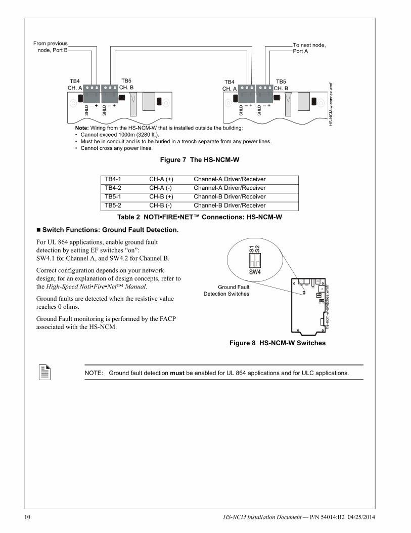
Figure 7 The HS-NCM-W
Switch Functions: Ground Fault Detection.
For UL 864 applications, enable ground fault detection by setting EF switches “on”: SW4.1 for Channel A, and SW4.2 for Channel B.
Correct configuration depends on your network design; for an explanation of design concepts, refer to the High-Speed Noti•Fire•Net™ Manual.
Ground faults are detected when the resistive value reaches 0 ohms.
Ground Fault monitoring is performed by the FACP associated with the HS-NCM.
TB4-1 CH-A (+) Channel-A Driver/Receiver
TB4-2 CH-A (-) Channel-A Driver/Receiver
TB5-1 CH-B (+) Channel-B Driver/Receiver
TB5-2 CH-B (-) Channel-B Driver/Receiver
Table 2 NOTI•FIRE•NET™ Connections: HS-NCM-W
NOTE: Ground fault detection must be enabled for UL 864 applications and for ULC applications.
Note: Wiring from the HS-NCM-W that is installed outside the building: • Cannot exceed 1000m (3280 ft.).• Must be in conduit and is to be buried in a trench separate from any power lines.• Cannot cross any power lines.
From previousnode, Port B
To next node, Port A
HS
-NC
M-w
-con
nex.
wm
f
SH
LD
SH
LD
SH
LD
SH
LD
– + – + – + – +
TB4 CH. A
TB5 CH. B
TB4 CH. A
TB5 CH. B
hs-
ncm
-w-s
witc
hes.
wm
fr
Figure 8 HS-NCM-W Switches
Ground FaultDetection Switches
HS-NCM Installation Document — P/N 54014:B2 04/25/2014
HS
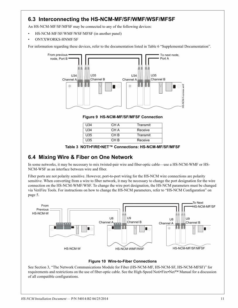
6.3 Interconnecting the HS-NCM-MF/SF/WMF/WSF/MFSF An HS-NCM-MF/SF/MFSF may be connected to any of the following devices:
• HS-NCM-MF/SF/WMF/WSF/MFSF (in another panel)
• ONYXWORKS-HNMF/SF
For information regarding these devices, refer to the documentation listed in Table 6 “Supplemental Documentation”.
Figure 9 HS-NCM-MF/SF/MFSF Connection
6.4 Mixing Wire & Fiber on One Network In some networks, it may be necessary to mix twisted-pair wire and fiber-optic cable—use a HS-NCM-WMF or HS-NCM-WSF as an interface between wire and fiber.
Fiber ports are not polarity sensitive. However, port-to-port wiring for the HS-NCM wire connections are polarity sensitive. When converting from a wire to fiber network, it may be necessary to change the port designation for the wire connection on the HS-NCM-WMF/WSF. To change the wire port designation, the HS-NCM parameters must be changed via VeriFire Tools. For instructions on how to change the HS-NCM parameters, refer to “HS-NCM Configuration” on page 5.
Figure 10 Wire-to-Fiber Connections
See Section 3, “The Network Communications Module for Fiber (HS-NCM-MF, HS-NCM-SF, HS-NCM-MFSF)” for requirements and restrictions on the use of fiber-optic cable. See the High-Speed Noti•Fire•Net™ Manual for a discussion of all compatible configurations.
U34 CH A Transmit
U34 CH A Receive
U35 CH B Transmit
U35 CH B Receive
Table 3 NOTI•FIRE•NET™ Connections: HS-NCM-MF/SF/MFSF
HS
-NC
M-f
-co
nnex
.wm
f
From previousnode, Port B
To next node, Port A
U35Channel B
U35Channel B
U34Channel A
U34Channel A
FromPrevious
HS-NCM-W
To Next HS-NCM-MF/SF
HS-NCM-W HS-NCM-WMF/WSF HS-NCM-MF/SF/MFSF
U9Channel B
U8Channel A
U9Channel B
U8Channel A
-NCM Installation Document — P/N 54014:B2 04/25/2014 11
12
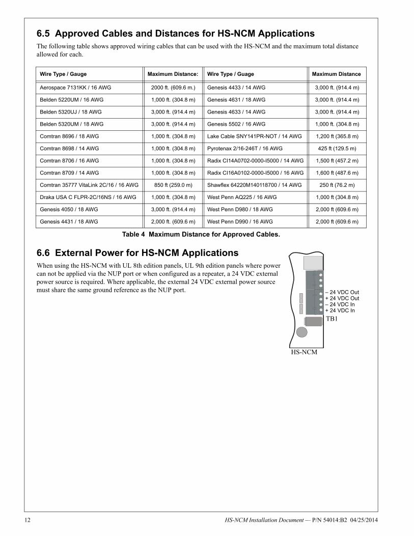
6.5 Approved Cables and Distances for HS-NCM ApplicationsThe following table shows approved wiring cables that can be used with the HS-NCM and the maximum total distance allowed for each.
6.6 External Power for HS-NCM ApplicationsWhen using the HS-NCM with UL 8th edition panels, UL 9th edition panels where power can not be applied via the NUP port or when configured as a repeater, a 24 VDC external power source is required. Where applicable, the external 24 VDC external power source must share the same ground reference as the NUP port.
Wire Type / Gauge Maximum Distance: Wire Type / Guage Maximum Distance
Aerospace 7131KK / 16 AWG 2000 ft. (609.6 m.) Genesis 4433 / 14 AWG 3,000 ft. (914.4 m)
Belden 5220UM / 16 AWG 1,000 ft. (304.8 m) Genesis 4631 / 18 AWG 3,000 ft. (914.4 m)
Belden 5320UJ / 18 AWG 3,000 ft. (914.4 m) Genesis 4633 / 14 AWG 3,000 ft. (914.4 m)
Belden 5320UM / 18 AWG 3,000 ft. (914.4 m) Genesis 5502 / 16 AWG 1,000 ft. (304.8 m)
Comtran 8696 / 18 AWG 1,000 ft. (304.8 m) Lake Cable SNY141PR-NOT / 14 AWG 1,200 ft (365.8 m)
Comtran 8698 / 14 AWG 1,000 ft. (304.8 m) Pyrotenax 2/16-246T / 16 AWG 425 ft (129.5 m)
Comtran 8706 / 16 AWG 1,000 ft. (304.8 m) Radix CI14A0702-0000-I5000 / 14 AWG 1,500 ft (457.2 m)
Comtran 8709 / 14 AWG 1,000 ft. (304.8 m) Radix CI16A0102-0000-I5000 / 16 AWG 1,600 ft (487.6 m)
Comtran 35777 VitaLink 2C/16 / 16 AWG 850 ft (259.0 m) Shawflex 64220M140118700 / 14 AWG 250 ft (76.2 m)
Draka USA C FLPR-2C/16NS / 16 AWG 1,000 ft. (304.8 m) West Penn AQ225 / 16 AWG 1,000 ft (304.8 m)
Genesis 4050 / 18 AWG 3,000 ft. (914.4 m) West Penn D980 / 18 AWG 2,000 ft (609.6 m)
Genesis 4431 / 18 AWG 2,000 ft. (609.6 m) West Penn D990 / 16 AWG 2,000 ft (609.6 m)
Table 4 Maximum Distance for Approved Cables.
– 24 VDC Out+ 24 VDC Out– 24 VDC In+ 24 VDC In
TB1
HS-NCM
HS-NCM Installation Document — P/N 54014:B2 04/25/2014
HS
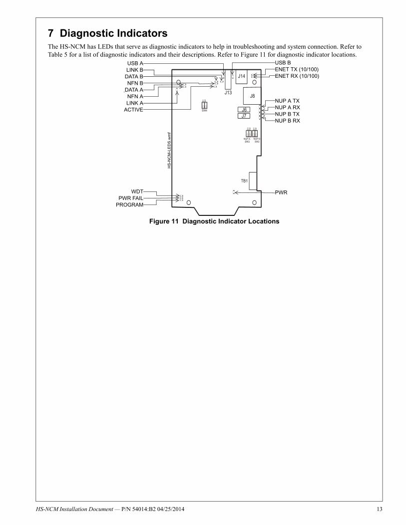
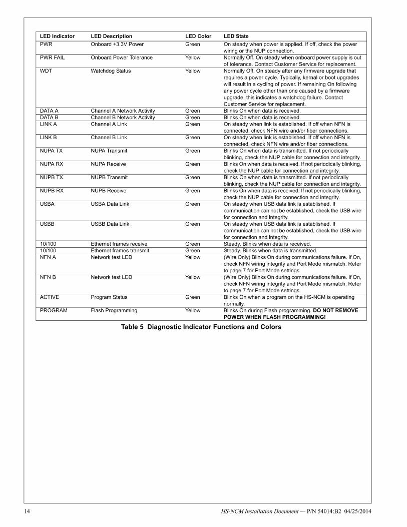
7 Diagnostic Indicators The HS-NCM has LEDs that serve as diagnostic indicators to help in troubleshooting and system connection. Refer to Table 5 for a list of diagnostic indicators and their descriptions. Refer to Figure 11 for diagnostic indicator locations.
HS
-NC
M-L
ED
S.w
mf
Figure 11 Diagnostic Indicator Locations
NUP A TXNUP A RXNUP B TXNUP B RX
PWRWDTPWR FAIL
PROGRAM
USB ALINK B
DATA BNFN B
DATA ANFN ALINK A
ACTIVE
USB BENET TX (10/100)ENET RX (10/100)
-NCM Installation Document — P/N 54014:B2 04/25/2014 13
14
LED Indicator LED Description LED Color LED State
PWR Onboard +3.3V Power Green On steady when power is applied. If off, check the power wiring or the NUP connection.
PWR FAIL Onboard Power Tolerance Yellow Normally Off. On steady when onboard power supply is out of tolerance. Contact Customer Service for replacement.
WDT Watchdog Status Yellow Normally Off. On steady after any firmware upgrade that requires a power cycle. Typically, kernal or boot upgrades will result in a cycling of power. If remaining On following any power cycle other than one caused by a firmware upgrade, this indicates a watchdog failure. Contact Customer Service for replacement.
DATA A Channel A Network Activity Green Blinks On when data is received.DATA B Channel B Network Activity Green Blinks On when data is received.LINK A Channel A Link Green On steady when link is established. If off when NFN is
connected, check NFN wire and/or fiber connections.LINK B Channel B Link Green On steady when link is established. If off when NFN is
connected, check NFN wire and/or fiber connections.NUPA TX NUPA Transmit Green Blinks On when data is transmitted. If not periodically
blinking, check the NUP cable for connection and integrity.NUPA RX NUPA Receive Green Blinks On when data is received. If not periodically blinking,
check the NUP cable for connection and integrity.NUPB TX NUPB Transmit Green Blinks On when data is transmitted. If not periodically
blinking, check the NUP cable for connection and integrity.NUPB RX NUPB Receive Green Blinks On when data is received. If not periodically blinking,
check the NUP cable for connection and integrity.USBA USBA Data Link Green On steady when USB data link is established. If
communication can not be established, check the USB wire for connection and integrity.
USBB USBB Data Link Green On steady when USB data link is established. If communication can not be established, check the USB wire for connection and integrity.
10/100 Ethernet frames receive Green Steady, Blinks when data is received.10/100 Ethernet frames transmit Green Steady. Blinks when data is transmitted.NFN A Network test LED Yellow (Wire Only) Blinks On during communications failure. If On,
check NFN wiring integrity and Port Mode mismatch. Refer to page 7 for Port Mode settings.
NFN B Network test LED Yellow (Wire Only) Blinks On during communications failure. If On, check NFN wiring integrity and Port Mode mismatch. Refer to page 7 for Port Mode settings.
ACTIVE Program Status Green Blinks On when a program on the HS-NCM is operating normally.
PROGRAM Flash Programming Yellow Blinks On during Flash programming. DO NOT REMOVE POWER WHEN FLASH PROGRAMMING!
Table 5 Diagnostic Indicator Functions and Colors
HS-NCM Installation Document — P/N 54014:B2 04/25/2014
HS
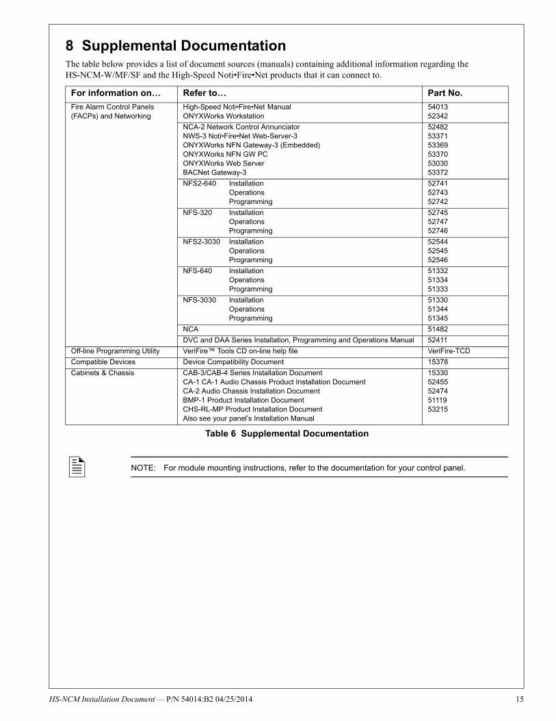
8 Supplemental Documentation The table below provides a list of document sources (manuals) containing additional information regarding the HS-NCM-W/MF/SF and the High-Speed Noti•Fire•Net products that it can connect to.
For information on… Refer to… Part No.
Fire Alarm Control Panels (FACPs) and Networking
High-Speed Noti•Fire•Net ManualONYXWorks Workstation
5401352342
NCA-2 Network Control AnnunciatorNWS-3 Noti•Fire•Net Web-Server-3ONYXWorks NFN Gateway-3 (Embedded)ONYXWorks NFN GW PCONYXWorks Web ServerBACNet Gateway-3
524825337153369533705303053372
NFS2-640 InstallationOperationsProgramming
527415274352742
NFS-320 InstallationOperationsProgramming
527455274752746
NFS2-3030 InstallationOperationsProgramming
525445254552546
NFS-640 InstallationOperationsProgramming
513325133451333
NFS-3030 InstallationOperationsProgramming
513305134451345
NCA 51482
DVC and DAA Series Installation, Programming and Operations Manual 52411
Off-line Programming Utility VeriFire™ Tools CD on-line help file VeriFire-TCD
Compatible Devices Device Compatibility Document 15378
Cabinets & Chassis CAB-3/CAB-4 Series Installation DocumentCA-1 CA-1 Audio Chassis Product Installation DocumentCA-2 Audio Chassis Installation DocumentBMP-1 Product Installation DocumentCHS-RL-MP Product Installation DocumentAlso see your panel’s Installation Manual
1533052455524745111953215
Table 6 Supplemental Documentation
NOTE: For module mounting instructions, refer to the documentation for your control panel.
-NCM Installation Document — P/N 54014:B2 04/25/2014 15