Embed Size (px)
Citation preview
8/11/2019 PND_Wave Barrier_2013.pdf
http://slidepdf.com/reader/full/pndwave-barrier2013pdf 1/12
P O O R S O I L S , H A R S H M A R
I ,
E N V I R O N M E N T , D Y N A M I
E N V I R M E T, DY I WAV E L OA D S, P O O R S O I L
,
S E D I M E N T A T I O N, S C O U R ,
S D I N A I S R
C O R R O S I O N , V A R I A B L E
C R O I O N, VA R I L E
T I D E S , I C E , E A R T H Q UA K
I I ,
S H O R E L I N E E R O S I O N, P O
S E L I E R I O N, P
O I L S , H A R S H M A R I N E
E N V I R O N M E N T , D Y N A M I
E V I R E , I
WAV E L OA D S, P O O R S O I L
W E A D , O O R O I L
S E D I M E N T A T I O N, S C O U R ,
C O R R O S I O N , V A R I A B L E
C R O I O N, VA R I L E
T I D E S , I C E , E A R T H Q UA K
S H O R E L I N E E R O S I O N, P O
S E I E R I , P
O I L S , H A R S H M A R I N E
O I L S , H A R H I NE N V I R O N M E N T , D Y N A M I
V
WAV E L OA D S, P O O R S O I L
W E A D , O R O I L
S E D I M E N T A T I O N, S C O U R ,
BREAKWATERSINCLUDING PARTIAL PENETRATING
WAV E BA R R I E R S
P N DE NGINEERS, I NC.
8/11/2019 PND_Wave Barrier_2013.pdf
http://slidepdf.com/reader/full/pndwave-barrier2013pdf 2/12
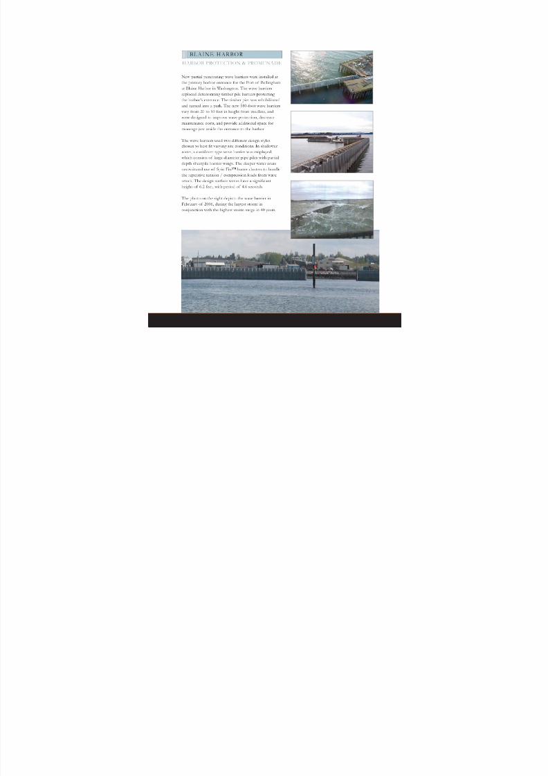
PND | BREAKWATERS
A breakwater is a structure protecting a harbor,
anchorage or shoreline from waves. There are
essentially three types: rubble-mound, vertical
wall, and floating.
PND’s coastal engineers are experienced in
designing all types of breakwaters and jetties,
through all the phases of projects, from conceptdesign through construction.
B REAK W AT ERS
PND has specialists in
oceanography, coastal engineering
and marine construction. Specialists
have direct project experience that
includes all five shorelines of North
America (Arctic, Pacific, Gulf of
Mexico, Atlantic and Great Lakes) in
addition to projects overseas.

8/11/2019 PND_Wave Barrier_2013.pdf
http://slidepdf.com/reader/full/pndwave-barrier2013pdf 3/12
DESIGN CHALLENGES
Breakwater design is a challenging field in which designers
must rely upon sound judgment and experience to
efficiently solve problems associated with uncertainties in
various environmental conditions. Relative to other
engineering professions, design standards and codes often
do not address the wide array of potential design
conditions. Design demands the expertise and experience
of those who specialize in coastal engineering.
PND is well-qualified to analyze wind, wave, tide and
currents to determine wall heights, depths, and allowable
wave transmission for any number of site conditions,
including hindcast studies and wave reflection/refraction
analysis. PND also has experience in specialized areas that
can significantly affect project performance including boat
wakes, scour, propwash and corrosion protection.
BREAKWATER TYPES
The choice of a breakwater type is largely dependent on
wave height and period. The largest waves require rubble-
mound structures that are able to absorb wave energy.
Floating breakwaters can be used for smaller wave heights
and periods, and allow for transient moorage space.
Vertical structural wall types address the range falling
between that of rubble-mound and floating breakwaters,
as shown in the diagram on the right.
PND has designed breakwaters in alarge range of site conditions:
• Dynamic Wave Loads
• Poor Soils
• Scour
• Corrosion
• Sensitive Ecosystems with Stringent
Permitting Requirements
• Extremely Variable Tides
• Ice
• Earthquakes
• Shoreline Erosion/Accretion
Structure Types for Typical Range of
Wave Height & Per iod
30
25
20
15
10
5
5 10 15 20 25 30
W a v e H e i g h t ( f e e t )
Wave Period (seconds)
Full-Height VerticalStructural Wall
Rubble-Mound and Filled Structures
Floating
Partial Penetrating Vertical Wall

8/11/2019 PND_Wave Barrier_2013.pdf
http://slidepdf.com/reader/full/pndwave-barrier2013pdf 4/12
TRADITIONAL BREAKWATER STRUCTURES
PND | BREAKWATERS
ST. GEORGE RUBBLE-MOUND BREAKWATER
In the Pribilof Islands in Alaska, this rubble-mound, berm-type breakwater was
originally designed by PND in the early 1980’s. It provides moorage and safe
refuge for a fishing fleet. Physical conditions at St. George are extremely harsh,
with heavy icing and waves that reach up to 42 feet high.
After 22 years of extreme storms, a massive storm hit that caused non-critical
breakwater damage. Due to the exceptional past performance, PND was asked to
provide design repairs. Eight thousand cubic yards of quarry rock ranging from
50-2,500 pounds were required on the north shoreline, topped with 8,000 tons of
armor rock. The south breakwater arm required 18,000 tons of armor rock.
CASCADE POINT MARINE FACILITY BREAKWATER
Cascade Point is the site of a rubble-mound breakwater that will protect f loats
and a dock for a gold mine near Juneau, Alaska. The site is constrained by
relatively steep underwater slopes and the breakwater is designed to accommodate
future expansion. The typical armor rock size is nominally four feet in diameter. A
cross-section of the breakwater is shown below.

8/11/2019 PND_Wave Barrier_2013.pdf
http://slidepdf.com/reader/full/pndwave-barrier2013pdf 5/12
PORT ORCHARD WEST BREAKWATER
PND provided design for a floating breakwater at the Port
Orchard Marina on Washington’s Puget Sound that protects the
marina and serves as transient moorage. The marina has waves of
up to four feet in height.
LA CONNER G-FLOAT
G-Float is a floating breakwater that provides protection for the
La Conner Marina North Basin in Washington. The breakwater is
an 800-foot x 9-foot modular concrete float on the marina’s outer
perimeter and also provides transient moorage.
Port Orchard West Breakwater is located
on the west side of the marina (to the
right of the above photograph).
The La Conner breakwater is located on
the west side of the marina (in the front
of the photograph).
8/11/2019 PND_Wave Barrier_2013.pdf
http://slidepdf.com/reader/full/pndwave-barrier2013pdf 6/12

8/11/2019 PND_Wave Barrier_2013.pdf
http://slidepdf.com/reader/full/pndwave-barrier2013pdf 7/12

8/11/2019 PND_Wave Barrier_2013.pdf
http://slidepdf.com/reader/full/pndwave-barrier2013pdf 8/12PND | BREAKWATERS
A partial penetrating wave barrier in Astoria, Oregon provided expansion room
for 22 additional 60-foot vessel slips by eliminating a filled bulkhead system. The
alignment of the new breakwater allowed for the additional moorage.
The West Basin marina is located near the mouth of the Columbia River in
Oregon where there are strong currents, high winds and ocean-going cargo
vessels. The largest design loads are developed by 4.9-foot high significant waves
with 4.3-second periods. A cantilever-style wall was selected that consists of
large-diameter pipe piles with sheetpile barrier wings. This design provided the
best wall alignment to protect the harbor without impeding access and creating
wave-reflection issues. A typical sect ion is shown to the right .
WEST BASIN WAVE BARRIER
HARBOR PROTECTION & EXPANSION
The top photo shows the West Basin
prior to breakwater construction. Thelarge photograph depicts the 22 additional
moorage locations.
CLEAR
ZONE
8/11/2019 PND_Wave Barrier_2013.pdf
http://slidepdf.com/reader/full/pndwave-barrier2013pdf 9/12

8/11/2019 PND_Wave Barrier_2013.pdf
http://slidepdf.com/reader/full/pndwave-barrier2013pdf 10/12
PND | BREAKWATERS
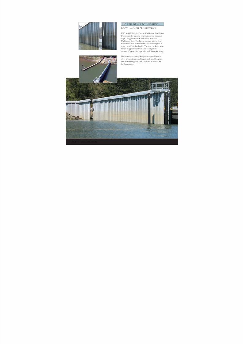
PND provided services to the Washington State Parks
Department for a partial penetrating wave barrier at
Cape Disappointment State Park in Southern
Washington State. The bar rier protects a three-lane
recreational boat launch facility, and was designed to
replace an old timber barrier. The new cantilever wave
barrier is approximately 250 feet in length and
consists of galvanized pipe piles with sheet pile wings.
The partial penetrating design was selected because
of its low environmental impact and small footprint.
The barrier design also has a separation that allows
for fish passage.
CAPE DISAPPOINTMENT
BOAT LAUNCH PROTECTION

8/11/2019 PND_Wave Barrier_2013.pdf
http://slidepdf.com/reader/full/pndwave-barrier2013pdf 11/12
BELL STREET PIER
CRUISE SHIP FACILITY
Bell Street Pier is a waterfront facility in
downtown Seattle, Washington that provides
public moorage, cruise ship operations, a
maritime museum, a conference facility, and
waterfront restaurants. The harbor is protected with a 900-foot partial penetrating wave barrier
with lateral resis tant battered Spin Fin™ piles.
The wave barrier was designed to resist storms
producing 8-foot significant height waves with
six-second periods. The wave barrier face
extends into the water 32 feet at low tide. It is
comprised of 48-inch diameter pipe piles placed
12 feet on-center acting as the vertical bending
members. Bridging the gap between these pilesare eight-inch-thick prestressed concrete panels.
The height of the structure from mudline varies
between 55 and 75 feet.
A three-dimensional wave model of the
surrounding Elliot Bay (bottom right) was used
to verify wave climate and barrier efficiency at
B.C. Research Lab in Vancouver, Canada.

8/11/2019 PND_Wave Barrier_2013.pdf
http://slidepdf.com/reader/full/pndwave-barrier2013pdf 12/12


![H20youryou[2] · 2020. 9. 1. · 65 pdf pdf xml xsd jpgis pdf ( ) pdf ( ) txt pdf jmp2.0 pdf xml xsd jpgis pdf ( ) pdf pdf ( ) pdf ( ) txt pdf pdf jmp2.0 jmp2.0 pdf xml xsd](https://img.pdfslide.net/doc/110x75/60af39aebf2201127e590ef7/h20youryou2-2020-9-1-65-pdf-pdf-xml-xsd-jpgis-pdf-pdf-txt-pdf-jmp20.jpg)


