Embed Size (px)
Citation preview

PNEUMATIC BELT SANDERPlease read this manual carefully before you attempt to use your tool so that you may use it properly and safely.
BELTON Model B-10N, B-20N, B-20NB, B-30NPROFESSIONAL TOOL
SpecificationsModel B-10N B-20N B-20NB B-30N
Maximum Operating Pressure 0.6 MPa
Air Consumption (No Load) 0.4 m3/min 0.52 m3/min 0.52 m3/min 0.68 m3/min
Rated Speed (No Load) 17000 r/min(min−1) 17000 r/min(min−1) 17000 r/min(min−1) 14000 r/min(min−1)
Standard Belt Size10×330mm
(25/64″×13″)20×520mm
(25/32″×20-15/32″)30×540 mm
(1-3/16″×21-17/16″)
Mass (Weight) 0.7 kg 1.2 kg 1.2 kg 2.4 kg
Sound Pressure Level 78 dB (A) 83 dB (A) 85 dB (A) 82 dB (A)
Sound Power Level 89 dB (A) 94 dB (A) 96 dB (A) 93 dB (A)
Vibration Level 1.28 m/s2 0.80 m/s2 0.75 m/s2Handle : 1.53 m/s2
Grip : 0.45 m/s2
Thread Size of Air Inlet Rc 1/4
B-10N B-20N
B-20NB B-30N
Original Instructions
The specifications and configurations contained in this document are subject to change without prior notice due to improvements we are making day in, day out.
Manufactured by :
NITTO KOHKI Co., Ltd.2-9-4, Nakaikegami, Ohta-ku, Tokyo, 146-8555, JapanTEL : (81)-3-3755-1111 FAX : (81)-3-3753-8791E-mail : [email protected] : www.nitto-kohki.co.jp
Keep the manual handy – so you can use it whenever necessary.

1
The following Safety notations are used throughout the manual to highlight safety precautions for the user and for the tool.
Warning: Indicates a potentially hazardous situation which, if not avoided by following the
instructions given, could result in death or serious injury.
Caution: Indicates a potentially hazardous situation which, if not avoided by following the
instructions given, could result in injury or material damage.
Please note, however, that failure to observe safety precautions under the “ Caution” category could result in a serious occurrence depending on the situation: please observe all safety precautions in the manual. Caution: Important precautions for tool setup, operation and maintenance.
Thank you very much for your purchase of this Nitto Kohki product. Before using your tool, please read this manual carefully so that you may use it properly to get the most out of it.Please keep the manual handy - so you can use it whenever necessary.
・ English : Please ask your dealer or distributor for instruction manual in local language(s).
・ German : Bitte fragen Sie lhren Händler nach eine Betriebsanleitung in Landessprache.
・ French : S'il vous plait, veuillez demandez á votre foumisseur de manuel instruction en langue locale.
・ Spanish : Por favor, cantacte con su distribuidor para el manual de instrucciones en español.
・ Portuguese : Por favor pessa ao seo agente ou distribuidor o manual de instrucces ih linguagen local.
・ Italian : Per Manuale Istruzioni in lingua locale Vi preghiamo di rivolgervi al rivenditore o distributore.
・ Dutch : Vraag uw handelaar om een nederladstalige gebruiksaanwijzing.
・ Swedish : Be er lokala Åtreförsäljare eller distributör om manualer pá svenska.
・ Danish : Venligst henvend Dem til den danske distributør for instructions manualer.
・ Polish : Prosze pytac swojego dealera lub dystrybutora o instrukcje obslugi w jezyku localnym.
・ 中文 : 請向當地供應商或経銷商詢問中文使用説明書
CONTENTS pageIMPORTANT SAFETY INSTRUCTIONS …………………… 2GENERAL: TOOLS …………………………………………… 2GENERAL: PNEUMATIC TOOLS ………………………… 3INSTRUCTIONS FOR THIS TOOL ………………………… 4 1. USAGE …………………………………………………… 4 2. CHECK THE CONTENTS OF THE PACKAGE ……… 4 3. AIR SUPPLY ……………………………………………… 4 4. PREPARATION …………………………………………… 5 5. HOW TO OPERATE THE TOOL ……………………… 6 6. THREAD SIZE OF HOSE FITTING …………………… 9 7. STORAGE ………………………………………………… 9 8. OPTIONAL PARTS ……………………………………… 9 9. ORDERING SERVICE PARTS ………………………… 910. EXPLODED DIAGRAM: B-10N ……………………… 1011. EXPLODED DIAGRAM: B-20N ……………………… 1112. EXPLODED DIAGRAM: B-20NB …………………… 1213. EXPLODED DIAGRAM: B-30N ……………………… 13
PICTOGRAM
Warning: It might be dangerous to operate the tool if the instructions supplied are not followed.
Using this tool improperly could result in serious injury. Read the instruction manual before using.
Always wear suitable eye protection.
Always wear suitable hearing protection.
Always wear respiratory protective equipment (PPE).

2
IMPORTANT SAFETY INSTRUCTIONS
When using the tool, please observe the safety precautions below to prevent possible accident or injury.
GENERAL: TOOLSWarning
TO OPERATORS● Wear proper clothing for the type of work being
done.Take care to avoid entanglement with the moving parts of the tool with clothing, ties, hair etc. If items become entangled it will cause the operator to be pulled towards the tool and lead to possible cause of accident or injury.
● Always wear suitable eye protection. Remember, regular glasses are not safety glasses. The lenses are only shock resistant, which will not give you sufficient eye protection you may need in your working environment.
● Always wear suitable hearing protection. ● Wear respiratory protective equipment (PPE).
Wear respiratory protective equipment (PPE) when working in an environment where dust particles are generated in operation.
● Avoid working posture that is too stressful. Always ensure a firm footing and well balanced posture.
● Do not operate the tool if you are too tired. ● Never touch any moving parts of the tool when
running.
ABOUT WORK AREA● Keep the work area clean.
Cluttered work areas (e.g. workbench) invite accidents.
● Carefully select the work area.Do not expose tool to rain.Do not use tool in a wet or soaked area.See that the work area is adequately illuminated.
● Never work near inflammable liquid or in a potentially explosive atmosphere.
● Keep children away from the work area.Keep children and unauthorized people away from the work area to avoid accident or injury.
BEFORE OPERATION● Inspect tool before use.
Before using, check that screws are securely tightened, that any protective cover or guard is securely in place, other parts are free from damage and that the tool runs as it should.Check that moving parts are properly adjusted for positioning and tightened, that parts are free from damage and properly mounted, and that all other parts are in good condition for normal operation.Should you find any damage to the protective cover or other part, replace it in accordance with the Operation Manual. If there are no instructions in the Manual, please contact the sales agent through which you have purchased your tool or an authorized dealer near you for repair.Likewise, if a switch failure occurs, contact sales agent through which you have purchased your tool or an authorized dealer near you for repair.Do not use the tool if it does not start or stop with the start/stop switch.
● Securely mount cutterAn improperly mounted cutter may fly out, causing possible damage to the tool or injury to the operator.
● Always remove spanner, wrench, etc., once adjustment has been made with them.
● Use a tool appropriate for the application.Avoid heavy-duty application that is beyond the capacity of tool.
● Do not use the tool for purposes other than what it is designed for.
● Do not abuse tool. Use tool in accordance with the specifications: you’ll get the most out of it while ensuring safety.
● Securely fasten workpiece in place.Use a vice or clamp to securely fasten the workpiece in place. It is much safer this way than holding it in your hand, allowing you to operate the tool with both hands.
ABOUT HANDLING● How to store tool.
When the tool is not used, store it in a dry area and out of reach of children.
● How to carry tool.Do not touch the start switch while the tool is being carried.
● Do not leave the tool unattended while it is running.Turn off the start switch and disconnect the tool from power source. Do not leave the work area until the tool comes to a complete stop.

3
MAINTENANCE/SERVICE● Do not take apart or modify tool.
Disassembly or modification carried out without the supervision of a qualified or authorized service engineer could result in an accident or injury.
● Inspect cutting tool and accessories, etc. Always check to see that cut t ing too l and accessories, etc. are in good operating condition without damage or deterioration before you mount them on the tool. Should you find any damage to an accessory or part, please contact sales agent through which you have purchased your tool or an authorized dealer near you for repair.
● Check parts for damage. When you have found damage to accessory or other part, carefully check the damaged part to determine the extent of influence it has upon the functions of the tool – that is, determine whether it can still perform its normal functions. Check to see that the linkage of the moving parts is OK, that all parts are OK without damage, that they are properly mounted, and that the tool functions normally. Should you find any damage to an accessory or part that may hamper proper functioning of the tool, please contact sales agent through which you have purchased your tool or an authorized dealer near you for repair.
● Have your tool repaired at an authorized Nitto Service Center.For repair or parts replacement, please contact the sales agent through which you have purchased your tool or an authorized dealer near you.
● Use only Nitto genuine parts. Use of improper parts may result in serious occurrence.To obtain a Nitto genuine part, consult this Manual or contact the sales agent from which you have purchased your tool directly.
● Do not detach label or nameplate from tool. When a label/nameplate gets damaged, worn or becomes missing, contact the sales agent through which you have purchased your tool or Nitto Kohki Co. Ltd, directly for a replacement.
DISPOSALWhen a tool is taken permanently out of service, it is advised that the tool is disassembled, degreased and parts separated by material and recycled locally in the appropriate manner.
GENERAL: PNEUMATIC TOOLS
Warning● Use appropriate air pressure.
Excessively high air pressure will increase the number of revolutions or strokes causing not only potential premature failure/breakage but could also lead to an unexpected accident or injury.
● Connect tool to air supply line.There are various types of pipes running in a factory in addition to the pneumatic line (such as oxygen, nitrogen, gas and water). For this reason, always ensure that you are connecting to the pneumatic line.
● Start tool properly.Turn the start switch OFF before connecting to the air supply line.
● Always disconnect the tool from the air supply line before putting on/taking off any accessory and prior to carrying out any maintenance work.
● Avoid exposure to exhaust air.Pneumatic tool exhaust air contains oi l and contaminated moisture. Make sure the exhaust air is not directed towards your face or anyone else within the work area.
● Keep tool off electricity.This pneumatic tool is not electrically insulated. To avoid a potential electric shock do not use where there is a possibility of coming into contact with live electricity.
Caution● Handle tool carefully.
Abusive use of tool could invite failure or accident.Do not throw, drop or shock the tool.
● Handle air hose carefully.Do not carry the tool by the air hose.Do not pull the air hose to disconnect.

4
INSTRUCTIONS FOR THIS TOOLAbout Your Tool
Warning● Wear protective glasses and a dustproof mask.
Operation generates dust and abrasive particles, etc. which may cause eye and/or respiratory injury: Always use PPE (Personal Protective Equipment) for eye and respiratory protection.
● When you change or adjust the tool or parts, be sure to detach the tool from the air hose.
● Never touch the moving parts while in operation.
Caution● Protect yourself from dust and abrasive particles.
When sanding hot dust and abrasive particles fly off the workpiece: Always wear eye protection glasses, long sleeve protective clothing, gloves (except knitted gloves), foot and leg protection, etc. to protect yourself. Always keep your face away from the sanding surface.
1. USAGEThis is a handheld pneumatic belt sander designed and built to perform sanding operation utilizing a abrasive belt.
2. CHECK THE CONTENTS OF THE PACKAGEUpon unpacking, check to see that the shipment is complete without damage or oil leakage in transport. Should you find any damage or short-shipment, please contact sales agent through which you have purchased your tool or authorized dealer near you for corrective actions.
Model Package Contents Qty
B-10N
B-10N 1 set
Abrasive Belts Z76#60×102 (one of them
mounted)Abrasive Belts Z76#80×10 1Abrasive Belts Z76#100×10 1Abrasive Belts Z76#120×10 1Hex. Socket Screw Key 2 1Hex. Socket Screw Key 4 1Bushing R1/4×NPT1/4 1Instruction Manual 1Declaration of Conformity 1Caution for Use 1
B-20N
B-20N 1 set
Abrasive Belt Z76#60×202 (one of them
mounted)Abrasive Belt Z76#80×20 1Abrasive Belt Z76#100×20 1Abrasive Belt Z76#120×20 1Hex. Socket Screw Key 2.5 1Hex. Socket Screw Key 4 1Bushing R1/4×NPT1/4 1Finger Pad Sub Ass’y 1 setPan Head Screw 5×10 1Pan Head Screw 6×10 1Convex Shoe 1Instruction Manual 1Declaration of Conformity 1Caution for Use 1
B-20NB
B-20NB 1 set
Abrasive Belt Z76#60×202 (one of them
mounted)Abrasive Belt Z76#80×20 1Abrasive Belt Z76#100×20 1Abrasive Belt Z76#120×20 1Hex. Socket Screw Key 4 1Bushing R1/4×NPT1/4 1Finger Pad Sub Ass’y 1 setPan Head Screw 5×10 1Pan Head Screw 6×10 1Convex Shoe 1Instruction Manual 1Declaration of Conformity 1Caution for Use 1
B-30N
B-30N 1 set
Abrasive Belt Z76#60×202 (one of them
mounted)Abrasive Belt Z76#80×20 1Abrasive Belt Z76#100×20 1Silencer Ass’y 1 setHandle Ass’y 1 setHex. Socket Screw Key 4 1Hex. Socket Screw Key 5 1Bushing R1/4×NPT1/4 1Instruction Manual 1Declaration of Conformity 1Caution for Use 1
3. AIR SUPPLY3-1. Air Pressure
Adjust air pressure with the Air Regulator to the level appropriate for the pneumatic tool used.
5
Air pressure that is too low fails the Tool to operate at full capacity.Air pressure that is too high may cause damage to the Tool.
3-2. Air Line (Fig.1)Use a 9.5 mm (3/8”) I.D. Connecting Hose between the Compressor and the Tool.Drained water, etc., if flown into the Tool, could cause Tool failure. Install an Air Filter. between the Compressor and the Tool.
Air RegulatorOiler
Air Filter
Compressor
Lubrication
Tool 9.5mm (3/8”) I.D.Hose
Cupla
Fig. 1
3-3. LubricationInstall an Oiler between the Compressor and the Tool. Use the machine oil ISO VG-10. Failure to lubricate as required may result in damage to the Tool. Use of oil that is too thick will reduce the performance of Tool.
4. PREPARATION4-1. Fastening The Guard
Caution● No clearance should be allowed between the
Housing and the Guard. Any clearance, if there is between them, can cause the Abrasive Belt to come off, resulting in injury to the operator or damage to the equipment or both.
You can set the Guard at any angle you may find best suited for your working posture or the configuration of workpiece. Once you have placed the Guard at a desired angle, tighten the Hex. Socket Head Cap Screw per “A” in Fig. 3 with a Hex. Socket Screw Key. At that time, carefully fasten the Guard so that there is no clearance between the Housing and the Guard.
Fig.2
A
HousingGuard
Carefully fasten the Guard so that there is no clearancebetween the Housing and the Guard.
B-10N, B-20N, B-20NB
Fig.3
4-2. Installing The Finger Pad B-20N, B-20NB (Fig.4)
Caution● Fasten the Finger Pad securely. Failure to do so
may result in injury to the operator or damage to the equipment or both.
Securely fasten the supplied Finger Pad with two Pan Head Screws, 5X10 and 6X10, clamping both sides of the Guard. At that time, the Finger Pad locator should be on the Guard surface.
Pan Head Screw 5X10
Pan Head Screw 6x10
Finger Pad
Finger Pad locator
Guard surface
B-20N, B-20NB
Fig.4
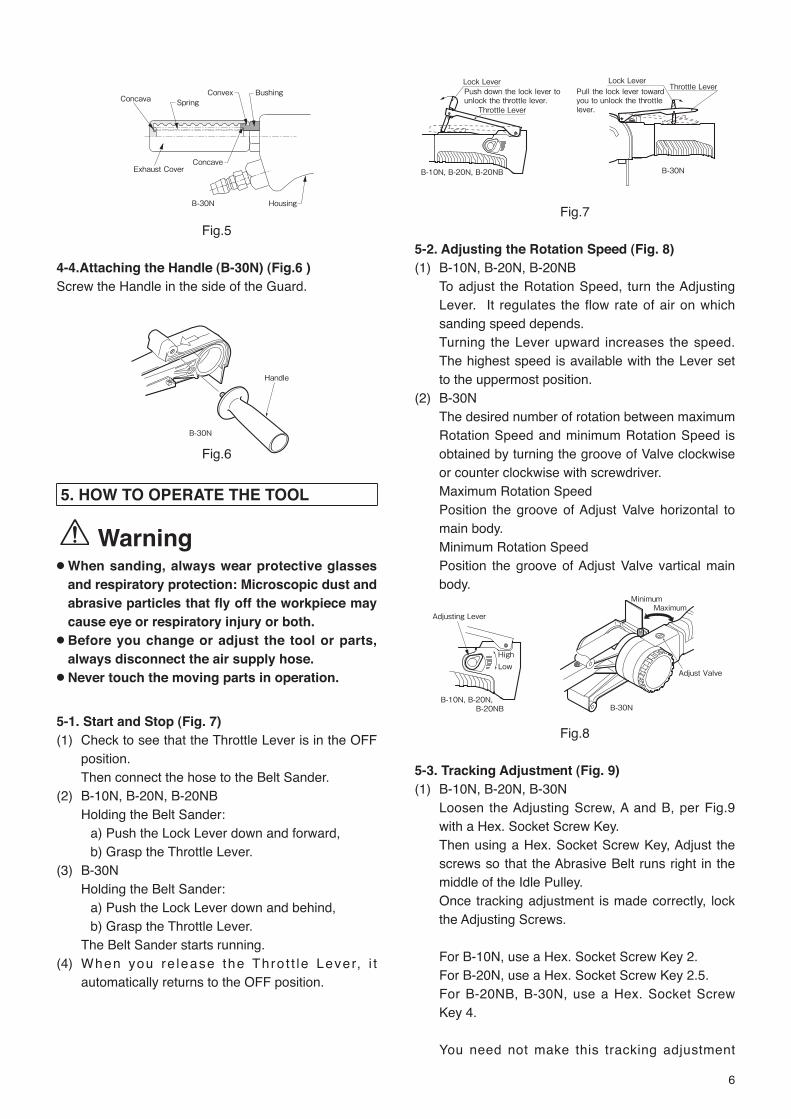
4-3. How To Fix Silencer (B-30N) (Fig.5)(a) Insert the Spring into the Exhaust Cover. (b) Insert the Spring into the concave of the Bushing
PF3/8 of the Belt Sander. (c) Insert the convex of the Exhaust Cover into the
groove of the Bushing PF3/8.
Guard B-30N
Housing
A
Carefully fasten the Guard so that there is no clearance between the Housing and the Guard.
6
Concava Spring Convex Bushing
Exhaust Cover Concave
Housing
B-30N
Fig.5
4-4.Attaching the Handle (B-30N) (Fig.6 )Screw the Handle in the side of the Guard.
Handle
B-30N
Fig.6
5. HOW TO OPERATE THE TOOL
Warning● When sanding, always wear protective glasses
and respiratory protection: Microscopic dust and abrasive particles that fly off the workpiece may cause eye or respiratory injury or both.
● Before you change or adjust the tool or parts, always disconnect the air supply hose.
● Never touch the moving parts in operation.
5-1. Start and Stop (Fig. 7)(1) Check to see that the Throttle Lever is in the OFF
position. Then connect the hose to the Belt Sander.
(2) B-10N, B-20N, B-20NBHolding the Belt Sander:
a) Push the Lock Lever down and forward,b) Grasp the Throttle Lever.
(3) B-30NHolding the Belt Sander:
a) Push the Lock Lever down and behind,b) Grasp the Throttle Lever.
The Belt Sander starts running.(4) When you re lease the Thro t t le Lever, i t
automatically returns to the OFF position.
Push down the lock lever tounlock the throttle lever.
Lock Lever
Throttle Lever
B-10N, B-20N, B-20NB
Fig.7
5-2. Adjusting the Rotation Speed (Fig. 8)(1) B-10N, B-20N, B-20NB
To adjust the Rotation Speed, turn the Adjusting Lever. It regulates the flow rate of air on which sanding speed depends.Turning the Lever upward increases the speed. The highest speed is available with the Lever set to the uppermost position.
(2) B-30NThe desired number of rotation between maximum Rotation Speed and minimum Rotation Speed is obtained by turning the groove of Valve clockwise or counter clockwise with screwdriver.Maximum Rotation SpeedPosition the groove of Adjust Valve horizontal to main body.Minimum Rotation SpeedPosition the groove of Adjust Valve vartical main body.
Low
Adjusting Lever
High
B-10N, B-20N, B-20NB
Adjust Valve
MinimumMaximum
B-30N
Fig.8
5-3. Tracking Adjustment (Fig. 9)(1) B-10N, B-20N, B-30N
Loosen the Adjusting Screw, A and B, per Fig.9 with a Hex. Socket Screw Key.Then using a Hex. Socket Screw Key, Adjust the screws so that the Abrasive Belt runs right in the middle of the Idle Pulley.Once tracking adjustment is made correctly, lock the Adjusting Screws.
For B-10N, use a Hex. Socket Screw Key 2.For B-20N, use a Hex. Socket Screw Key 2.5.For B-20NB, B-30N, use a Hex. Socket Screw Key 4.
You need not make this tracking adjustment
Throttle Lever Lock Lever
B-30N
Pull the lock lever toward you to unlock the throttle lever.

7
when you have an optional 6 mm wide Bracket 6 Assembly (applicable to B-10N only).
(2) B-20NBLoosen the Hex. Cap Screw, Fig.9 with a Hex. Socket Screw Key.Turn the Hex. Socket Head Cap Screw clockwise or counterclockwise with the accessory Hex. Socket Screw Key in order to make the abrasive belt run on the center of the idle pulley.
Loosen Adjusting Screw B
Adjusting Screw B
Adjusting Screw A
Loosen Adjusting Screw A
B-10N, B-20N, B-30N
Belt movementwhen turnedclockwise
Hex. Socket Head Cap Screw
Belt movementwhen turnedcounterclockwise
Clockwise turn
Counterclockwise turn B-20NB
Fig.9
5-4. Sanding Operation
Warning● Do not press the Abrasive Belt too hard upon the
workpiece. If you do so, the Abrasive Belt may break.
● When using a non-woven Belt, do not use the Offset Bracket. If you do so, the Belt may come Off , causing personal injury.
For deburring operation, an Offset Bracket (optional) is to be used. In this application, the Abrasive Belt will be brought into light contact with the workpiece somewhere in between the Idle Pulley and Offset Bracket.
For Sanding operation, the Offset Bracket will be removed and a Shoe will be used.The Abrasive Belt will be brought into light contact with the workpiece where the Shoe extends.
5-5. Changing the Abrasive Belt
Caution● Before servicing, turn the Throttle Lever OFF
and disconnect the hose from the Belt Sander.● When the Abrasive Belt has an arrow marking on
its inner face, see to it that you set it to the same direction in which the Belt Sander turns (there is a marking on the Guard), as well. It is dangerous to mount it wrong way for the Abrasive Belt may break prematurely.
● Do not press the Push Button without a Abrasive Belt mounted unless it is absolutely necessary
to do so, for it may cause equipment failure. ● When changing the Abrasive Belt, remove dust
and abrasive particles from the Drive Pulley area by air blow, etc.
a) B-10N, B-20N, B-20NB (Fig.10)1) Loosen the Decorative Screw and turn the Belt
Cover.2) Keep pushing the Idle Pulley until the Tension
Bar locks. 3) Change the Abrasive Belt with a new one.
Press the Push Button to release Tension Bar locking.
4) Turn the Belt Cover to get it back to where it was. Tighten the Decorative Screw.
Belt Cover
Idle Pulley
Push the Idle Pulley in the direction of arrow
Push Button
Decorative Screw
B-10N, B-20N, B-20NB
Fig.10
b) B-30N (Fig.11)1) Loosen the Decorative Screw and turn the Belt
Cover.2) Keep pushing the Idle Pulley until the Tension
Bar locks.3) Change the Abrasive Belt with a new one.
Press the Shoe to release Tension Bar locking.4) Turn the Belt Cover to get it back to where it
was. Tighten the Decorative Screw.
Decorative Screw
Shoe
Push the Shoe in the direction of arrow
Put the Idle Pulley in the direction of arrow
Belt Cover
Idle Pulley Rotation
B-30N
Fig.11
5-6. Offset Bracket (Optional)The Offset Bracket is designed to utilize the spring action of Abrasive Belt, facilitating light-duty sanding applications, such as contoured surface sanding, deburring, etc.a) B-10N, B-20N, B-20NB (Fig.12)
You do not need tools for mounting or removal of the Offset Bracket.1) Following the same procedure as Abrasive Belt
replacement, remove the Abrasive Belt.
8
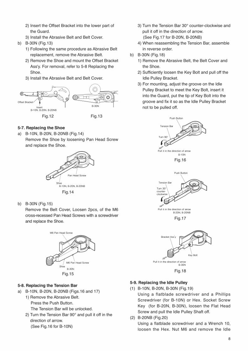
2) Insert the Offset Bracket into the lower part of the Guard.
3) Install the Abrasive Belt and Belt Cover. b) B-30N (Fig.13)
1) Following the same procedure as Abrasive Belt replacement, remove the Abrasive Belt.
2) Remove the Shoe and mount the Offset Bracket Ass'y. For removal, refer to 5-8 Replacing the Shoe.
3) Install the Abrasive Belt and Belt Cover.
Insert
Offset Bracket
B-10N, B-20N, B-20NB
Fig.12 Fig.13
5-7. Replacing the Shoea) B-10N, B-20N, B-20NB (Fig.14)
Remove the Shoe by loosening Pan Head Screw and replace the Shoe.
Pan Head Screw
Shoe B-10N, B-20N, B-20NB
Fig.14
b) B-30N (Fig.15)Remove the Belt Cover, Loosen 2pcs, of the M6 cross-recessed Pan Head Screws with a screwdriver and replace the Shoe.
M6 Pan Head Screw Shoe
M6 Pan Head Screw
B-30N
Fig.15
5-8. Replacing the Tension Bara) B-10N, B-20N, B-20NB (Figs.16 and 17)
1) Remove the Abrasive Belt.Press the Push Button.The Tension Bar will be unlocked.
2) Turn the Tension Bar 90° and pull it off in the direction of arrow.(See Fig.16 for B-10N)
3) Turn the Tension Bar 30° counter-clockwise and pull it off in the direction of arrow.(See Fig.17 for B-20N, B-20NB)
4) When reassembling the Tension Bar, assemble in reverse order.
b) B-30N (Fig.18)1) Remove the Abrasive Belt, the Belt Cover and
the Shoe.2) Sufficiently loosen the Key Bolt and pull off the
Idle Pulley Bracket.3) For mounting, adjust the groove on the Idle
Pulley Bracket to meet the Key Bolt, insert it into the Guard, put the tip of Key Bolt into the groove and fix it so as the Idle Pulley Bracket not to be pulled off.
Pull it in the direction of arrow
Turn 90°
Tension Bar
Push Button
B-10N
Fig.16
Pull it in the direction of arrow
Turn 30° counter- clockwise
Tension Bar
Push Button
B-20N, B-20NB
Fig.17
Pull it in the direction of arrow
Bracket Ass’y
Key Bolt
B-30N
Fig.18
5-9. Replacing the Idle Pulley(1) B-10N, B-20N, B-30N (Fig.19)
Using a flatblade screwdriver and a Phillips Screwdriver (for B-10N) or Hex. Socket Screw Key (for B-20N, B-30N), loosen the Flat Head Screw and pull the Idle Pulley Shaft off.
(2) B-20NB (Fig.20)Using a flatblade screwdriver and a Wrench 10, loosen the Hex. Nut M6 and remove the Idle
B-30N

9
Pulley B Ass’y. When mounting the Idle Pulley B Ass’y, assenble in reverse order.
Flat Head Screw
or
Idle Pulley
B-10N, B-20N, B-30N
Loosen Wrench
Screwdriver
Use a spacer here.
Tighten
B-20NB
Fig.19 Fig.20
6. THREAD SIZE OF HOSE FITTINGThe product comes with a metal fitting with R(metric) thread. Connect the Bushing R thread × NPT thread in the vinyl bag containing standard accessories, if you would like to have American NPT thread instead.
7. STORAGE
Caution● When tool is not used, store it out of reach of
children.
Avoid storing the tool in a location subject to high
humidity. If the tool is left as it is used, residual
moisture on the inside can cause rusting. Before
storing, and after operation, oil the tool at the air inlet
with machine oil ISO VG-10 and run it for a short time.
8. OPTIONAL PARTSIn addition to various kinds or grain sizes of abrasive materials and Sanding Belts, we have the following optional items to meet your diversified needs.
(1) Bracket 6 Ass’y (TB07283) for B-10N ….. for use with our narrow belt 6 mm in width, best suited for corner grinding or grinding in a narrow space. (Fig. 21)For mounting and removal, see 5-9 Replacing the Tension Bar.
(2) Offset Bracket AssemblyOffset Bracket 10 Ass’y (TB05539) for B-10NOffset Bracket 20 Ass’y (TB07109) for B-20N, B-20NBOffset Bracket 30 Ass’y (TB08150) for B-30N
Shoe 6 (TQ10942)
Bracket 6 Ass’y (TB07283)
Fig.21
9. ORDERING SERVICE PARTSFor further operational and handling information or for replacement of parts and components, contact the company from whom you purchased the tool or an authorized dealer.In ordering parts and components give each part number, part name and quantity required.Use only NITTO genuine parts.

10
10. EXPLODED DIAGRAM: B-10N
WarningThis diagram is for your reference only. Do not attempt to service or repair the Tool. Do not take the Tool apart. Contact an authorized Nitto dealer for all service and repair of the Tool. Improper service and repair can cause accidents and severe injuries.Never attempt to modify the Tool.Never attempt service or repair the Tool yourself.
The parts numbers with ( ) are included in the Ass'y parts written above them.No. Part No. Description Qty Price
1 TB08236 Bracket 10 Ass'y 1set2 (TA99155) Idle Pulley10 Sub Ass'y 1set3 (TQ12264) Idle Pulley Shaft10 14 (TP14455) Countersunk Head Screw 2X5 1
5 (TQ10725) Hex. Socket Countersunk Head Screw 3X6 2
6 (TB07898) Bracket 10 Sub Ass'y 1set7 (TP14798) Spring Pin 3X10 AW 18 (TQ10526) Tension Bar Spring 19 (TB07236) Tension Bar Shaft Ass'y 1set
10 TQ07201 Guard Insert 111 TQ10934 Stopper 112 TQ10724 Spring 1.2X8.4X34 1
13 TP15643 Hex. Socket Set Screw 4X4 with Flat Point 1
14 TQ07218 Spring 0.35X7.5X7 115 TQ10587 Push Button 116 TQ10709 Shoe 10 117 TP02618 Pan Head Screw 4X8 118 TB07294 Guard Sub Ass'y B 1set19 (TP08646) Hex. Socket Head Cap Screw 5X14 120 (TP16361) Label Caution 121 (TQ10710) Dust Cover 122 TQ10711 Belt Cover 10 123 TQ10712 Decorative Screw 124 TP00144 Washer M4 125 TP12819 Pan Head Screw 4X6 126 TP14916 Drive Pulley 127 TP01924 Hex. Nut M6 128 TB08629 Cap Ass'y 1set29 (TQ12644) Label Model B-10N 130 TP05531 O-ring S-36 131 TP06386 Ball Bearing 607ZZ 132 TP12414 End Plate A 133 TP12415 Cylinder 134 TA9A364 Blade Ass'y (4pcs/set) 1set35 TP10130 Parallel Key Both Ends Round 3X3X10 136 TP12416 Rotor 137 TP06322 Spacer 8X11X3 138 TP12418 End Plate B 1
No. Part No. Description Qty Price39 TP12419 Ball Bearing 628ZZ 140 TB08626 Housing Sub Ass'y 1set41 (TQ12650) Label Warning 142 TQ11724 Parallel Pin 3X16 143 TQ11560 Tapping Screw 3X8 344 TB07709 Lever Ass'y 1set45 (TP13893) Spring Pin 3X22AW 146 TQ11554 Adjust Lever 147 TP08598 Pan Head Screw 3X5 148 TQ11626 Lever Cap 149 TQ11555 Packing 150 CQ14480 O-ring JASO-1010 151 TB08078 Air Inlet Sub Ass'y 1set52 TB07938 Throttle Valve Ass'y 1set53 (TP14604) O-ring S-10 154 (TP12569) O-ring S-11.2 255 TB07708 Valve Stem Ass'y 1set56 (TQ10395) O-ringSS-2.5 157 (TP11994) O-ringP-4 158 (TP03769) Valve Spring 159 TB07937 Adjust Valve Ass'y 1set60 (CQ25954) O-ring AS568-012 161 (CQ05860) O-ring AS568-013 162 (CP24969) O-ring JASO-1011 163 TP07031 O-ring S-8 164 TB08079 Silencer Ass'y 1set65 TP00857 Bushing M16XRc1/4 1
Accessories
No. Part No. Description Qty PriceTP01939 Hex. Socket Screw Key 4 1TP13892 Hex. Socket Screw Key 2 1
66
TP16597 Abrasive Belt Z76XN #60X10 2TQ00109 Abrasive Belt Z76XN #80X10 1TQ00110 Abrasive Belt Z76 #100X10 1TQ00352 Abrasive Belt Z76 #120X10 1TP02236 Bushing R1/4XNPT1/4 1TQ12660 Instruction Manual 1TQ12617 Declaration of Conformity 1
46
26
2 4
5
1
6 78
9
1011
12
13
17
16
1514
66
3
27
4243
44
49
50
51 60
59
181920
21
22
24
25
23
62
4365
4363
64
5857
5654
53
52
45
40 41
3938
3736
35
34
2928
3231
30
33
4748
61
55

11
11. EXPLODED DIAGRAM: B-20N
WarningThis diagram is for your reference only. Do not attempt to service or repair the Tool. Do not take the Tool apart. Contact an authorized Nitto dealer for all service and repair of the Tool. Improper service and repair can cause accidents and severe injuries.Never attempt to modify the Tool.Never attempt service or repair the Tool yourself.
No. Part No. Description Qty Price43 TB08627 Housing Sub Ass'y 1set44 (TQ12650) Label Warning 145 TQ11724 Parallel Pin 3X16 146 TQ11560 Tapping Screw 3X8 347 TB07709 Lever Ass'y 1set48 (TP13893) Spring Pin 3X22AW 149 TQ11554 Adjust Lever 150 TP08598 Pan Head Screw3X5 151 TQ11626 Lever Cap 152 TQ11555 Packing 153 CQ14480 O-ring JASO-1010 154 TQ11551 Air Inlet 155 TB07938 Throttle Valve Ass'y 1set56 (TP14604) O-ring S-10 157 (TP12569) O-ring S-11.2 258 TB07708 Valve Stem Ass'y 1set59 (TQ10395) O-ring SS-2.5 160 (TP11994) O-ring P-4 161 (TP03769) Valve Spring 162 TB07937 Adjust Valve Ass'y 1set63 (CQ25954) O-ring AS568-012 164 (CQ05860) O-ring AS568-013 165 (CP24969) O-ring JASO-1011 166 TP07031 O-ring S-8 167 TQ11558 Silencer 168 TP00857 Bushing M16XRc1/4 1
Accessories
No. Part No. Description Qty Price
69
TP15867 Abrasive Belt Z76X #60X20 2TP15868 Abrasive Belt Z76X #80X20 1TP15869 Abrasive Belt Z76X #100X20 1TP15870 Abrasive Belt Z76X #120X20 1
70 TB07908 Finger Pad Sub Ass'y 1set71 (TP00051) Pan Head Screw 5X10 172 (TP02419) Pan Head Screw 6X10 1
TP04305 Hex. Socket Screw Key 2.5 1TP01939 Hex. Socket Screw Key 4 1TQ11686 Convex Shoe 1TP02236 Bushing R1/4XNPT1/4 1TQ12660 Instruction Manual 1TQ12617 Declaration of Conformity 1
No. Part No. Description Qty Price1 TA99885 Idle Pulley A Sub Ass'y 1set2 TQ11616 Idle Pulley Shaft 13 TP16219 Hex. Countersunk Head Screw 4X10 14 TQ11400 Hex. Socket Button Head Screw4X8 25 TQ12197 Toothed Lock Washer AW-4 26 TB07747 Bracket Sub Ass'y A 1set7 TP03544 Spring Pin3X16 AW 18 TQ10526 Tension Bar Spring 19 TB07777 Tension Bar Shaft Ass'y 1set
10 TQ11610 Stopper 111 TQ11609 Guard Insert 112 TQ11620 Push Rod 113 TQ11621 Spring1.6X11X45 1
14 TQ12196 Hex. Socket Set Screw 4X5 with Cup Point 1
15 TQ11659 Hex. Socket Button Head Screw 3X6 116 TQ11611 Shoe 117 TQ11660 Pan Head Screw 5X6 118 TQ10712 Decorative Screw 119 TQ07218 Spring 0.35X7.5X7 120 TQ11622 Push Button 121 TB08068 Guard Sub Ass'y B 1set22 (TP04532) Hex. Socket Head Cap Screw 5X30 123 (TP16361) Label Caution 124 (TP16360) Label Rotation 125 (TP16207) Dust Cover 126 TQ11618 Belt Cover 127 TP00144 Washer M4 128 TP12819 Pan Head Screw4X6 129 TQ11617 Drive Pulley 130 TP01918 Hex. Nut M10 131 TB08630 Cap Ass'y 1set32 (TQ12645) Label Model B-20N 133 CQ04413 O-ring S-38 134 TP00468 Ball Bearing 608ZZ 135 TP01907 End Plate A 136 TP10000 Cylinder 137 TA9A212 Blade Ass'y(4pcs/set) 1set
38 TP00502 Parallel Key Both Ends Round 4X4X9.5 1
39 TP01909 Rotor 140 TP01912 Spacer 141 TP01911 End Plate B 142 TP01913 Ball Bearing 6000ZZ 1
987
645
2
69
1011
12
1
313
1617
20
29
2827
26
30
1918
14
15
2223
21
25
70
71
7249
4546
47
52
53
54 63
62 65
4668
4666
67
61
60
59
57
56
55
48
43 44
4241
4039
38
37
3231
3534
33
36
5051
64
58
24
The parts numbers with ( ) are included in the Ass'y parts written above them.

12
12. EXPLODED DIAGRAM: B-20NB
WarningThis diagram is for your reference only. Do not attempt to service or repair the Tool. Do not take the Tool apart. Contact an authorized Nitto dealer for all service and repair of the Tool. Improper service and repair can cause accidents and severe injuries.Never attempt to modify the Tool.Never attempt service or repair the Tool yourself.
No. Part No. Description Qty Price46 TQ11560 Tapping Screw 3X8 347 TB07709 Lever Ass'y 1set48 (TP13893) Spring Pin 3X22AW 149 TQ11554 Adjust Lever 150 TP08598 Pan Head Screw3X5 151 TQ11626 Lever Cap 152 TQ11555 Packing 153 CQ14480 O-ring JASO-1010 154 TQ11551 Air Inlet 155 TB07938 Throttle Valve Ass'y 1set56 (TP14604) O-ring S-10 157 (TP12569) O-ring S-11.2 258 TB07708 Valve Stem Ass'y 1set59 (TQ10395) O-ring SS-2.5 160 (TP11994) O-ring P-4 161 (TP03769) Valve Spring 162 TB07937 Adjust Valve Ass'y 1set63 (CQ25954) O-ring AS568-012 164 (CQ05860) O-ring AS568-013 165 (CP24969) O-ring JASO-1011 166 TP07031 O-ring S-8 167 TQ11558 Silencer 168 TP00857 Bushing M16XRc1/4 1
Accessories
No. Part No. Description Qty Price
69
TP15867 Abrasive Belt Z76X #60X20 2TP15868 Abrasive Belt Z76X #80X20 1TP15869 Abrasive Belt Z76X #100X20 1TP15870 Abrasive Belt Z76X #120X20 1
70 TB07908 Finger Pad Sub Ass'y 1set71 (TP00051) Pan Head Screw 5X10 172 (TP02419) Pan Head Screw 6X10 1
TP01939 Hex. Socket Screw Key 4 1TQ11686 Convex Shoe 1TP02236 Bushing R1/4XNPT1/4 1TQ12660 Instruction Manual 1TQ12617 Declaration of Conformity 1
No. Part No. Description Qty Price73 TB08336 Idle Pulley Bracket Sub Ass'y 1set74 TA90514 Idle Pulley B Ass'y 1set10 TQ11610 Stopper 111 TQ11609 Guard Insert 112 TQ11620 Push Rod 113 TQ11621 Spring1.6X11X45 1
14 TQ12196 Hex. Socket Set Screw 4X5 with Cup Point 1
15 TQ11659 Hex. Socket Button Head Screw 3X6 116 TQ12411 Shoe 117 TQ11660 Pan Head Screw 5X6 118 TQ10712 Decorative Screw 119 TQ07218 Spring 0.35X7.5X7 120 TQ11622 Push Button 121 TB08068 Guard Sub Ass'y B 1set22 (TP04532) Hex. Socket Head Cap Screw 5X30 123 (TP16361) Label Caution 124 (TP16360) Label Rotation 125 (TP16207) Dust Cover 126 TQ11618 Belt Cover 127 TP00144 Washer M4 128 TP12819 Pan Head Screw4X6 129 TQ11617 Drive Pulley 130 TP01918 Hex. Nut M10 131 TB08579 Cap Ass'y 1set32 (TQ12604) Label Model B-20NB 133 CQ04413 O-ring S-38 134 TP00468 Ball Bearing 608ZZ 135 TP01907 End Plate A 136 TP10000 Cylinder 137 TA9A212 Blade Ass'y(4pcs/set) 1set
38 TP00502 Parallel Key Both Ends Round 4X4X9.5 1
39 TP01909 Rotor 140 TP01912 Spacer 141 TP01911 End Plate B 142 TP01913 Ball Bearing 6000ZZ 143 TB08627 Housing Sub Ass'y 1set44 (TQ12650) Label Warning 145 TQ11724 Parallel Pin 3X16 1
69
10 11
12
13
16 17
20
29
2827
26
30
19 18
14
15
22 23
21
25
70
71
72 49
45 46
47
52
53
54 63
62 65
46 68
46 66
67
61
60
59
57
56
55
48
43 44
42 41
40 39
38
37
32 31
35 34
33
36
50 51
64
58
24
73
74
The parts numbers with ( ) are included in the Ass'y parts written above them.

13
13. EXPLODED DIAGRAM: B-30N
WarningThis diagram is for your reference only. Do not attempt to service or repair the Tool. Do not take the Tool apart. Contact an authorized Nitto dealer for all service and repair of the Tool. Improper service and repair can cause accidents and severe injuries.Never attempt to modify the Tool.Never attempt service or repair the Tool yourself.
30
31 29
33
1
2
5
6
7
8 3
9
10
11 12
13
15
17 16
18 19 20
21 18
22
23 24
25 26
27
28
32
34
35 37
36 38
39 40
41
42
43
46
44 45
47
48
49
50
51
52
53
54
55
57
34
4
14
No. Part No. Description Qty Price1 TB08170 Idle Pulley A Ass'y 1set2 TQ11792 Idle Pulley Shaft 13 TP16219 Hex. Countersunk Head Screw 4X10 14 TB08028 Bracket Sub Ass'y 1set5 TP07577 Spring Pin 4X16 AW 16 TP08646 Hex.Cap Screw 5X14 27 TQ12215 Toothed Lock Washer AW-5 28 TQ10526 Tension Bar Spring 19 TQ11793 Tension Bar 1
10 TQ11881 Flat Shoe 111 TQ11794 Spring1.4X7.2X110 112 TQ11838 Spring Guide 113 TB08171 Guard Sub Ass'y B 1set14 (TP16360) Label Rotation 115 (TP16361) Label Caution 116 (TP04060) Dust Cover 117 (TP04073) Hex.Cap Screw 6X35 118 TP08132 Pan Head Screw 6X8 219 TA92254 Key Bolt Ass'y 1set20 TQ11810 Shoe Spring 121 TQ11997 Parallel Pin 5X16 122 TQ02418 Decorative Screw 5X10 123 TQ11797 Belt Cover 124 TQ04426 Nylon Washer 125 TP04077 Hex.Nut M12X1.5 126 TQ11807 Drive Pulley 1set27 TP04058 Thrust Washer B 36.2X62X1 128 TP06290 Pan Head Screw 4X 8 129 TB01793 Throttle Lever Ass'y 1set30 (TP00460) Spring Pin 3X22 AW 131 (TP05498) Spring Pin 2X16 AW 132 TB08628 Housing Sub Ass'y 1set33 (TQ12656) Label Warning 134 TP00498 Ball Bearing 6001ZZ 2
No. Part No. Description Qty Price35 TQ11986 Hex. Countersunk Head Screw 4X8 236 TP04061 SpringPin 3X 6 AW 137 TQ11801 Lower Bearing Case 138 TP04036 Spacer 139 TP04032 Rotor 140 TP00502 Parallel Key Both Ends Round 4X4X9.5 141 TA9A215 Blade Ass'y (5pcs/set) 1set42 TP04031 Cylinder 143 TP04035 Upper Bearing Case 144 TB08631 Cap Ass'y 1set45 (TQ12646) Label Model 146 TQ11806 O-Ring AS568A-034 147 TA93925 Valve Stem Ass'y 1set48 TP12405 Adjust Valve 149 TP12407 O-Ring S- 15 150 TP12406 Spacer 10.5X17.9X1.6 151 CP00987 Internal Retaining Ring C- 18 152 TP10005 Bushing PF 3/8 153 TA96323 Silencer Ass'y 1set54 TP00857 Bushing M16XRc1/4 1
Accessories
No. Part No. Description Qty Price55 TB08248 Handle Ass'y 1set
TP01939 Hex. Socket Screw Key 4 1
57
TQ00358 Abrasive Belt Z76X # 60X30 2TQ00359 Abrasive Belt Z76X # 80X30 1TQ00360 Abrasive Belt Z76X #100X30 1TP02236 Bushing R1/4XNPT1/4 1TP04004 Hex. Socket Screw Key 5 1TQ12660 Instruction Manual 1
TQ12617 Declaration of Conformity 1
The parts numbers with ( ) are included in the Ass'y parts written above them.

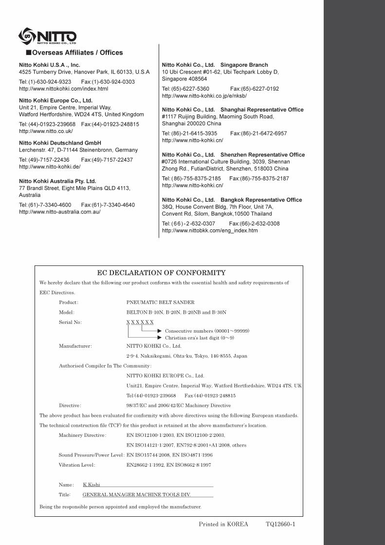
�Overseas Affiliates / Offices
Nitto Kohki U.S.A ., Inc.
4525 Turnberry Drive, Hanover Park, IL 60133, U.S.A
Tel: (1)-630-924-9323 Fax:(1)-630-924-0303
http://www.nittokohki.com/index.html
Nitto Kohki Europe Co., Ltd.
Unit 21, Empire Centre, Imperial Way,
Watford Hertfordshire, WD24 4TS, United Kingdom
Tel: (44)-01923-239668 Fax:(44)-01923-248815
http://www.nitto.co.uk/
Nitto Kohki Deutschland GmbH
Lerchenstr. 47, D-71144 Steinenbronn, Germany
Tel: (49)-7157-22436 Fax:(49)-7157-22437
http://www.nitto-kohki.de/
Nitto Kohki Australia Pty. Ltd.
77 Brandl Street, Eight Mile Plains QLD 4113,
Australia
Tel: (61)-7-3340-4600 Fax:(61)-7-3340-4640
http://www.nitto-australia.com.au/
Nitto Kohki Co., Ltd. Singapore Branch
10 Ubi Crescent #01-62, Ubi Techpark Lobby D,
Singapore 408564
Tel: (65)-6227-5360 Fax:(65)-6227-0192
http://www.nitto-kohki.co.jp/e/nksb/
Nitto Kohki Co., Ltd. Shanghai Representative Office
#1117 Ruijing Building, Maoming South Road,
Shanghai 200020 China
Tel: (86)-21-6415-3935 Fax:(86)-21-6472-6957
http://www.nitto-kohki.cn/
Nitto Kohki Co., Ltd. Shenzhen Representative Office
#0726 International Culture Building, 3039, Shennan
Zhong Rd., FutianDistrict, Shenzhen, 518003 China
Tel: (86)-755-8375-2185 Fax:(86)-755-8375-2187
http://www.nitto-kohki.cn/
Nitto Kohki Co., Ltd. Bangkok Representative Office
38Q, House Convent Bldg, 7th Floor, Unit 7A,
Convent Rd, Silom, Bangkok,10500 Thailand
Tel: (66) -2 -632-0307 Fax:(66)-2-632-0308
http://www.nittobkk.com/eng_index.htm
EC DECLARATION OF CONFORMITY
We hereby declare that the following our product conforms with the essential health and safety requirements of
EEC Directives.
Product� PNEUMATIC BELT SANDER
Model� BELTON:B-10N, B-20N, B-20NB and B-30N
Serial No� X X X X X X
Consecutive numbers (00001�99999)
Christian era’s last digit (0�9)
Manufacturer� NITTO KOHKI Co., Ltd.
2-9-4, Nakaikegami, Ohta-ku, Tokyo, 146-8555, Japan
Authorised Compiler In The Community�
NITTO KOHKI EUROPE Co., Ltd.
Unit21, Empire Centre, Imperial Way, Watford Hertfordshire, WD24 4TS, UK
Tel:(44)-01923-239668 Fax:(44)-01923-248815
Directive� 98/37/EC and 2006/42/EC Machinery Directive
The above product has been evaluated for conformity with above directives using the following European standards.
The technical construction file (TCF) for this product is retained at the above manufacturer’s location.
Machinery Directive� EN ISO12100-1:2003, EN ISO12100-2:2003,
EN ISO14121-1:2007, EN792-8:2001+A1:2008, others
Sound Pressure/Power Level� EN ISO15744:2008, EN ISO4871:1996
Vibration Level� EN28662-1:1992, EN ISO8662-8:1997
Name� K.Kishi
Title: GENERAL MANAGER MACHINE TOOLS DIV.
Being the responsible person appointed and employed the manufacturer.
� � � � � � � � � � � � � � � � � � � � � � � � �
Printed in KOREA TQ12660-1