Embed Size (px)
Citation preview

Pneumatic Chemical Metering Pump
©Timberline Manufacturing Company, 2013; All Rights Reserved 1/13
Timberline’s Pneumatic Chemical Metering Pump was designed with the well pumper and the chemical man in mind. Each pump has a simple but rugged design that can be repaired in the field within minutes on the tailgate of a pickup truck. Standard features include 316 SST wetted parts, TFE o-rings in both checks, sealed lube system, and a timer/controller that will turn down to 3 strokes per minute. For chemical injection applications where a pneumatic pump is the right choice, the Timberline Pneumatic Chemical Metering Pump is the ideal pump to meet your needs.
Features:
Dual seals and a piston wear guide (2.25" pistons and larger) ensure concentric plunger stroke and longer seal life. The pump will continue to function properly even after the lower seal has failed. By adding a gauge to the lubrication system the lease operator can determine if maintenance on the pump is required. If maintenance is necessary the operator can order parts and schedule the maintenance at his convenience.
Sealed lubrication system – Lubrication changed only when seals are replaced.
Teflon seats in the discharge and suction check bodies give positive sealing.
Springs are engineered for optimum performance and for long life.
Exhaust gas from both the piston housing and the controller can be vented to a safe area.
The bleed screw is designed to accept a hose to allow collection of chemical.
Materials of Construction:
Wetted Parts (Excluding plunger) 316 SST Plunger 17-4PH SST (Optional) 17-4PH SST Ceramic Coated Piston 303 SST Piston Housing 303 SST O-Rings Viton (Optional) Buna Check Seats TFE MPT Body 303 SST MPT-II Body Aluminum Check Ball 316 SST (Optional) Carbide
Pneumatic Chemical Metering Pump
Page 2
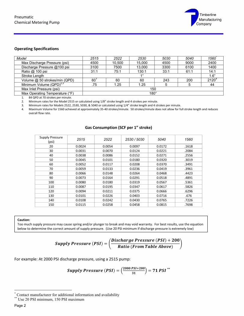
Operating Specifications
Model 2515 2522 2530 5030 5040 1560*
Max Discharge Pressure (psi) 4500 10,500 15,000 4500 9000 2400
Discharge Pressure @100 psi 3100 7500 13,000 3300 6100 1400
Ratio @ 100 psi 31:1 75:1 130:1 33:1 61:1 14:1
Stroke Length 1” 1.6”
Volume @ 50 strokes/min (QPD) 601 60 60 243 200 2120
4
Minimum Volume (QPD)2,3
.75 1.25 1.25 5 5 44
Max Inlet Pressure (psi) 150
Max Operating Temperature (°F) 180° 1. 84 QPD at 70 strokes per minute. 2. Minimum rates for the Model 2515 or calculated using 1/8” stroke length and 4 strokes per minute. 3. Minimum rates for Models 2522, 2530, 5030, & 5040 or calculated using 1/4” stroke length and 4 strokes per minute. 4. Maximum Volume for 1560 achieved at approximately 35-40 strokes/minute. 50 strokes/minute does not allow for full stroke length and reduces
overall flow rate.
Gas Consumption (SCF per 1” stroke)
Supply Pressure (psi)
2515 2522 2530 / 5030 5040 1560
20 0.0024 0.0054 0.0097 0.0172 .1618 30 0.0031 0.0070 0.0124 0.0221 .2084
40 0.0038 0.0086 0.0152 0.0271 .2556
50 0.0045 0.0101 0.0180 0.0320 .3019 60 0.0052 0.0117 0.0208 0.0370 .3491
70 0.0059 0.0133 0.0236 0.0419 .3961
80 0.0066 0.0148 0.0264 0.0468 .4423 90 0.0073 0.0164 0.0291 0.0518 .4891
100 0.0080 0.0180 0.0319 0.0567 .5361 110 0.0087 0.0195 0.0347 0.0617 .5826
120 0.0094 0.0211 0.0375 0.0666 .6296
130 0.0101 0.0226 0.0403 0.0716 .676 140 0.0108 0.0242 0.0430 0.0765 .7226
150 0.0115 0.0258 0.0458 0.0815 .7698
( ) ( ( )
( ))
For example: At 2000 PSI discharge pressure, using a 2515 pump:
( ) (
) **
* Contact manufacturer for additional information and availability
** Use 20 PSI minimum, 150 PSI maximum
Caution: Too much supply pressure may cause spring and/or plunger to break and may void warranty. For best results, use the equation below to determine the correct amount of supply pressure. (Use 20 PSI minimum if discharge pressure is extremely low)
Page 3
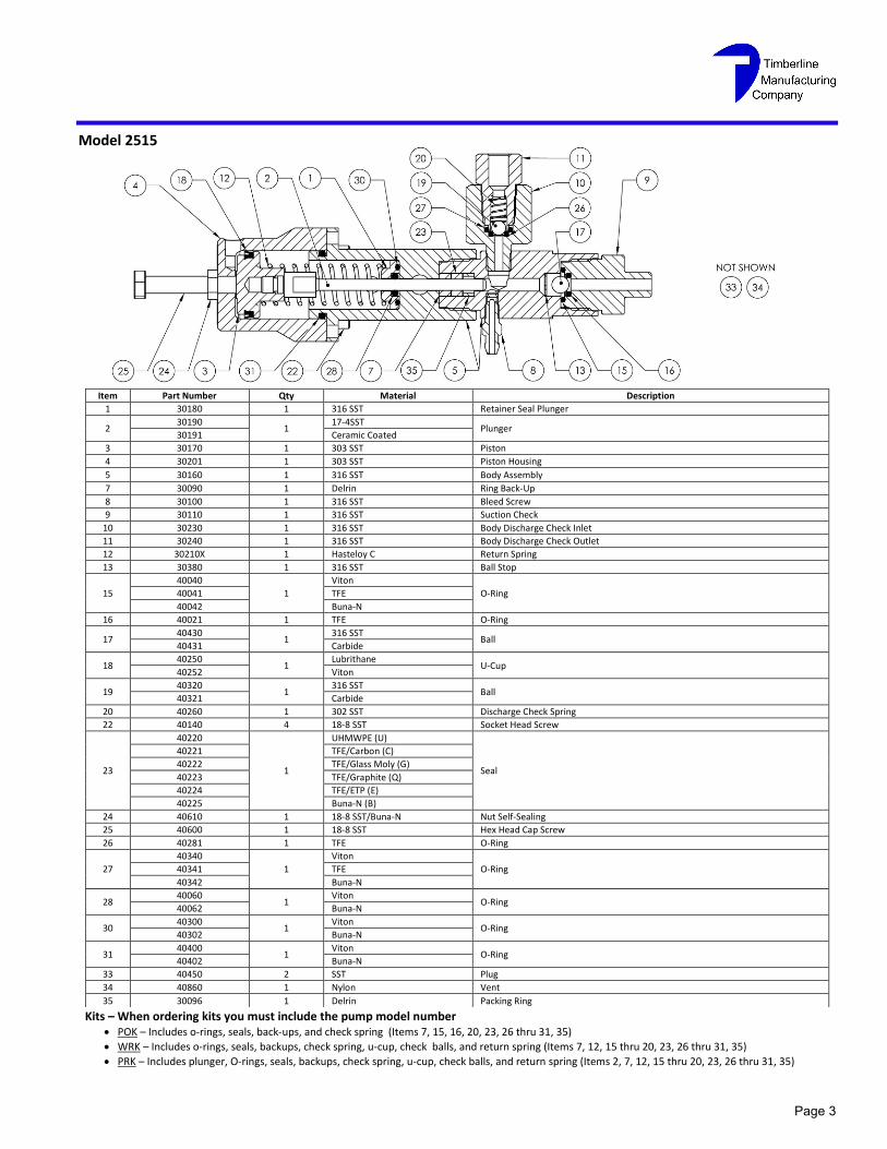
Model 2515
Kits – When ordering kits you must include the pump model number POK – Includes o-rings, seals, back-ups, and check spring (Items 7, 15, 16, 20, 23, 26 thru 31, 35)
WRK – Includes o-rings, seals, backups, check spring, u-cup, check balls, and return spring (Items 7, 12, 15 thru 20, 23, 26 thru 31, 35)
PRK – Includes plunger, O-rings, seals, backups, check spring, u-cup, check balls, and return spring (Items 2, 7, 12, 15 thru 20, 23, 26 thru 31, 35)
Item Part Number Qty Material Description
1 30180 1 316 SST Retainer Seal Plunger
2 30190
1 17-4SST
Plunger 30191 Ceramic Coated
3 30170 1 303 SST Piston
4 30201 1 303 SST Piston Housing
5 30160 1 316 SST Body Assembly
7 30090 1 Delrin Ring Back-Up
8 30100 1 316 SST Bleed Screw
9 30110 1 316 SST Suction Check
10 30230 1 316 SST Body Discharge Check Inlet
11 30240 1 316 SST Body Discharge Check Outlet
12 30210X 1 Hasteloy C Return Spring
13 30380 1 316 SST Ball Stop
15
40040
1
Viton
O-Ring 40041 TFE
40042 Buna-N
16 40021 1 TFE O-Ring
17 40430
1 316 SST
Ball 40431 Carbide
18 40250
1 Lubrithane
U-Cup 40252 Viton
19 40320
1 316 SST
Ball 40321 Carbide
20 40260 1 302 SST Discharge Check Spring
22 40140 4 18-8 SST Socket Head Screw
23
40220
1
UHMWPE (U)
Seal
40221 TFE/Carbon (C)
40222 TFE/Glass Moly (G)
40223 TFE/Graphite (Q)
40224 TFE/ETP (E)
40225 Buna-N (B)
24 40610 1 18-8 SST/Buna-N Nut Self-Sealing
25 40600 1 18-8 SST Hex Head Cap Screw
26 40281 1 TFE O-Ring
27
40340
1
Viton
O-Ring 40341 TFE
40342 Buna-N
28 40060
1 Viton
O-Ring 40062 Buna-N
30 40300
1 Viton
O-Ring 40302 Buna-N
31 40400
1 Viton
O-Ring 40402 Buna-N
33 40450 2 SST Plug
34 40860 1 Nylon Vent
35 30096 1 Delrin Packing Ring
Pneumatic Chemical Metering Pump
Page 4
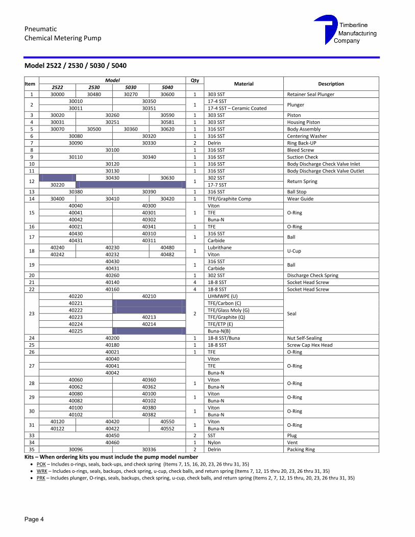
Model 2522 / 2530 / 5030 / 5040
Kits – When ordering kits you must include the pump model number POK – Includes o-rings, seals, back-ups, and check spring (Items 7, 15, 16, 20, 23, 26 thru 31, 35)
WRK – Includes o-rings, seals, backups, check spring, u-cup, check balls, and return spring (Items 7, 12, 15 thru 20, 23, 26 thru 31, 35)
PRK – Includes plunger, O-rings, seals, backups, check spring, u-cup, check balls, and return spring (Items 2, 7, 12, 15 thru, 20, 23, 26 thru 31, 35)
Item Model Qty
Material Description 2522 2530 5030 5040
1 30000 30480 30270 30600 1 303 SST Retainer Seal Plunger
2 30010 30350
1 17-4 SST
Plunger 30011 30351 17-4 SST – Ceramic Coated
3 30020 30260 30590 1 303 SST Piston
4 30031 30251 30581 1 303 SST Housing Piston
5 30070 30500 30360 30620 1 316 SST Body Assembly
6 30080 30320 1 316 SST Centering Washer
7 30090 30330 2 Delrin Ring Back-UP
8 30100 1 316 SST Bleed Screw
9 30110 30340 1 316 SST Suction Check
10 30120 1 316 SST Body Discharge Check Valve Inlet
11 30130 1 316 SST Body Discharge Check Valve Outlet
12 30430 30630
1 302 SST
Return Spring 30220 17-7 SST
13 30380 30390 1 316 SST Ball Stop
14 30400 30410 30420 1 TFE/Graphite Comp Wear Guide
15
40040 40300
1
Viton
O-Ring 40041 40301 TFE
40042 40302 Buna-N
16 40021 40341 1 TFE O-Ring
17 40430 40310
1 316 SST
Ball 40431 40311 Carbide
18 40240 40230 40480
1 Lubrithane
U-Cup 40242 40232 40482 Viton
19 40430
1 316 SST
Ball 40431 Carbide
20 40260 1 302 SST Discharge Check Spring
21 40140 4 18-8 SST Socket Head Screw
22 40160 4 18-8 SST Socket Head Screw
23
40220 40210
2
UHMWPE (U)
Seal
40221 TFE/Carbon (C)
40222 TFE/Glass Moly (G)
40223 40213 TFE/Graphite (Q)
40224 40214 TFE/ETP (E)
40225 Buna-N(B)
24 40200 1 18-8 SST/Buna Nut Self-Sealing
25 40180 1 18-8 SST Screw Cap Hex Head
26 40021 1 TFE O-Ring
27
40040
Viton
O-Ring 40041 TFE
40042 Buna-N
28 40060 40360
1 Viton
O-Ring 40062 40362 Buna-N
29 40080 40100
1 Viton
O-Ring 40082 40102 Buna-N
30 40100 40380
1 Viton
O-Ring 40102 40382 Buna-N
31 40120 40420 40550
1 Viton
O-Ring 40122 40422 40552 Buna-N
33 40450 2 SST Plug
34 40460 1 Nylon Vent
35 30096 30336 2 Delrin Packing Ring
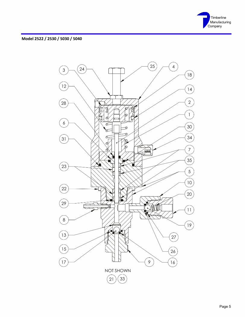
Page 5
Model 2522 / 2530 / 5030 / 5040
Pneumatic Chemical Metering Pump
Page 6
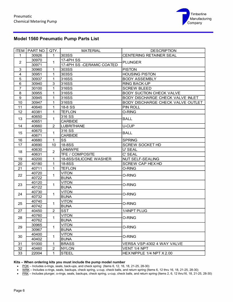
Model 1560 Pneumatic Pump Parts List
ITEM PART NO. QTY. MATERIAL DESCRIPTION
1 30926 1 303SS CENTERING RETAINER SEAL
30970 17-4PH SS
30971 17-4PH SS -CERAMIC COATED
3 30960 1 303SS PISTON
4 30951 1 303SS HOUSING PISTON
5 30937 1 316SS BODY ASSEMBLY
6 30940 3 316SS RING BACK-UP
7 30100 1 316SS SCREW BLEED
8 30955 1 316SS BODY SUCTION CHECK VALVE
9 30945 1 316SS BODY DISCHARGE CHECK VALVE INLET
10 30947 1 316SS BODY DISCHARGE CHECK VALVE OUTLET
11 40640 1 18-8 SS PIN ROLL
12 40381 1 TEFLON O-RING
40650 316 SS
40651 CARBIDE
14 40660 2 LUBRITHANE U-CUP
40670 316 SS
40671 CARBIDE
16 40680 1 SS SPRING
17 40690 10 18-8SS SCREW SOCKET HD
40630 UHMWPE U' SEAL
40631 TFE / COMPOSITE C' SEAL
19 40200 1 18-8SS/SILICONE WASHER NUT SELF-SEALING
20 40180 1 18-8SS SCREW CAP HEX HD
21 40711 1 TEFLON O-RING
40720 VITON
40722 BUNA
40120 VITON
40122 BUNA
40730 VITON
40732 BUNA
40740 VITON
40742 BUNA
27 40450 2 SST 1/4NPT PLUG
40760 VITON
40762 BUNA
30965 VITON
30967 BUNA
40400 VITON
40402 BUNA
31 91000 1 BRASS VERSA VSP-4302 4 WAY VALVE
32 40460 2 NYLON VENT 1/4 NPT
33 22004 1 STEEL HEX NIPPLE 1/4 NPT X 2.00
30
22 1 O-RING
O-RING
O-RING
O-RING
O-RING
O-RING
1
123
24
1
1
29
2 1 PLUNGER
18
15 1 BALL
13 1 BALL
1
2
28
O-RING
125
Kits – When ordering kits you must include the pump model number POK – Includes o-rings, seals, back-ups, and check spring (Items 6, 12, 16, 18, 21-25, 28-30)
WRK – Includes o-rings, seals, backups, check spring, u-cup, check balls, and return spring (Items 6, 12 thru 16, 18, 21-25, 28-30)
PRK – Includes plunger, o-rings, seals, backups, check spring, u-cup, check balls, and return spring (Items 2, 6, 12 thru16, 18, 21-25, 28-30)
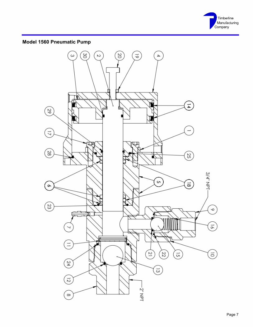
Page 7
Model 1560 Pneumatic Pump

Pneumatic Chemical Metering Pump
Page 8
Model 1560 Pneumatic Pump Supply Connections
Page 9
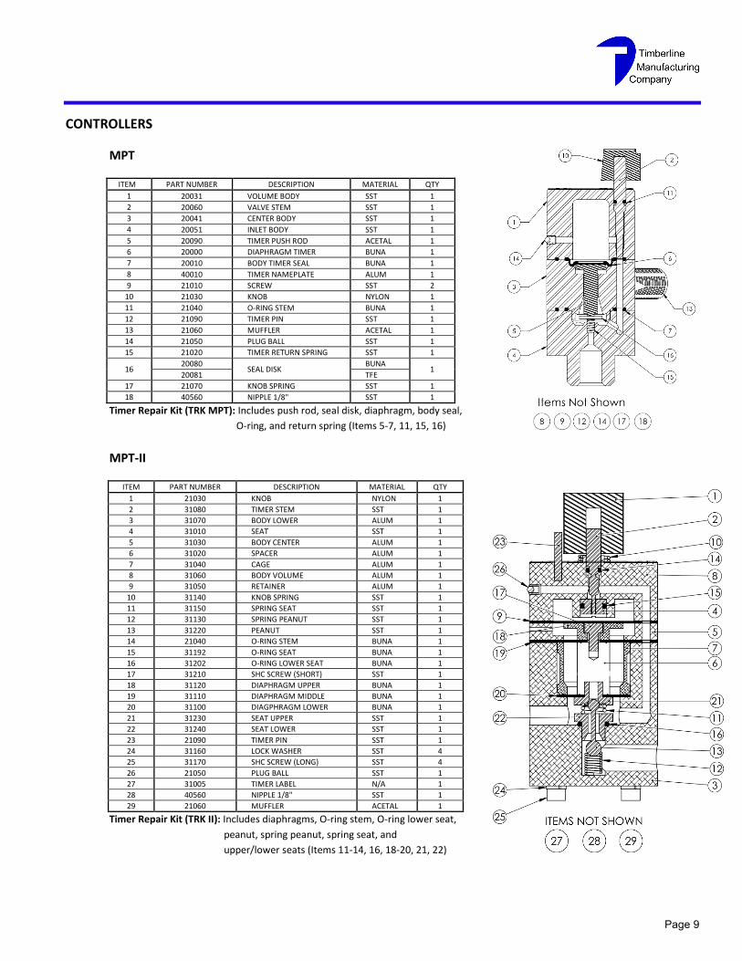
CONTROLLERS
MPT
ITEM PART NUMBER DESCRIPTION MATERIAL QTY
1 20031 VOLUME BODY SST 1
2 20060 VALVE STEM SST 1
3 20041 CENTER BODY SST 1
4 20051 INLET BODY SST 1
5 20090 TIMER PUSH ROD ACETAL 1
6 20000 DIAPHRAGM TIMER BUNA 1
7 20010 BODY TIMER SEAL BUNA 1
8 40010 TIMER NAMEPLATE ALUM 1
9 21010 SCREW SST 2
10 21030 KNOB NYLON 1
11 21040 O-RING STEM BUNA 1
12 21090 TIMER PIN SST 1
13 21060 MUFFLER ACETAL 1
14 21050 PLUG BALL SST 1
15 21020 TIMER RETURN SPRING SST 1
16 20080
SEAL DISK BUNA
1 20081 TFE
17 21070 KNOB SPRING SST 1
18 40560 NIPPLE 1/8" SST 1
Timer Repair Kit (TRK MPT): Includes push rod, seal disk, diaphragm, body seal,
O-ring, and return spring (Items 5-7, 11, 15, 16)
MPT-II
ITEM PART NUMBER DESCRIPTION MATERIAL QTY
1 21030 KNOB NYLON 1
2 31080 TIMER STEM SST 1
3 31070 BODY LOWER ALUM 1
4 31010 SEAT SST 1
5 31030 BODY CENTER ALUM 1
6 31020 SPACER ALUM 1
7 31040 CAGE ALUM 1
8 31060 BODY VOLUME ALUM 1
9 31050 RETAINER ALUM 1
10 31140 KNOB SPRING SST 1
11 31150 SPRING SEAT SST 1
12 31130 SPRING PEANUT SST 1
13 31220 PEANUT SST 1
14 21040 O-RING STEM BUNA 1
15 31192 O-RING SEAT BUNA 1
16 31202 O-RING LOWER SEAT BUNA 1
17 31210 SHC SCREW (SHORT) SST 1
18 31120 DIAPHRAGM UPPER BUNA 1
19 31110 DIAPHRAGM MIDDLE BUNA 1
20 31100 DIAGPHRAGM LOWER BUNA 1
21 31230 SEAT UPPER SST 1
22 31240 SEAT LOWER SST 1
23 21090 TIMER PIN SST 1
24 31160 LOCK WASHER SST 4
25 31170 SHC SCREW (LONG) SST 4
26 21050 PLUG BALL SST 1
27 31005 TIMER LABEL N/A 1
28 40560 NIPPLE 1/8" SST 1
29 21060 MUFFLER ACETAL 1
Timer Repair Kit (TRK II): Includes diaphragms, O-ring stem, O-ring lower seat,
peanut, spring peanut, spring seat, and
upper/lower seats (Items 11-14, 16, 18-20, 21, 22)
Pneumatic Chemical Metering Pump
Page 10
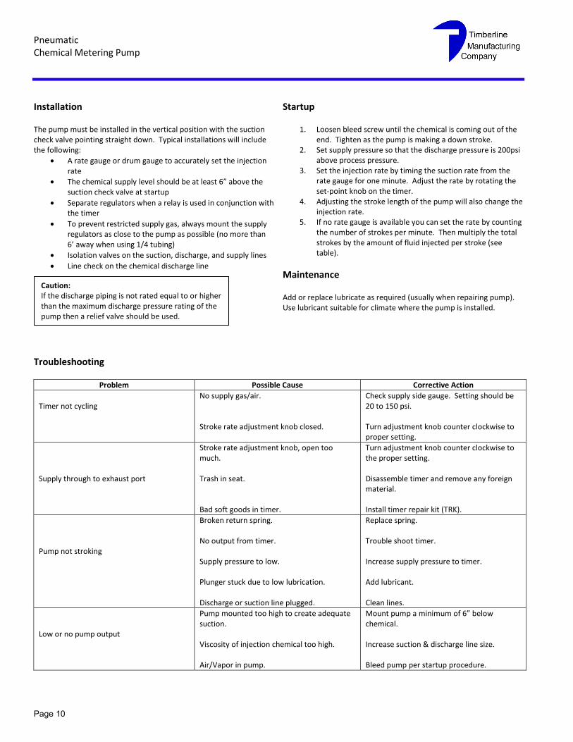
Installation
The pump must be installed in the vertical position with the suction check valve pointing straight down. Typical installations will include the following:
A rate gauge or drum gauge to accurately set the injection rate
The chemical supply level should be at least 6” above the suction check valve at startup
Separate regulators when a relay is used in conjunction with the timer
To prevent restricted supply gas, always mount the supply regulators as close to the pump as possible (no more than 6’ away when using 1/4 tubing)
Isolation valves on the suction, discharge, and supply lines
Line check on the chemical discharge line
Startup
1. Loosen bleed screw until the chemical is coming out of the end. Tighten as the pump is making a down stroke.
2. Set supply pressure so that the discharge pressure is 200psi above process pressure.
3. Set the injection rate by timing the suction rate from the rate gauge for one minute. Adjust the rate by rotating the set-point knob on the timer.
4. Adjusting the stroke length of the pump will also change the injection rate.
5. If no rate gauge is available you can set the rate by counting the number of strokes per minute. Then multiply the total strokes by the amount of fluid injected per stroke (see table).
Maintenance
Add or replace lubricate as required (usually when repairing pump). Use lubricant suitable for climate where the pump is installed.
Troubleshooting
Problem Possible Cause Corrective Action
Timer not cycling
No supply gas/air. Stroke rate adjustment knob closed.
Check supply side gauge. Setting should be 20 to 150 psi. Turn adjustment knob counter clockwise to proper setting.
Supply through to exhaust port
Stroke rate adjustment knob, open too much. Trash in seat. Bad soft goods in timer.
Turn adjustment knob counter clockwise to the proper setting. Disassemble timer and remove any foreign material. Install timer repair kit (TRK).
Pump not stroking
Broken return spring. No output from timer. Supply pressure to low. Plunger stuck due to low lubrication. Discharge or suction line plugged.
Replace spring. Trouble shoot timer. Increase supply pressure to timer. Add lubricant. Clean lines.
Low or no pump output
Pump mounted too high to create adequate suction. Viscosity of injection chemical too high. Air/Vapor in pump.
Mount pump a minimum of 6” below chemical. Increase suction & discharge line size. Bleed pump per startup procedure.
Caution: If the discharge piping is not rated equal to or higher than the maximum discharge pressure rating of the pump then a relief valve should be used.
While this information is presented in good faith and believed to be accurate,
Timberline Manufacturing Company does not guarantee results based upon
such information. Timberline Manufacturing Company reserves the right to
change the design or specifications of these products without notice.
Main Office South Texas Location 3255 Executive Boulevard, Suite 108 115 N. 3
rd Street
Beaumont, Texas 77705 Kenedy, Texas 78119 409-842-0300 Phone 830-583-0531 Phone 409-842-1220 Fax 830-583-0560 Fax www.tlinemfg.com
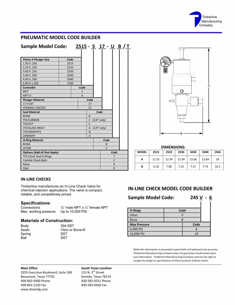
PNEUMATIC MODEL CODE BUILDER
Sample Model Code: 2515 - S 17 - U B / T
Piston X Plunger Size Code
1.50 X .250 2515
2.25 X .250 2522
3.00 X .250 2530
3.00 X .500 5030
4.00 X .500 5040
6.00 X 1.500 1560
Controller Code
MPT S
MPT-II A
Plunger Material Code
17-4 SST 17
CERAMIC COATED CC
Seal Material Code
BUNA B
TFE/CARBON C (1/4” only)
TFE/ETP E
TFE/GLASS MOLY G (1/4” only)
TFE/GRAPHITE Q
UHMWPE U
O-Ring Material Code
BUNA B
VITON V
Options (Add all that Apply) Code
TFE Check Seal O-Rings T
Carbide Check Balls C
Relay R
Oiler O
IN-LINE CHECKS
Timberline manufactures an In-Line Check Valve for chemical injection applications. The valve is compact, reliable, and competitively priced.
Specifications: Connections ¼” male NPT x ¼” female NPT Max. working pressure Up to 10,000 PSI
Materials of Construction: Body 304 SST Seals Viton or Buna-N Spring SST Ball SST
IN-LINE CHECK MODEL CODE BUILDER
Sample Model Code: 24S V - 6
O-Rings Code
Viton V
Buna B
Max Pressure Code
6,000 PSI 6
10,000 PSI 10
DIMENSIONS: MODEL 2515 2522 2530 5030 5040 1560
A 11.55 12.34 12.34 12.66 12.64 18
B 6.18 7.08 7.32 7.27 7.74 16.5