Embed Size (px)
Citation preview

Pneumatic circuits: R, CPressure is potential, pressure difference is voltage dropA flow restrictor is a resistanceAn air chamber is a capacitance
Resistance R P+pc
P+pi q
Q
P
Slope R
C
Cpi
Rpc 1
11 1c i i
sCp p psRCR
sC

Position to Pressure transducer/amplifiers
Ps is pressure of supply air from wall pipe or air cylinderX is weighted differential average of input position and the pivot positionX controls the pressure Pb send to the control valve
bP Kx
Cps
R pb
When C is very small,
xb s a
x x
R Rp p p
R R R R
pa
Rx

Pneumatic proportional controller
Ps is const parameter
Diaphragm is fast, so pc and pb are equal
x is weighted diff sum of e and y
b ax e y
a b a b
Notice the direction of x and e:
c bp p Kx c bellow sp A f k y

Pneumatic proportional controller
Since pc=pb
Drawing for this part can be simplified

Proportional + derivative controller
Recall: bellow pressure is related to input pressure by1/(RCs+1)
Pbellow
( ) ( 1)( ) ( ) ( ) ( 1)
( ) ( 1)s s
cs
K a b k RCs bkbP s E s E s RCs
a b KaA a b k RCs aA

Proportional + Integral controller
11
1
1
RCsRCs
RCs
So, in closed-loop TF, replace (RCs+1) by (RCs+1)/RCs:
1( ) ( )
1( ) 1
sc
s
bk RCsP s E s
aA RCsbk
E saA RCs

PID controller
2
1 1
1 1
1 1
1
d i
i d
d i
i
d i i
R Cs RCs
R R Cs
R Cs RCs
RCs
R CRCs RCs
1( ) ( ) 1s
c di
bkP s E s R Cs
aA RCs

Hydraulic servo system
1
1
When =0, at center (=0),
all gaps balanced.
When 0, gap 1 & 3 ,
3 & 4 , , Vol .
( ) ( )
p
x y
x
q
dyA q K xdt
KY s X s
s

Alternative construction
( ) ( )K
Y s X ss

Proportional controller
Same as before
Same as last page
( )
( ) ( )
At low frequency, ( )
b K a b bKTF
a b aK a b s aK a b s
aK a b s
bK bTF
aK a
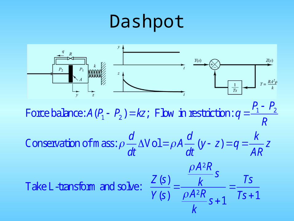
Dashpot
1 21 2
2
2
Force balance: ( ) ; Flow in restriction:
Conservation of mass: Vol ( )
( )Take L-transform and solve:
( ) 11
P PA P P kz q
Rd d k
A y z q zdt dt AR
A RsZ s Tsk
A RY s Tssk

Proportional + Integral controller
Lastpage
Rest as before
( )( 1)
( ) ( 1)
At low frequency, ( )( 1)
1 (1 )
b K a b TsTF
a b aKTs a b s Ts
aKT a b Ts
bTF
a Ts

Proportional +derivative control
Spring force: k(y-z) instead of kz; new TF=1-oldTF
( )( 1)
( ) ( 1)
At low frequency, ( ) ( 1)
( 1)
b K a b TsTF
a b aK a b s Ts
aK a b s Ts
bTF Ts
a

PID controller
w
Force Balance: k1z=AP1; k2(y-w)=AP1+AP2
1( )kd
A w z zdt AR
2 2 1( )P k kd
A w y w zdt R AR R
2
12 2 2 2
2
1 2 2 1
( )Solve for:
2( ) ( ) 1
A Rs
kZ sA R A R A R A RY s s sk k k k

21 2 1 2
21 1 2 1 2
21 1 2 1 2
1 22
1 1
( )( ( 2 ) 1)
( ) ( ( 2 ) 1)
At low frequency, ( )( ( 2 ) 1)
2 1 ( )
K a b TT s T T sbTF
a b aKT s a b s TT s T T s
aKT a b TT s T T s
T TbTF T s
a T T s
Block diagram representation

e
zw
3 3
3 3 3 3
4 4
4 2 4 2
1 2 21 2
1 1
1 2
1
2
1
2
2
l lz x y x y
l l l l
l lw z x y
l l l l
l l le w y k x k y
l l
K K Ky e k x k y
s s sKk
y xs Kk

Thermal systems
Conservation of heat energy:
iin out i
dC h h h
dt R R
1( ) ( ) ( )
1 1i i
Rs h s s
RCs RCs

a av k v
a a bv Ri v
b mv K
i vq K
i o
dhC q q
dt 1
oo
q hR