Embed Size (px)
Citation preview
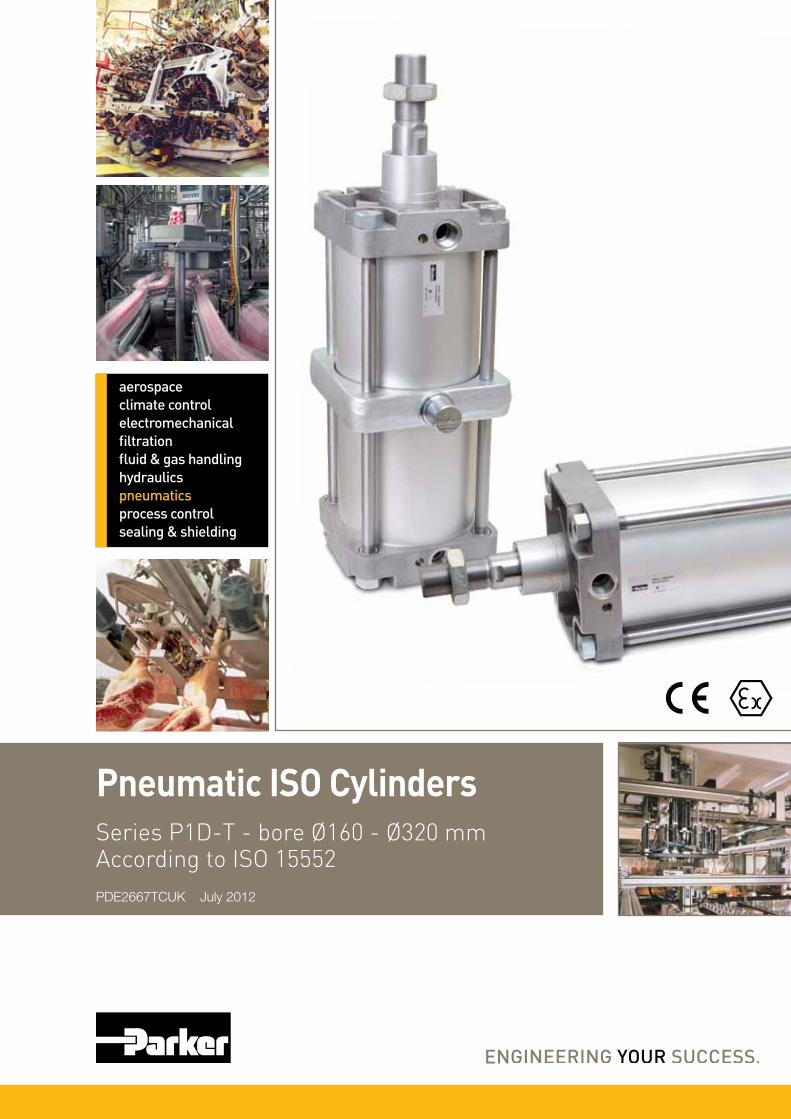
Pneumatic ISO Cylinders
aerospaceclimate control electromechanicalfiltrationfluid & gas handlinghydraulicspneumaticsprocess controlsealing & shielding
Series P1D-T - bore Ø160 - Ø320 mmAccording to ISO 15552PDE2667TCUK July 2012
2
Parker Hannifin CorporationPneumatic Division - Europe
PDE2667TCUK
P1D-T Pneumatic ISO Cylinders - Ø160 - Ø320 mm
SALE CONDITIONSThe items described in this document are available for sale by Parker Hannifin Corporation, its subsidiaries or its authorized distributors. Any sale contract entered into by Parker will be governed by the provisions stated in Parker’s standard terms and conditions of sale (copy available upon request).
WARNING
FAILURE OR IMPROPER SELECTION OR IMPROPER USE OF THE PRODUCTS AND/OR SYSTEMS DESCRIBED HEREIN OR RELATED ITEMS CAN CAUSE DEATH, PERSONAL INJURY ANDPROPERTY DAMAGE.This document and other information from Parker Hannifin Corporation, its subsidiaries and authorized distributors provide product and/or system options for further investigation by users having technical expertise. It is important that you analyze all aspects of your application and review the information concerning the product or system in the current product catalog. Due to the variety of operating conditions and applications for these products or systems, the user, through its own analysis and testing, is solely responsible for making the final selection of the products and systems and assuring that all performance, safety and warning requirements of the application are met. The products described herein, including without limitation, product features, specifications, designs, availability and pricing, are subject to change by Parker Hannifin Corporation and its subsidiaries at any time without notice.
NoteAll technical data in this catalogue are typical data only.Air quality is essential for maximum cylinder service life (see ISO 8573).
ImportantBefore attempting any external or internal work on the cylinder or any connected components, make sure the cylinder is vented and dis connect the air supply in order to ensure isolation of the air supply.
Contents page
P1D-T – ISO 15552 Cylinder Range ................................................................3
Cylinder forces, double acting variants ............................................................4
Main data : P1D-T ..........................................................................................4
Operating and environmental data ..................................................................4
General technical data ....................................................................................5
Material specification - Bores Ø160, Ø200 and Ø250 mm ..............................5
Material specification - Bores Ø320 mm .........................................................6
Order key code P1D-T ....................................................................................7
Standard strokes ............................................................................................7
Order code standard strokes P1D-T ...............................................................8
Dimensions .....................................................................................................9
Cylinder mountings ................................................................................10 - 12
Piston rod mountings ....................................................................................13
Sensors .................................................................................................14 - 16
Seal kits ........................................................................................................17
Introduction to ATEX directive ................................................................18 - 21
3
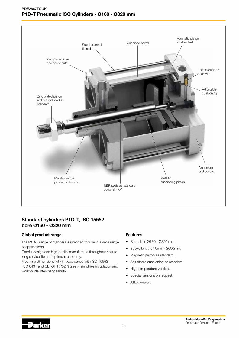
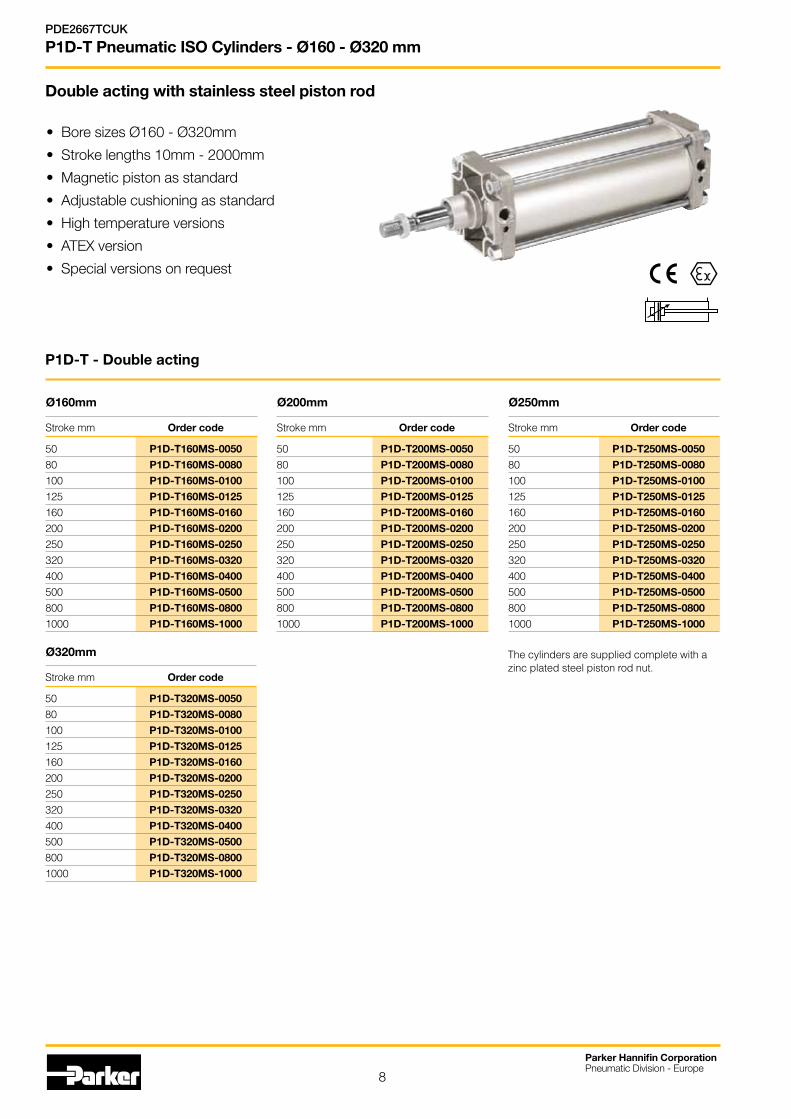
Standard cylinders P1D-T, ISO 15552bore Ø160 - Ø320 mm
Global product range
The P1D-T range of cylinders is intended for use in a wide range of applications.Careful design and high quality manufacture throughout ensure long service life and optimum economy.Mounting dimensions fully in accordance with ISO 15552(ISO 6431 and CETOP RP52P) greatly simplifies installation and world-wide interchangeability.
Features
• Bore sizes Ø160 - Ø320 mm.
• Stroke lengths 10mm - 2000mm.
• Magnetic piston as standard.
• Adjustable cushioning as standard.
• High temperature version.
• Special versions on request.
• ATEX version.
Parker Hannifin CorporationPneumatic Division - Europe
PDE2667TCUK
P1D-T Pneumatic ISO Cylinders - Ø160 - Ø320 mm
Zinc plated steelend cover nuts
Zinc plated pistonrod nut included asstandard
Metal-polymerpiston rod bearing
NBR seals as standardoptional FKM
Metalliccushioning piston
Aluminiumend covers
Adjustablecushioning
Brass cushionscrews
Magnetic pistonas standardAnodised barrelStainless steel
tie rods
4
Parker Hannifin CorporationPneumatic Division - Europe
PDE2667TCUK
P1D-T Pneumatic ISO Cylinders - Ø160 - Ø320 mm
Operating and environmental data
Operating medium For best possible service life and trouble-free operation dry, filtered compressed air to ISO 8573-1:2010 quality
class 3.4.3 should be used. This specifies a dew point of +3oC for indoor operation (a lower dew point should be
selected for outdoor operation) and is in line with the air quality from most standard compressors with a standard
filter.
Operating pressure 1,0 bar to 10 bar
Ambient temperature
Standard version -20oC to +80oC
High temperature version -10oC to +140oC
Pre-lubricated Further lubrication is normally not necessary. If additional lubrication is introduced it must be continued.
Corrosion resistance High resistance to corrosion and chemicals. Materials and surface treatment have been selected for industrial
applications where solvents and detergents are frequently used.
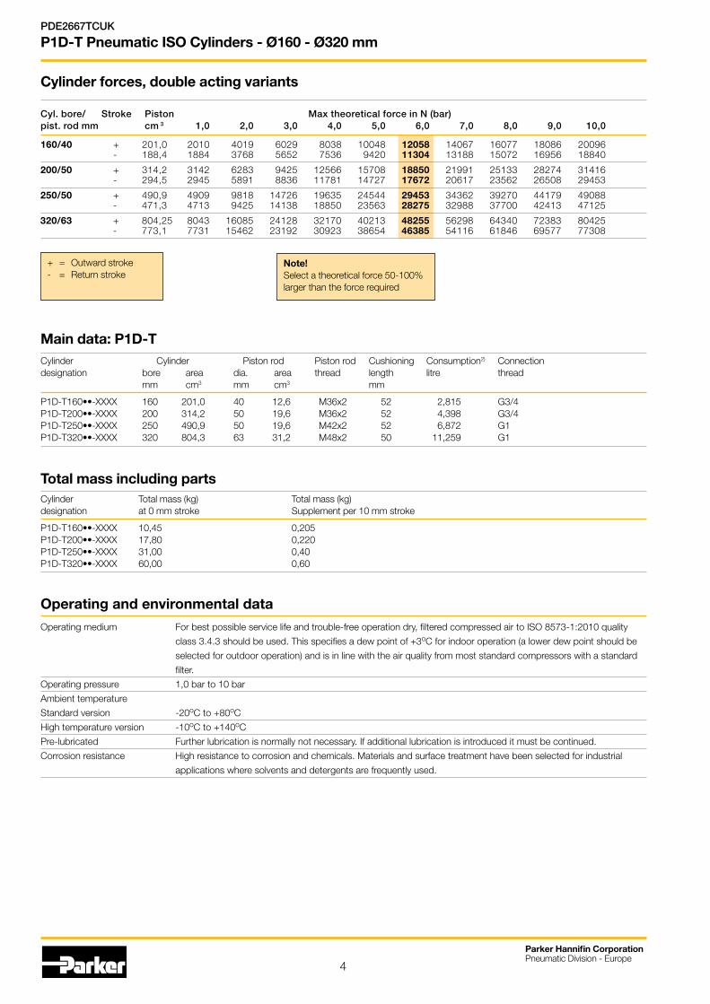
Total mass including partsCylinder Total mass (kg) Total mass (kg) designation at 0 mm stroke Supplement per 10 mm stroke
P1D-T160••-XXXX 10,45 0,205P1D-T200••-XXXX 17,80 0,220P1D-T250••-XXXX 31,00 0,40P1D-T320••-XXXX 60,00 0,60
Cyl. bore/ Stroke Piston Max theoretical force in N (bar) pist. rod mm cm 3 1,0 2,0 3,0 4,0 5,0 6,0 7,0 8,0 9,0 10,0
160/40 + 201,0 2010 4019 6029 8038 10048 12058 14067 16077 18086 20096 - 188,4 1884 3768 5652 7536 9420 11304 13188 15072 16956 18840
200/50 + 314,2 3142 6283 9425 12566 15708 18850 21991 25133 28274 31416 - 294,5 2945 5891 8836 11781 14727 17672 20617 23562 26508 29453
250/50 + 490,9 4909 9818 14726 19635 24544 29453 34362 39270 44179 49088 - 471,3 4713 9425 14138 18850 23563 28275 32988 37700 42413 47125
320/63 + 804,25 8043 16085 24128 32170 40213 48255 56298 64340 72383 80425 - 773,1 7731 15462 23192 30923 38654 46385 54116 61846 69577 77308
Cylinder forces, double acting variants
Main data: P1D-T Cylinder Cylinder Piston rod Piston rod Cushioning Consumption2) Connection designation bore area dia. area thread length litre thread mm cm3 mm cm3 mm
P1D-T160••-XXXX 160 201,0 40 12,6 M36x2 52 2,815 G3/4P1D-T200••-XXXX 200 314,2 50 19,6 M36x2 52 4,398 G3/4P1D-T250••-XXXX 250 490,9 50 19,6 M42x2 52 6,872 G1P1D-T320••-XXXX 320 804,3 63 31,2 M48x2 50 11,259 G1
Note!Select a theoretical force 50-100% larger than the force required
+ = Outward stroke- = Return stroke
5
Parker Hannifin CorporationPneumatic Division - Europe
PDE2667TCUK
P1D-T Pneumatic ISO Cylinders - Ø160 - Ø320 mm
General technical data
Product type Standard cylinder according to ISO 15552
Bore size 160 - 320 mm
Stroke length 10-2000 mm
Versions P1D-T...XX Double acting
Cushioning Adjustable air cushioning
Position sensing Proximity sensor
Installation P1D cylinder and piston rod mountings
Mounting position Any
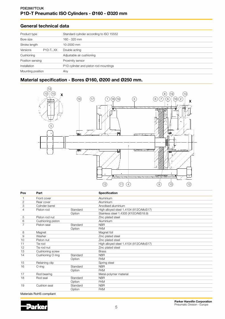
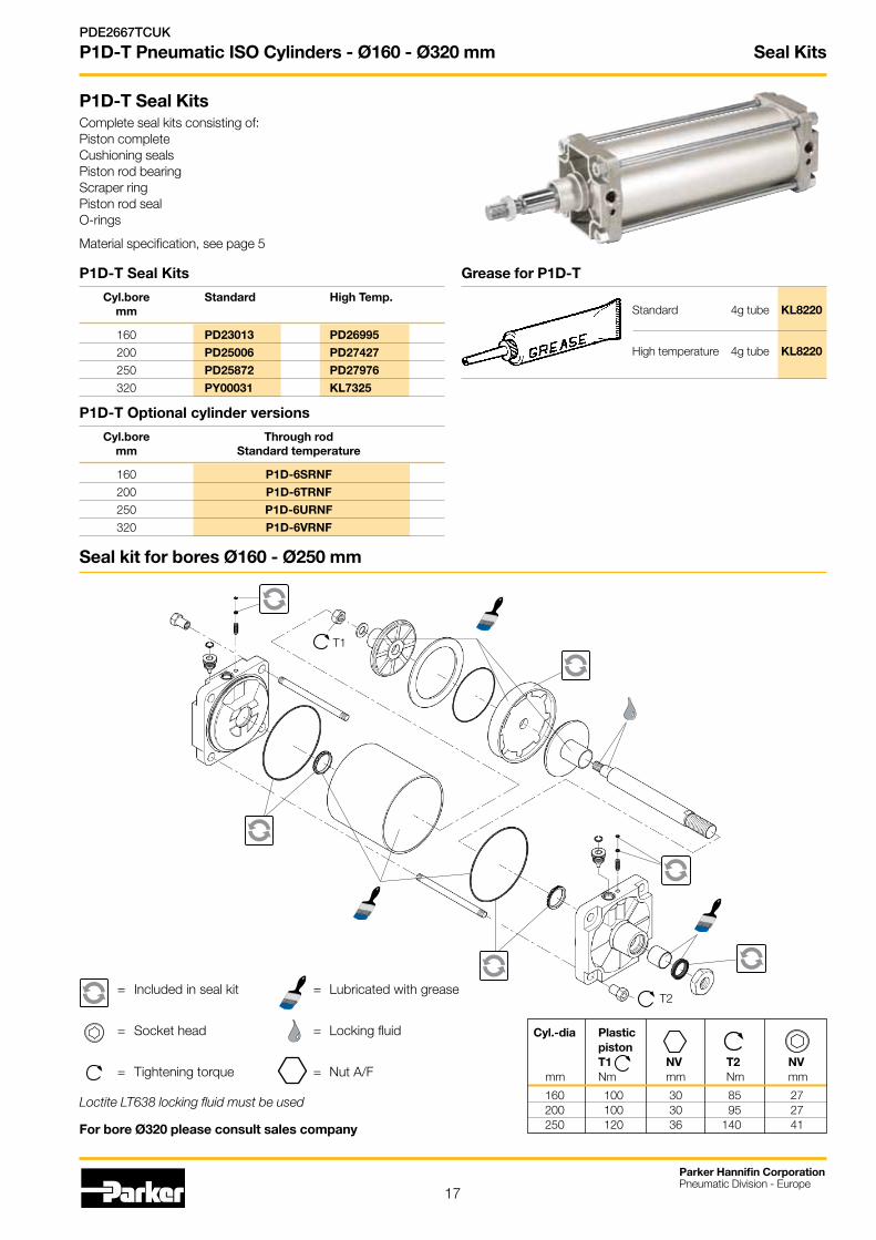
Material specification - Bores Ø160, Ø200 and Ø250 mm.
Pos Part Specification
1 Front cover Aluminium 2 Rear cover Aluminium 3 Cylinder barrel Anodised aluminium 4 Piston rod Standard High alloyed steel 1.4104 (X12CrMoS17) Option Stainless steel 1.4305 (X10CrNiS18.9) 5 Piston rod nut Zinc plated steel 6 Cushioning piston Aluminium 7 Piston seal Standard NBR Option FKM 8 Magnet Magnet foil 9 Washer Zinc plated steel 10 Piston nut Zinc plated steel 11 Tie rod High alloyed steel 1.4104 (X12CrMoS17) 12 Tie rod nut Zinc plated steel 13 Cushioning screw Brass 14 Cushioning O ring Standard NBR Option FKM 15 Retaining clip Spring steel 16 O ring Standard NBR Option FKM 17 Rod bearing Metal-polymer material 18 Rod seal Standard NBR Option FKM 19 Cushion seal Standard NBR Option FKM
4
618
11 10
1 316
9 12
5
12
17 19 7 6 16 2
8 1319
X
1513
14
X
Materials RoHS compliant
6
Parker Hannifin CorporationPneumatic Division - Europe
PDE2667TCUK
P1D-T Pneumatic ISO Cylinders - Ø160 - Ø320 mm
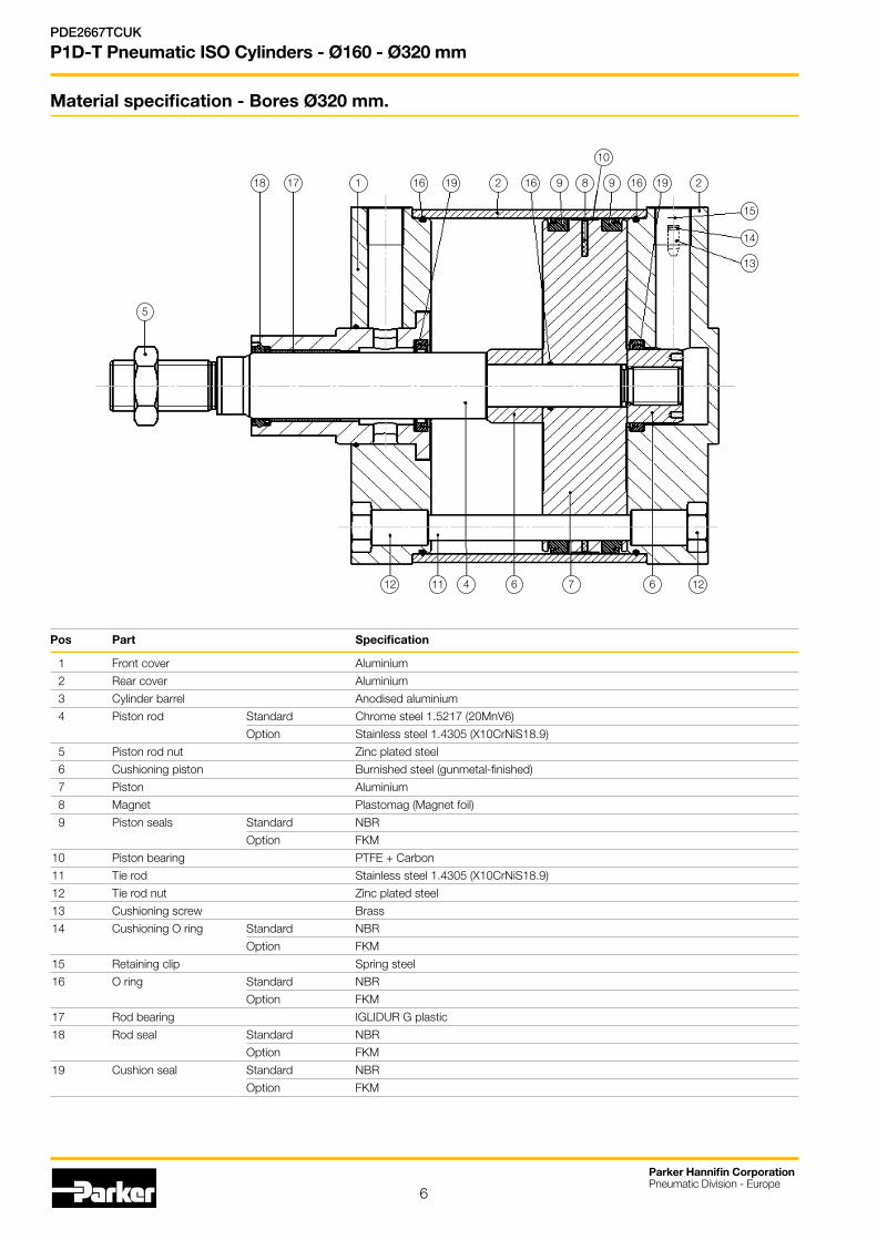
Material specification - Bores Ø320 mm.
Pos Part Specification
1 Front cover Aluminium
2 Rear cover Aluminium
3 Cylinder barrel Anodised aluminium
4 Piston rod Standard Chrome steel 1.5217 (20MnV6)
Option Stainless steel 1.4305 (X10CrNiS18.9)
5 Piston rod nut Zinc plated steel
6 Cushioning piston Burnished steel (gunmetal-finished)
7 Piston Aluminium
8 Magnet Plastomag (Magnet foil)
9 Piston seals Standard NBR
Option FKM
10 Piston bearing PTFE + Carbon
11 Tie rod Stainless steel 1.4305 (X10CrNiS18.9)
12 Tie rod nut Zinc plated steel
13 Cushioning screw Brass
14 Cushioning O ring Standard NBR
Option FKM
15 Retaining clip Spring steel
16 O ring Standard NBR
Option FKM
17 Rod bearing IGLIDUR G plastic
18 Rod seal Standard NBR
Option FKM
19 Cushion seal Standard NBR
Option FKM
Pneumatic Zylinder Ø320
Pos Part Specification1 Front cover Aluminium2 Rear cover Aluminium3 Cylinder barrel Anodised aluminium4 Piston Rod Standard Chrome steel 1.5217 (20MnV6)
Option Stainless steel 1.4305 (X10CrNiS18.9)5 Piston rod nut Zinc plated steel6 Cushioning Piston Burnished steel (gunmetal-finished)7 Piston Aluminium8 Magnet Plastomag (Magnet foil)9 Piston seals Standard NBR
Option FKM10 Piston bearing PTFE + Carbon11 Tie rod Stainless steel 1.4305 (X10CrNiS18.9)12 Tie rod nut Zinc plated steel13 Cushioning screw Brass14 Cushioning O ring Standard NBR
Option FKM15 Retaining clip Spring steel16 O ring Standard NBR
Option FKM17 Rod bearing IGLIDUR G plastic18 Rod seal Standard NBR
Option FKM19 Cushion seal Standard NBR
Option FKM
NOTE : ONLY VALID FOR BORE Ø3204 6
18
11
1 16 9
12 12
17 19
7 6
162 8
13
199 2
15
16
14
5
10
7
Parker Hannifin CorporationPneumatic Division - Europe
PDE2667TCUK
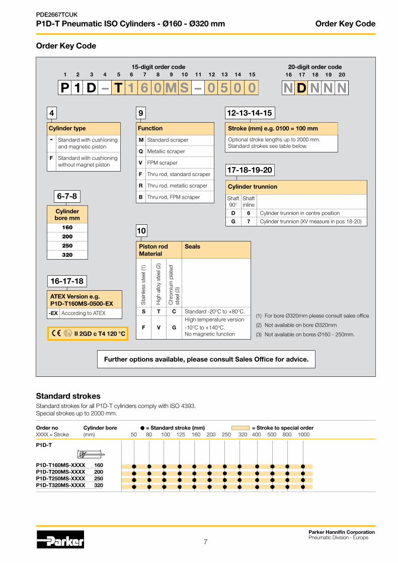
P1D-T Pneumatic ISO Cylinders - Ø160 - Ø320 mm Order Key Code
1 2 3 4 5 6 7 8 9 10 11 12 13 14 15
P 1 D – T 1 6 0 M S – 0 5 0 0
Order Key Code
15-digit order code
6-7-8
Stroke (mm) e.g. 0100 = 100 mm
Optional stroke lengths up to 2000 mm.Standard strokes see table below.
12-13-14-15
Cylinder type
- Standard with cushioning and magnetic piston
F Standard with cushioning without magnet piston
4
Function
M Standard scraper
Q Metallic scraper
V FPM scraper
F Thru rod, standard scraper
R Thru rod, metallic scraper
B Thru rod, FPM scraper
9
10
ATEX Version e.g. P1D-T160MS-0500-EX
-EX According to ATEX
II 2GD c T4 120 °C
Cylinder bore mm
160
200
250
320
Further options available, please consult Sales Office for advice.
Standard strokes Standard strokes for all P1D-T cylinders comply with ISO 4393.Special strokes up to 2000 mm.
Order no Cylinder bore = Standard stroke (mm) = Stroke to special order XXXX = Stroke (mm) 50 80 100 125 160 200 250 320 400 500 800 1000
P1D-T
P1D-T160MS-XXXX 160P1D-T200MS-XXXX 200P1D-T250MS-XXXX 250P1D-T320MS-XXXX 320
Cylinder trunnion
Shaft Shaft 90O inline
D 6 Cylinder trunnion in centre position
G 7 Cylinder trunnion (XV measure in pos 18-20)
16 17 18 19 20
N D N N N
20-digit order code
17-18-19-20
16-17-18
Piston rod Seals Material
S T C Standard -20OC to +80OC. High temperature version F V G -10OC to +140OC. No magnetic function
Sta
inle
ss s
teel
(1)
Hig
h al
loy
stee
l (2)
Chr
omiu
m p
late
dst
eel (
3)
(1) For bore Ø320mm please consult sales office
(2) Not available on bore Ø320mm
(3) Not available on bores Ø160 - 250mm.
8
Parker Hannifin CorporationPneumatic Division - Europe
PDE2667TCUK
P1D-T Pneumatic ISO Cylinders - Ø160 - Ø320 mm
• BoresizesØ160-Ø320mm
• Strokelengths10mm-2000mm
• Magneticpistonasstandard
• Adjustablecushioningasstandard
• Hightemperatureversions
• ATEXversion
• Specialversionsonrequest
P1D-T - Double acting
Stroke mm Order code
50 P1D-T160MS-0050
80 P1D-T160MS-0080
100 P1D-T160MS-0100
125 P1D-T160MS-0125
160 P1D-T160MS-0160
200 P1D-T160MS-0200
250 P1D-T160MS-0250
320 P1D-T160MS-0320
400 P1D-T160MS-0400
500 P1D-T160MS-0500
800 P1D-T160MS-0800
1000 P1D-T160MS-1000
Ø160mm
The cylinders are supplied complete with a zinc plated steel piston rod nut.
Stroke mm Order code
50 P1D-T200MS-0050
80 P1D-T200MS-0080
100 P1D-T200MS-0100
125 P1D-T200MS-0125
160 P1D-T200MS-0160
200 P1D-T200MS-0200
250 P1D-T200MS-0250
320 P1D-T200MS-0320
400 P1D-T200MS-0400
500 P1D-T200MS-0500
800 P1D-T200MS-0800
1000 P1D-T200MS-1000
Ø200mm
Stroke mm Order code
50 P1D-T250MS-0050
80 P1D-T250MS-0080
100 P1D-T250MS-0100
125 P1D-T250MS-0125
160 P1D-T250MS-0160
200 P1D-T250MS-0200
250 P1D-T250MS-0250
320 P1D-T250MS-0320
400 P1D-T250MS-0400
500 P1D-T250MS-0500
800 P1D-T250MS-0800
1000 P1D-T250MS-1000
Ø250mm
Stroke mm Order code
50 P1D-T320MS-0050
80 P1D-T320MS-0080
100 P1D-T320MS-0100
125 P1D-T320MS-0125
160 P1D-T320MS-0160
200 P1D-T320MS-0200
250 P1D-T320MS-0250
320 P1D-T320MS-0320
400 P1D-T320MS-0400
500 P1D-T320MS-0500
800 P1D-T320MS-0800
1000 P1D-T320MS-1000
Ø320mm
Double acting with stainless steel piston rod
9
Parker Hannifin CorporationPneumatic Division - Europe
PDE2667TCUK
P1D-T Pneumatic ISO Cylinders - Ø160 - Ø320 mm
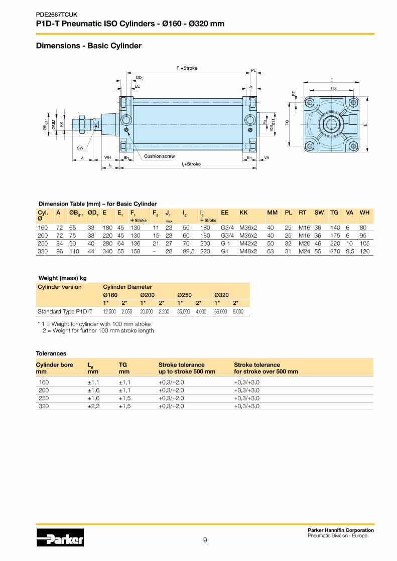
Dimension Table (mm) – for Basic CylinderCyl. Ø
A ØBd11 ØD7 E E1 F1
+ Stroke
F3 J1
max.
l2 l8+ Stroke
EE KK MM PL RT SW TG VA WH
160 72 65 33 180 45 130 11 23 50 180 G3/4 M36x2 40 25 M16 36 140 6 80200 72 75 33 220 45 130 15 23 60 180 G3/4 M36x2 40 25 M16 36 175 6 95250 84 90 40 280 64 136 21 27 70 200 G 1 M42x2 50 32 M20 46 220 10 105320 96 110 44 340 55 158 – 28 89,5 220 G1 M48x2 63 31 M24 55 270 9,5 120
Cushion screw
l8+Stroke
F1+Stroke
Weight (mass) kg
Cylinder version Cylinder DiameterØ160 Ø200 Ø250 Ø3201* 2* 1* 2* 1* 2* 1* 2*
Standard Type P1D-T 12.500 2.050 20.000 2.200 35.000 4.000 66.000 6.000
* 1 = Weight for cylinder with 100 mm stroke 2 = Weight for further 100 mm stroke length
Tolerances
Cylinder bore L8 TG Stroke tolerance Stroke tolerance mm mm mm up to stroke 500 mm for stroke over 500 mm
160 ±1,1 ±1,1 +0,3/+2,0 +0,3/+3,0 200 ±1,6 ±1,1 +0,3/+2,0 +0,3/+3,0 250 ±1,6 ±1,5 +0,3/+2,0 +0,3/+3,0 320 ±2,2 ±1,5 +0,3/+2,0 +0,3/+3,0
Dimensions - Basic Cylinder
Mountings
10
Parker Hannifin CorporationPneumatic Division - Europe
PDE2667TCUK
P1D-T Pneumatic ISO Cylinders - Ø160 - Ø320 mm
Cylinder mountings
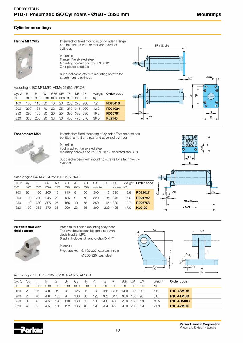
AccordingtoISOMF1/MF2,VDMA24562,AFNOR
Cyl. Ø E R W ØFB MF TF UF ZF Weight Order codemm mm mm mm mm mm mm mm mm kg
160 180 115 60 18 20 230 275 280 7.2 PD23410
200 220 135 70 22 25 270 315 300 12.2 PD24924
250 280 165 80 26 25 330 380 330 19.2 PD25761
320 353 200 90 33 30 400 475 370 38.0 KL9140
SA+Stroke
XA+Stroke
Foot bracket MS1 Intended for fixed mounting of cylinder. Foot bracket can be fitted to front and rear end covers of cylinder. Materials Foot bracket: Passivated steel Mounting screws acc. to DIN 912: Zinc-plated steel 8.8 Supplied in pairs with mounting screws for attachment to cylinder .
Pivot bracket with Intended for flexible mounting of cylinder. rigid bearing The pivot bracket can be combined with clevis bracket MP2. Bracket includes pin and circlips DIN 471
Materials
Pivot bracket: Ø 160-200: cast aluminium
Ø 250-320: cast steel
According to ISO MS1, VDMA 24 562, AFNOR
Cyl. Ø A2 E G1 AB AH AT AU SA TR XA Weight Order codemm mm mm mm mm mm mm mm + stroke + stroke kg
160 80 180 205 18 115 8 60 300 115 320 3.8 PD22027
200 100 220 245 22 135 9 70 320 135 345 5.0 PD24792
250 110 280 305 26 165 10 75 350 165 380 9.7 PD25758
320 130 353 370 35 200 23 85 390 200 425 17.0 KL9139
According to CETOP RP 107 P, VDMA 24 562, AFNOR
Cyl. Ø Ød2 l3 l5 G1 G2 G3 H6 K1 K2 R1 ØS5 CA EM Weight Order codemm mm mm mm mm mm mm mm mm mm mm mm mm mm kg
160 20 36 4.0 97 88 126 25 118 156 31.5 14.0 115 90 6.5 P1C-4SMDB
200 26 40 4.0 105 90 130 30 122 162 31.5 18.0 135 90 8.0 P1C-4TMDB
250 33 45 4.5 128 110 160 35 150 200 40 22.0 165 110 13.5 P1C-4UMDC
320 40 55 4.5 150 122 186 40 170 234 45 26.0 200 120 21.9 P1C-4VMDC
ZF + Stroke
Flange MF1/MF2 Intended for fixed mounting of cylinder. Flange can be fitted to front or rear end cover of cylinder. Materials Flange: Passivated steel Mounting screws acc. to DIN 6912: Zinc-plated steel 8.8 Supplied complete with mounting screws for attachment to cylinder.
Mountings
11
Parker Hannifin CorporationPneumatic Division - Europe
PDE2667TCUK
P1D-T Pneumatic ISO Cylinders - Ø160 - Ø320 mm
XD+Stroke
XN+Stroke
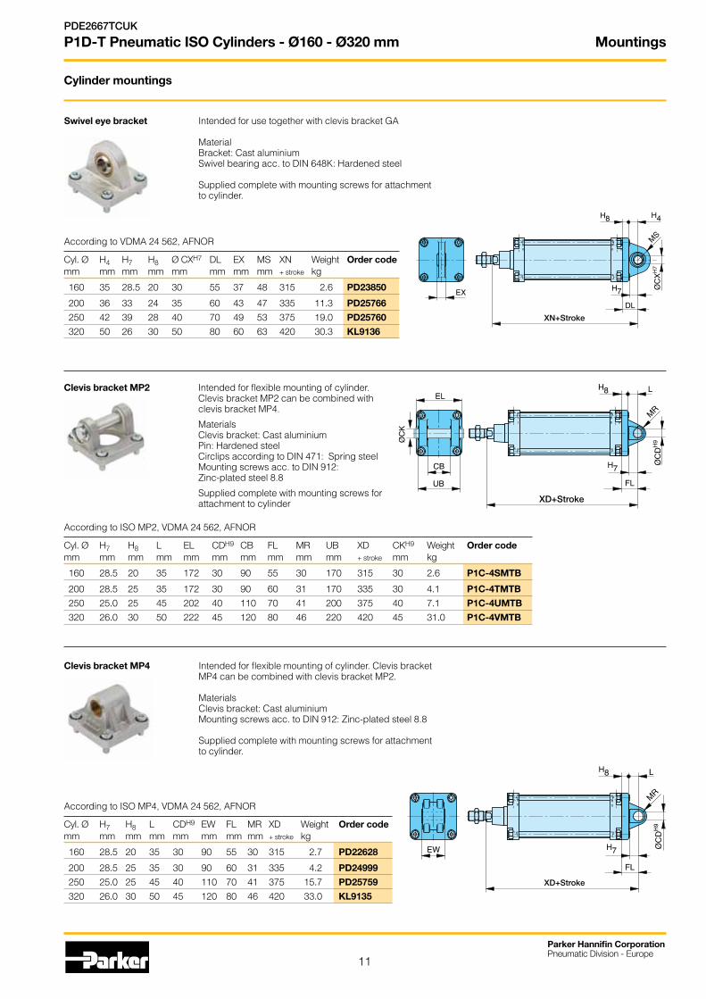
Clevis bracket MP2 Intended for flexible mounting of cylinder. Clevis bracket MP2 can be combined with clevis bracket MP4. MaterialsClevis bracket: Cast aluminium Pin: Hardened steel Circlips according to DIN 471: Spring steel Mounting screws acc. to DIN 912: Zinc-plated steel 8.8 Supplied complete with mounting screws for attachment to cylinder
According to VDMA 24 562, AFNOR
Cyl. Ø H4 H7 H8 Ø CXH7 DL EX MS XN Weight Order codemm mm mm mm mm mm mm mm + stroke kg
160 35 28.5 20 30 55 37 48 315 2.6 PD23850
200 36 33 24 35 60 43 47 335 11.3 PD25766
250 42 39 28 40 70 49 53 375 19.0 PD25760
320 50 26 30 50 80 60 63 420 30.3 KL9136
Swivel eye bracket Intended for use together with clevis bracket GA Material Bracket: Cast aluminium Swivel bearing acc. to DIN 648K: Hardened steel Supplied complete with mounting screws for attachment to cylinder.
Cylinder mountings
According to ISO MP2, VDMA 24 562, AFNOR
Cyl. Ø H7 H8 L EL CDH9 CB FL MR UB XD CKH9 Weight Order codemm mm mm mm mm mm mm mm mm mm + stroke mm kg
160 28.5 20 35 172 30 90 55 30 170 315 30 2.6 P1C-4SMTB
200 28.5 25 35 172 30 90 60 31 170 335 30 4.1 P1C-4TMTB
250 25.0 25 45 202 40 110 70 41 200 375 40 7.1 P1C-4UMTB
320 26.0 30 50 222 45 120 80 46 220 420 45 31.0 P1C-4VMTB
Clevis bracket MP4 Intended for flexible mounting of cylinder. Clevis bracket MP4 can be combined with clevis bracket MP2. Materials Clevis bracket: Cast aluminium Mounting screws acc. to DIN 912: Zinc-plated steel 8.8 Supplied complete with mounting screws for attachment to cylinder .
XD+Stroke
According to ISO MP4, VDMA 24 562, AFNOR
Cyl. Ø H7 H8 L CDH9 EW FL MR XD Weight Order codemm mm mm mm mm mm mm mm + stroke kg
160 28.5 20 35 30 90 55 30 315 2.7 PD22628
200 28.5 25 35 30 90 60 31 335 4.2 PD24999
250 25.0 25 45 40 110 70 41 375 15.7 PD25759
320 26.0 30 50 45 120 80 46 420 33.0 KL9135
Mountings
12
Parker Hannifin CorporationPneumatic Division - Europe
PDE2667TCUK
P1D-T Pneumatic ISO Cylinders - Ø160 - Ø320 mm
Cylinder mountings
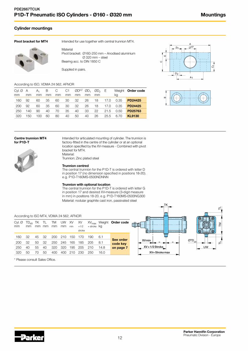
Pivot bracket for MT4 Intended for use together with central trunnion MT4. Material Pivot bracket: Ø160-250 mm – Anodised aluminium Ø 320 mm – steel Bearing acc. to DIN 1850 C Supplied in pairs.
According to ISO, VDMA 24 562, AFNOR
Cyl. Ø A A1 B C C1 ØDH7 ØD1 ØD2 E Weight Order codemm mm mm mm mm mm mm mm mm kg
160 92 60 35 60 30 32 26 18 17.0 0.35 PD24425
200 92 60 35 60 30 32 26 18 17.0 0.35 PD24425
250 140 90 40 70 35 40 33 22 21.5 0.50 PD25763
320 150 100 60 80 40 50 40 26 25.5 6.70 KL9130
Centre trunnion MT4 Intended for articulated mounting of cylinder. The trunnion is for P1D-T factory-fitted in the centre of the cylinder or at an optional location specified by the XV-measure - Combined with pivot bracket for MT4. Material: Trunnion: Zinc plated steel Trunnion centred The central trunnion for the P1D-T is ordered with letter D in position 17 (no dimension specified in positions 18-20). e.g. P1D-T160MS-0500NDNNN
Trunnion with optional location The central trunnion for the P1D-T is ordered with letter G in position 17 and desired XV-measure (3-digit measure in mm) in positions 18-20. e.g. P1D-T160MS-0500NG300 Material: nodular graphite cast iron, passivated steel
XV min
XV + 1/2 Stroke
XV+ Stroke max
According to ISO MT4, VDMA 24 562, AFNOR
Cyl. Ø TDe9 TK TL TM UW XV XV XVmax Weight Order codemm mm mm mm mm mm min +1/2 +stroke kg stroke
160 32 45 32 200 210 150 170 190 6.1
200 32 50 32 250 245 165 185 205 8.1
250 40 55 40 320 320 195 205 210 14.8
320 50 70 50 400 400 210 230 250 16.0
* Please consult Sales Office.
See order code key on page 7
Mountings
13
Parker Hannifin CorporationPneumatic Division - Europe
PDE2667TCUK
P1D-T Pneumatic ISO Cylinders - Ø160 - Ø320 mm
Piston rod mountings
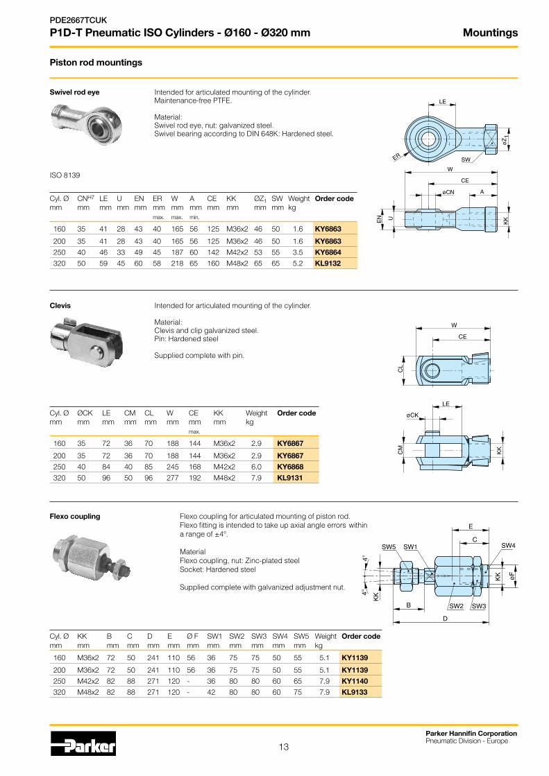
Swivel rod eye Intended for articulated mounting of the cylinder.Maintenance-free PTFE. Material: Swivel rod eye, nut: galvanized steel. Swivel bearing according to DIN 648K: Hardened steel.
ISO 8139
Cyl. Ø CNH7 LE U EN ER W A CE KK ØZ1 SW Weight Order codemm mm mm mm mm mm mm mm mm mm mm mm kg max. max. min.
160 35 41 28 43 40 165 56 125 M36x2 46 50 1.6 KY6863
200 35 41 28 43 40 165 56 125 M36x2 46 50 1.6 KY6863
250 40 46 33 49 45 187 60 142 M42x2 53 55 3.5 KY6864
320 50 59 45 60 58 218 65 160 M48x2 65 65 5.2 KL9132
Clevis Intended for articulated mounting of the cylinder. Material: Clevis and clip galvanized steel. Pin: Hardened steel Supplied complete with pin.
Cyl. Ø ØCK LE CM CL W CE KK Weight Order codemm mm mm mm mm mm mm mm kg max.
160 35 72 36 70 188 144 M36x2 2.9 KY6867
200 35 72 36 70 188 144 M36x2 2.9 KY6867
250 40 84 40 85 245 168 M42x2 6.0 KY6868
320 50 96 50 96 277 192 M48x2 7.9 KL9131
Flexo coupling Flexo coupling for articulated mounting of piston rod. Flexo fitting is intended to take up axial angle errors within a range of ±4°. Material Flexo coupling, nut: Zinc-plated steel Socket: Hardened steel Supplied complete with galvanized adjustment nut.
Cyl. Ø KK B C D E Ø F SW1 SW2 SW3 SW4 SW5 Weight Order codemm mm mm mm mm mm mm mm mm mm mm mm kg
160 M36x2 72 50 241 110 56 36 75 75 50 55 5.1 KY1139
200 M36x2 72 50 241 110 56 36 75 75 50 55 5.1 KY1139
250 M42x2 82 88 271 120 - 36 80 80 60 65 7.9 KY1140
320 M48x2 82 88 271 120 - 42 80 80 60 75 7.9 KL9133
Sensors
14
Parker Hannifin CorporationPneumatic Division - Europe
PDE2667TCUK
P1D-T Pneumatic ISO Cylinders - Ø160 - Ø320 mm
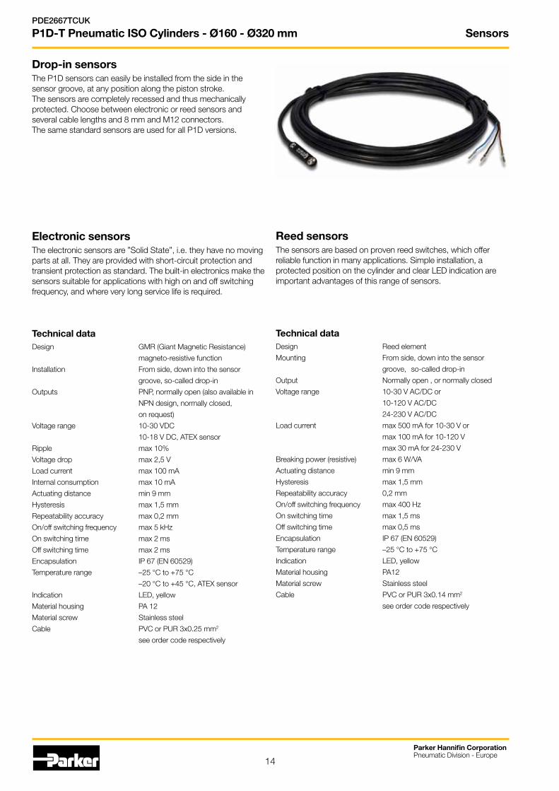
Drop-in sensors The P1D sensors can easily be installed from the side in the sensor groove, at any position along the piston stroke.The sensors are completely recessed and thus mechanically protected. Choose between electronic or reed sensors and several cable lengths and 8 mm and M12 con nectors.The same standard sensors are used for all P1D versions.
Electronic sensors The electronic sensors are ”Solid State”, i.e. they have no moving parts at all. They are provided with short-circuit protection and transient protection as standard. The built-in electronics make the sensors suitable for applications with high on and off switching frequency, and where very long service life is required.
Technical dataDesign GMR (Giant Magnetic Resistance)
magneto-resistive function
Installation From side, down into the sensor
groove, so-called drop-in
Outputs PNP, normally open (also available in
NPN design, normally closed,
on request)
Voltage range 10-30 VDC
10-18 V DC, ATEX sensor
Ripple max 10%
Voltage drop max 2,5 V
Load current max 100 mA
Internal consumption max 10 mA
Actuating distance min 9 mm
Hysteresis max 1,5 mm
Repeatability accuracy max 0,2 mm
On/offswitchingfrequency max5kHz
On switching time max 2 ms
Off switching time max 2 ms
Encapsulation IP 67 (EN 60529)
Temperature range –25 °C to +75 °C
–20 °C to +45 °C, ATEX sensor
Indication LED, yellow
Material housing PA 12
Material screw Stainless steel
Cable PVC or PUR 3x0.25 mm2
see order code respectively
Reed sensors The sensors are based on proven reed switches, which offer reliable function in many applications. Simple installation, a protected position on the cylinder and clear LED indication are important advantages of this range of sensors.
Technical dataDesign Reed element
Mounting From side, down into the sensor
groove, so-called drop-in
Output Normally open , or normally closed
Voltagerange 10-30VAC/DCor
10-120VAC/DC
24-230VAC/DC
Load current max 500 mA for 10-30 V or
max 100 mA for 10-120 V
max 30 mA for 24-230 V
Breakingpower(resistive) max6W/VA
Actuating distance min 9 mm
Hysteresis max 1,5 mm
Repeatability accuracy 0,2 mm
On/offswitchingfrequency max400Hz
On switching time max 1,5 ms
Off switching time max 0,5 ms
Encapsulation IP 67 (EN 60529)
Temperature range –25 °C to +75 °C
Indication LED, yellow
Material housing PA12
Material screw Stainless steel
Cable PVC or PUR 3x0.14 mm2
see order code respectively
Sensors
15
Parker Hannifin CorporationPneumatic Division - Europe
PDE2667TCUK
P1D-T Pneumatic ISO Cylinders - Ø160 - Ø320 mm
Sensors
Brown
Black
Blue
+(–) V AC/DC
Signal
–(+) V AC/DC
Brown
Black
Blue
Brown
Blue
P8S-GRFLX / P8S-GRFLX2
+(–) V AC/DC
Signal–(+) V AC/DC
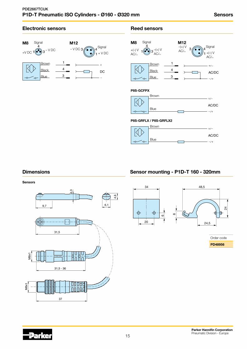
M8 M12
+V DC
Signal
– V DC+ V DC
Signal– V DC
M8 M12
Electronic sensors Reed sensors
P8S-GCFPX
Brown
Blue
Dimensions Sensor mounting - P1D-T 160 - 320mm
Order code
PD48956
34
20
6
48,5
24,5
8
24
Sensors
16
Parker Hannifin CorporationPneumatic Division - Europe
PDE2667TCUK
P1D-T Pneumatic ISO Cylinders - Ø160 - Ø320 mm
Ordering data
Output/function Cable/connector Weight Order code kg
Electronic sensors , 10-30 V DC
PNP type, normally open 0,27 m PUR-cable and 8 mm snap-in male connector 0,007 P8S-GPSHXPNP type, normally open 0,27 m PUR-cable and M12 screw male connector 0,015 P8S-GPMHXPNP type, normally open 3 m PVC-cable without connector 0,030 P8S-GPFLXPNP type, normally open 10 m PVC-cable without connector 0,110 P8S-GPFTX
Reed sensors , 10-30 V AC/DC
Normally open 0,27 m PUR-cable and 8 mm snap-in male connector 0,007 P8S-GSSHXNormally open 0,27 m PUR-cable and M12 screw male connector 0,015 P8S-GSMHXNormally open 3 m PVC-cable without connector 0,030 P8S-GSFLXNormally open 10 m PVC-cable without connector 0,110 P8S-GSFTXNormally closed 5m PVC-cable without connector (1) 0,050 P8S-GCFPX
Reed sensors, 10-120 V AC/DC
Normally open 3 m PVC-cable without connector 0,030 P8S-GRFLX
Reed sensorer, 24-230 V AC/DC
Normally open 3 m PVC-cable without connector 0,030 P8S-GRFLX2
1) Without LED
Type of cable Cable/connector Weight Order code kg
Cables for sensors, complete with one female connector
Cable, Flex PVC 3 m, 8 mm Snap-in connector 0,07 9126344341Cable, Flex PVC 10 m, 8 mm Snap-in connector 0,21 9126344342Cable, Polyurethane 3 m, 8 mm Snap-in connector 0,01 9126344345Cable, Polyurethane 10 m, 8 mm Snap-in connector 0,20 9126344346Cable, Polyurethane 5 m, M12 screw connector 0,07 9126344348Cable, Polyurethane 10 m, M12 screw connector 0,20 9126344349
Male connectors for connecting cablesCable connectors for producing your own connecting cables. The connectors can be quickly attached to the cable without special tools. Only the outer sheath of the cable is removed. The connectors are available for M8 and M12 screw connectors and meet protection class IP 65.
Connector Weight Order code kg
M8 screw connector 0,017 P8CS0803JM12 screw connector 0,022 P8CS1204J
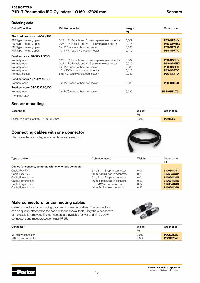
Connecting cables with one connectorThe cables have an integral snap-in female connector.
Description Weight Order code kg
Sensor mounting for P1D-T 160 - 320mm 0,040 PD48956
Sensor mounting
17
Seal Kits
Parker Hannifin CorporationPneumatic Division - Europe
PDE2667TCUK
P1D-T Pneumatic ISO Cylinders - Ø160 - Ø320 mm
Standard 4g tube KL8220
High temperature 4g tube KL8220
Grease for P1D-TP1D-T Seal Kits
Cyl.bore Standard High Temp. mm
160 PD23013 PD26995
200 PD25006 PD27427
250 PD25872 PD27976
320 PY00031 KL7325
Seal kit for bores Ø160 - Ø250 mm
Cyl.-dia Plastic piston T1 NV T2 NV mm Nm mm Nm mm
160 100 30 85 27 200 100 30 95 27 250 120 36 140 41
P1D-T Seal KitsComplete seal kits consisting of:Piston completeCushioning seals Piston rod bearing Scraper ringPiston rod seal O-rings
Material specification, see page 5
P1D-T Optional cylinder versions
Cyl.bore Through rod mm Standard temperature
160 P1D-6SRNF
200 P1D-6TRNF
250 P1D-6URNF
320 P1D-6VRNF
T1
T2= Included in seal kit = Lubricated with grease
= Socket head = Locking fluid
= Tighteningtorque = NutA/F
Loctite LT638 locking fluid must be used
For bore Ø320 please consult sales company
18
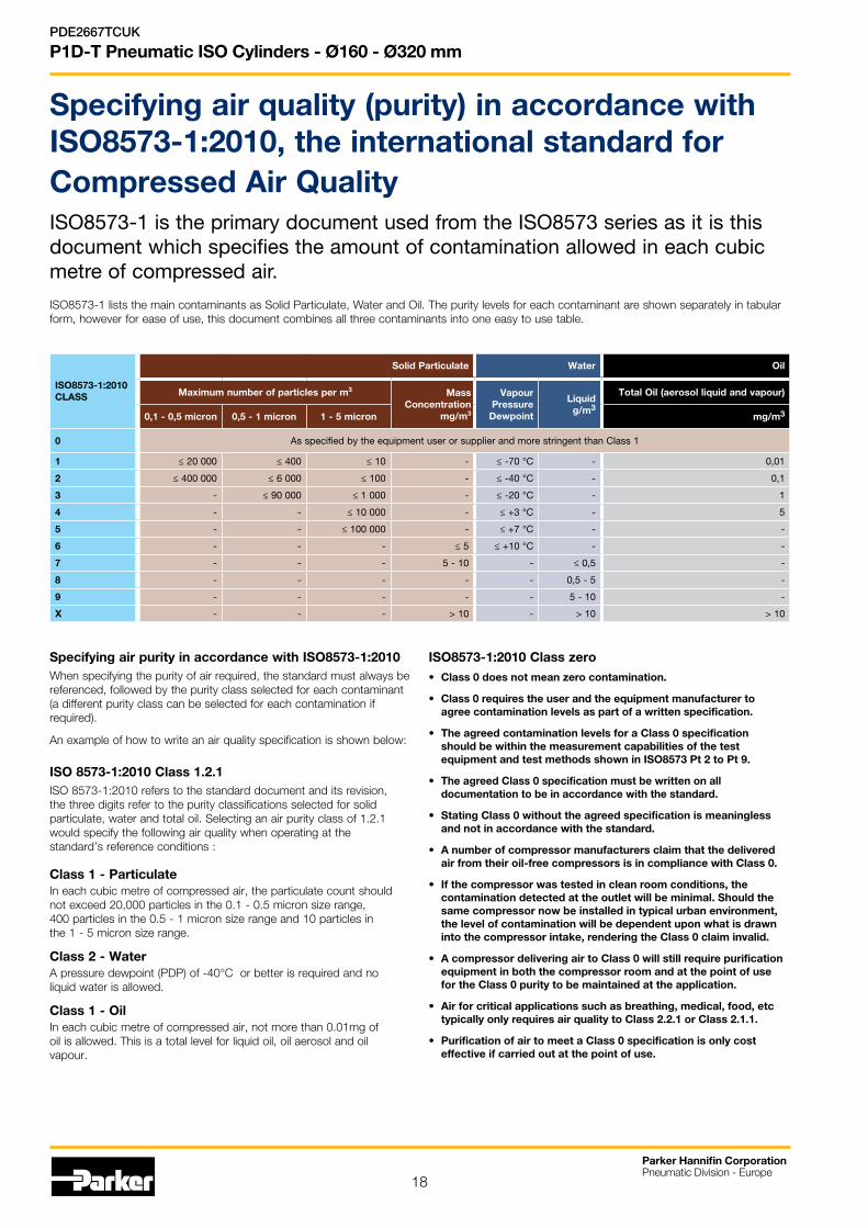
Specifying air quality (purity) in accordance with ISO8573-1:2010, the international standard for Compressed Air QualityISO8573-1 is the primary document used from the ISO8573 series as it is this document which specifies the amount of contamination allowed in each cubic metre of compressed air.
ISO8573-1 lists the main contaminants as Solid Particulate, Water and Oil. The purity levels for each contaminant are shown separately in tabular form, however for ease of use, this document combines all three contaminants into one easy to use table.
ISO8573-1:2010 CLASS
Solid Particulate Water Oil
Maximum number of particles per m3 MassConcentration
mg/m3
Vapour Pressure
Dewpoint
Liquid g/m3
Total Oil (aerosol liquid and vapour)
0,1 - 0,5 micron 0,5 - 1 micron 1 - 5 micron mg/m3
0 As specified by the equipment user or supplier and more stringent than Class 1
1 ≤ 20 000 ≤ 400 ≤ 10 - ≤ -70 °C - 0,01
2 ≤ 400 000 ≤ 6 000 ≤ 100 - ≤ -40 °C - 0,1
3 - ≤ 90 000 ≤ 1 000 - ≤ -20 °C - 1
4 - - ≤ 10 000 - ≤ +3 °C - 5
5 - - ≤ 100 000 - ≤ +7 °C - -
6 - - - ≤ 5 ≤ +10 °C - -
7 - - - 5 - 10 - ≤ 0,5 -
8 - - - - - 0,5 - 5 -
9 - - - - - 5 - 10 -
X - - - > 10 - > 10 > 10
Specifying air purity in accordance with ISO8573-1:2010When specifying the purity of air required, the standard must always be referenced, followed by the purity class selected for each contaminant (a different purity class can be selected for each contamination if required).
An example of how to write an air quality specification is shown below:
ISO 8573-1:2010 Class 1.2.1ISO 8573-1:2010 refers to the standard document and its revision, the three digits refer to the purity classifications selected for solid particulate, water and total oil. Selecting an air purity class of 1.2.1 would specify the following air quality when operating at the standard’s reference conditions :
Class 1 - ParticulateIn each cubic metre of compressed air, the particulate count should not exceed 20,000 particles in the 0.1 - 0.5 micron size range, 400 particles in the 0.5 - 1 micron size range and 10 particles in the 1 - 5 micron size range.
Class 2 - WaterA pressure dewpoint (PDP) of -40°C or better is required and no liquid water is allowed.
Class 1 - OilIn each cubic metre of compressed air, not more than 0.01mg of oil is allowed. This is a total level for liquid oil, oil aerosol and oil vapour.
ISO8573-1:2010 Class zero • Class0doesnotmeanzerocontamination.
• Class 0 requires the user and the equipment manufacturer to agree contamination levels as part of a written specification.
• TheagreedcontaminationlevelsforaClass0specificationshould be within the measurement capabilities of the test equipment and test methods shown in ISO8573 Pt 2 to Pt 9.
• The agreed Class 0 specification must be written on all documentation to be in accordance with the standard.
• StatingClass0withouttheagreedspecificationismeaninglessand not in accordance with the standard.
• Anumberofcompressormanufacturersclaimthatthedeliveredair from their oil-free compressors is in compliance with Class 0.
• Ifthecompressorwastestedincleanroomconditions,thecontamination detected at the outlet will be minimal. Should the same compressor now be installed in typical urban environment, the level of contamination will be dependent upon what is drawn into the compressor intake, rendering the Class 0 claim invalid.
• AcompressordeliveringairtoClass0willstillrequirepurificationequipment in both the compressor room and at the point of use for the Class 0 purity to be maintained at the application.
• Airforcriticalapplicationssuchasbreathing,medical,food,etctypically only requires air quality to Class 2.2.1 or Class 2.1.1.
• PurificationofairtomeetaClass0specificationisonlycosteffective if carried out at the point of use.
Parker Hannifin CorporationPneumatic Division - Europe
PDE2667TCUK
P1D-T Pneumatic ISO Cylinders - Ø160 - Ø320 mm
19
Parker Hannifin CorporationPneumatic Division - Europe
PDE2667TCUK
P1D-T Pneumatic ISO Cylinders - Ø160 - Ø320 mm
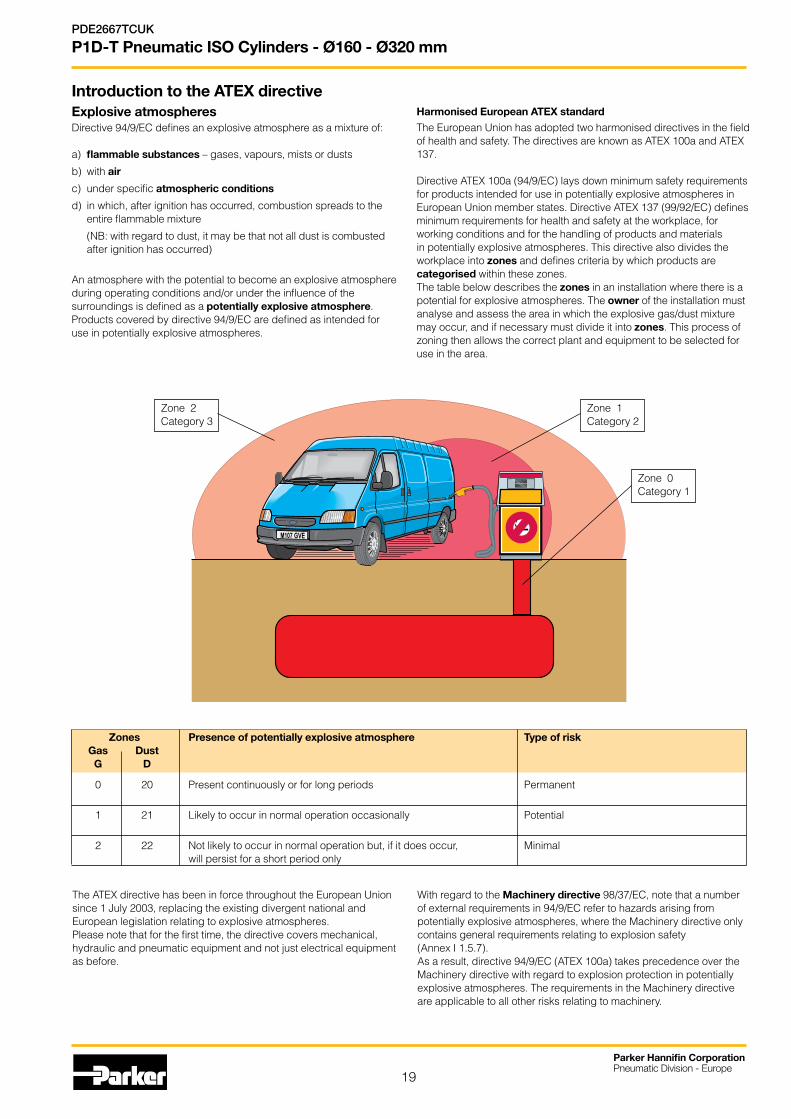
Introduction to the ATEX directiveExplosive atmospheresDirective 94/9/EC defines an explosive atmosphere as a mixture of:
a) flammable substances – gases, vapours, mists or dusts
b) with air
c) under specific atmospheric conditions
d) in which, after ignition has occurred, combustion spreads to the entire flammable mixture
(NB: with regard to dust, it may be that not all dust is combusted after ignition has occurred)
An atmosphere with the potential to become an explosive atmosphere during operating conditions and/or under the influence of the surroundings is defined as a potentially explosive atmosphere. Products covered by directive 94/9/EC are defined as intended for use in potentially explosive atmospheres.
Harmonised European ATEX standard
The European Union has adopted two harmonised directives in the field of health and safety. The directives are known as ATEX 100a and ATEX 137.
Directive ATEX 100a (94/9/EC) lays down minimum safety requirements for products intended for use in potentially explosive atmospheres in European Union member states. Directive ATEX 137 (99/92/EC) defines minimum requirements for health and safety at the workplace, for working conditions and for the handling of products and materials in potentially explosive atmospheres. This directive also divides the workplace into zones and defines criteria by which products are categorised within these zones. The table below describes the zones in an installation where there is a potential for explosive atmospheres. The owner of the installation must analyse and assess the area in which the explosive gas/dust mixture may occur, and if necessary must divide it into zones. This process of zoning then allows the correct plant and equipment to be selected for use in the area.
The ATEX directive has been in force throughout the European Union since 1 July 2003, replacing the existing divergent national and European legislation relating to explosive atmospheres.Please note that for the first time, the directive covers mechanical, hydraulic and pneumatic equipment and not just electrical equipment as before.
With regard to the Machinery directive 98/37/EC, note that a number of external requirements in 94/9/EC refer to hazards arising from potentially explosive atmospheres, where the Machinery directive only contains general requirements relating to explosion safety (Annex I 1.5.7).As a result, directive 94/9/EC (ATEX 100a) takes precedence over the Machinery directive with regard to explosion protection in potentially explosive atmospheres. The requirements in the Machinery directive are applicable to all other risks relating to machinery.
Zones Presence of potentially explosive atmosphere Type of risk Gas Dust G D
0 20 Present continuously or for long periods Permanent
1 21 Likely to occur in normal operation occasionally Potential
2 22 Not likely to occur in normal operation but, if it does occur, Minimal will persist for a short period only
Zone 1Category 2
Zone 2Category 3
Zone 0Category 1
20
Parker Hannifin CorporationPneumatic Division - Europe
PDE2667TCUK
P1D-T Pneumatic ISO Cylinders - Ø160 - Ø320 mm
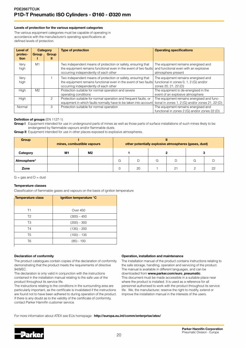
Temperature class Ignition temperature °C
T1 Over 450
T2 (300) – 450
T3 (200) – 300
T4 (135) – 200
T5 (100) – 135
T6 (85) - 100
Levels of protection for the various equipment categories
The various equipment categories must be capable of operating in accordance with the manufacturer’s operating specifications at defined levels of protection.
Level of Category Type of protection Operating specifications protec- Group Group tion I II
Very M1 Two independent means of protection or safety, ensuring that The equipment remains energised and high the equipment remains functional even in the event of two faults and functional even with an explosive occurring independently of each other atmosphere present
Very 1 Two independent means of protection or safety, ensuring that The equipment remains energised and high the equipment remains functional even in the event of two faults functional in zones 0, 1, 2 (G) and/or occurring independently of each other zones 20, 21, 22 (D) High M2 Protection suitable for normal operation and severe The equipment is de-energised in the operating conditions event of an explosive atmosphere High 2 Protection suitable for normal operation and frequent faults, or The equipment remains energised and func- equipment in which faults normally have to be taken into account tional in zones 1, 2 (G) and/or zones 21, 22 (D) Normal 3 Protection suitable for normal operation The equipment remains energised and functional in zones 2 (G) and/or zones 22 (D)
G = gas and D = dust
Temperature classes
Classification of flammable gases and vapours on the basis of ignition temperature
Group I II mines, combustible vapours other potentially explosive atmospheres (gases, dust)
Category M1 M2 1 2 3
Atmosphere* G D G D G D
Zone 0 20 1 21 2 22
Declaration of conformity
The product catalogues contain copies of the declaration of conformity demonstrating that the product meets the requirements of directive 94/9/EC.The declaration is only valid in conjunction with the instructions contained in the installation manual relating to the safe use of the product throughout its service life. The instructions relating to the conditions in the surrounding area are particularly important, as the certificate is invalidated if the instructions are found not to have been adhered to during operation of the product.If there is any doubt as to the validity of the certificate of conformity, contact Parker Hannifin customer service.
Operation, installation and maintenance
The installation manual of the product contains instructions relating to the safe storage, handling, operation and servicing of the product.The manual is available in different languages, and can be downloaded from www.parker.com/euro_pneumatic.This document must be made accessible in a suitable place near where the product is installed. It is used as a reference for all personnel authorised to work with the product throughout its service life. We, the manufacturer, reserve the right to modify, extend or improve the installation manual in the interests of the users.
For more information about ATEX see EUs homepage: http://europa.eu.int/comm/enterprise/atex/
Definition of groups (EN 1127-1)Group I Equipment intended for use in underground parts of mines as well as those parts of surface installations of such mines likely to be
endangered by flammable vapours and/or flammable dusts.Group II Equipment intended for use in other places exposed to explosive atmospheres.
21
Parker Hannifin CorporationPneumatic Division - Europe
PDE2667TCUK
P1D-T Pneumatic ISO Cylinders - Ø160 - Ø320 mm
Supplementary safety instructions for installation of ATEX certified P1S cylinders.The safety instructions in this document are valid for the ATEX certified P1D-T cylinders, bore 160 - 320mm, as per below with reference to the order code key in the product catalogue.
P1D-T***MS-****-EX
All strokes in the range 50 - 1000mm
Serious, even fatal, damage or injury may be caused by the hot moving parts of the P1D-T cylinders in the presence of explosive gas mixtures and concentrations of dust.
All installation, connection, commissioning, servicing and repair work on P1D-T cylinders must be carried out by qualified personnel taking account of the following
• Theseinstructions• Markingsonthecylinder• Allotherplanningdocuments,commissioninginstructionsand connection diagrams associated with the application.• Provisionsandrequirementsspecifictotheapplication• National/internationalregulations(explosionprotection,safetyand accident prevention)
Real life applicationsP1D-T cylinders are designed to provide linear movement in industrial applications, and should only be used in accordance with the instructions in the technical specifications in the catalogue, and within the operating range indicated on the rating plate.The cylinders meet the applicable standards and requirements of directive 94/9/EC (ATEX)
The cylinders must not be used underground in mines susceptible to firedamp and/or flammable dusts. The cylinders are intended for use in areas in which explosive atmospheres caused by gases, vapours or mists of flammable liquids, or air/dust mixtures may be expected to occur during normal use (infrequently)
Checklist
Before using the cylinders in an Ex-area, you should check thefollowing:Do the specifications of the P1D-T cylinder match the Ex-classification of the area of use in accordance with directive 94/9/EC (previously ATEX 100a)
•Equipmentgroup
•Ex-equipmentcategory
•Ex-zone
•Temperatureclass
•Max.surfacetemperature
1. When installing the P1D-T cylinder, is it certain that there is no potentially explosive atmosphere, oil, acids, gases, vapours or radiation?2. Is the ambient temperature as specified in the technical data in the catalogue at all times?3. Is it certain that the P1D-T cylinder is adequately ventilated and that no forbidden additional heat is added?4. Are all the driven mechanical components ATEX certified?5. Check that the P1D-T cylinder is safely earthed.6. Check that the P1D-T cylinder is supplied with compressed air. Explosive gas mixtures must not be used for driving the cylinder. 7. Check that the P1D-T cylinder is not equipped with a metal scraper ring (special version).
Installation requirements in Ex-areas• Thetemperatureofthesupplyairmustnotexceedtheambient
temperature.• TheP1D-Tcylindermaybeinstalledinanyposition.• TheP1D-Tcylindermustnotbeinstalledwherethereisariskof
mechanical contact with any surrounding part or component.• AnairtreatmentunitmustbeattachedtotheinletoftheP1D-T
cylinder.• TheP1D-Tcylindermustbeconnectedtoearthatalltimes,through
its support, a metallic tube or separate conductor.• TheoutletoftheP1D-TcylindermustnotbeopenwithinanEx-
area, but must be connected to the silencer or, preferably, piped and released outside the Ex-area.
• TheP1D-TcylindermayonlydriveunitsthatareATEXcertified.• EnsurethattheP1D-Tcylinderisnotexposedtoforcesgreaterthan
those permitted in accordance with the catalogue• TheP1D-Tcylindermustbesuppliedwithcompressedair.
Explosive gas mixtures must not be used• P1D-Tcylinderswithmetalscraperringsmustnotbeusedin
Ex-areas
Inspecting cylinders during operationThe P1D-T cylinder must be kept clean on the outside, and a layer of dust/dirt thicker than 1 mm must never be allowed to form.Inspect and verify that the cylinder, with attachments, compressed air fittings, hoses, tubes, etc. meet the standards of ”safe” installation.
Spare partsOnly spare parts, kits etc. supplied by Parker Hannifin may be used for repair and maintenance of the P1D-T cylinders.
Marking of ATEX certified P1D-T cylinders
The ATEX certified P1D-T cylinders, bore 160 - 320mm, as per below with reference to the order code key in the product catalogue have an ATEX certification marking as shown further below.
P1D-T***MS-****-EX
All strokes in the range 50 - 1000mm
Communauté Européenne = EU CE on the product shows that Parker Hannifin products meet
one or more EU directives Ex means that this product is intended for use in potentially
explosive atmospheresII Stands for the equipment group (I = mines and II = other
hazardous areas)2GD Stands for equipment category 2G means the equipment can
be used in zones 1 and 2 where there is a risk involving gases, vapours or mists of combustible liquids and 2D in zones 21 and 22 where there is a risk involving dusts. 2GD Means the equipment can be used in zones 1, 2, 21 and 22.
c Safe design (prEN 13463-5)T4 If equipment is in temperature class T4, the maximum surface
temperature must not exceed 135 °C. (To guarantee this, the product has been tested to ensure that the maximum is 130 °C. This provides a safety margin of 5 °K.)
120 °C Maximum permitted surface temperature on P1D-S cylinder in atmospheres containing potentially explosive dusts.
Safety instructions for the P1D-T cylinder with accessories
II 2GD c T4 120 °C
22
Parker Hannifin CorporationPneumatic Division - Europe
PDE2667TCUK
P1D-T Pneumatic ISO Cylinders - Ø160 - Ø320 mm
Supplementary safety instructions for P8S-GPFLX/EX sensors installed in Ex-areasSerious, even fatal, damage or injury may be caused by the hot moving parts of the P1D-T cylinders in the presence of explosive gas mixtures and concentrations of dust.
Instructions for use
Safety instructions
• CylindersensorATEXclassedforcategoryII3GandII3D
• AmbienttemperatureTa=-20°Cto+45°C
• TemperatureclassT4,ormax.surfacetemperatureofT=135°C
• ProtectionclassIP67
• Readinstallationinstructionsbeforestartup
• Installation,connectionandcommissioningmustbecarriedoutbytrained personnel
Applications
• ThissensorisdesignedforuseintheT-grooveofcylinders,anddetects the magnetic field in potentially explosive areas. The sensor can only be installed in the T-groove of these cylinders.
• Thesensormayalsobeinstalledonroundcylindersbymeansofthe following attachments:
P8S-TMC01 Suitable for P1S and P1A diameter 10 - 25 mm
P8S-TMC02 Suitable for P1S diameter 32 - 63 mm
P8S-TMC03 Suitable for P1S diameter 80 - 125 mm
The following data applies to these attachments:
- Ambient temperature Ta = 0 °C to 45 °C
- Low energy absorption to EN 50 021
• Thesensormayalsobeinstalledontie-rodcylindersorprofilecylinders by means of this attachment:
P8S-TMA0X Suitable for P1D-T diameter 32 - 125 mm, P1E-T diameter 160 – 200 mm and C41 diameter 160 – 200 mm
Installation
General: The sensor must be protected from UV radiation. The cable must be installed such that it is protected from external influences, for example it may be necessary to attach an external strain relief to the cable.
Technical data for sensor
Operating voltage Ub = 18 to 30 V DCMax. load current Ia 70mAAmbient temperature: -20 °C to 45 °C
Commissioning
When connecting the sensor to a power source, please pay attention to the followinga) the load data (operating voltage, continuous load current)b) the wiring diagram for the sensor
Maintenance
Our P8S-GPFLX/EX cylinder sensor is maintenance free, but the cable connections should be checked at regular intervals.The sensor must be protected from UV radiation. The sensor must be kept clean on the outside, and a layer of dirt thicker than 1 mm must never be allowed to form. Strong solvents should not be used for cleaning as they may damage the sensor.
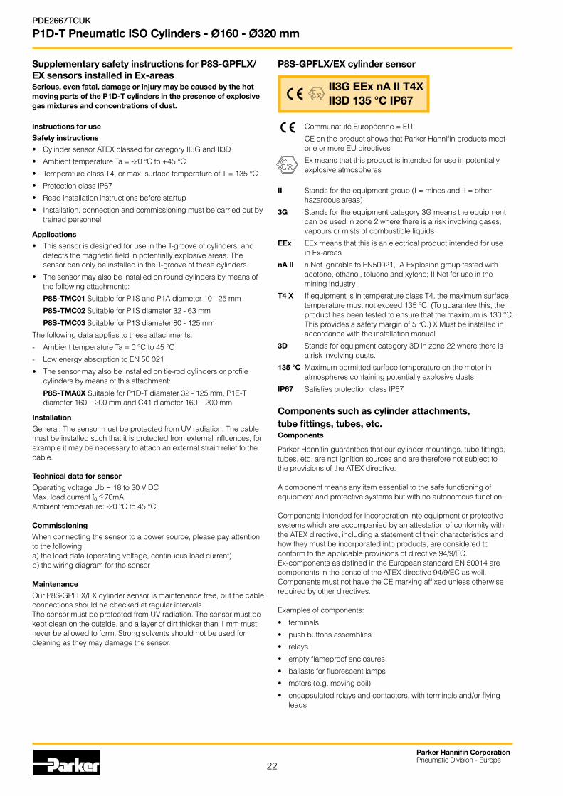
P8S-GPFLX/EX cylinder sensor
Communatuté Européenne = EU
CE on the product shows that Parker Hannifin products meet one or more EU directives
Ex means that this product is intended for use in potentially explosive atmospheres
II Stands for the equipment group (I = mines and II = otherhazardous areas)
3G Stands for the equipment category 3G means the equipment can be used in zone 2 where there is a risk involving gases, vapours or mists of combustible liquids
EEx EEx means that this is an electrical product intended for use in Ex-areas
nA II n Not ignitable to EN50021, A Explosion group tested with acetone, ethanol, toluene and xylene; II Not for use in the mining industry
T4 X If equipment is in temperature class T4, the maximum surface temperature must not exceed 135 °C. (To guarantee this, the product has been tested to ensure that the maximum is 130 °C. This provides a safety margin of 5 °C.) X Must be installed in accordance with the installation manual
3D Stands for equipment category 3D in zone 22 where there is a risk involving dusts.
135 °C Maximum permitted surface temperature on the motor in atmospheres containing potentially explosive dusts.
IP67 Satisfies protection class IP67
Components such as cylinder attachments, tube fittings, tubes, etc.Components
Parker Hannifin guarantees that our cylinder mountings, tube fittings, tubes, etc. are not ignition sources and are therefore not subject to the provisions of the ATEX directive.
A component means any item essential to the safe functioning of equipment and protective systems but with no autonomous function.
Components intended for incorporation into equipment or protective systems which are accompanied by an attestation of conformity with the ATEX directive, including a statement of their characteristics and how they must be incorporated into products, are considered to conform to the applicable provisions of directive 94/9/EC. Ex-components as defined in the European standard EN 50014 are components in the sense of the ATEX directive 94/9/EC as well. Components must not have the CE marking affixed unless otherwise required by other directives.
Examples of components:
• terminals
• pushbuttonsassemblies
• relays
• emptyflameproofenclosures
• ballastsforfluorescentlamps
• meters(e.g.movingcoil)
• encapsulatedrelaysandcontactors,withterminalsand/orflyingleads
II3G EEx nA II T4X II3D 135 °C IP67
<_

23
Parker Hannifin CorporationPneumatic Division - Europe
PDE2667TCUK
P1D-T Pneumatic ISO Cylinders - Ø160 - Ø320 mm

Your local authorized Parker distributor
Catalogue PDE2667TCUK July 2012© 2012 Parker Hannifin Corporation. All rights reserved.
Parker Worldwide
Parker Hannifin Ltd.Tachbrook Park DriveTachbrook Park, Warwick, CV34 6TUUnited Kingdom Tel.: +44 (0) 1926 317 878 Fax: +44 (0) 1926 317 [email protected]
European Product Information Centre
Free phone: 00 800 27 27 5374
(from AT, BE, CH, CZ, DE, DK, EE, ES, FI,
FR, IE, IL, IS, IT, LU, MT, NL, NO, PL, PT, RU,
SE, SK, UK, ZA)
Europe, Middle East, AfricaAE – United Arab Emirates, Dubai Tel: +971 4 8127100 [email protected]
AT – Austria, Wiener NeustadtTel: +43 (0)2622 23501-0 [email protected]
AT – Eastern Europe, Wiener Neustadt Tel: +43 (0)2622 23501 900 [email protected]
AZ – Azerbaijan, BakuTel: +994 50 2233 458 [email protected]
BE/LU – Belgium, NivellesTel: +32 (0)67 280 900 [email protected]
BY – Belarus, MinskTel: +375 17 209 9399 [email protected]
CH – Switzerland, EtoyTel: +41 (0)21 821 87 00 [email protected]
CZ – Czech Republic, KlecanyTel: +420 284 083 111 [email protected]
DE – Germany, KaarstTel: +49 (0)2131 4016 0 [email protected]
DK – Denmark, BallerupTel: +45 43 56 04 00 [email protected]
ES – Spain, MadridTel: +34 902 330 001 [email protected]
FI – Finland, VantaaTel: +358 (0)20 753 2500 [email protected]
FR – France, Contamine s/ArveTel: +33 (0)4 50 25 80 25 [email protected]
GR – Greece, AthensTel: +30 210 933 6450 [email protected]
HU – Hungary, BudapestTel: +36 23 885 475 [email protected]
IE – Ireland, DublinTel: +353 (0)1 466 6370 [email protected]
IT – Italy, Corsico (MI)Tel: +39 02 45 19 21 [email protected]
KZ – Kazakhstan, AlmatyTel: +7 7272 505 800 [email protected]
NL – The Netherlands, OldenzaalTel: +31 (0)541 585 000 [email protected]
NO – Norway, AskerTel: +47 66 75 34 00 [email protected]
PL – Poland, WarsawTel: +48 (0)22 573 24 00 [email protected]
PT – Portugal, Leca da PalmeiraTel: +351 22 999 7360 [email protected]
RO – Romania, BucharestTel: +40 21 252 1382 [email protected]
RU – Russia, MoscowTel: +7 495 645-2156 [email protected]
SE – Sweden, SpångaTel: +46 (0)8 59 79 50 00 [email protected]
SK – Slovakia, Banská BystricaTel: +421 484 162 252 [email protected]
SL – Slovenia, Novo MestoTel: +386 7 337 6650 [email protected]
TR – Turkey, IstanbulTel: +90 216 4997081 [email protected]
UA – Ukraine, KievTel +380 44 494 2731 [email protected]
UK – United Kingdom, WarwickTel: +44 (0)1926 317 878 [email protected]
ZA – South Africa, Kempton ParkTel: +27 (0)11 961 0700 [email protected]
North AmericaCA – Canada, Milton, OntarioTel: +1 905 693 3000
US – USA, Cleveland Tel: +1 216 896 3000
Asia PacificAU – Australia, Castle HillTel: +61 (0)2-9634 7777
CN – China, ShanghaiTel: +86 21 2899 5000
HK – Hong Kong Tel: +852 2428 8008
IN – India, MumbaiTel: +91 22 6513 7081-85
JP – Japan, TokyoTel: +81 (0)3 6408 3901
KR – South Korea, SeoulTel: +82 2 559 0400
MY – Malaysia, Shah AlamTel: +60 3 7849 0800
NZ – New Zealand, Mt WellingtonTel: +64 9 574 1744
SG – Singapore Tel: +65 6887 6300
TH – Thailand, BangkokTel: +662 186 7000-99
TW – Taiwan, TaipeiTel: +886 2 2298 8987
South AmericaAR – Argentina, Buenos AiresTel: +54 3327 44 4129
BR – Brazil, Sao Jose dos CamposTel: +55 800 727 5374
CL – Chile, SantiagoTel: +56 2 623 1216
MX – Mexico, ApodacaTel: +52 81 8156 6000