Embed Size (px)
Citation preview
Pneumatic Products
»

»
The benefits of an innovative, pneumatic coupling
design were solid enough to single-handedly launch
CEJN in 1955.
This reliable, easy-to-handle coupling replaced
cumbersome and undependable compressed air
couplings of the era and has remained a staple for
customers around the world.
That original quick connect coupling keeps good
company at CEJN. CEJN’s strategy to provide what
customers value most has enabled the company
to offer numerous series of couplings that fill
specific needs, as well as hose, hose kits, hose and
cable reels, blowguns, air treatment products, and
accessories.
Supported by global, ISO 9001-certified assembly
and testing operations, CEJN products are
manufactured to meet stringent functionality and
quality requirements and are rigorously tested to
ensure they can perform the tasks set before them.
No products are better suited to compressed air
applications than CEJN pneumatic products. Each
product benefits from a well-planned, well-made
approach that makes it an industry standout.
Industry Standouts for Over 50 Years
CEJN reserves the right to make product changes without further notification.

8
54
65
67
33
38
47
51
28
30
26
$£ € 4
»
75
CEJN Pneumatics Products
Cost-saving Benefits
Couplings
Soft-Line Couplings
Aluminum Couplings
Multi-Link System
Hose Kits
Hose
Hose And Cable Reels
Blowguns
FRL Products
Complementary Products
Safety Products
Facts and Figures

$ £€
4
Cos
t-sa
ving
Ben
efits
One of the major costs in manufacturing environments is compressed air. Optimization of compressed air systems can have a major impact on controlling costs for this on-site generated energy source.
The most common causes of energy loss in compressed air systems are leaks and pressure drop.
Leaks can be a leading source of wasted energy in compressed air systems. They can cause a drop in system pressure and shorten the life of nearly all system components.
Pressure drop leads to insufficient power for tools. Efficiency losses on tools lead to longer work cycles and higher production costs result.
CEJN pneumatic couplings are specially designed to address the primary causes of energy loss in compressed air systems through well-planned features. In turn, CEJN couplings result in significant reduction in energy consumption.
In addition to energy costs, CEJN couplings also address such problems as safety concerns, shortened component life, and high maintenance costs.
Delivering Cost-saving Benefits through Well-planned Features
Cost-saving Benefits
Air LeakageHole diameter – Volume of leaking air at 8 bar
1 mm 75 l/min
3 mm 600 l/min
5 mm 1700 l/min

$ £€
5
Cos
t-sa
ving
Ben
efits
Easy To Handle
Pre-applied thread sealant Results in quick, easy, and air-tight installation
Low connection force Minimizes operator exertion and eliminates fatigue
One-hand operation Allows fast, easy, and secure connection and disconnection
High flow Allows improved tool performance
High Efficiency
Air-tight design Prevents air loss during connection and operation
Hardened steel nipple bodies and locking sleeves Offer maximum wearing strength and lengthy, uninterrupted service life
Close tolerancesEnsure smooth, efficient operation time after time
Smooth machined partsMake sure mating parts are always properly aligned, ensuring air tightness
Pre-lubricated locking ballsPrevent premature wear and provide improved vibration resistance
Long Life
Extremely low pressure dropPermits lower energy consumption
Exposed surfaces are chrome-, nickel-, or zinc-platedEnsures resistance to corrosion and protection in harsh environments
Ergonomically designed sleeve Provides a more secure grip and prevents slippage

$ £€
6
1 2 3 4 5 6 7
Cos
t-sa
ving
Ben
efits
Unique Valve Construction Adds to Superior Performance of CEJN Pneumatic Couplings
Numerous construction features make the CEJN valve unique:
1. Aerodynamic, conical-shaped valve Air is allowed to flow into the valve
without undue turbulence, resulting in less pressure drop and higher flow.
2. Extra-large, aerodynamic-shaped ports Air flow is enhanced, resulting in less pressure
drop and higher flow.
3. Smooth, linear flow angles Instability and drag are eliminated, resulting
in less pressure drop and higher flow.
4. Valve spring located outside the flow path A major obstruction to flow is eliminated,
resulting in less pressure drop and higher flow.
5. Nipple goes into the valve The circumference of the nipple is sealed
with an O-ring inside the valve, preventing leaks due to side loads and misalignment.
6. Minimal pressure area Less surface area of the valve is exposed
to pressure, resulting in lower connection force.
7. Hardened steel nipple machined to precise specifications
Properly opened valve and larger inside diameter result in less pressure drop and higher flow.

$ £€
7
7.00 / 101.56.96 / 100.96.92 / 100.36.88 / 99.86.84 / 99.26.80 / 98.66.76 / 98.06.72 / 97.46.68 / 96.86.64 / 96.36.60 / 95.7
Cos
t-sa
ving
Ben
efits
CEJN COUPLINg
BRANd X COUPLINg
Extremely high pressure drop Caused by a valve that is flat with very sharp edges and severe flow angles
Excessive restrictions to flow Caused by a spring in the flow path and very small valve ports, as well as nipples with small inside diameters
Leaks Caused by metal-to-metal contact between the valve and nipple
High connection force Caused by excessive surface area exposed to pressure
Short coupling service life Caused by less durable, brass nipples that are prone to wear and tear
The smart design of CEJN couplings overcomes common problems associated with conventional couplings, such as:
Pressure (bar/PSI)

10
1:1
300Cou
plin
gs
Flow capacity is measured at 6 bar (87 PSI) inlet pressure, and pressure drop at 0.5 bar (7 PSI). Thread connections are listed according to ISO Standards (see Page 78 for more information). Check with an authorized CEJN distributor for availability and prices.
• Full automatic operation • Strong and durable • High flow capacity
Series 300 couplings offer high flow and require only a low connection force, which ensures a safe working environment. Male threads on the couplings and nipples feature pre-applied thread sealant.
The Series 300 vented safety version is disconnected in two stages in order to vent the coupling and minimize the risk of sudden component separation, which has the potential to cause operator injury. FuIl automatic operation ensures easy handling. The vented safety version complies with ISO Standard 4414 and EN 983.
5.5 mm (7/32”)1050 l/min. (37.1 CFM)16 bar (232 PSI)140 bar (2030 PSI)-20°C to +100°C (-4°F to +212°F)Zinc-plated steel/brassHardened zinc-plated steel 70.7 N
Technical dataNominal flow dia. ..........................Flow capacity ................................Max. working pressure ................Min. burst pressure ......................Temperature range .......................Coupling Material .........................Nipple Material ..............................Connection force ..........................
Pre
ssur
e dr
op, b
ar (P
SI)
Flow, liters/min. (CFM)
Air Flow
Pre
ssur
e dr
op, b
ar (P
SI)
Flow, liters/min. (CFM)
Air Flow
5.5 mm (7/32”)975 l/min. (34.4 CFM)12 bar (174 PSI)48 bar (696 PSI)-20°C to +80°C (-4°F to +176°F)Zinc-plated steel/brass59.8 N
Technical dataNominal flow dia. ..........................Flow capacity ................................Max. working pressure ................Min. burst pressure ......................Temperature range .......................Coupling Material .........................Connection force ..........................
Series 300 – Standard & Vented SafetyARO 210 STANdARd bENELux, NORTH AMERICA, SwITZERLANd
STANdARd
VENTEd SAFETY
This series includes safety products. For other safety products, see Page 67-74.

11300
1:1
10 300 8003 8 mm (5/16") 10 300 8004 10 mm (3/8")
10 300 8060 6 x10 mm 10 300 8062 8 x12 mm
10 300 3002 6.3 mm (1/4”) 10 300 3003 8 mm (5/16”) 10 300 3004 10 mm (3/8”) 10 300 3005 13 mm (1/2”)10 300 3152 R 1/4” 10 300 3154 R 3/8” 10 300 3155 R 1/2” 10 300 3452 NPT 1/4" 10 300 3454 NPT 3/8" 10 300 3455 NPT 1/2" 10 300 3202 G 1/4” 10 300 3204 G 3/8” 10 300 3205 G 1/2” 10 300 3402 NPT 1/4" 10 300 3404 NPT 3/8" 10 300 3405 NPT 1/2"10 300 3060 6.5 x 10 mm 10 300 3062 8 x 12 mm 10 300 3063 9.5 x 13.5 mm 10 300 3066 11 x 16 mm10 300 3080 6.5 x 10 mm 10 300 3082 8 x 12 mm
10 300 5002 6.3 mm (1/4") 10 300 5003 8 mm (5/16") 10 300 5004 10 mm (3/8")10 300 5151 R 1/8" 10 300 5152 R 1/4" 10 300 5154 R 3/8" 10 300 5155 R 1/2" 10 300 5451 NPT 1/8" 10 300 5452 NPT 1/4" 10 300 5454 NPT 3/8"10 300 5201 G 1/8" 10 300 5202 G 1/4" 10 300 5204 G 3/8" 10 300 5401 NPT 1/8" 10 300 5402 NPT 1/4" 10 300 5404 NPT 3/8"10 300 5058 5 x 8 mm 10 300 5060 6.5 x 10 mm 10 300 5062 8 x 12 mm 10 300 5063 9.5 x 13.5 mm 10 300 5066 11 x 16 mm
19 902 1061
19 902 2061 G 1/2" 19 902 2066 NPT 1/2"
10 300 1002 6.3 mm (1/4”) 10 300 1003 8 mm (5/16”) 10 300 1004 10 mm (3/8”)
10 300 1152 R 1/4” 10 300 1154 R 3/8” 10 300 1155 R 1/2” 10 300 1452 NPT 1/4"10 300 1202 G 1/4” 10 300 1204 G 3/8” 10 300 1402 NPT 1/4"
10 300 1060 6.5 x 10 mm 10 300 1062 8 x 12 mm
Cou
plin
gs
Series 300 – Standard & Vented SafetyARO 210 STANdARd
Hose connection
Male thread
Female thread
Stream-Line connection
Soft-Line Stream-Line connection (Page 26)
Part No. Connection
Hose connection
Male thread
Female thread
Stream-Line connection
Part No. Connection
NIPPLES
VENTEd SAFETY COUPLINgS
Center module, Vented Safety
Outlet module, Vented Safety
Part No. ConnectionMULTI-LINK (Page 30)
Hose connection
Stream-Line connection
Part No. ConnectionANTI-HOSE WHIP NIPPLES
Hose connection
Male thread
Female thread
Stream-Line connection
Part No. ConnectionCOUPLINgS
Flow capacity is measured at 6 bar (87 PSI) inlet pressure, and pressure drop at 0.5 bar (7 PSI). Thread connections are listed according to ISO Standards (see Page 78 for more information). Check with an authorized CEJN distributor for availability and prices.
This series includes safety products. For other safety products, see Page 67-74.

13
1:1
310 Cou
plin
gs
Pre
ssur
e dr
op, b
ar (P
SI)
Flow, liters/min. (CFM)
Air Flow
Flow capacity is measured at 6 bar (87 PSI) inlet pressure, and pressure drop at 0.5 bar (7 PSI). Thread connections are listed according to ISO Standards (see Page 78 for more information). Check with an authorized CEJN distributor for availability and prices.
• High flow capacity • One-hand operation• Low connection force
5.3 mm (7/32")925 l/min. (32.7 CFM)16 bar (232 PSI)140 bar (2030 PSI)-20°C – +100°C (-4°F – +212°F)Zinc-plated steel/brassHardened zinc-plated steel70.7 N
Technical dataNominal flow dia. ....................Flow capacity ..........................Max. working pressure ..........Min. burst pressure ................Temperature range .................Coupling Material ...................Nipple Material ........................Connection force ....................
Series 310 offers a wide range of easy-to-grip couplings, including Soft-Line, Stream-Line, and Multi-Link connections. Male threads on the couplings and nipples feature pre-applied thread sealant.
The Series 310 vented safety version is disconnected in two stages in order to vent the coupling and minimize the risk of sudden component separation, which has the potential to cause operator injury. FuIl automatic operation ensures easy handling. The vented safety version complies with ISO Standard 4414 and EN 983.
Pre
ssur
e dr
op, b
ar (P
SI)
Flow, liters/min. (CFM)
Air Flow
5.3 mm (7/32”)900 l/min. (31.8 CFM)12 bar (174 PSI)48 bar (696 PSI)-20°C – +80°C (-4°F – +176°F)Zinc-plated steel/brass61.7 N
Technical dataNominal flow dia. ....................Flow capacity ..........................Max. working pressure ..........Min. burst pressure ................Temperature range .................Coupling Material ...................Connection force ....................
Series 310 – Standard & Vented SafetyA-A 59439 (former U.S. Standard MIL C 4109 1/4"), ISO 6150 BbENELux, FRANCE, NORTH AMERICA, NORwAy, SwITZERLANd
This series includes safety products. For other safety products, see Page 67-74.
STANdARd
VENTEd SAFETY

14310
1:1
10 310 1002 6.3 mm (1/4'') 10 310 1003 8 mm (5/16'') 10 310 1004 10 mm (3/8'') 10 310 1005 13 mm (1/2'')
10 310 1152 R 1/4'' 10 310 1154 R 3/8'' 10 310 1155 R 1/2'' 10 310 1452 NPT 1/4'' 10 310 1454 NPT 3/8'' 10 310 1455 NPT 1/2''10 310 1202 G 1/4'' 10 310 1204 G 3/8'' 10 310 1205 G 1/2'' 10 310 1402 NPT 1/4'' 10 310 1404 NPT 3/8'' 10 310 1405 NPT 1/2''10 310 1058 5 x 8 mm 10 310 1060 6.5 x 10 mm 10 310 1062 8 x 12 mm 10 310 1063 9.5 x 13.5 mm 10 310 1066 11 x 16 mm10 310 1042 1/4" 10 310 1044 3/8" 10 310 1045 1/2"
10 310 1083 6.5 x10 mm 10 310 1084 8 x 12 mm10 310 1240 G 1/4" 10 310 1241 G 3/8" 10 310 1446 NPT 1/4" 10 310 1447 NPT 3/8"
10 310 5001 5 mm (3/16'') 10 310 5002 6.3 mm (1/4'') 10 310 5003 8 mm (5/16'') 10 310 5004 10 mm (3/8'') 10 310 5005 13 mm (1/2'')10 310 5151 R 1/8'' 10 310 5152 R 1/4'' 10 310 5154 R 3/8'' 10 310 5252 G 1/4" 10 310 5451 NPT 1/8'' 10 310 5452 NPT 1/4'' 10 310 5454 NPT 3/8'' 10 310 5455 NPT 1/2"10 310 5201 G 1/8'' 10 310 5202 G 1/4'' 10 310 5204 G 3/8'' 10 310 5401 NPT 1/8'' 10 310 5402 NPT 1/4'' 10 310 5404 NPT 3/8''10 310 5058 5 x 8 mm 10 310 5060 6.5 x 10 mm 10 310 5062 8 x 12 mm 10 310 5063 9.5 x 13.5 mm 10 310 5066 11 x 16 mm10 310 5042 1/4" 10 310 5044 3/8" 10 310 5045 1/2"
10 310 3002 6.3 mm (1/4”) 10 310 3003 8 mm (5/16”) 10 310 3004 10 mm (3/8”) 10 310 3005 13 mm (1/2”)10 310 3152 R 1/4” 10 310 3154 R 3/8” 10 310 3155 R 1/2” 10 310 3452 NPT 1/4” 10 310 3454 NPT 3/8” 10 310 3455 NPT 1/2” 10 310 3202 G 1/4” 10 310 3204 G 3/8” 10 310 3205 G 1/2” 10 310 3402 NPT 1/4” 10 310 3404 NPT 3/8” 10 310 3405 NPT 1/2” 10 310 3060 6.5 x 10 mm 10 310 3062 8 x 12 mm 10 310 3063 9.5 x 13.5 mm
10 310 3080 6.5 x 10 mm 10 310 3082 8 x 12 mm10 310 3234 G 3/8"
19 902 1070
19 902 2070 G 1/2" 19 902 2075 NPT 1/2"
19 902 1071
19 902 2071 G 1/2" 19 902 2076 NPT 1/2"
10 310 8003 8 mm (5/16") 10 310 8004 10 mm (3/8")
10 310 8060 6.5 x 10 mm 10 310 8062 8 x 12 mm
Cou
plin
gs
Center module
Outlet module
Center module, Vented Safety
Outlet module, Vented Safety
Flow capacity is measured at 6 bar (87 PSI) inlet pressure, and pressure drop at 0.5 bar (7 PSI). Thread connections are listed according to ISO Standards (see Page 78 for more information). Check with an authorized CEJN distributor for availability and prices.
Hose connection
Male thread
Female thread
Stream-Line connection
CEJN-Lock hose connection
Soft-Line Stream-Line connection (Page 26) Female thread
Part No. Connection
Hose connection
Male thread
Female thread
Stream-Line connection
CEJN-Lock hose connection
Part No. Connection
NIPPLES
COUPLINgS
Hose connection
Male thread
Female thread
Stream-Line connection
Soft-Line Stream-Line connection (Page 26) Female thread
Part No. ConnectionVENTEd SAFETY COUPLINgS
Part No. ConnectionMULTI-LINK (page 30)
Hose connection
Stream-Line connection
Part No. ConnectionANTI-HOSE WHIP NIPPLES
Series 310 – Standard & Vented SafetyA-A 59439 (former U.S. Standard MIL C 4109 1/4"), ISO 6150 B
This series includes safety products. For other safety products, see Page 67-74.

15
1:1
31510 315 1002 6.3 mm (1/4") 10 315 1043 7 mm (9/32”) 10 315 1004 10 mm (3/8”) 10 315 1005 13 mm (1/2”)10 315 1152 R 1/4” 10 315 1154 R 3/8” 10 315 1155 R 1/2” 10 315 1452 NPT 1/4” 10 315 1454 NPT 3/8” 10 315 1455 NPT 1/2”10 315 1102 Rc 1/4” 10 315 1104 Rc 3/8” 10 315 1105 Rc 1/2” 10 315 1402 NPT 1/4” 10 315 1404 NPT 3/8” 10 315 1405 NPT 1/2”10 315 1058 5 x 8 mm 10 315 1060 6.5 x 10 mm 10 315 1062 8 x 12 mm 10 315 1066 11 x1 6 mm
10 315 5101 Rc 1/8” 10 315 5102 Rc 1/4” 10 315 5104 Rc 3/8” 10 315 5105 Rc 1/2” 10 315 5402 NPT 1/4" 10 315 5404 NPT 3/8" 10 315 5405 NPT 1/2"10 315 5058 5 x 8 mm 10 315 5060 6.5 x 10 mm 10 315 5062 8 x 12 mm 10 315 5066 11 x 16 mm10 315 5085 6.5 x 10 mm 10 315 5086 8 x 12 mm
10 315 5001 5 mm (3/16”) 10 315 5002 6.3 mm (1/4”) 10 315 5043 7 mm (9/32”) 10 315 5004 10 mm (3/8”) 10 315 5005 13 mm (1/2”)10 315 5151 R 1/8” 10 315 5152 R 1/4” 10 315 5154 R 3/8” 10 315 5155 R 1/2” 10 315 5452 NPT 1/4" 10 315 5454 NPT 3/8" 10 315 5455 NPT 1/2"
10 315 8012 6.3 mm (1/4”) 10 315 8013 7 mm (9/32”) 10 315 8014 10 mm (3/8”) 10 315 8015 13 mm (1/2”)10 315 8152 R 1/4” 10 315 8154 R 3/8” 10 315 8452 NPT 1/4”
10 315 8102 Rc 1/4” 10 315 8402 NPT 1/4”
10 315 8068 5 x 8 mm 10 315 8070 6.5 x 10 mm 10 315 8072 8 x 12 mm 10 315 8076 11 x 16 mm
Cou
plin
gs
Hose connection
Male thread
Female thread
Stream-Line connection
Part No. Connection
Pre
ssur
e dr
op, b
ar (P
SI)
Flow, liters/min. (CFM)
Female thread
Stream-Line connection
Stream-Line connection with kink protector
Part No. Connection NIPPLESCOUPLINgS
Air Flow
Hose connection
Male thread
Female thread
Stream-Line connection
Part No. ConnectionANTI-HOSE WHIP NIPPLES
Flow capacity is measured at 6 bar (87 PSI) inlet pressure, and pressure drop at 0.5 bar (7 PSI). Thread connections are listed according to ISO Standards (see Page 78 for more information). Check with an authorized CEJN distributor for availability and prices.
• Extremely high flow capacity • Low connection force• One-hand operation
7.5 mm (5/16”)1950 l/min. (68.9 CFM)16 bar (232 PSI)140 bar (2030 PSI)-20°C to +100°C (-4°F to +212°F)Zinc-plated steel/brassHardened zinc-plated steel 73.5 N
Technical dataNominal flow dia. ..........................Flow capacity ................................Max. working pressure ................Min. burst pressure ......................Temperature range .......................Coupling Material .........................Nipple Material ..............................Connection force ..........................
Series 315 couplings are lightweight and easy to handle, yet strong and durable. The series includes a wide range of connections, as well as anti-hose whip nipples. Male threads on the couplings and nipples feature pre-applied thread sealant.
Part No. Connection
Hose connection
Male thread
NIPPLES
This series includes safety products. For other safety products, see Page 67-74.
Series 315 – StandardASIAN STANdARdASIA, ITALy, SOuTH AMERICA

16
1:1
320Cou
plin
gs
Pre
ssur
e dr
op, b
ar (P
SI)
Flow, liters/min. (CFM)
Air Flow
Pre
ssur
e dr
op, b
ar (P
SI)
Flow, liters/min. (CFM)
Air Flow
Flow capacity is measured at 6 bar (87 PSI) inlet pressure, and pressure drop at 0.5 bar (7 PSI). Thread connections are listed according to ISO Standards (see Page 78 for more information). Check with an authorized CEJN distributor for availability and prices.
• Extremely high flow capacity • Easy to connect • Strong and durable
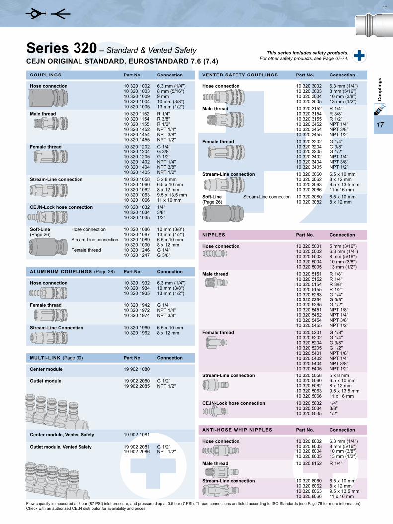
Series 320 couplings feature the original high-flow valve design upon which all other CEJN pneumatic couplings are based. Their popularity has made Series 320 a European standard. The series is easy-to-handle and one-hand operated and offers long service life. Male threads on the couplings and nipples feature pre-applied thread sealant. Lightweight aluminum styles are also available (also see the Aluminum Couplings section of this catalog).
The Series 320 vented safety version is disconnected in two stages in order to vent the coupling and minimize the risk of sudden component separation, which has the potential to cause operator injury. FuIl automatic operation ensures easy handling. The vented safety version complies with ISO Standard 4414 and EN 983.
Refer to the CEJN Fluid Products Catalog for specialized versions of Series 320 with brass nipples (Series 321), high-pressure straight-through design (Series 322), two-way shutoff (Series 324), and stainless steel construction (Series 326).
7.6 mm (5/16”)2100 l/min. (74.2 CFM)16 bar (232 PSI)140 bar (2030 PSI)-20°C to +100°C (-4°F to +212°F)Zinc-plated steel/brassHardened zinc-plated steel70.7 N
Technical dataNominal flow dia. ..........................Flow capacity. ...............................Max. working pressure ................Min. burst pressure ......................Temperature range .......................Coupling Material .........................Nipple Material ..............................Connection force. .........................
7.6 mm (5/16”)1900 l/min. (67.1 CFM)12 bar (174 PSI)48 bar (696 PSI)-20°C to +80°C (-4°F to +176°F)Zinc-plated steel/brass64.0 N
Technical dataNominal flow dia. ..........................Flow capacity. ...............................Max. working pressure ................Min. burst pressure ......................Temperature range .......................Coupling Material .........................Connection force. .........................
Series 320 – Standard & Vented SafetyCEJN ORIgINAL STANdARd, EUROSTANdARd 7.6 (7.4)GLObAL
This series includes safety products. For other safety products, see Page 67-74.
STANdARd
VENTEd SAFETY
17
3201:1
10 320 8002 6.3 mm (1/4") 10 320 8003 8 mm (5/16") 10 320 8004 10 mm (3/8") 10 320 8005 13 mm (1/2")10 320 8152 R 1/4"
10 320 8060 6.5 x 10 mm 10 320 8062 8 x 12 mm 10 320 8063 9.5 x 13.5 mm 10 320 8066 11 x 16 mm
10 320 5001 5 mm (3/16'') 10 320 5002 6.3 mm (1/4'') 10 320 5003 8 mm (5/16'') 10 320 5004 10 mm (3/8'') 10 320 5005 13 mm (1/2'')10 320 5151 R 1/8'' 10 320 5152 R 1/4'' 10 320 5154 R 3/8'' 10 320 5155 R 1/2'' 10 320 5263 G 1/4" 10 320 5264 G 3/8" 10 320 5265 G 1/2" 10 320 5451 NPT 1/8" 10 320 5452 NPT 1/4" 10 320 5454 NPT 3/8" 10 320 5455 NPT 1/2"10 320 5201 G 1/8'' 10 320 5202 G 1/4'' 10 320 5204 G 3/8'' 10 320 5205 G 1/2'' 10 320 5401 NPT 1/8" 10 320 5402 NPT 1/4" 10 320 5404 NPT 3/8" 10 320 5405 NPT 1/2"10 320 5058 5 x 8 mm 10 320 5060 6.5 x 10 mm 10 320 5062 8 x 12 mm 10 320 5063 9.5 x 13.5 mm 10 320 5066 11 x 16 mm10 320 5032 1/4" 10 320 5034 3/8" 10 320 5035 1/2"
10 320 1002 6.3 mm (1/4'') 10 320 1003 8 mm (5/16'') 10 320 1009 9 mm 10 320 1004 10 mm (3/8'') 10 320 1005 13 mm (1/2'')10 320 1152 R 1/4'' 10 320 1154 R 3/8'' 10 320 1155 R 1/2'' 10 320 1452 NPT 1/4" 10 320 1454 NPT 3/8" 10 320 1455 NPT 1/2"10 320 1202 G 1/4'' 10 320 1204 G 3/8'' 10 320 1205 G 1/2'' 10 320 1402 NPT 1/4" 10 320 1404 NPT 3/8" 10 320 1405 NPT 1/2"10 320 1058 5 x 8 mm 10 320 1060 6.5 x 10 mm 10 320 1062 8 x 12 mm 10 320 1063 9.5 x 13.5 mm 10 320 1066 11 x 16 mm10 320 1032 1/4" 10 320 1034 3/8" 10 320 1035 1/2"
10 320 1086 10 mm (3/8") 10 320 1087 13 mm (1/2") 10 320 1089 6.5 x 10 mm 10 320 1090 8 x 12 mm 10 320 1246 G 1/4" 10 320 1247 G 3/8"
10 320 3002 6.3 mm (1/4”) 10 320 3003 8 mm (5/16”) 10 320 3004 10 mm (3/8”) 10 320 3005 13 mm (1/2”)10 320 3152 R 1/4” 10 320 3154 R 3/8” 10 320 3155 R 1/2” 10 320 3452 NPT 1/4” 10 320 3454 NPT 3/8” 10 320 3455 NPT 1/2” 10 320 3202 G 1/4” 10 320 3204 G 3/8” 10 320 3205 G 1/2” 10 320 3402 NPT 1/4” 10 320 3404 NPT 3/8” 10 320 3405 NPT 1/2” 10 320 3060 6.5 x 10 mm 10 320 3062 8 x 12 mm 10 320 3063 9.5 x 13.5 mm 10 320 3066 11 x 16 mm10 320 3080 6.5 x 10 mm 10 320 3082 8 x 12 mm
19 902 1080
19 902 2080 G 1/2" 19 902 2085 NPT 1/2"
19 902 1081
19 902 2081 G 1/2" 19 902 2086 NPT 1/2"
10 320 1932 6.3 mm (1/4'') 10 320 1934 10 mm (3/8'') 10 320 1935 13 mm (1/2'')
10 320 1942 G 1/4'' 10 320 1972 NPT 1/4” 10 320 1974 NPT 3/8”
10 320 1960 6.5 x 10 mm 10 320 1962 8 x 12 mm
Cou
plin
gs
Hose connection
Male thread
Female thread
Stream-Line connection
Soft-Line Stream-Line connection (Page 26)
Center module
Outlet module
Center module, Vented Safety
Outlet module, Vented Safety
Part No. Connection
Hose connection
Male thread
Female thread
Stream-Line connection
CEJN-Lock hose connection
NIPPLES
Hose connection
Male thread
Female thread
Stream-Line connection
CEJN-Lock hose connection
Soft-Line Hose connection (Page 26) Stream-Line connection Female thread
Part No. ConnectionCOUPLINgS Part No. ConnectionVENTEd SAFETY COUPLINgS
Part No. ConnectionMULTI-LINK (Page 30)
Part No. ConnectionALUMINUM COUPLINgS (Page 28)
Hose connection
Female thread
Stream-Line Connection
Hose connection
Male thread
Stream-Line connection
Part No. ConnectionANTI-HOSE WHIP NIPPLES
Flow capacity is measured at 6 bar (87 PSI) inlet pressure, and pressure drop at 0.5 bar (7 PSI). Thread connections are listed according to ISO Standards (see Page 78 for more information). Check with an authorized CEJN distributor for availability and prices.
Series 320 – Standard & Vented SafetyCEJN ORIgINAL STANdARd, EUROSTANdARd 7.6 (7.4)
This series includes safety products. For other safety products, see Page 67-74.

76
Fact
s an
d Fi
gure
s
Units, Conversion Tables, and Formulas Pressure
FROM TO MULTIPLY BY EXAMPLE
atm (atmosphere) bar 1.01325 1.1 atm x 1.01325 = 1.115 bar atm MPa 0.10132 1.1 atm x 0.10132 = 0.111 MPa atm PSI 14.696 1.1 atm x 14.695 = 16.166 PSIbar atm 0.98692 10 bar x 0.98692 = 9.8692 atm bar MPa 0.1 10 bar x 0.1 = 1.0 MPa bar PSI 14.504 10 bar x 14.504 = 145 PSIMPa (megapascal) atm 9.8692 10 MPa x 9.8692 = 98.692 atm MPa bar 10 10 MPa x 10 = 100 bar MPa PSI 145.0 10 MPa x 145.0 = 1450 PSIPSI (pounds / square inch) atm 0.068 100 PSI x 0.068 = 6.80 atm PSI bar 0.0689 100 PSI x 0.0689 = 6.89 bar PSI MPa 0.00689 100 PSI x 0.00689 = 0.689 MPa
FlowFROM TO MULTIPLY BY EXAMPLE
VolumeFROM TO MULTIPLY BY EXAMPLE
CFM (cubic feet / minute) l/min 28.32 100 CFM x 28.32 = 2832 l/min CFM l/s 0.472 100 CFM x 0.472 = 47.2 l/s CFM m3/h 1.699 100 CFM x 1.699 = 169.9 m3/hl/min (liter / minute) CFM 0.0353 100 l/min x 0.0353 = 3.5 CFM l/min l/s 0.0167 100 l/min x 0.0167 = 1.7 l/s l/min m3/h 0.06 100 l/min x 0.06 = 6 m3/hl/s (liter / second) CFM 2.119 10 l/s x 2.119 x 21.2 CFM l/s l/min 60 10 l/s x 60 = 600 l/min l/s m3/h 3.6 10 l/s x 3.6 = 36 m3/hm3/h (cubic meter / hour) CFM 0.5885 10 m3/h x 0.5885 = 5.885 CFM m3/h l/min 16.667 10 m3/h x 16.667 = 166.7 l/min m3/h l/s 0.2777 10 m3/h x 0.2777 = 2.777 l/s
ft3 (cubic foot) gl uK 6.228 10 ft3 x 6.228 = 62.28 gl uK ft3 gl u.S. 7.48 10 ft3 x 7.48 = 74.8 gl u.S. ft3 l 28.32 10 ft3 x 28.32 = 283.2 l ft3 m3 0.0283 10 ft3 x 0.0283 = 0.283 m3
gl uK (gallon uK) ft3 0.1605 10 gl uK x 0.1605 = 1.605 ft3 gl uK gl u.S. 1.2009 10 gl uK x 1.2009 = 12.009 gl u.S. gl uK l 4.546 10 gl uK x 4.546 = 45.46 l gl uK m3 0.0045 10 gl uK x 0.0045 = 0.045 m3
gl u.S. (gallon u.S.) ft3 0.1336 10 gl u.S. x 0.1336 = 1.336 ft3 gl u.S. gl uK 0.8326 10 gl u.S. x 0.8326 = 8.326 gl uK gl u.S. l 3.785 10 gl u.S. x 3.785 = 37.85 l gl u.S. m3 0.0037 10 gl u.S. x 0.0037 = 0.037 m3
l (liter) ft3 0.0353 100 l x 0.0353 = 3.53 ft3 l gl uK 0.220 100 l x 0.220 = 22.0 gl uK l gl u.S. 0.264 100 l x 0.264 = 26.4 gl u.S. l m3 0.001 100 l x 0.001 = 0.1 m3
m3 (cubic meter) ft3 35.3 10 m3 x 35.3 = 353 ft3
m3 gl uK 219.96 10 m3 x 219.96 = 2199.6 gl uK m3 gl u.S. 264.17 10 m3 x 264.17 = 2641.7 gl u.S. m3 l 1000 10 m3 x 1000 = 10 000 l
ForceFROM TO MULTIPLY BY EXAMPLE
lbf (pound force) kp 0.454 10 lbf x 0.454 = 4.54 kp lbf N 4.448 10 lbf x 4.448 = 44.48 Nkp (kilogram force) lbf 2.205 10 kp x 2.204 = 22.05 lbf kp N 9.806 10 kp x 9.806 = 98.06 NN (newton) lbf 0.2248 10 N x 0.2248 = 2.25 lbf N kp 0.1020 10 N x 0.1020 = 1.02 kp

77
Fact
s an
d Fi
gure
s
Equivalent Chart for Hose and Hose Fittings
5 x 8 0.196 x 0.314 3/16" (0.1875 inch)6.5 x 10 0.255 x 0.393 1/4" (0.250 inch)8 x 12 0.314 x 0.472 5/16" (0.3125 inch)9.5 x 13.5 0.374 x 0.531 3/8" (0.375 inch)11 x 16 0.433 x 0.63 7/16" (0.4375 inch)
Inner dia. x Outer dia. in mm Inner dia. x Outer dia. in inch U.S. Nominal
6.3 0.248 1/4" (0.250 inch) 10 0.393 3/8" (0.375 inch) 13 0.512 1/2" (0.5 inch) 16 0.630 5/8" (0.625 inch) 19 0.748 3/4" (0.75 inch)
Connection Size in mm Connection Size in inch U.S. Nominal
Hose Size
Hose Connection Size
MassFROM TO MULTIPLY BY EXAMPLE
TorqueFROM TO MULTIPLY BY EXAMPLE
kpm (kilo pound meter) lbfft 7.233 10 kpm x 7.233 = 72.33 lbfft kpm Nm 9.81 10 kpm x 9.81 = 98.1 Nmlbfft (pound force foot) Nm 1.356 10 kpm x 1.356 = 13.56 Nm lbfft Nm 0.1383 10 kpm x 0.1383 = 1.38 kpmNm (newton meter) kpm 0.1020 10 Nm x 0.1020 = 1.02 kpm Nm lbfft 0.7376 10 Nm x 0.7376 = 7.38 lbfft
LengthFROM TO MULTIPLY BY EXAMPLE
ft (foot) inch 12 10 ft x 12 = 120 inch ft m 0.3048 10 ft x 0.3048 = 3.048 m ft mm 304.8 10 ft x 304.8 = 3048 mminch ft 0.0833 10 inch x 0.0833 = 0.833 ft inch m 0.0254 10 inch x 0.0254 = 0.254 m inch mm 25.4 10 inch x 25.4 = 254 mmm (meter) ft 3.28083 10 m x 3.28083 = 32.8083 ft m inch 39.3699 10 m x 39.3699 = 393.699 inch m mm 1000 10 m x 1000 = 10 000 mmmm (millimeter) ft 0.00328 10 mm x 0.00328 = 0.0328 ft mm inch 0.0393 10 mm x 0.0393 = 0.393 inch mm m 0.001 10 mm x 0.001 = 0.01 m
g (gram) kg 0.001 10 g x 0.001 = 0.01 kg g lb 0.0022 10 g x 0.0022 = 0.022 lb g oz 0.0352 10 g x 0.001 = 0.352 oz kg (kilogram) g 1000 10 kg x 1000 = 10 000 g kg lb 2.205 10 kg x 2.205 = 22.05 lb kg oz 35.273 10 kg x 35.273 = 352.73 oz lb (pound) g 453.9 10 lb x 0.454 = 4535 g lb kg 0.4539 10 lb x 0.4539 = 4.535 kg lb oz 16 10 lb x 0.454 = 160 oz oz (ounce) g 28.349 10 oz x 28.349 = 283.49 g oz kg 0.0283 10 oz x 0.0283 = 0.283 kg oz lb 0.0625 10 oz x 0.0625 = 0.625 lb
78
L
L
L
L
Ø
L
Ø
L
Ø
L
Ø
L
Ø
L
Ø
6.3 mm (1/4") - 18.0 8 mm (5/16") - 18.0 10 mm (3/8") - 21.0 13 mm (1/2") - 21.0 16 mm (5/8") - 23.0
5 x 8 mm - 15.0 6.5 x 10 mm - 17.0 8 x 12 mm - 19.0 9.5 x 13.5 mm - 21.0 11 x 16 mm - 25.0
1/4" - 19.0 3/8" - 23.0 1/2" - 26.0
R 1/8" 10.2 7.4 R 1/4" 13.6 11.0 R 3/8" 17.2 11.0 R 1/2" 21.7 15.0 R 3/4" 27.1 16.3 Rc 1/8" 8.3 7.4 Rc 1/4" 11.0 11.0 Rc 3/8" 14.5 11.4 Rc 1/2" 18.0 15.0 Rc 3/4" 23.5 16.3 G 1/8" 9.6 8.0 G 1/4" 13.0 10.0 G 3/8" 16.5 10.0 G 1/2" 20.8 12.0 G 3/4" 26.3 12.0 G 1/8" 8.75 7.4 G 1/4" 11.8 11.0 G 3/8" 15.25 11.4 G 1/2" 19.0 15.0 G 3/4" 24.5 16.3 NPT 1/8" 10.5 6.7 NPT 1/4" 14.0 10.2 NPT 3/8" 17.5 10.4 NPT 1/2" 21.8 13.6 NPT 3/4" 27.1 13.9 NPT 1/8" 8.5 6.9 NPT 1/4" 11.0 10.0 NPT 3/8" 14.5 10.3 NPT 1/2" 18.0 13.6 NPT 3/4" 23.0 14.1
Fact
s an
d Fi
gure
s
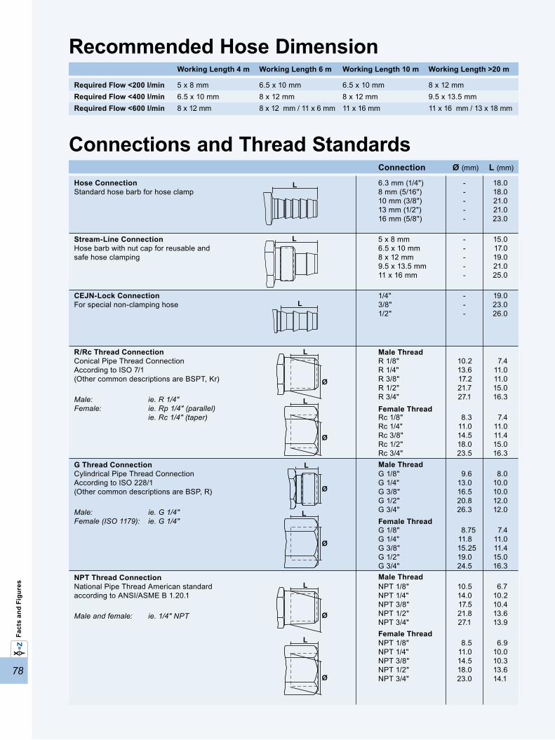
Connections and Thread StandardsConnection Ø (mm) L (mm)
Hose Connection Standard hose barb for hose clamp
Stream-Line Connection Hose barb with nut cap for reusable and safe hose clamping
CEJN-Lock Connection For special non-clamping hose
R/Rc Thread Connection Conical Pipe Thread Connection According to ISO 7/1 (Other common descriptions are bSPT, Kr)
Male: ie. R 1/4" Female: ie. Rp 1/4" (parallel) ie. Rc 1/4" (taper)
g Thread Connection Cylindrical Pipe Thread Connection According to ISO 228/1 (Other common descriptions are bSP, R)
Male: ie. G 1/4" Female (ISO 1179): ie. G 1/4"
NPT Thread Connection National Pipe Thread American standard according to ANSI/ASME b 1.20.1
Male and female: ie. 1/4" NPT
Recommended Hose dimensionRequired Flow <200 l/minRequired Flow <400 l/minRequired Flow <600 l/min
5 x 8 mm 6.5 x 10 mm 6.5 x 10 mm 8 x 12 mm6.5 x 10 mm 8 x 12 mm 8 x 12 mm 9.5 x 13.5 mm8 x 12 mm 8 x 12 mm / 11 x 6 mm 11 x 16 mm 11 x 16 mm / 13 x 18 mm
Working Length 4 m Working Length 6 m Working Length 10 m Working Length >20 m
Male Thread
Female Thread
Male Thread
Female Thread
Male Thread
Female Thread
• • • • • • • • • • • • • N/A 1/8" 1/4" 1/4" 1/4" 1/4" 1/4" 1/4" 3/8" 3/8" 3/8" 3/8" 1/2" 2.5 5.0 5.5 6.5 5.3 7.5 7.6 7.4 9.5 10.4 9.5 10.4 11.0 10 35 16 16 16 16 16 35 16 16 16 35 16 80 580 1050 1450 925 1950 2100 1950 3450 3900 2350 3950 3750 • • • • • • • • • • • • • • • • • • • • • • • • • • • • • • • • • • • • • • • • • • • • • • • • • • • • • • • • • • • • • • • • • • • • • • • • • • • • • • • • • • • • • • • • • • • • • • • • • • • • • • • • • • • • • • • • • • • • • • • • • • • • • • • • • • • • • • • • • • • • • • • • • • • • •
• • • • • • • • • • • • • • • • • • • • • • • • • • • • • • • • • • • • • • • • • • • • • • • • • • • • • • • • • • • • • • • • • • • • • • • • • • • • • • • • • • • • • • • • • • • • • • • • • • • • • • • • • • • • • • • • • • • • • • • • • • • • • • • • • • • • • • •
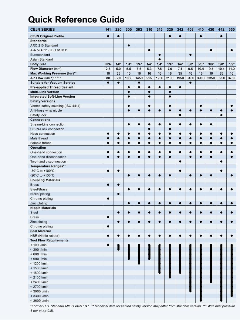
Quick Reference guideCEJN SERIES 141 220 300 303 310 315 320 342 408 410 430 442 550
CEJN Original ProfileStandards ARO 210 Standard A-A 59439* / ISO 6150 b Eurostandard Asian StandardBody SizeFlow diameter (mm)Max Working Pressure (bar)**Air Flow (l/min)** *** Suitable for Vacuum ServicePre-applied Thread SealantMulti-Link VersionIntegrated Soft-Line VersionSafety Versions Vented safety coupling (ISO 4414) Anti-hose whip nipple Safety lockConnections Stream-Line connection CEJN-Lock connection Hose connection Male thread Female threadOperation One-hand connection One-hand disconnection Two-hand disconnectionTemperature Ranges** -30°C to +100°C -20°C to +100°CCoupling Materials brass Steel/brassNickel plating Chrome platingZinc plating Nipple Materials Steel brass Zinc plating Chrome platingSeal Material NbR (Nitrile rubber)Tool Flow Requirements < 100 l/min < 300 l/min < 600 l/min < 900 l/min < 1200 l/min < 1500 l/min < 1800 l/min < 2100 l/min < 2400 l/min < 2700 l/min < 3000 l/min < 3300 l/min < 3600 l/min
*Former U.S. Standard MIL C 4109 1/4". **Technical data for vented safety version may differ from standard version. *** With inlet pressure 6 bar at ∆p 0.5).

»
The GlobalQuick Connect Specialist
www.cejn.com
With operations on five continents, CEJN provides high-performing, fluid-power
products to customers all over the world. For more information, visit www.cejn.com.
Pneumatics – Easy-to-handle couplings offering high efficiency and long life
gas – Non-interchangeable couplings with automatic locking and double seals
Breathing Air – Couplings that meet stringent safety certification requirements
Fluids – Couplings for fluid and vacuum applications, including a non-drip style
Hydraulics – Heavy-duty couplings for demanding medium-pressure applications
High-pressure Hydraulics – Quick couplings for extremely high-pressure applications
WEO Plug-In – Threadless hose fittings that simply “plug in” to ports
Multi & Auto – Couplings and nipples designed to be built into manifolds and plates