Embed Size (px)
Citation preview

Nickel Cadmium Clear Case Pocket Plate Battery
Installation and Operation ManualNickel Cadmium Clear Case Battery
Effective: December 2005
Alpha Technologies

PowerAlpha Technologies ®
Nickel Cadmium Clear Case
745-680-B6-001, Rev A
Effective Date: December 2005Copyright© 2005
Alpha Technologies, Inc.
Contacting Alpha Technologies: www.alpha.comor
For general product information and customer service (7 AM to 5 PM, Pacifi c Time), call
1-800-863-3930,
For complete technical support, call
1-800-863-33647 AM to 5 PM, Pacifi c Time or 24/7 emergency support
NOTE:Photographs contained in this manual are for illustrative purposes only. These photographs may not match your installation.
NOTE:Operator is cautioned to review the drawings and illustrations contained in this manual before proceeding. If there are questions regarding the safe operation of this product, please contact Alpha Technologies or your nearest Alpha representative.
NOTE:Alpha shall not be held liable for any damage or injury involving its enclosures, power supplies, generators, batteries, or other hardware if used or operated in any manner or subject to any condition not consistent with its intended purpose, or is installed or operated in an unapproved manner, or improperly maintained.
member of The GroupTM
745-680-B6-001 Rev. A4
Table of Contents
Safety Notes .......................................................................................................................... 6
1.0 Installation................................................................................................................... 8
2.0 Electrolyte ................................................................................................................... 92.1 Preparation ...................................................................................................... 92.2 Filling Cells ....................................................................................................... 92.3 Topping Up ..................................................................................................... 102.4 Renewal ......................................................................................................... 10
3.0 Charging ....................................................................................................................113.1 Pre-Charge Preparation ..................................................................................113.2 General Charge ..............................................................................................113.3 Equalizing Charge.......................................................................................... 123.4 Floating Charge ............................................................................................. 13
4.0 Maintenance ............................................................................................................. 134.1 Inspection Check Points ................................................................................ 13
5.0 Storage ..................................................................................................................... 14
6.0 Replacement Parts ................................................................................................... 14
7.0 Forms ........................................................................................................................ 15
8.0 Specifi cations............................................................................................................ 178.1 General Specifi cations ................................................................................... 178.2 Discharge Voltage .......................................................................................... 18
5745-680-B6-001 Rev. A
Tables and Figures
Table 3-1, Equalizing Charge Voltage ................................................................................. 12
Table 3-2, Floating Charge Voltage ..................................................................................... 13
Table 4-1, Inspection Check Points ..................................................................................... 13
Fig. 7-1, Charge Recording Form ........................................................................................ 15
Fig. 7-2, Discharge Recording Form ................................................................................... 16
Table 8-1, Dimensions and Weight ...................................................................................... 17
Table 8-2, Discharge End Voltage 1.14Vpc ......................................................................... 18
Table 8-3, Discharge End Voltage 1.10Vpc ......................................................................... 19
Table 8-4, Discharge End Voltage 1.06Vpc ......................................................................... 20
Table 8-5, Discharge End Voltage 1.0Vpc ........................................................................... 21
Table 8-6, Discharge End Voltage 0.9Vpc ........................................................................... 22
Table 8-7, Discharge End Voltage 0.7Vpc ........................................................................... 22

745-680-B6-001 Rev. A6
Safety NotesReview the drawings and illustrations contained in this manual before proceeding. If there are any questions regarding the safe installation or operation of the system, contact Alpha Technologies or the nearest Alpha representative. Save this document for future reference.To reduce the risk of injury or death, and to ensure the continued safe operation of this product, the following symbols have been placed throughout this manual. Where these symbols appear, use extra care and attention.
The use of ATTENTION is only for specifi c regulatory/code requirements that may affect the placement of equipment and installation procedures.
ATTENTION:
NOTE:A NOTE gives readers additional information to help them complete a specifi c task or procedure.
CAUTION!The use of CAUTION indicates safety information intended to PREVENT DAMAGE to material or equipment.
WARNING!
A WARNING presents safety information to PREVENT INJURY OR DEATH to the technician or user.
7745-680-B6-001 Rev. A
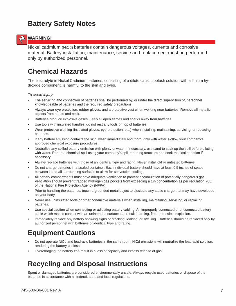
Chemical HazardsThe electrolyte in Nickel Cadmium batteries, consisting of a dilute caustic potash solution with a lithium hy-droxide component, is harmful to the skin and eyes.
To avoid injury:The servicing and connection of batteries shall be performed by, or under the direct supervision of, personnel knowledgeable of batteries and the required safety precautions.Always wear eye protection, rubber gloves, and a protective vest when working near batteries. Remove all metallic objects from hands and neck.Batteries produce explosive gases. Keep all open fl ames and sparks away from batteries.Use tools with insulated handles, do not rest any tools on top of batteries.Wear protective clothing (insulated gloves, eye protection, etc.) when installing, maintaining, servicing, or replacing batteries.If any battery emission contacts the skin, wash immediately and thoroughly with water. Follow your company’s approved chemical exposure procedures.Neutralize any spilled battery emission with plenty of water. If necessary, use sand to soak up the spill before diluting with water. Report a chemical spill using your company’s spill reporting structure and seek medical attention if necessary.Always replace batteries with those of an identical type and rating. Never install old or untested batteries.Do not charge batteries in a sealed container. Each individual battery should have at least 0.5 inches of space between it and all surrounding surfaces to allow for convection cooling.All battery compartments must have adequate ventilation to prevent accumulation of potentially dangerous gas. Ventilation should prevent trapped hydrogen gas pockets from exceeding a 1% concentration as per regulation 70E of the National Fire Protection Agency (NFPA).Prior to handling the batteries, touch a grounded metal object to dissipate any static charge that may have developed on your body.Never use uninsulated tools or other conductive materials when installing, maintaining, servicing, or replacing batteries. Use special caution when connecting or adjusting battery cabling. An improperly connected or unconnected battery cable which makes contact with an unintended surface can result in arcing, fi re, or possible explosion.Immediately replace any battery showing signs of cracking, leaking, or swelling. Batteries should be replaced only by authorized personnel with batteries of identical type and rating.
•
•
•••
•
•
••
•
•
•
•
•
Battery Safety Notes
Recycling and Disposal InstructionsSpent or damaged batteries are considered environmentally unsafe. Always recycle used batteries or dispose of the batteries in accordance with all federal, state and local regulations.
Equipment CautionsDo not operate NiCd and lead-acid batteries in the same room. NiCd emissions will neutralize the lead-acid solution, rendering the battery useless.Overcharging the battery can result in a loss of capacity and excess release of gas.
•
•
WARNING!
Nickel cadmium (NiCd) batteries contain dangerous voltages, currents and corrosive material. Battery installation, maintenance, service and replacement must be performed only by authorized personnel.
745-680-B6-001 Rev. A8
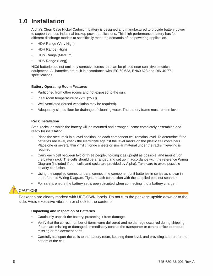
1.0 InstallationAlpha’s Clear Case Nickel Cadmium battery is designed and manufactured to provide battery power to support various industrial backup power applications. This high performance battery has four different discharge models to specifi cally meet the demands of the powering application.
HDV Range (Very High)HDH Range (High)HDM Range (Medium)HDS Range (Long)
NiCd batteries do not emit any corrosive fumes and can be placed near sensitive electrical equipment. All batteries are built in accordance with IEC 60 623, EN60 623 and DIN 40 771 specifi cations.
Battery Operating Room FeaturesPartitioned from other rooms and not exposed to the sun.Ideal room temperature of 77ºF (25ºC).Well ventilated (forced ventilation may be required).Adequately sloped fl oor for drainage of cleaning water. The battery frame must remain level.
Rack InstallationSteel racks, on which the battery will be mounted and arranged, come completely assembled and ready for installation.
Place the steel rack in a level position, so each component cell remains level. To determine if the batteries are level, check the electrolyte against the level marks on the plastic cell containers. Place one or several thin vinyl chloride sheets or similar material under the racks if leveling is required.Carry each cell between two or three people, holding it as upright as possible, and mount it on the battery rack. The cells should be arranged and set up in accordance with the reference Wiring Diagram (included if both cells and racks are provided by Alpha). Take care to avoid possible polarity confusion.Using the supplied connector bars, connect the component unit batteries in series as shown in the reference Wiring Diagram. Tighten each connection with the supplied pole nut spanner. For safety, ensure the battery set is open circuited when connecting it to a battery charger.
••••
••••
•
•
•
•
CAUTION!
Packages are clearly marked with UP/DOWN labels. Do not turn the package upside down or to the side. Avoid excessive vibration or shock to the contents.
Unpacking and Inspection of BatteriesCautiously unpack the battery, protecting it from damage. Verify that the correct number of items were delivered and no damage occurred during shipping. If parts are missing or damaged, immediately contact the transporter or central offi ce to procure missing or replacement parts. Carefully transport the cells to the battery room, keeping them level, and providing support for the bottom of the cell.
••
•
9745-680-B6-001 Rev. A
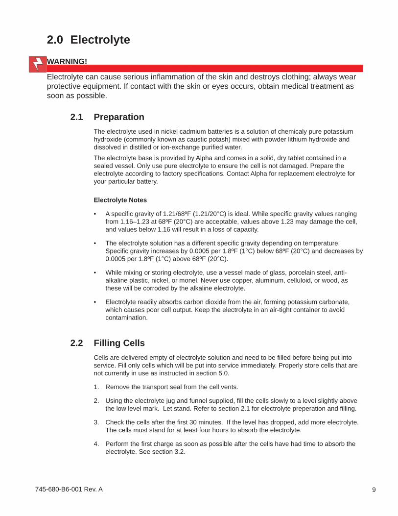
2.1 PreparationThe electrolyte used in nickel cadmium batteries is a solution of chemicaly pure potassium hydroxide (commonly known as caustic potash) mixed with powder lithium hydroxide and dissolved in distilled or ion-exchange purifi ed water. The electrolyte base is provided by Alpha and comes in a solid, dry tablet contained in a sealed vessel. Only use pure electrolyte to ensure the cell is not damaged. Prepare the electrolyte according to factory specifi cations. Contact Alpha for replacement electrolyte for your particular battery.
Electrolyte Notes
A specifi c gravity of 1.21/68ºF (1.21/20°C) is ideal. While specifi c gravity values ranging from 1.16–1.23 at 68ºF (20°C) are acceptable, values above 1.23 may damage the cell, and values below 1.16 will result in a loss of capacity.
The electrolyte solution has a different specifi c gravity depending on temperature. Specifi c gravity increases by 0.0005 per 1.8ºF (1°C) below 68ºF (20°C) and decreases by 0.0005 per 1.8ºF (1°C) above 68ºF (20°C).
While mixing or storing electrolyte, use a vessel made of glass, porcelain steel, anti-alkaline plastic, nickel, or monel. Never use copper, aluminum, celluloid, or wood, as these will be corroded by the alkaline electrolyte.
Electrolyte readily absorbs carbon dioxide from the air, forming potassium carbonate, which causes poor cell output. Keep the electrolyte in an air-tight container to avoid contamination.
2.2 Filling CellsCells are delivered empty of electrolyte solution and need to be fi lled before being put into service. Fill only cells which will be put into service immediately. Properly store cells that are not currently in use as instructed in section 5.0.
Remove the transport seal from the cell vents.
Using the electrolyte jug and funnel supplied, fi ll the cells slowly to a level slightly above the low level mark. Let stand. Refer to section 2.1 for electrolyte preperation and fi lling.
Check the cells after the fi rst 30 minutes. If the level has dropped, add more electrolyte. The cells must stand for at least four hours to absorb the electrolyte.
Perform the fi rst charge as soon as possible after the cells have had time to absorb the electrolyte. See section 3.2.
•
•
•
•
1.
2.
3.
4.
2.0 Electrolyte
WARNING!
Electrolyte can cause serious infl ammation of the skin and destroys clothing; always wear protective equipment. If contact with the skin or eyes occurs, obtain medical treatment as soon as possible.

745-680-B6-001 Rev. A10
2.0 Electrolyte, continued
2.3 Topping UpSince water electrolysis and evaporation are constantly taking place in the cell, causing the electrolyte level to lower over time, occasional topping up of the electrolyte is needed.
Check the electrolyte level visually from the outside of the cell.Keep the electrolyte between the minimum and maximum level marks. Only use distilled or ion-exchange purifi ed water to top off the electrolyte.
••
NOTE:Charging accelerates the loss of water from the cell. Be sure to top up the cell before a charge or recharge.
2.4 RenewalOver time, the density of electrolyte slowly decreases and it may accumulate various contaminates. Therefore, it is necessary to renew the electrolyte periodically. A renewal should generally be conducted once every fi ve to six years, during which time, the specifi c gravity will likely have fallen to the lowest limit. Renew the electrolyte in the cell when:
The specifi c gravity has fallen below 1.16/68ºF (1.16/20ºC).
The cells fail to work at the rated capacity.
Contaminates or foreign materials, such as potassium carbonate, in the electrolyte have accumulated beyond 100 grams per liter.
Renewal Steps
Discharge the battery to 0.6–0.8Vpc at a 5 hour rate current (C5).
After discharging, disconnect each cell from the string.
Open the fi ller cap of each cell, insert a siphon through the fi ller tube, and drain the old electrolyte completely. Dispose of the electrolyte in accordance with applicable local, state, and federal regulations. See section 2.1 Electrolyte Notes for more information.
Do not allow the cells to remain empty for too long or rinse the interior with water. Fill up each cell with new electrolyte, using a funnel and a jug (both supplied). Only use type HONDA B-20 or A electrolyte. Ensure the specifi c gravity of the solution is 1.21 ± 0.01.
Close the vent valves and clean the outside of each cell.
Make sure all cells are put in place and properly connected as they were before.
Conduct an equalizing charge according to section 3.3.
•
•
•
1.
2.
3.
4.
5.
6.
7.
11745-680-B6-001 Rev. A
About Charging TemperaturesAn electrolyte temperature of 68°F (20°C)–77°F (25°C) is ideal for charging. The temperature of the electrolyte gradually rises as charging continues. Cells are capable of withstanding an electrolyte temperature of up to113°F (45°C) without damage or loss of capacity.
3.2 General ChargeThe charging current should equal 10% of the battery capacity. For example, the HDS 20P has a capacity of 20AH and requires a charging current of 2 Amps for 20 hours.
Charge at 0.1 x C10(A) for 20 hours until the charging voltage has risen to a constant 1.65–1.80Vpc for 2.5–3 hours.
Check all the cells for the proper electrolyte density and level.
Discharge the battery at a 5 hour rate to 1.0Vpc level. (See section 7.1)
Charge at 0.1 x C10(A) for 20 hours until the charging voltage has risen to a constant 1.65–1.80Vpc for 2.5–3 hours.
Check all the cells for proper electrolyte density and level.
1.
2.
3.
4.
5.
NOTE:The charge state of the battery cannot be judged by measuring the specifi c gravity of its electrolyte.
3.0 Charging
CAUTION!
Cells can withstand temperatures up to 122°F (50°C) for short periods of time, but high temperatures should be avoided. If the temperature exceeds 113°F (45°C), suspend charging temporarily, and resume after the temperature has dropped suffi ciently.
NOTE:Refer to your particular charger’s manual for specifi c instructions regarding charger setup and operation.
3.1 Pre-Charge Preparation
Verify that the AC power source and the battery charger are in normal condition.
Measure the voltage of the entire battery as well as the voltage of each cell.
Check the specifi c gravity and temperature of the electrolyte for irregularities.
Connect the negative pole of the battery to the negative terminal of the charger and the positive pole to the the positive terminal.
Verify that the vent valve on each cell is closed.
1.
2.
3.
4.
5.

745-680-B6-001 Rev. A12
3.3 Equalizing ChargeAn equalizing charge restores battery capacity and effi ciency. Conduct an equalizing charge after initially fi lling the cell with electrolyte, renewing the electrolyte, when the cell voltages become unbalanced, or once every six months if the battery has been in fl oating charge mode, but not discharged.
Equalizing charge procedure after fi lling the cell with new electrolyte
Set the charging equipment to the “EQUALIZING” position.
After 24 hours, set the battery back to the fl oat charge by setting the charging equipment to the “FLOAT” position.
Equalizing charge procedure after discharge or voltage imbalance
Set the charging equipment to the “EQUALIZING” position.
After 8-10 hours, set the battery back to the fl oat charge by setting the charging equipment to the “FLOAT” position.
The proper voltage level (see Table 3-1) should be reached within a relatively short period. If this level, or higher, is not reached at the end of the equalizing charge, re-adjust the equalizing charge voltage or increase the charge time.
1.
2.
1.
2.
3.2 General Charge, continued
Cell voltage gradually rises as the charging continues. To maintain the charging current at the specifi ed rate, raise the rectifi er’s output voltage using the manual output voltage regulator.Taking measurements before and after charging and during discharge helps to track changes and identify problems. Use forms like those in section 7.0 to record the results. Wait two hours after charging before taking fi nal measurements, to allow the electrolyte to cool suffi ciently.
NOTE:After the fi rst charge, it is possible the battery may be discharged signifi cantly due to various tests involving load. If this occurs, charge again using the 10 hour rate current for 14 hours before putting the battery into service.
Cell Type Equalizing Charge Voltage (Vpc)HDV 1.52–1.57HDH 1.55–1.65HDM 1.55–1.65HDS 1.55–1.70
Table 3-1, Equalizing Charge Voltage

13745-680-B6-001 Rev. A
Table 3-2, Floating Charge Voltage
Cell Type Floating Charge Voltage (Vpc)HDV 1.40–1.42HDH 1.40–1.42HDM 1.40–1.45HDS 1.40–1.45
4.0 MaintenanceA battery gives optimum performance and longer life when given proper maintenance. It is important to inspect batteries periodically and record the results found at each inspection. Should something unusual be found, discover the cause as soon as possible.In order to determine the type and frequency of maintenance needed during normal service, conduct maintenance checks on the battery monthly during the fi rst few months of service.Practices for proper maintenance:
Clean the outside of the battery, especially the cell top and pole assemblies, at least once a month. Apply a suffi cient quantity of anti-rust oil (supplied by Alpha Technologies) or petroleum jelly to the nickel plated parts.
Tighten the poles or other connections occasionally.
Avoid using solder and similar materials to repair the battery.
Do not use sand paper or emery cloth on nickel plated parts as they will damage the nickel plating, resulting in increased resistance and rusting.
•
•
•
•
What to Check How Often Action RequiredFloating charge voltage Once a month Refer to section 3.4.Terminal voltage of cell Every 3 months Measure it with a voltmeter.Electrolyte level Every 2 months Refer to section 2.3.Clamped part of connector Every 3 months Using a pole spanner, tighten
bolts and nuts if loose.Appearance of container and cell cover
Every 3 months Check to see if any cell container or cell cover is broken.
Conduct equalizing charge Every 6 months Refer to section 3.3.Table 4-1, Inspection Check Points
3.0 Charging continued
3.4 Floating ChargeWhen connected to a fl oating charge, the battery is kept in a fully charged state. Floating charge voltage is normally 1.40–1.50Vpc (see Table 3-2) and the ampere is about 1/40 of a 5 hour rate current (1/200 C). Adjust these values accordingly; too much gassing or water consumption means the charging voltage is too high, whereas a gradual drop of capacity indicates the charging voltage is too low.Total fl oating charge voltage is obtained by multiplying the standard per-cell voltage by the number of cells within the battery. If something unusual is detected, check the load side for the cause.
4.1 Inspection Check Points
745-680-B6-001 Rev. A14
5.0 StorageA charged battery can be stored for up to six months but will suffer a gradual loss in capacity. If a battery is to be put back into service in less than six months, fully recharge it every three months with the 10 hour rate current for 14 hours.If a battery will be stored for a period longer than six months, completely discharge it, completely remove the electrolyte, thouroughly dry the inside, and close the vent plug of each cell.Store the battery in a room which is clean, cool, dark and dry. When putting the battery back into service, fi ll every cell with electrolyte as instructed in section 2.2 and then charge it fully by following the charging procedure explained in section 3.3.
6.0 Replacement PartsIf any accessory items or component parts are missing or damaged at the time of delivery or are found to be defective at the time of maintenance, replacements can be ordered by contacting customer service with the following information. Part numbers and nomenclatures can be found in the specifi cations.
Type of the battery and number of the cellsPart Number and NomenclatureQuantityReasons replacements ordered (e.g., lost or damaged during the transit or deteriorated while in use)Destination of the shipment, which should include the name and full address of the company and, if applicable, the name of the person responsible for receiving the shipment
••••
•
15745-680-B6-001 Rev. A
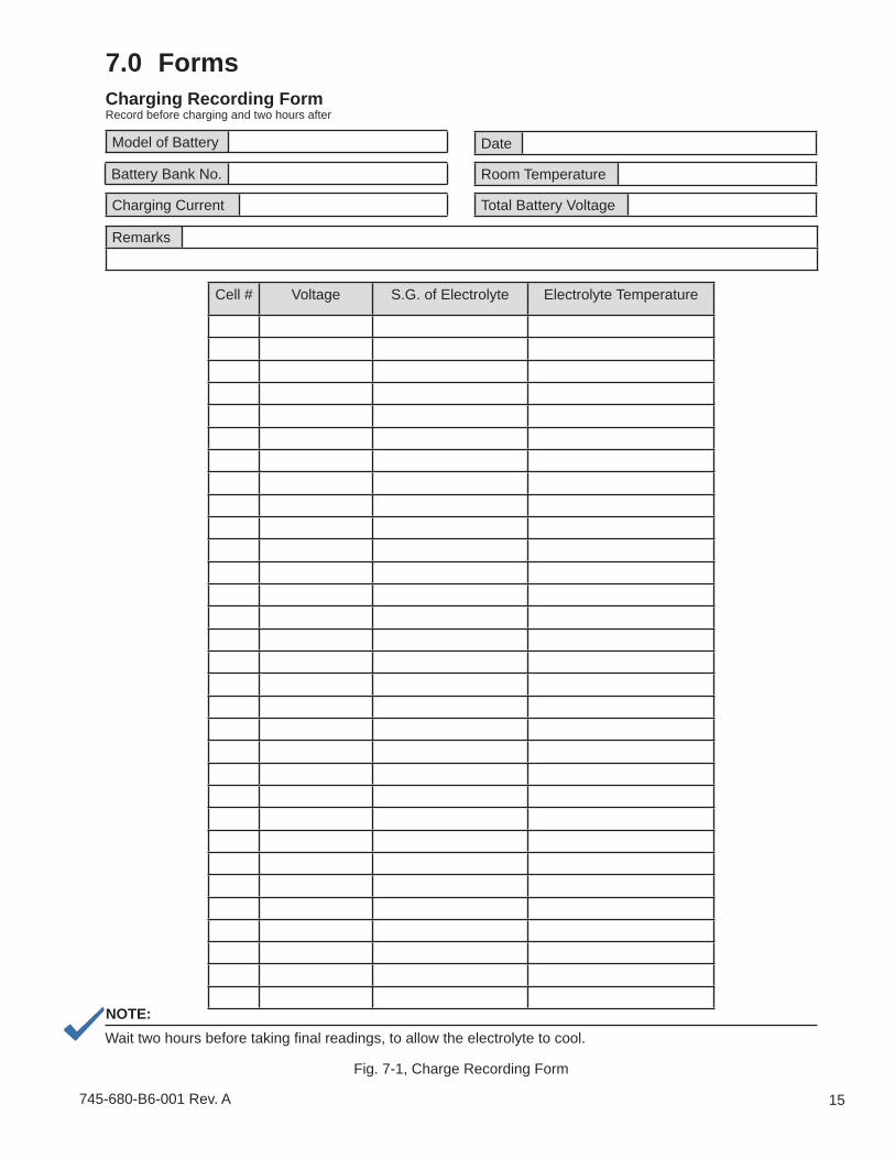
Cell # Voltage S.G. of Electrolyte Electrolyte Temperature
Model of Battery
Battery Bank No.
Total Battery Voltage
Room Temperature
Remarks
Date
Charging Current
NOTE:Wait two hours before taking fi nal readings, to allow the electrolyte to cool.
Fig. 7-1, Charge Recording Form
Charging Recording FormRecord before charging and two hours after
7.0 Forms
745-680-B6-001 Rev. A16
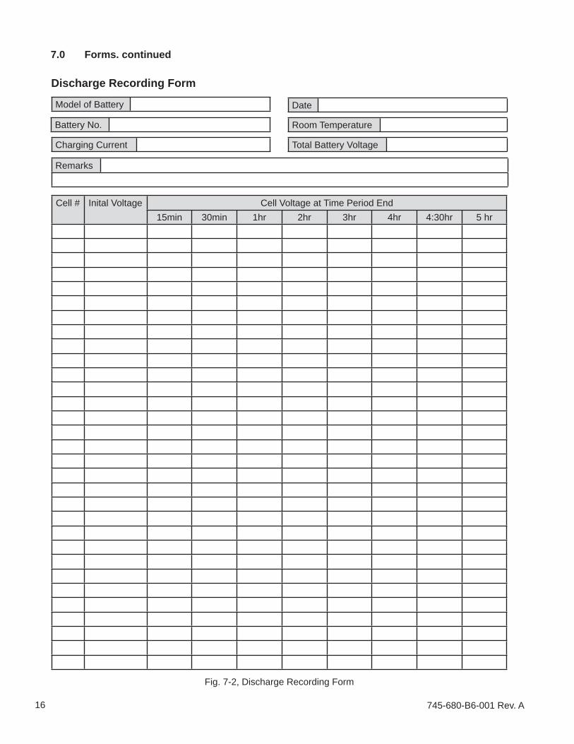
Fig. 7-2, Discharge Recording Form
Cell # Inital Voltage Cell Voltage at Time Period End15min 30min 1hr 2hr 3hr 4hr 4:30hr 5 hr
Model of Battery
Battery No.
Total Battery Voltage
Room Temperature
Remarks
Date
Charging Current
Discharge Recording Form
7.0 Forms. continued
17745-680-B6-001 Rev. A
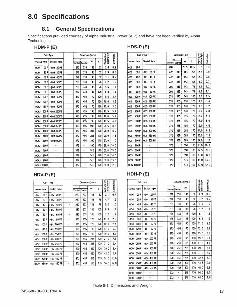
8.0 Specifi cations8.1 General Specifi cations
Table 8-1, Dimensions and Weight
HDM-P (E) HDS-P (E)
HDV-P (E) HDH-P (E)
Specifi cations provided courtesy of Alpha Industrial Power (AIP) and have not been verifi ed by Alpha Technologies.
745-680-B6-001 Rev. A18
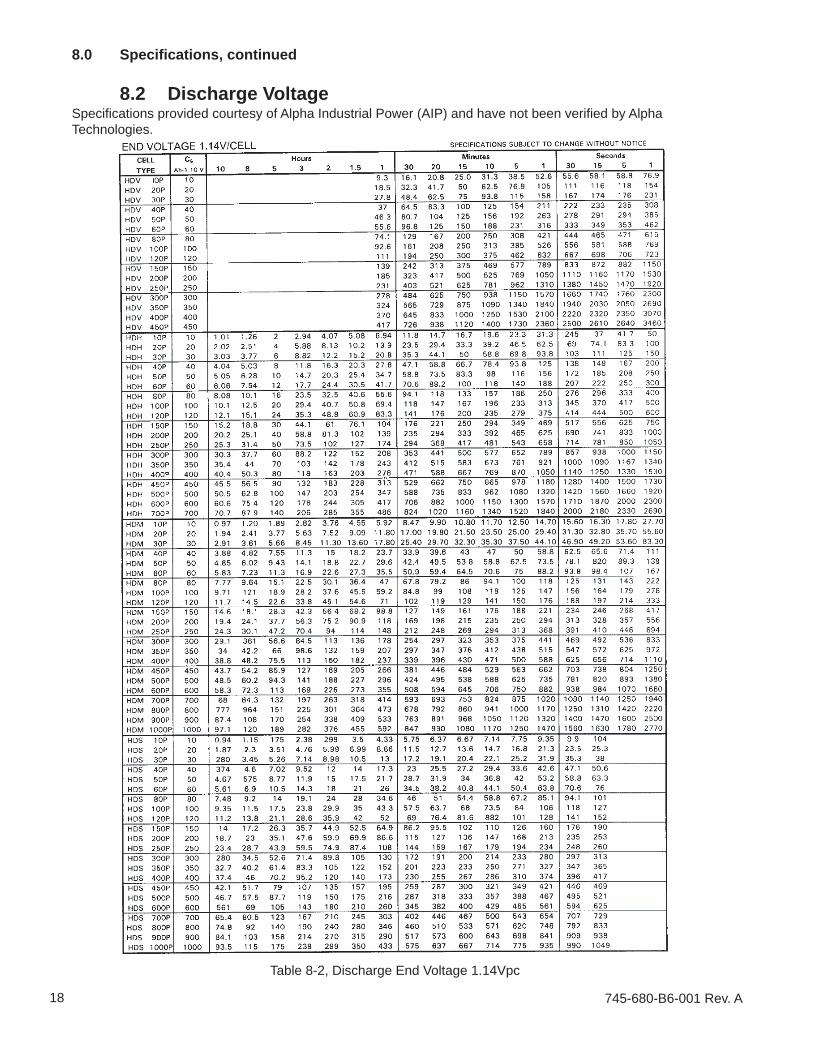
8.0 Specifi cations, continued
8.2 Discharge Voltage
Table 8-2, Discharge End Voltage 1.14Vpc
Specifi cations provided courtesy of Alpha Industrial Power (AIP) and have not been verifi ed by Alpha Technologies.
19745-680-B6-001 Rev. A
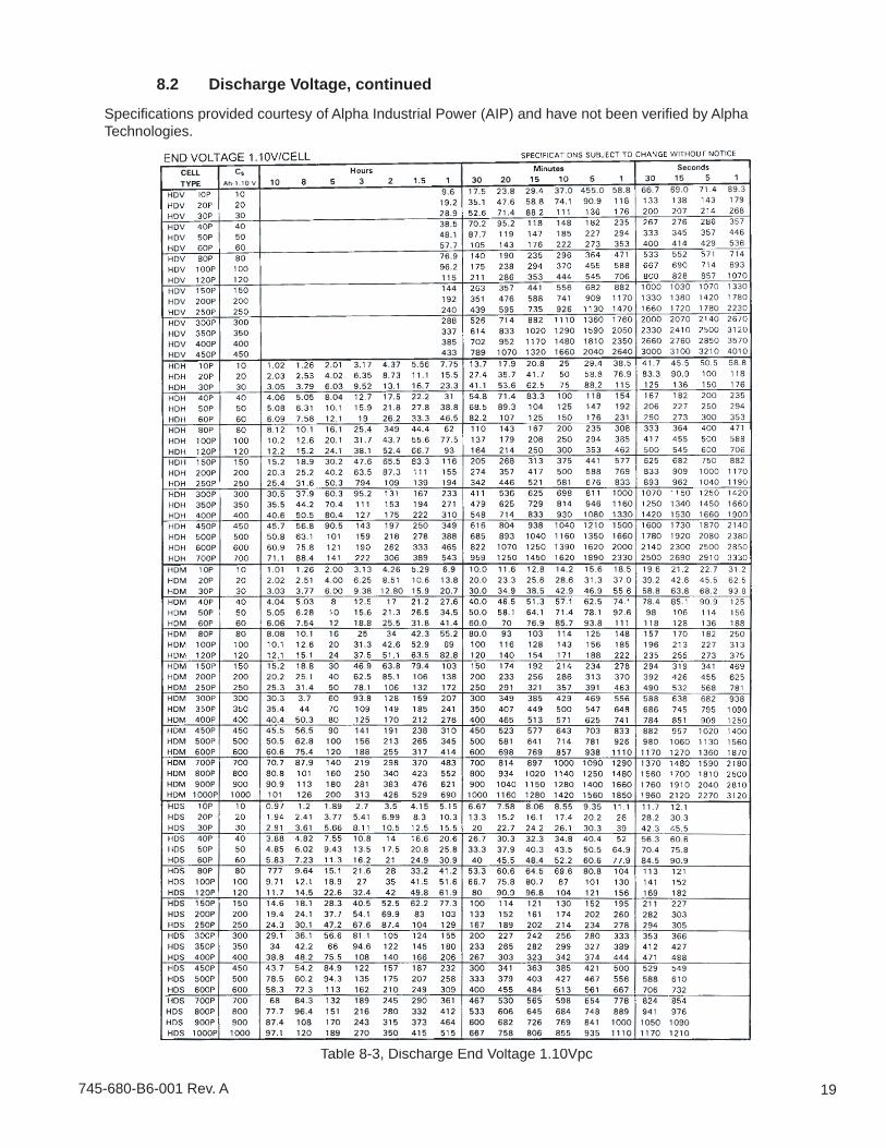
8.2 Discharge Voltage, continued
Table 8-3, Discharge End Voltage 1.10Vpc
Specifi cations provided courtesy of Alpha Industrial Power (AIP) and have not been verifi ed by Alpha Technologies.

745-680-B6-001 Rev. A20
8.2 Discharge Voltage, continued
Table 8-4, Discharge End Voltage 1.06Vpc
Specifi cations provided courtesy of Alpha Industrial Power (AIP) and have not been verifi ed by Alpha Technologies.
21745-680-B6-001 Rev. A
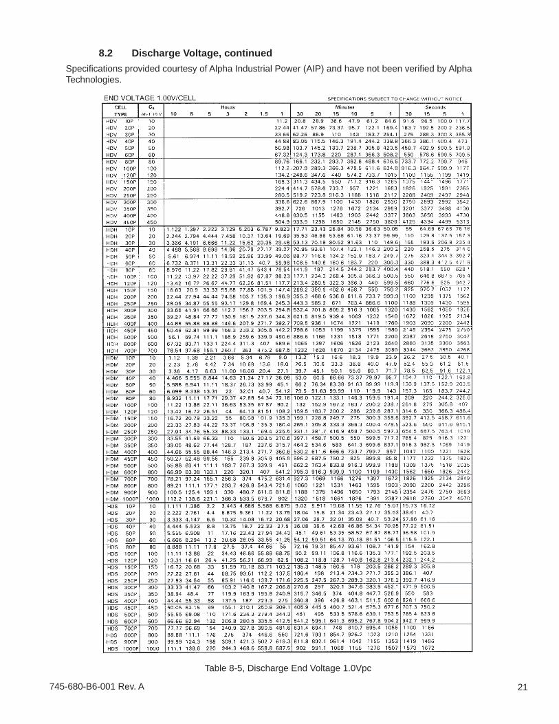
8.2 Discharge Voltage, continued
Table 8-5, Discharge End Voltage 1.0Vpc
Specifi cations provided courtesy of Alpha Industrial Power (AIP) and have not been verifi ed by Alpha Technologies.
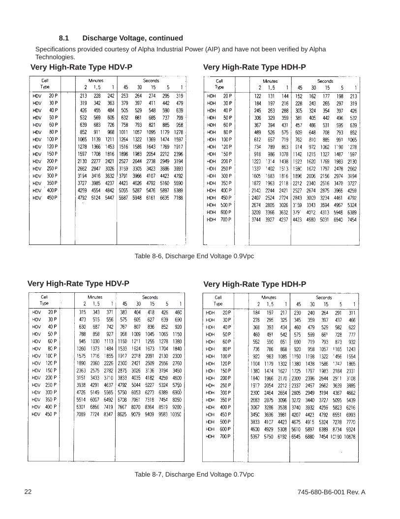
745-680-B6-001 Rev. A22
8.1 Discharge Voltage, continued
Table 8-6, Discharge End Voltage 0.9Vpc
Table 8-7, Discharge End Voltage 0.7Vpc
Very High-Rate Type HDV-P Very High-Rate Type HDH-P
Very High-Rate Type HDV-P Very High-Rate Type HDH-P
Specifi cations provided courtesy of Alpha Industrial Power (AIP) and have not been verifi ed by Alpha Technologies.
PowerAlpha Technologies ®
Due to continuing product improvements, Alpha reserves the right to change specifi cations without notice. Copyright © 2005 Alpha Technologies, Inc. All rights reserved. Alpha is a registered trademark of Alpha Technologies. 745-680-B6-001 Rev. A.
Alpha Technologies3767 Alpha WayBellingham, WA 98226USATel: +1(360) 647-2360Fax: +1(360) 671-4936Web: www.alpha.com
Alpha Technologies Ltd.4084 McConnell CourtBurnaby, BC, V5A 3N7CANADATel: +1(604) 430-1476Fax: +1(604) 430-8908
Alpha TechnologiesEurope Ltd.Twyford HouseThorleyBishop’s StortfordHertfordshireCM22 7PAUNITED KINGDOMTel: +44 (0) 1279-501110Fax: +44 (0) 1279-659870
Alpha Technologies, GmbHHansastrasse 8D-91126 SchwabachGERMANYTel: +49-9122-79889-0Fax: +49-9122-79889-21
Alphatec, LtdP.O. Box 56468Limassol, CyprusCYPRUSTel: +357-25-375675Fax: +357-25-359595
Alpha Technologies5 Avenue Victor HugoF-92140 Calmart FranceFRANCETel: +33-3-41-90-07-07Fax: +33-1-41-90-93-12