Embed Size (px)
Citation preview

PoE Lighting SystemEnergy Reporting StudyPart 1
February 2017
Prepared for:
Solid-State Lighting ProgramBuilding Technologies OfficeOffice of Energy Efficiency and Renewable EnergyU.S. Department of Energy
Prepared by:
Pacific Northwest National Laboratory

PoE Lighting System Energy Reporting Study
Part 1
Prepared for:
Solid-State Lighting Program
Building Technologies Office
Energy Efficiency and Renewable Energy
U.S. Department of Energy
Prepared by:
Pacific Northwest National Laboratory
February 2017
Authors:
Jason Tuenge
Michael Poplawski

Page ii
PNNL-26284

Page iii
Executive Summary
The replacement of today’s lighting infrastructure with LED products offers the potential for future
connected lighting systems (CLS) that could become a data-collection platform that enables greater
energy savings in buildings and cities. Such connected lighting systems can not only drastically
improve the energy performance of lighting and other building systems, but also enable a wide array
of services, benefits, and revenue streams that would enhance the value of lighting systems.
As LED technology matures, maximizing the energy savings from connected LED lighting systems
will become increasingly dependent on successful integration into the built environment. That’s why
the DOE Solid-State Lighting (SSL) Program is working closely with industry to identify and
collaboratively address the technology development needs of CLS. For several years now, a growing
number of wired and wireless network communication technologies have been integrated into
commercially available lighting devices. While most commercially available lighting devices
continue to require line-voltage AC power, a few new low-voltage DC technologies have also been
introduced into the market as options for powering LED devices. More recently, a technology that
has long supported non-lighting applications has become increasingly viable for LED lighting. This
approach, whereby a single Ethernet cable is used to both provide low-voltage DC power and enable
network communication, is generally referred to as Power over Ethernet (PoE).
Whereas wireless solutions offer reduced control system installation cost relative to traditional low-
voltage alternatives, PoE technology can offer additional cost savings by transmitting power and
communications over the same low-voltage cable, while also reducing demand for wireless
bandwidth. Although PoE technology was introduced at the start of this century, it was initially of
limited applicability to lighting systems due to power transmission limits for available Ethernet
cabling. However, PoE has become increasingly viable for lighting applications in recent years as
Ethernet cabling technology has evolved and relevant standards and specifications have adapted.
These gains have been compounded by ongoing improvements to the luminous efficacy of LED
technologies, increasing the number of LED luminaires suitable for use with Ethernet switches
capable of sourcing PoE. As a result, a growing number of manufacturers have introduced PoE
lighting systems in recent years.
Connected lighting systems that can report their own energy consumption can deliver increased
energy savings over conventional lighting solutions by facilitating data-driven energy management.
PoE technology has the potential to be key in bringing this capability to mainstream lighting
applications. This study is the first of a multi-part effort to explore the energy reporting capability of
commercially-marketed PoE connected lighting systems. It first provides a brief background on the
development of the various PoE technologies, ranging from standards-based to proprietary, and
illustrates the convergence of PoE power sourcing capabilities and LED luminaire power
requirements. It then classifies PoE system devices in relationship to how they are used in systems—
introducing new terminology as needed—and briefly describes different PoE system architectures
implemented by various lighting manufacturers. A discussion of existing standards and specifications
that address energy reporting is provided, and existing test setups and methods germane to
characterizing PoE system energy reporting performance are reviewed.

Page iv
Key Findings, Recommendations, and Path Forward
Most commercially-marketed PoE lighting systems provide some level of energy reporting. Little to
no detail, however, is typically provided regarding any aspect of where, when, and how energy is
reported. Some minimum level of detail describing where, when and how energy is reported should
be developed and adopted by manufacturers and technology providers. Industry might develop such
detail as a recommended practice, perhaps with assistance from DOE.
Energy loss in PoE cables and connections is not typically being accounted for explicitly in energy
reporting. Recommended practices should be developed to limit cable losses, especially for
installations where they are not explicitly reported. DOE is considering designing and executing a
study to characterize the impact of cable and connector losses on example PoE system architectures,
and to verify that any developed recommended practices achieve their stated goal.
At this time, DOE is not aware of any commercially-marketed PoE lighting devices or systems with
formal energy reporting performance claims. Some minimum level of detail describing how energy is
reported should be developed and adopted by manufacturers and technology providers. This detail
should include energy reporting performance, including accuracy and precision, as characterized per
industry standards and specifications. Standards or specifications describing test setups, test methods,
and performance classes suitable for characterizing the energy reporting performance claims of PoE
and other connected lighting devices and systems should be identified, or developed, as necessary, so
that competing claims (e.g., for different devices and systems, or from different manufacturers) can
be easily and fairly compared.
While a number of existing test methods for characterizing energy reporting performance are to some
extent suitable for PoE lighting devices and systems, none of them appear completely sufficient in
practice. Stakeholders who are experienced in the characterization of energy reporting performance
should contribute to and review any test setups and methods included in standards and specifications
being developed by appropriate organizations. Stakeholders who use or might use energy data should
contribute to and review any performance classes included in standards and specifications being
developed by appropriate organizations. DOE is currently engaged in this work.
Lighting industry stakeholders should encourage standard and specification development
organizations to coordinate existing and new activities, consolidate competing activities, minimize
overlap, and otherwise strive to efficiently develop and maintain test setups, methods, and
performance classes for characterizing energy reporting performance that are appropriate for PoE and
other lighting devices and systems.
Many physical (e.g., cabling, network architecture), logical (e.g., information/data models), and
temporal (e.g., network volume, traffic) differences among PoE lighting systems might need to be
addressed when characterizing energy reporting performance. DOE is not aware of any rigorous,
independent, publically-available studies characterizing the reporting accuracy and precision of
commercially-marketed PoE lighting devices and systems. DOE is considering whether or not to
design, execute, and publish one or more studies characterizing the reporting accuracy and precision
of multiple commercially-marketed PoE lighting devices and systems comprising one or more
possible PoE system architectures. DOE is also considering whether or not to utilize internally-
developed test setups and test methods for characterizing energy reporting performance claims, and
leverage lessons learned during the execution of these studies to modify or improve its test setups
and methods.
Page v
Acknowledgements
The authors are grateful to the following individuals for the input they provided to this study.
Chad Jones — Cisco Systems
Jason Potterf — Cisco Systems
Gary Trott — Cree
Dwight Stewart — Igor
Harry Aller — Innovative Lighting
Robert Hick — Leviton
John Seger — Leviton
Chris Gobok — Linear Technology
Heath Stewart — Linear Technology
Derek Cowburn — LumenCache
Don Barnetson — Lunera
Brian Lennan — MHT Lighting
Giovanni Frezza — Molex
Chris Isaacson — NuLEDs
Lisa Isaacson — NuLEDs
Rahul Shira — Philips Lighting
Lennart Yseboodt — Philips Lighting
Joe Deckard — Platformatics
Pete Johnson — Sifos
Gus Pohl — Silvertel
Michael Shulman — UL
The Energy Department is interested in feedback or comments on all aspects of this study. Please
write to [email protected] and include the study title in the subject line of your
email.

Page 6
Symbols and Abbreviations
A Ampere(s)
AC Alternating current
ANSI American National Standards Institute
API Application programming interface
ASTM American Society for Testing and Materials
ATIS Alliance for Telecommunications Industry Solutions
CMS Central management system
CoAP Constrained Application Protocol
DC Direct current
DCR DC resistance
EPS External power supply
Hz Hertz
ICEA Insulated Cable Engineers Association
IEC International Electrotechnical Commission
IEEE Institute of Electrical and Electronics Engineers
IETF Internet Engineering Task Force
IoT Internet of Things
IP Internet Protocol
ISO International Organization for Standardization
kWh Kilowatt-hour(s)
LAN Local area network
LLDP Link Layer Discovery Protocol
LNE Large network equipment
LPS Limited power source
MIB Management information base
MPS Maintain power signature
NEC National Electrical Code
NEMA National Electrical Manufacturers Association
NFPA National Fire Protection Association
NTP Network Time Protocol
Ω Ohm(s)
PD Powered device
POE, PoE Power over Ethernet
POE+ Power over Ethernet plus
POH Power over HDBaseT
PSE Power sourcing equipment
RFC Request for comments
SNE Small network equipment
SNMP Simple Network Management Protocol
TBD To be determined
TIA Telecommunications Industry Association
UL Underwriters Laboratories
UPOE Universal Power Over Ethernet
V Volt(s)
VLAN Virtual local area network
W Watt(s)

Page 7
Table of Contents
Executive Summary ................................................................................................................... iii
Symbols and Abbreviations ........................................................................................................ 6
1 Introduction ........................................................................................................................ 8
2 PoE Background ................................................................................................................ 9
3 PoE Connected Lighting Systems .....................................................................................13
3.1 LED Luminaire Input Power ...............................................................................14 3.2 System Architectures .........................................................................................15 3.3 System Manufacturers .......................................................................................17
4 PoE System Energy Reporting Characteristics ..................................................................20
4.1 IEEE and IETF ...................................................................................................23 4.2 Cisco EnergyWise ..............................................................................................24 4.3 IETF EMAN Working Group ...............................................................................25 4.4 IETF CoRE Working Group ................................................................................26
5 Characterizing PoE System Energy Reporting Accuracy ...................................................26
5.1 Measuring Electrical Energy ..............................................................................27 5.2 Measuring Electrical Power ................................................................................28 5.3 Measuring Cable Resistance .............................................................................30
6 Recommendations ............................................................................................................31
Appendix A — Lighting Manufacturer Literature Excerpts .........................................................37
References ...............................................................................................................................59

Page 8
1 Introduction
Advanced lighting control systems using dedicated low-voltage cables to transmit lighting control
signals (e.g., implementing DALI or DMX) were commercially available years before the
introduction of LED lighting systems for general lighting applications, but they have realized only
limited market penetration and energy savings in North America—largely due to their high real or
perceived cost, complexity, and various performance issues (e.g., occupant satisfaction). LED
technology has drastically reduced the cost barrier of high-performance dimming, and for the first
time enabled color tuning for myriad applications beyond theatrical lighting. Connected LED lighting
systems—comprised of intelligent LED luminaires with one or more network interfaces and one or
more sensors—can become platforms for the collection of data relevant to their surrounding
environment. Such data is the fuel that is powering emerging Internet of Things (IoT) capabilities
(e.g., space utilization, location services), and delivering it can add significant value to lighting
systems, potentially overcoming past cost and complexity barriers for the adoption of advanced
lighting controls.
The use of wireless communication technologies (e.g., via Bluetooth or Wi-Fi) to enable connected
LED lighting systems has become increasingly common in recent years. Although luminaires in
these systems typically receive line-voltage alternating-current (AC) power, there has been growing
interest in systems powered by low-voltage direct current (DC), such as those developed by members
of the EMerge Alliance, which can offer reduced AC-DC power conversion losses and installation
costs among other potential benefits. Power over Ethernet (PoE) technology offers the ability to
provide both low voltage DC power and communication over a standard Ethernet cable—also
referred to as a local area network (LAN) cable or Category cable.
PoE technology offers intriguing contrasts with wireless approaches for lighting systems. While
mobile devices inherently require wireless technologies, general lighting devices typically have fixed
locations where they are powered by line or low-voltage. The primary benefit of wireless technology
for lighting (and other building devices) is reduced installation costs—particularly in retrofits—
resulting from not having to run new wire to carry control signals and other data. PoE technology has
the benefit of carrying power and data over a single cable, and reducing demand for wireless
communication bandwidth. However, in existing buildings, this likely involves running new cable, as
very few existing lighting installations have Ethernet cable running to lighting devices. Further, the
power that can be delivered to an end-use device, such as a luminaire, by PoE technology has been
limited to levels below what most common lighting devices require. LED technology has reduced the
power required for lighting applications, and recent advances in PoE technology have yielded
substantial increases in the amount of power that can be delivered to a networked device over a
single cable. As a result, PoE technology is emerging in lighting and many other applications beyond
its historical foothold in telephony and networking equipment. A significant number of major LED
manufacturers have introduced PoE connected lighting systems in the past year, with more promising
to announce in the near future, making this a potentially disruptive technology.
PoE technology has long delivered and touted energy management as one of its primary capabilities.
Granular data on energy usage can be reported and used to manage installed systems so as to
minimize energy consumption and associated operating costs. Over time, historical data can become
a valuable resource for informing and justifying the subsequent installation of other identical or
similar systems. The accuracy of reported energy use is an important component of energy
management and other uses of energy data. Some but not all PoE systems provide some indication of

Page 9
their energy reporting accuracy. However, the applicability of and confidence in these values is not
always clear. For example, energy use data for a device (e.g., luminaire) reported by its power source
may have originated at the power source, or it may have been originally reported by the device, and it
may include or exclude cable losses. Furthermore, whereas some reported energy use data may be
derived from direct physical measurements, other data may be based on stored nominal values.
Existing standard test methods for characterizing the energy reporting accuracy of electric utility
meters used for generating customer bills are in many ways not applicable, or readily adaptable to
PoE devices or systems, or end-use devices (e.g., lighting) in general.
Connected lighting systems that can report their own energy consumption have the potential to
deliver significant energy savings by facilitating data-driven energy management. PoE technology
has the potential to be key in bringing this capability to mainstream lighting applications. This study
is the first of a multi-part effort to explore the energy reporting capability of commercially available
PoE connected lighting systems, aiming to benefit industry in the following ways:
increased transparency regarding accuracy and applicability of energy data reported by PoE
systems;
increased prevalence of energy reporting, whether via PoE or other means;
increased lighting industry awareness and understanding of the diversity/complexity and
benefits/limitations of PoE connected lighting systems and standards; and
improved IT industry understanding of lighting needs.
While this report does not include actual testing of PoE devices or systems, subsequent studies might,
for example, explore test and measurement setups and methods for accuracy characterization,
evaluate the impact of product selection on system energy consumption for a particular PoE system
component (e.g., Ethernet cables), and/or evaluate the energy reporting accuracy for complete PoE
lighting systems. Evaluations of real-world systems might compare the observed energy performance
against manufacture claims, as well as the observed energy performance variation across similar
devices and systems.
2 PoE Background
The Institute of Electrical and Electronics Engineers (IEEE) published “Ethernet” Standard 802.3 in
1985 to harmonize specifications for the physical and lower software layers for wired Ethernet,
thereby providing a backbone for local area networking (IEEE 1985).1 Ethernet has since continued
to evolve, delivering increasingly higher bandwidth speeds, a variety of physical media, and new
features like PoE. The first Ethernet switches—also called bridges—had one or more ports that each
provided two-way network communication with a device at the other end of an Ethernet cable (or
multiple Ethernet cables in series). Devices connected through Ethernet switches in this manner
created LANs. PoE switches introduced the ability to simultaneously source both power and two-way
network communication over the same Ethernet cable.2 A timeline of important PoE-related IEEE
standard publications is shown in Figure 2.1.
1 See http://standards.ieee.org/events/ethernet/history.html for details.
2 The term “Ethernet cable” is used herein in lieu of the terms “LAN cable” and “Category cable.”

Page 10
Figure 2.1 Timeline of PoE-related IEEE standards
The first meeting of an IEEE 802.3 study group exploring PoE was held in March 1999, and work
transitioned to the IEEE P802.3af task force in January 2000.3 Cisco Inline Power (ILP) was
launched in 2000, and Ethernet switches supporting this proprietary technology were capable of
sourcing 7.0 W per port (Cisco 2004). In June 2003 this capability was reflected in the requirements
for Class 2 power sourcing equipment (PSE) in IEEE 802.3af-2003, which also introduced a Class 3
PSE classification with a minimum capability of 15.4 W, as shown in Table 2.1 (IEEE 2003).
Notably, it essentially defined a PSE as an Ethernet switch port that sources power to a powered
device (PD). Although not defined or otherwise used in the document, the terms “POE” and “Power
over Ethernet” were included in its list of Keywords.4 802.3af was later incorporated in Clause 33 of
the 2005 and 2008 editions of IEEE 802.3.
The first meeting of the IEEE 802.3 “Power over Ethernet plus” study group was held in November
2004, and work transitioned to the IEEE P802.3at Power over Ethernet plus task force in September
2005. Cisco Enhanced POE was launched in 2008, and PoE switches supporting this proprietary
technology were capable of sourcing up to 20 W per port (Cisco 2008). In September 2009, IEEE
802.3at-2009 introduced a higher performing Class 4 PSE echelon with a minimum capability of
30.0 W (IEEE 2009). Although not defined or otherwise used in the document, the terms “POE+”
and “Power over Ethernet plus” were included in its list of Keywords. 802.3at was later incorporated
in Clause 33 of the 2012 and 2015 editions of IEEE 802.3 (IEEE 2015a).5
In addition to incorporating content from previous versions and intervening amendments, IEEE
802.3-2015 makes use of material published in other documents. For example, it references
American National Standards Institute (ANSI) standards developed by the Telecommunications
Industry Association (TIA) for Category 5 or better balanced twisted-pair telecommunications
3 The “P” prefix in “P802.3af” indicates the document is a draft standard in progress. Websites for IEEE 802.3-
series study groups and task forces can be found at http://www.ieee802.org/3/. 4 To avoid confusion, this report uses the term “802.3af” (rather than “POE” or “PoE”) when specifically referring
to IEEE 802.3af-2003, and uses the mixed-case “PoE” abbreviation more broadly. 5 An overview of recent revisions is provided at http://www.ieee802.org/3/status/index.html.
Page 11
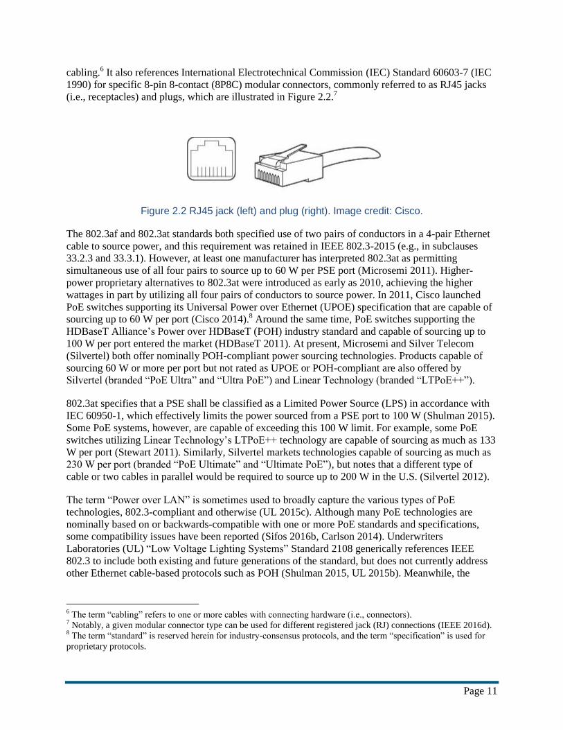
cabling.6 It also references International Electrotechnical Commission (IEC) Standard 60603-7 (IEC
1990) for specific 8-pin 8-contact (8P8C) modular connectors, commonly referred to as RJ45 jacks
(i.e., receptacles) and plugs, which are illustrated in Figure 2.2.7
Figure 2.2 RJ45 jack (left) and plug (right). Image credit: Cisco.
The 802.3af and 802.3at standards both specified use of two pairs of conductors in a 4-pair Ethernet
cable to source power, and this requirement was retained in IEEE 802.3-2015 (e.g., in subclauses
33.2.3 and 33.3.1). However, at least one manufacturer has interpreted 802.3at as permitting
simultaneous use of all four pairs to source up to 60 W per PSE port (Microsemi 2011). Higher-
power proprietary alternatives to 802.3at were introduced as early as 2010, achieving the higher
wattages in part by utilizing all four pairs of conductors to source power. In 2011, Cisco launched
PoE switches supporting its Universal Power over Ethernet (UPOE) specification that are capable of
sourcing up to 60 W per port (Cisco 2014).8 Around the same time, PoE switches supporting the
HDBaseT Alliance’s Power over HDBaseT (POH) industry standard and capable of sourcing up to
100 W per port entered the market (HDBaseT 2011). At present, Microsemi and Silver Telecom
(Silvertel) both offer nominally POH-compliant power sourcing technologies. Products capable of
sourcing 60 W or more per port but not rated as UPOE or POH-compliant are also offered by
Silvertel (branded “PoE Ultra” and “Ultra PoE”) and Linear Technology (branded “LTPoE++”).
802.3at specifies that a PSE shall be classified as a Limited Power Source (LPS) in accordance with
IEC 60950-1, which effectively limits the power sourced from a PSE port to 100 W (Shulman 2015).
Some PoE systems, however, are capable of exceeding this 100 W limit. For example, some PoE
switches utilizing Linear Technology’s LTPoE++ technology are capable of sourcing as much as 133
W per port (Stewart 2011). Similarly, Silvertel markets technologies capable of sourcing as much as
230 W per port (branded “PoE Ultimate” and “Ultimate PoE”), but notes that a different type of
cable or two cables in parallel would be required to source up to 200 W in the U.S. (Silvertel 2012).
The term “Power over LAN” is sometimes used to broadly capture the various types of PoE
technologies, 802.3-compliant and otherwise (UL 2015c). Although many PoE technologies are
nominally based on or backwards-compatible with one or more PoE standards and specifications,
some compatibility issues have been reported (Sifos 2016b, Carlson 2014). Underwriters
Laboratories (UL) “Low Voltage Lighting Systems” Standard 2108 generically references IEEE
802.3 to include both existing and future generations of the standard, but does not currently address
other Ethernet cable-based protocols such as POH (Shulman 2015, UL 2015b). Meanwhile, the
6 The term “cabling” refers to one or more cables with connecting hardware (i.e., connectors).
7 Notably, a given modular connector type can be used for different registered jack (RJ) connections (IEEE 2016d).
8 The term “standard” is reserved herein for industry-consensus protocols, and the term “specification” is used for
proprietary protocols.

Page 12
HDBaseT 5Play (HDBT5) working group was given approval in late 2014 to begin work on IEEE
1911, which will include POH (IEEE 2015c).
The first meeting of the IEEE 4-Pair Power over Ethernet (4PPoE) study group was held in March
2013, and work transitioned to the IEEE P802.3bt task force in December 2013. The scope of the
project includes augmenting the capabilities of 802.3at with 4-pair power and associated power
management information, while maintaining backwards-compatibility (Law 2016b). Goals include
support for increased power levels, enhanced power management, reduced cost, and improved
efficiency (IEEE 2016a). The new standard is expected to support a minimum of 49 W at the PD,
while continuing to comply with the 100 W limit for LPS (IEEE 2013a); intermediate limits are to be
determined. Final ratification is targeted for early 2018 (Law 2016a), and a number of manufacturers
have already introduced products marketed as complying with P802.3bt.
Table 2.1 IEEE 802.3-series standards overview
IEEE Standard 802.3-2015 Clause 33*
(incorporates 802.3at-2009)
P802.3bt
(in progress)
Category Type 1 Type 2 Type 3 Type 4
Number of conductor pairs
carrying power for highest
Class in Type
2 2 4 4
Channel maximum pair loop
DC resistance †
20.0 Ω 12.5 Ω TBD
≤ Type 2
TBD
≤ Type 3
Maximum pair DC current ‡ 0.350 A 0.600 A TBD
≥ Type 2
TBD
≥ Type 3
PSE port DC voltage 44.0 to 57.0 V 50.0 to 57.0 V TBD
≥ Type 2
TBD
≥ Type 3
Minimum PSE port power
capability for highest Class in
Type §
15.4 W
(Class 0 or 3)
30.0 W
(Class 4)
Type 2
< TBD <
Type 4
Type 3
< TBD <
100 W
PD port DC voltage 37.0 to 57.0 V 42.5 to 57.0 V TBD
≥ Type 2
TBD
≥ Type 3
Maximum PD port power for
highest Class in Type §
13.0 W
(Class 0 or 3)
25.5 W
(Class 4)
Type 2
< TBD <
Type 4
Type 3
< TBD <
100 W * Type 1 (Classes 0-3) requirements were introduced in 802.3af and retained in 802.3at, which introduced Type 2
(Class 4) requirements. † Whereas “loop” refers to two conductors effectively wired in series (from PSE to PD and back to PSE), “pair
loop” refers to two such loops wired in parallel (IEEE 2016c). ‡ Refers to the current sourced on one twisted pair of conductors; a second twisted pair is required to return
current in the opposite direction (UL 2015a). § Refers to top of capability range for highest Class in Type. Can operate at lower values.
IEEE 802.3-2015 provides definitions for a number of terms in Clause 1. The term “channel” only
referred to a band of transmitted frequencies, but this definition was amended in IEEE 802.3by-2016
to also refer to the data signal path.9 This aligned with usage in Clauses 40 and 55, which are
9 See http://www.ieee802.org/3/status/index.html for an overview of recent and forthcoming 802.3 amendments.

Page 13
referenced in Clause 33 and state that the “link segment” between Ethernet switch and device is
comprised of four duplex channels.
In contrast, the term “channel” as used when describing resistance requirements in Table 33-1 of
IEEE 802.3-2015 corresponds to the term “link section,” which refers to the electrical path on which
power is transferred from PSE to PD (IEEE 2016b). This usage appears to differ from usage in
subclause 33.4.9, which states that per ANSI/TIA-568-C.0 and ISO/IEC 11801 the “channel” cannot
exceed 100 meters in length. This language is similar to language in sections 25.4.9.2 and 40.7.2,
where the 100-meter limit is instead applied to the term “link segment,” which in Clause 33 refers to
the connection between the interfaces at each end of the electrical transmission medium (i.e., cabling)
between an “Endpoint” PSE and PD.
Subclause 33.1.3 of IEEE 802.3-2015 establishes that a PSE located at the end of a link segment is an
Endpoint PSE; it also permits an alternative approach, whereby a “Midspan” PSE is inserted as a
connector along the link segment between a non-PoE Ethernet switch and a PD. Although the link
segment and link section are equivalent for a PD sinking power from an Endpoint PSE, these terms
are not equivalent for a PD sinking power from a Midspan PSE, as shown in Figure 2.3.
Figure 2.3 Link segment and link section in different PoE and non-PoE configurations
3 PoE Connected Lighting Systems
PoE technology was initially developed to power low-wattage communication devices such as
Internet Protocol (IP) phones and wireless access points; most luminaires exceeded the early PoE
power limits. However, two concurrent and complementary processes have led to the increasing
viability of PoE in general lighting applications. First, each new generation of PoE standards and
technologies has accommodated loads of increasingly higher power. Second, luminous efficacy
Page 14
(lumens output per watt input) has been improving with each new generation of LED lighting
devices. The net effect is that a growing number of LED luminaires already or will soon have input
power requirements within commercially available PoE limits. Notably, the 2016 Progress Report of
the Illuminating Engineering Society (IES) was the first edition to use the term “Power over
Ethernet” (IES 2017).
3.1 LED Luminaire Input Power
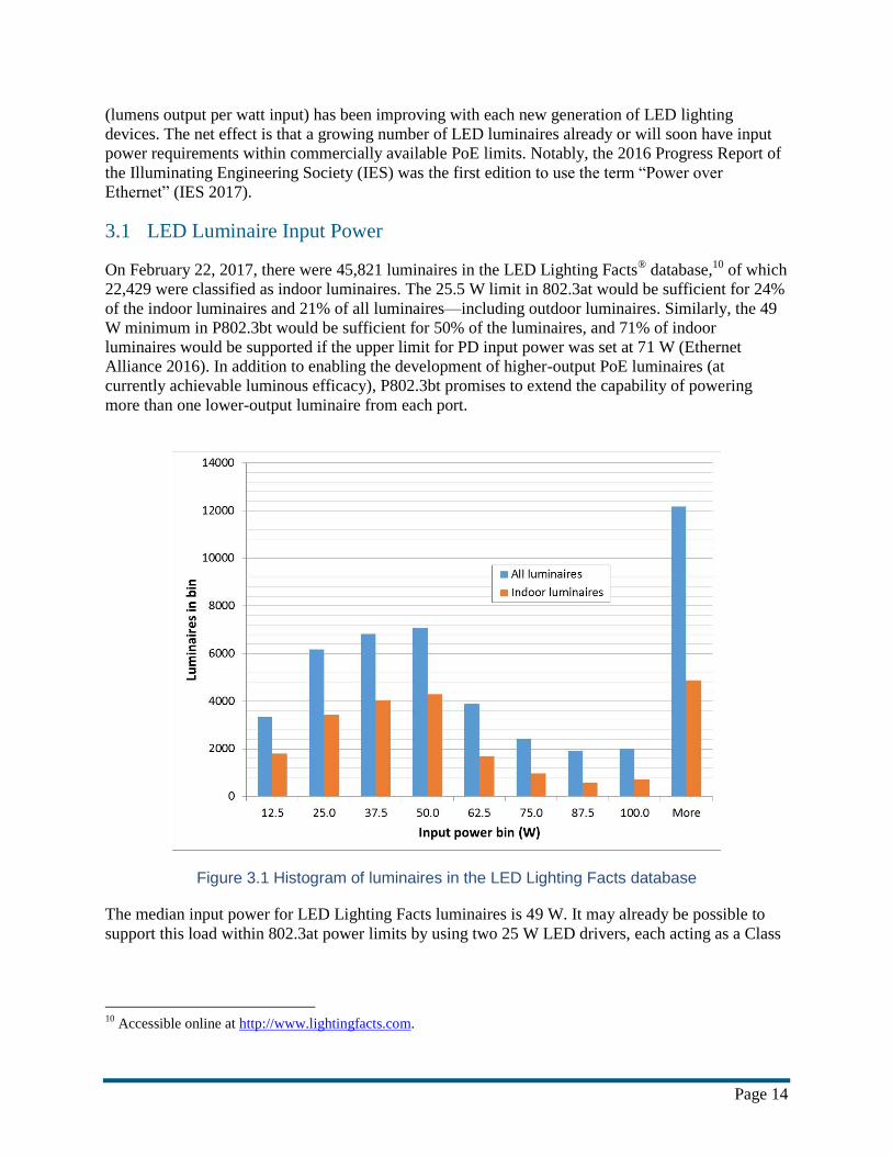
On February 22, 2017, there were 45,821 luminaires in the LED Lighting Facts® database,10 of which
22,429 were classified as indoor luminaires. The 25.5 W limit in 802.3at would be sufficient for 24%
of the indoor luminaires and 21% of all luminaires—including outdoor luminaires. Similarly, the 49
W minimum in P802.3bt would be sufficient for 50% of the luminaires, and 71% of indoor
luminaires would be supported if the upper limit for PD input power was set at 71 W (Ethernet
Alliance 2016). In addition to enabling the development of higher-output PoE luminaires (at
currently achievable luminous efficacy), P802.3bt promises to extend the capability of powering
more than one lower-output luminaire from each port.
Figure 3.1 Histogram of luminaires in the LED Lighting Facts database
The median input power for LED Lighting Facts luminaires is 49 W. It may already be possible to
support this load within 802.3at power limits by using two 25 W LED drivers, each acting as a Class
10
Accessible online at http://www.lightingfacts.com.
Page 15
4 PD.11 Although this would enable completely independent control of, in this example, two separate
LED modules (e.g., one for uplight, one for downlight in a direct-indirect application) within the
luminaire, any resultant benefits would be offset by increased cost and complexity, as each driver
requires its own Ethernet cable and dedicated PSE port.
3.2 System Architectures
While most installed PoE systems are comprised of PSEs and PDs that operate within IEEE 802.3at
limits, some—most notably those already using 4-pair power via Cisco UPOE devices—are not.
Components that operate outside IEEE 802.3at limits may not strictly fit IEEE definitions for PSE or
PD. As a result, the variety of viable PoE system architectures that might be installed today goes
beyond those comprised of networks connecting PSEs to PDs. To facilitate system architecture
comparisons, while avoiding confusion with IEEE terminology, the following terms are used herein:
PoE system—a system in which end-use devices (e.g., luminaires) receive all normal input
power via Ethernet cabling from a PoE switch, functioning either as direct PoE loads or as
indirect PoE loads; emergency power may be provided separately via energy storage device.
PoE controller—equipment that must be directly connected to one or more networked PoE
switches for communication via Ethernet cabling for proper PoE system operation (e.g., to
enable energy reporting); often referred to as a gateway, and in some cases serving or capable
of serving as one (i.e., providing an interface between systems using different communication
protocols).
PoE switch—equipment capable of providing power and two-way communication to IEEE
802.3-compliant PDs via Ethernet cabling; some PoE switches extend IEEE functionality
(e.g., Cisco UPOE-compliant switches support higher power devices but remain backwards-
compatible).
Direct PoE load—a device that receives power and two-way communication from a PoE
switch directly over Ethernet cabling, possibly with intermediate patch panel connections;
lighting system examples can include sensors, luminaires, and LED drivers; some direct PoE
loads can provide power and two-way communication to one or more indirect PoE loads via
Ethernet cables or other means.
Indirect PoE load—a device that receives power from a PoE switch indirectly via a direct
PoE load; lighting system examples can include sensors and luminaires.
Sensor—a device that generates data based on some measurement or detection from its
surrounding environment; examples include photosensors (which measure or detect changes
in light level), motion sensors (which detect new motion in a given field of view), wall-box
dimmers (which measure or detect human input intended to initiate a change in light level),
and smartphones (which contain myriad environmental sensors, and whose location generally
is linked to its owner).
Subclause 33.3.7 of IEEE 802.3-2015 states that when a local power source is provided, the PD may
draw some, none, or all its power from the power interface (i.e., the port used to source power from
the PSE). For the purposes of this report, it is assumed that all normal power for direct PoE loads will
be sourced from the PoE switch; emergency power may be delivered by other means (e.g., via
internal battery).
11
Section 725.121(B) of the 2017 National Electrical Code (NEC) addresses paralleled or otherwise interconnected
output connections from NEC Class 2 power sources (as distinct from IEEE Class 2 PSEs).

Page 16
An example of a possible PoE lighting system architecture is shown in Figure 3.2 to illustrate the
application of these terms and to facilitate discussion of commercially marketed PoE connected
lighting systems. Many variations in architecture are possible:
Inclusion of a PoE controller might be required.
Energy management functions might be performed by the PoE controller and/or by a central
management system (CMS) that also provides, for example, building or asset management
functions.
Energy management functions and data might be accessed indirectly, via the cloud, or via
direct connection to a virtual LAN (VLAN) comprising the networked PoE switches and
other PoE lighting system devices.
Personal control of luminaires might be provided via smartphone apps and other personal
devices (which might also function as sensors); in such scenarios control permissions are
generally limited, and for security reasons access is typically only via the VLAN.
One or more indirect PoE loads may sink power from a direct PoE load to maximize PoE
switch loading, which typically maximizes PSE efficiency. The use of indirect PoE loads also
limits the number of PoE switch ports required to implement a given PoE system. Notably,
non-Ethernet cabling is sometimes used to provide power from direct PoE loads to indirect
PoE loads with the intention of preventing direct connection of indirect PoE loads to PoE
switches; systems that use Ethernet cabling to source power for indirect PoE loads may be
designed for compatibility with 802.3 to ensure that improper installation does not damage
equipment or create safety issues.
Indirect PoE loads may be connected to direct PoE loads in series, or in parallel, depending
on the technology utilized.

Page 17
Figure 3.2 Example PoE lighting system. Dashed blue lines indicate Ethernet cabling not used to source power. Solid blue lines indicate Ethernet cabling used to source power. Black lines indicate non-Ethernet low voltage cabling used to source power.
3.3 System Manufacturers
A number of PoE lighting systems—herein limited to those in which luminaires receive all normal
input power directly or indirectly from a PoE switch—introduced prior to publication of this report
are summarized in Table 3.1 and discussed in the paragraphs that follow, in rough chronological
order of market introduction. Relevant excerpts from manufacturer literature, press releases, and
magazine articles are compiled in Appendix A for reference.

Page 18
Table 3.1 Summary of PoE lighting systems
Manufacturer
Cre
e
Igo
r
Inn
ov
ativ
e L
ighti
ng
Lu
men
Cac
he
MH
T L
igh
tin
g
Mo
lex
Nu
LE
DS
Ph
ilip
s
Pla
tfo
rmat
ics
Red
wo
od
/Com
mS
cope
Energy management
access
Direct via VLAN
Indirect via router
PoE controller Required
Optional
PoE switch 802.3af
802.3at
UPOE
Other
Direct PoE loads LED drivers
Luminaires
Sensors
Luminaires w/ sensors
Cabling to indirect
PoE loads
Ethernet
Non-Ethernet
Redwood Systems introduced a connected lighting system in 2010 featuring a line-voltage AC
“engine” that communicated with an Ethernet switch via Ethernet cable, similar to a 802.3 Midspan
PSE (LEDs Magazine 2010),12 and the ability to report on energy consumption. However, this 1st
generation engine did not provide power and two-way communication to a direct PoE load via
Ethernet cabling; instead, constant-current regulated power was sourced from the engine via two-
conductor cables that also facilitated communication between the engine and its lighting loads
(Redwood Systems 2010). The 2nd generation engine could be configured to source power and
communication over Ethernet cabling by way of a Redwood multi-cable “patch cord” between the
engine and a Redwood “patch panel” (Redwood Systems 2012). In 2013 CommScope acquired
Redwood Systems and launched the 3rd generation engine, featuring RJ45 ports that obviated the
patch cords but still required an intermediate patch panel for the engine to serve as a PoE switch
(Redwood Systems 2013). In 3rd generation systems, the engine powered either “gateways” or
“adapters” as direct PoE loads. The adapters, which were intended to enable LED luminaires to be
powered by and communicate with engines, combined a gateway with a sensor cluster that reported
on a variety of environmental parameters (e.g., light level, temperature, occupancy, and energy
consumption). Indirect PoE loads (luminaires or sensor clusters) sinked power from direct PoE loads
via Ethernet or non-Ethernet cabling. A “director” served as the PoE controller. CommScope
discontinued the Redwood product line in early 2016.13
12 Note that “LED light engine” is defined and used differently in IES RP-16-10 and IES LM-84-14, respectively.
13 From email correspondence dated January 4, 2017.

Page 19
Having previously developed luminaires for the Redwood Systems platform (Warren 2011), Lunera
developed its “PowerHive” system in 2012.14 The PowerHive “Power Distribution Control Unit”
provided power (normal and battery) and dimming control (either 0-10 V or Lutron EcoSystem) to
luminaires via Ethernet cabling (Lunera 2013). However, the system was later withdrawn from the
market by Lunera.
LumenCache introduced a hardware platform for PoE and other low-voltage systems in 2012
(Jacobson 2012). The platform is not specifically described as PoE but can provide power and
communication to luminaires and sensors over Ethernet cabling. The LumenCache “power
distribution module” can serve as a PoE switch once it is populated with “card modules” by one or
more partner developers. Alternatively, these card modules can be non-PoE LED drivers or source
power via Universal Serial Bus (USB). Per email correspondence with the manufacturer, the “power
management module” monitors the power distribution modules, and gateway software can calculate
energy usage for each device.
NuLEDs introduced a PoE lighting system in 2012 (CE Pro 2012) that only works with 802.3af,
802.3at, or UPOE switches. Direct PoE loads can include a standalone “SPICEbox” LED driver or a
luminaire with an integral SPICEbox. Multiple luminaires can be connected to a SPICEbox in
parallel via non-Ethernet cabling as indirect PoE loads; similarly, multiple sensors can be connected
to a SPICEbox in series via Ethernet cabling as indirect PoE loads. Energy reporting granularity
extends to the level of luminaires and sensors, and appears to originate at the SPICEbox.
Philips Lighting introduced a PoE lighting system in 2014 (Dewan 2014). The PoE switch must
comply with 802.3at, and luminaires can only be integrated into the system as direct PoE loads;
luminaire-integrated sensors are optional. The “EnvisionGateway” must be connected to the network
as a PoE controller. Luminaires report energy use to the EnvisionGateway via the PoE switch. The
EnvisionGateway does not receive or provide power via Ethernet cabling, but it can be used to
connect non-PoE lighting systems to the network for communication via Ethernet cabling.
Igor introduced a platform for PoE lighting systems in 2014 (Briggs 2014). The PoE switch must
comply with 802.3at or the UPOE specification, and Igor “Network Nodes” are direct PoE loads.
Indirect PoE loads can be luminaires, sensors, or Igor “Device Nodes.” Device Nodes can be
connected in series to a Network Node using Ethernet cabling, and can in turn source power to and
communicate with luminaires and sensors. Energy reporting granularity appears to extend to each
luminaire, and appears to originate at the direct PoE loads.
Innovative Lighting introduced a PoE lighting system in 2014 (Briggs 2014), and announced updates
in early 2017 (Strong 2017). The PoE switch must comply with 802.3at or the UPOE specification,
and direct PoE loads are “IntelliDrive” LED drivers. Luminaires and sensors (indirect PoE loads) are
connected to the IntelliDrive in parallel using Ethernet cabling, and sensors can also be connected in
series. Energy use is reported separately for each IntelliDrive, luminaire, and sensor in the system.15
Several luminaire manufacturers introduced PoE lighting systems when Cisco launched its Digital
Ceiling initiative in early 2016 (Halper 2016):
14
From https://www.lunera.com/about/, last accessed January 1, 2017. 15
From email correspondence February 16, 2017.
Page 20
PoE switches in Cree’s Smartcast PoE lighting system must comply with 802.3at or the
UPOE specification. Direct PoE loads report their own energy use, and include sensors and
luminaires with integral sensors. Daisy-chaining is not permitted. The Smartcast Link is
optional; the Smartcast Manager runs on a PC connected via a VLAN.
PoE switches in Molex’s “Transcend” PoE lighting system must comply with 802.3at or the
UPOE specification. Stand-alone “PoE Gateways” and luminaires with integrated PoE
Gateways function as direct PoE loads. The PoE Gateway can provide power and
communication to one or more daisy-chained indirect PoE loads via Transcend “Harness”
cabling. Indirect PoE loads include luminaires and sensors. Granularity of energy reporting
extends to the luminaire level; data can originate at PoE Gateway or at a Transcend “Smart
LED Driver” that features integrated power monitoring capability.
PoE switches in PoE lighting systems by Platformatics and partner PoE Illumination must
comply with the UPOE specification. “Platformatics nodes” that can be integrated into
luminaires operate as direct PoE loads. Luminaires and sensors can be connected in parallel
as indirect PoE loads using non-Ethernet cabling. Energy reporting granularity extends to
each luminaire.
MHT Lighting developed luminaires for the Redwood System platform (MHT 2014), and recently
migrated their connected products to their new “inspeXtor” system (MHT 2016). The inspeXtor
“Server” acts as a PoE controller. Luminaires offered with integral sensors can be direct PoE loads,
or can be daisy-chained as indirect PoE loads using Ethernet cabling. Downlight luminaires do not
have integral sensors; however, multiple downlight luminaires can be wired in parallel to sink power
from a single port using a MHT “wiring harness.”
Eaton has partnered with NuLEDs but has not yet introduced a PoE lighting system (Wright 2016).
Similarly, Hubbell presented on PoE lighting at the 2016 Northwest LED Specifier Summit but has
not yet introduced a PoE lighting system (Ziegenfus 2016).
Several connected lighting systems provide power and communication over Ethernet cabling to
sensors and/or other types of direct PoE loads such as wireless access points (WAPs) and other
gateways, but luminaires in these systems are not direct or indirect PoE loads; these therefore are not
PoE lighting systems as defined herein. Examples include Acuity’s nLight system, Digital Lumens’
LightRules system, Eaton’s Distributed Low Voltage Power (DLVP) system, Enlighted, and
Finelite’s FineTune system.
4 PoE System Energy Reporting Characteristics
Energy use data reported by connected lighting systems can offer many benefits when it is provided
with sufficient granularity and accuracy. For example:
installed systems can verify that energy performance meets specifications and is maintained
over time;
installed systems can be further optimized to minimize operating costs while maintaining
user acceptance;

Page 21
corresponding data on occupant behavior can be used to better understand and thereby
improve space utilization, generate new revenue streams, and enable additional energy
savings in other building systems; and
demonstrated energy savings can be used to inform and justify the subsequent installation of
connected lighting systems in similar facilities.
Energy management capabilities feature prominently in product literature and other publications
from manufacturers of PoE lighting systems, as the excerpts in Appendix A illustrate. However,
many aspects of how energy is reported by these systems are often unclear. Important considerations
include:
What exactly is reported? Energy (kWh), power (W), or both?
How frequently can reported energy data be updated?
How granular is the data? Is energy reported for groups of luminaires and sensors, or for
individual luminaires and sensors?
How is the data reported? What format (i.e., information model or data model) is used?
How accurate is the reported data? What conditions affect reporting accuracy? For example,
is accuracy different when luminaires are operating at reduced power versus full output?
Accuracy is often confused with related concepts such as trueness, uncertainty, error, precision,
repeatability, and reproducibility; further complicating matters is the fact that a given term is
sometimes used qualitatively or quantitatively (Taylor 1994). Accuracy generally describes the
degree of agreement between a measurement or other estimate and the actual or true value of the
measurand,16 and is typically quantified as a percent deviation. For example, the accuracy of an
electricity meter under specific test conditions can be determined by comparing its measurements to
“true” measurements obtained using a calibrated reference meter known to be highly accurate (ANSI
2016a). In contrast, precision is generally used to describe the degree of agreement between multiple
measurements or other estimates, without regard for the “true” value of the measurand; it is an
indicator of reproducibility. Accuracy and precision are not necessarily correlated; a set of
measurements can, for example, simultaneously exhibit high precision and low accuracy, as shown in
Figure 4.1. A high degree of precision may not be necessary if the accuracy of a set of measurements
is the primary concern.
16
For example, see the IEC Electropedia website (http://www.electropedia.org/), last accessed January 4, 2017.

Page 22
Figure 4.1 A visual representation of the difference between accuracy and precision
PoE lighting system energy reporting accuracy is largely a function of the following factors:
The accuracy of each original source of data, which may vary with operating state and
conditions (e.g., ambient temperature, input voltage, power factor, loading).
The accurate representation of each original source of data (e.g., whether a value reported by
a direct PoE load describes power sinked at its input or sourced at its output).
The accuracy of any subsequent calculation performed by some other part of the system (e.g.,
the calculation of energy use from reported power data, or the aggregation of energy use from
multiple devices).
When data is aggregated, the relative significance of each original source of data (e.g., less
accurate data for a relatively large and frequently used load will have a greater impact on the
system accuracy than less accurate data for a relatively small and/or infrequently used load).
None of the product literature for PoE lighting systems surveyed for this report contained statements
regarding accuracy of reported energy or power data. However, in email correspondence, NuLEDs
estimated an accuracy of 5% for SPICEbox-reported data, but indicated that measurements are
instead typically performed by the PoE switch.17 Similarly, Microsemi has stated that PSE port
power accuracy of ± 5% is generally achievable, at least for levels within 10% of the 100 W LPS
limit (Darshan 2015). The ENERGY STAR program requirements for Large Network Equipment
17
From email correspondence dated November 20, 2016.

Page 23
(LNE), which can apply to PoE switches, specify that input power measurements > 200 W must be
reported with ± 5% accuracy (EPA 2016a). By way of comparison, the Sifos Technologies PDA-
602A is rated for power measurement accuracy of ± 2.2% ± 0.1 W over the measurement range of 0
to 56 W, with a resolution of 0.1 W (Sifos 2016a). If for example, the required accuracy for a project
is ± 5% of reading, then the useful range of this instrument would be from approximately 3.6 W (0.1
W divided by the difference of 5% and 2.2%) to 56 W (full scale).
Estimates of lighting energy would ideally be accurate over the full range of operating modes, from
full power down to minimum power (e.g., in standby mode or fully dimmed). IEEE 802.3at-2009
states that to maintain power, the PD must provide a valid Maintain Power Signature (MPS). Among
other requirements, this entails drawing a minimum current of 10 mA for a minimum of 75 ms,
followed by an optional dropout period of no longer than 250 ms. This effectively results in a
minimum standby mode power of about 85 mW (for a Type 1 PD operating at 37 V and 23 percent
duty cycle). Actual standby mode power will vary; for example, Molex indicates a nominal standby
mode power of 0.5 W for its Transcend Gateway and Innovative Lighting indicates a nominal
standby mode power of 3 W for its GENISYS Intellidrive.
Although it might then be desirable for reported PD energy use data to meet a stringent accuracy
requirement for power values ranging from 85 mW (the effective minimum standby mode power for
Type 1 PDs) to 100 W (the limit for LPS), a high degree of accuracy over such a wide range may be
cost-prohibitive and unnecessary. For example, the accuracy of measurement for a device operating
in standby mode may be unimportant if energy use in this mode represents a negligible portion of
overall energy use (due to limited operation and/or relatively low power draw in this mode).
The following sections review existing standards and specifications that have been developed to
address one or more energy reporting characteristics in PoE and similar networked systems.
4.1 IEEE and IETF
The 2012 edition of the IEEE 802.3 standard contains direct references to two energy-related
requests for comments (RFCs) published by the Internet Engineering Task Force (IETF).18 The
“Power Ethernet MIB” RFC 3621 defined a set of objects that reside in a virtual information store—
termed the Management Information Base (MIB)—through the Simple Network Management
Protocol (SNMP) for management of 802.3af compliant PSEs. This document addresses power
measurement (specifically to ensure the maximum threshold is not exceeded), but does not address
energy measurement or accuracy and only applies to PSE ports; PD reporting is not addressed. RFC
4836 uses the cable connector interface as a proxy for a PD, and addresses basic management of PD
operating state (e.g., standby). Additional MIB module definitions were incorporated by reference to
IEEE 802.3.1-2011 (IEEE 2011).
The 2015 edition of the IEEE 802.3 standard still references IEEE 802.3.1 but no longer specifies the
edition (year) of the document, thereby incorporating new content in IEEE 802.3.1-2013, which
introduced new objects for reporting PSE port power, PSE port power measurement accuracy, and
PSE port “accumulated” energy use, respectively (IEEE 2013b). These PSE attributes—
aPSEActualPower, aPSEPowerAccuracy, and aPSECumulativeEnergy—are further defined in
Clause 30 of IEEE 802.3-2015. No similar attributes were added for PDs.
18
IETF RFCs are published online at https://www.ietf.org/rfc.html.

Page 24
The IEEE standards do provide mechanisms for communication between PSEs (e.g., power
available) and PDs (e.g., power requested) to ensure safe operation and backwards compatibility. An
802.3af or 802.3at-compliant PoE switch will recognize non-PoE devices as such and not source
power to them. Similarly, a Class 3 (Type 1) PSE is only capable of sourcing power sufficient for a
Class 3 (Type 1) PD; it can also source power to a Class 4 (Type 2) PD, but only for operation at or
below Class 3 (i.e., reduced) power levels. 802.3at introduced approaches that can be used to provide
power levels exceeding those permitted in 802.3af, depending on the PSE/PD combination. One
approach uses the Link Layer Discovery Protocol (LLDP) to enable dynamic power negotiation in
0.1 W increments, thereby permitting PSEs to allocate less than the maximum power permitted for a
PD of a given Class.
4.2 Cisco EnergyWise
PoE lighting system manufacturers often list nominally compatible PoE switches in product
literature, as shown in Appendix A; examples include the Cisco Catalyst 3500, 3600, 3700, 3800,
and 4500-series PoE switches—all of which at least partially support Cisco’s “EnergyWise” energy
management system (Cisco 2012). NuLEDs does not recommend any specific PoE switches, but
does indicate compliance with Cisco’s UPOE, and specifically references EnergyWise for network
management (NuLEDs 2016). Now part of the Cisco Energy Management19 and Asset
Management20 suites, EnergyWise can provide the ability to monitor and control power in PoE
lighting systems.
Devices are categorized by EnergyWise as power consumers, power producers, or meters that do not
produce or consume power. Data from a reporting device is qualitatively described by its assigned
“caliber,” ranging from “unknown” for data from a non-EnergyWise device to “actual” for data from
a device that reports values it has measured itself (rather than using data stored or relayed from other
devices).21 Notably, “caliber” assignments do not say anything about energy reporting performance
(e.g., accuracy or precision). Devices that comply with Clause 33 of IEEE 802.3 but do not support
Cisco Discovery Protocol (CDP) receive an intermediate “presumed” caliber, and maximum power
for the PD Class is reported in lieu of actual power usage (Cisco 2011).
Relationships in EnergyWise are indicated by the “type,” which in a PoE system component is either
“parent” (PoE switch input power) or “child” (PoE switch port output power). The combined power
use of a parent and its children is calculated as their sum. EnergyWise can be accessed via SNMP or
an Application Programming Interface (API). Cisco publishes and supports SNMP MIB modules for
EnergyWise,22 but recommends the Cisco Management API (MAPI). The EnergyWise MIB module
characterizes energy usage in terms of power (W), meaning that energy (Wh) is not reported by PoE
switches or direct PoE loads, but instead must be calculated elsewhere.23
19
http://www.cisco.com/c/en/us/products/switches/energy-management-technology/index.html 20
http://www.cisco.com/c/en/us/products/switches/asset-management-suite/index.html 21
See the Online Help at https://cem-update.cisco.com/download/ 22
See ftp://ftp.cisco.com/pub/mibs or http://tools.cisco.com/ITDIT/MIBS/servlet/index 23
ftp://ftp.cisco.com/pub/mibs/v2/CISCO-ENERGYWISE-MIB.my

Page 25
After acquiring JouleX, Cisco released “TruJoule” energy management software that supports a
variety of methods for reporting power draw by a given load in a given operating state, relying on
either measurements or information pulled from a database.24
4.3 IETF EMAN Working Group
Additional SNMP MIB modules were published by the IETF Energy Management (EMAN) working
group, which was active from September 2010 to June 2015.25 Per its charter, when the working
group formed, most networking and network-attached devices did not monitor or control energy
usage, and were not instrumented for energy measurements; it also gave PoE as an example of a
system in which energy use data may not originate at the PD but rather at the PSE.26
The EMAN Applicability Statement in RFC 7603 provides an overview of MIB modules and other
documents published by the working group; a discussion of related models and test methods is also
provided. EMAN standards-track RFCs 7460 (Monitoring and Control MIB for Power and Energy)
and 7461 (Energy Object Context MIB) reference informational RFC 7326 (Energy Management
Framework), which is in turn based on informational RFC 6988 (Requirements for Energy
Management) and EnergyWise.
RFCs 7460 and 7461 also both reference the EMAN standards-track RFC 6933 (Entity MIB), which
describes MIB objects used for managing multiple entities managed by a single SNMP agent, and
gives an example EMAN application for illustration purposes. It distinguishes between physical and
logical entities, and establishes conventions used to classify the former (e.g., energy objects, central
processing units, sensors, ports, power supplies, and the chasses that may contain them). It also
enables identification of each entity via a Universally Unique IDentifier (UUID).
Whereas RFC 3621 only addresses PSE reporting, RFC 7461 extends coverage to PDs. It also
classifies power interfaces (PIs) as power inlets, power outlets, or as capable of both functions.
Energy object relationships are also defined in terms of power sourcing, metering, and aggregating.
RFC 7460 distinguishes between power metering and energy metering. It characterizes performance
caliber for power measurements (similar to EnergyWise), and discusses accuracy for both power and
energy measurements, stating that it is only relevant to characterize energy when there are actual
power measurements obtained from measurement hardware (i.e., power measurement caliber is not
unavailable, unknown, estimated, or presumed). It notes that energy measurements may suffer from
interruptions, and provides a means of correction via RFC 3418 (MIB for the SNMP). It also notes
that the ANSI and IEC accuracy classes referenced in RFC 7326 are consciously used in lieu of the
precision specified by RFC 3433 (Entity Sensor MIB).27
24
https://cem-update.cisco.com/download/files/5.2.0/docs/CEM_Online_Help/content/guide/general-
concepts/Power_Measurement_Methods.htm 25
https://datatracker.ietf.org/group/concluded/ 26
https://datatracker.ietf.org/wg/eman/charter/ 27
According to RFC 3433, implementers must choose a value for the EntitySensorPrecision object (which identifies
the number of decimal places of precision associated with the sensor value) so that the precision and accuracy of the
associated EntitySensorValue object is correctly indicated. It gives the following example: a physical entity
representing a temperature sensor that can measure 0 to 100 °C in 0.1 °C increments, ± 0.05 °C, would have

Page 26
Although the EMAN RFCs were all authored or co-authored by Cisco staff, no reference to EMAN
was found in current product literature from Cisco or manufacturers of PoE lighting systems.
4.4 IETF CoRE Working Group
The IETF Constrained RESTful Environments (CoRE) working group published the Constrained
Application Protocol (CoAP) in standards track RFC 7252 in June 2014, and updated the document
in August 2016 with RFC 7959 (Block-Wise Transfer in CoAP). Constrained networks and nodes
within are characterized by severe limits on throughput (i.e., communication), power, and
complexity.28 CoAP is a web transfer protocol designed for use with constrained nodes and networks
in machine-to-machine (M2M) and IoT applications, such as building automation and energy
management. CoAP has figured prominently in Cisco’s Digital Ceiling—recently rebranded “Digital
Building”—publications, and is supported by some of its flagship PoE switches (Cisco 2016a, b,
Halper 2017, Cisco 2017). Cree provides the CoAP-based “SmartCast” API to enable integration
with building automation and management systems (Cree 2016). Molex also uses CoAP for such
network communication (Molex 2016).
5 Characterizing PoE System Energy Reporting Accuracy
Many standard test methods are available for measurement of electrical power and energy, and for
characterizing the accuracy of such measurements. However, most of them have only limited
applicability to DC circuits, and none have been developed specifically for PoE. None of the system
characteristics in the following list is unique to PoE, but taken together, they present unique test and
measurement challenges:
low voltage DC input,
multiconductor cabling,
energy losses associated with voltage drop in cabling,
common and differential modes,
AC and DC signaling,
low power modes, and
dynamic network operation.
Recommended test configurations and procedures for verifying compliance with Clause 33 were
provided in informative Annex 33C of 802.3af, however these did not include electrical
instrumentation requirements and other content typically specified in standard test methods to ensure
repeatability. The annex was removed in 802.3at, but test circuits and related specifications were
retained in the body of the document. IEEE 802.3-2015 does not reference external test methods for
measuring power or energy, nor for characterizing the accuracy of such.
EntitySensorPrecision = 1, and an EntitySensorValue ranging from 0 to 1000. Notably, this example does not
address the ± 0.05 °C accuracy, and appears to (incorrectly) presume that accuracy is always half of resolution. 28
From https://datatracker.ietf.org/wg/core/charter/, accessed January 6, 2017.

Page 27
The following sections discuss several test methods relevant to the measurement of energy and
power in PoE lighting systems, and characterizing the accuracy of such measurements. A discussion
of test methods for measurement of cable resistance—which affects energy use but is not addressed
in test methods intended for characterizing devices—is also provided.
5.1 Measuring Electrical Energy
In North America, ANSI C12-series standards are the benchmark (and, in many instances, the
regulatory requirement) for verifying the accuracy of energy measurements in AC systems. At
present, these standards do not address DC systems, and there is no C12-series equivalent for such
systems. Potential applications for DC systems include PoE, solar photovoltaic (PV), and electric
vehicle charging.
ANSI C12.1-2014 provides performance criteria for analog and digital AC devices used in revenue
metering applications (ANSI 2016a). In addition to requirements for nominal 0.5 and 1.0 percent
accuracy classes, test methods are also provided. Some discussion of power and energy
measurements in DC circuits is provided in its Appendix A, but this material is explicitly informative
rather than normative in nature. The document also addresses traceability, and some discussion of
DC calibration of laboratory secondary standards (used to check shop instruments) is provided in the
normative Appendix B. Recommended test plans are provided for acceptance and in-service testing
to ensure accuracy is maintained, addressing field unit sampling and test intervals. ANSI C12.20-
2010 provides different test tolerances and different test methods for higher performance accuracy
classes (nominal 0.2 and 0.5 percent), but still does not address DC systems (ANSI 2010). Although
solar arrays generate DC output power, meter accuracy in these systems is, at present, typically
specified in terms of measurements taken at the AC output of a DC-AC inverter, thereby leveraging
ANSI C12.1 test methods and performance classes (CPUC 2016, CEC 2013).
The ANSI Electric Vehicles Standards Panel (EVSP) published a report in November 2014 providing
an overview of recent activities involving a number of organizations related to submetering for
electric vehicle charging (ANSI 2014).29 IEEE 2030.1.1-2015 subsequently established technical
specifications for “DC quick chargers” that provide 50 to 500 V DC in electric vehicle charging
applications (IEEE 2015b). Normative section A.7.4 of this standard specifies measurement accuracy
or “instrumental precision” as within ± (1.5% of “actual value” + 1.0 A) for current, and within ±5 V
for voltage; it also specifies that current and voltage data are transmitted within 0.5 seconds.
The National Electrical Manufacturers Association (NEMA) Electric Vehicle Supply
Equipment/System (EVSE) Section is also addressing DC quick charging applications, and is
actively working on a guide for EVSE embedded metering and communication.30 Similarly, the
National Institute of Standards and Technology (NIST) U.S. National Work Group (USNWG) on
Electric Vehicle Fueling and Submetering (EVF&S) is currently developing proposed requirements
for submetering devices, including those used in electric vehicle charging.31 Development of the
29
See https://ansi.org/standards_activities/standards_boards_panels/evsp/overview.aspx for details. 30
See http://www.nema.org/Products/Pages/Electric-Vehicle-Supply-Equipment-System.aspx and
http://www.evseready.org/ for details. 31
See https://www.nist.gov/pml/weights-and-measures/legal-metrology-devices/electric-vehicle-fueling-and-
submetering for details.

Page 28
NEMA guide is being coordinated with NIST through the Smart Grid Interoperability Panel (SGIP)
Priority Action Plan 22 (PAP-22) Working Group.32
It has been reported that revenue-grade DC energy meters are available but are more expensive than
similar revenue-grade AC energy meters (Strategen/Arup 2014). However, accurate measurement
over the range of DC-powered devices has been identified as a capability gap for revenue-grade DC
energy meters (BPA 2015). The EMerge Alliance recently announced the formation of a new
committee to establish requirements for revenue-grade DC metering in low and medium voltage
applications (Emerge Alliance 2016). NEMA has initiated a project to develop an ANSI standard—
designated “ESM1”—that would establish metrological requirements for AC and DC electrical
submeters (ANSI 2016b). Similarly, IEC Technical Committee 13 is currently developing IEC
62053-41 ED1, which will provide requirements for DC energy metering equipment, and is currently
targeted for publication in 2017 (IEC 2015).33
5.2 Measuring Electrical Power
Power measurements may be integrated over time to yield energy data. Although there do not appear
to be any currently available test methods suitable for calculating energy from power measurements
in PoE systems or similar DC circuits, several published test methods address power measurements
in these applications, and are discussed in the following sections.
5.2.1 Lighting Products
The IES) publishes a variety of test methods applicable to luminaires and other lighting products;
although none specifically address PoE systems or measurement of electrical energy, several address
power measurements in DC circuits.
Section 8 of IES LM-79-08 addresses electrical measurements for LED products (e.g., luminaires
and integrated lamps) that require only AC mains voltage or a DC voltage power supply to operate
(IES 2008). It states that a DC voltmeter and a DC ammeter are used for DC-input products, and
specifies connection methods. It specifies a maximum relative expanded calibration uncertainty of
0.1% for instruments used to measure DC voltage and current, as well as the corresponding percent
confidence interval and coverage factor. ANSI/NCSL and ISO guidance is referenced regarding the
expression of uncertainty in measurement (ISO 1993, NCSL 1997).
Section 5 of IES LM-82-12 addresses electrical measurements for LED light engines and LED lamps
in AC and DC circuits when operated at varying temperatures (IES 2012b). It states that a DC digital
voltmeter or multimeter shall be used for DC voltage measurements, and a DC digital ammeter or
digital voltmeter with a current shunt shall be used for DC current measurements. It also prescribes
connection methods and specifies a maximum uncertainty of 0.2% for voltage and current
measurements in DC circuits.
IES LM-28-12 provides guidance on the selection, care, and use of electrical instruments in the
photometric laboratory (IES 2012a).34 Although it serves as a helpful compendium of general
32
See http://www.sgip.org/committees-member-groups/ for details. 33
See http://www.iec.ch/dyn/www/f?p=103:7:0::::FSP_ORG_ID:1258 34
This document explicitly uses the term “instrument” in lieu of the term “meter.”

Page 29
recommended practices applicable to DC lighting systems, it does not contain any test setup
specifications or test methods.
5.2.2 LED Drivers
ANSI C82.16-2015 provides methods of measuring a wide range of LED driver performance
characteristics (ANSI 2015). Its scope includes, but is not limited to, LED drivers that receive AC or
DC input power and produce constant-current or constant-voltage DC output power. Although
communication (e.g., over a network) and low power modes (e.g., corresponding to network
connectivity) are not specifically addressed, it notes that LED driver output can be fixed, variable
(i.e., dimmable), pulse-width modulated (PWM), or programmable (i.e., limited to one or more
maximum or minimum levels). Section 1.5 contains guidance similar in nature to that found in IES
LM-28-12. Section 1.7 provides performance requirements for instrumentation used to measure
voltage, current, and power waveforms with AC and DC components; 0.5% basic accuracy is
specified for DC and additional criteria are given for impedance, bandwidth, and digital oscilloscope
memory capability.
5.2.3 Office Equipment
The ENERGY STAR test method for Large Network Equipment (LNE) is applicable to AC and DC-
powered PoE switches, and references the 2012 edition of IEEE 802.3 (EPA 2016b). It specifies test
conditions and instrumentation requirements, and references ATIS-0600015.03.2013 for all “test
conduct” unless noted otherwise (ATIS 2013).35 This ATIS document does not address the
measurement of DC output power, instead focusing on the measurement of communication
throughput.36 However, the ENERGY STAR test method specifies minimum resolution for “power
meters” (as a function of reading), and requires power meters to have an overall accuracy of 1% or
better.
The ENERGY STAR test method for Small Network Equipment (SNE) is not applicable to network
equipment that receives DC power (e.g., PoE) or provides power through PoE (EPA 2013b). If a test
unit uses an external power supply (EPS) to convert line voltage AC to low voltage DC, the EPS is
considered part of the SNE and power is measured at the AC input to the EPS; measurement of SNE
output power is not addressed. However, the test method specifies minimum resolution for “power
meters” (as a function of reading). It also requires power measurements ≥ 0.5 W to be made with an
uncertainty of ≤ 2%, and specifies an uncertainty of ≤ 0.01 W for measurements < 0.5 W, at the 95%
confidence level in both cases. Test setup requirements include reference to the second edition of
IEC 62301 (IEC 2011).
The ENERGY STAR test method for telephony is applicable to certain types of direct PoE loads
such as IP phones, and references the 2012 edition of IEEE 802.3 (EPA 2013a). Among other
requirements, it states that a “PoE power meter” must act as a PSE or allow another PSE to source
power to the PD, and must measure directly from a one-meter length Category 5e or 6 cable
connecting it to the PD. It also specifies minimum resolution as a function of reading, and requires
35
The 2016 edition is now available (http://webstore.ansi.org/RecordDetail.aspx?sku=ATIS-0600015.03.2016).
Notably, ETSI ES 203 136 V1.1.1 (2013-05) also references ATIS-0600015.2009 for “measurement conditions.” 36
From email correspondence with ATIS staff dated September 19, 2016.

Page 30
PoE power meters to have an accuracy of ± (2% + 0.1 W). Other test setup requirements reference
the second edition of IEC 62301.
5.2.4 External Power Supplies
The ENERGY STAR eligibility criteria for SNE (EPA 2014a) and telephony (EPA 2014b) products
reference the DOE test procedure in appendix Z to subpart B of 10 CFR part 430 for EPS efficiency
testing (DOE 2015).37 PoE switches meeting the definition of EPS given at 10 CFR 430.2 must be
tested according to this DOE test procedure to ensure compliance with the energy conservation
standards given at 10 CFR 430.32(w) (DOE 2014). Test setup requirements include reference to the
second edition of IEC 62301 for a number of specific requirements (e.g., regarding room
environment, AC voltage source, measurement uncertainty, and handling unstable power readings) as
well as reference to IEEE 1515-2000, which provides general recommended test practices for
electronic power distribution equipment in its Annex B (IEEE 2000).
5.2.5 Low Power Modes
IEC 62301 specifies test methods for measuring electrical power draw in low power modes including
network modes, standby modes, and off modes. The measurement of energy consumption is
explicitly excluded from the scope of IEC 62301, as explained in the informative Annex A.
However, guidance is provided for calculating average power draw based on measurements of
energy consumption over a corresponding time interval. Average power draw can be determined by
the “sampling” method regardless of whether the load is stable or unstable; the alternative “average
reading” and “direct meter reading” methods can only be used if the load is stable. Although DC
powered products are explicitly excluded from the scope of IEC 62301, its instrumentation
specifications require that power measurement accuracy be met at DC, and from 10 to 2,000 Hz AC.
The document also provides guidance on instrument selection similar in nature to that offered in IES
LM-28-12.
5.3 Measuring Cable Resistance
PoE lighting systems can offer improved efficiency relative to traditional line voltage AC systems
because AC-DC power conversion losses are reduced if this work is consolidated among one or more
PoE switches, rather than being distributed among a greater number of smaller LED drivers
(Thomas, Azevedo, and Morgan 2012). However, if the system is poorly designed, this effect can be
offset to some extent by increased losses associated with increased voltage drop in the low-voltage
Ethernet cabling. Excessive voltage drop can also compromise device performance, and the energy
dissipated in cables experiencing significant voltage drop can also pose safety concerns, for example
due to cumulative heating effects in cable bundles (UL 2015a, Randy Ivans 2015, Shulman 2015).
Cabling losses are directly dependent on conductor resistance; reducing conductor resistance
generally entails using conductors of numerically smaller American Wire Gauge (AWG) designation
(i.e., larger diameter) and/or reducing the length of cabling from PSE to PD, but can also be
accomplished by reducing the number of conductor twists per unit cable length (thereby reducing
conductor length). Compliance with applicable standards (e.g., from the TIA 568-series) that specify
37
For details, browse Title 10 of the electronic Code of Federal Regulations (CFR) at http://www.ecfr.gov.

Page 31
maximum cable resistance is typically indicated on cable product cut-sheets; in some cases, nominal
and/or maximum DC resistance (DCR) in ohms (Ω) per 100 meters is indicated as well.
Clause 33 of IEEE 802.3-2015 references performance criteria in ANSI/TIA/EIA-568-A for
Category 5 cabling and ANSI/TIA-568-C.2 for Category 5e or better cabling (TIA 1995, 2009a).38
TIA-568-C.2 provides test methods in addition to performance criteria. A related document, TIA-
1152-A, provides accuracy requirements for field test instruments, as well as methods for comparing
field measurements against TIA-568-C.2 laboratory measurements (TIA 2016a). Additional field test
guidance is provided in TIA-TSB-184 (TIA 2009b).
TIA-568-C.2 also includes a reference to ANSI/NEMA WC 66/ICEA S-116-732-2013 for Category
6 and 6A cables (NEMA-ICEA 2013). This joint publication of NEMA and the Insulated Cable
Engineers Association (ICEA) provides performance criteria. It in turn references American Society
for Testing and Materials (ASTM) test method ASTM D 4566-05e1, which addresses “conductor
resistance” among other metrics (ASTM 2005). ANSI/ICEA S-90-661-2012 contains similar
requirements for Category 3, 5, and 5e cables (ICEA 2012).
6 Recommendations
This study is the first of a multi-part effort to explore the energy reporting capability of commercially
available PoE connected lighting systems. This exploration was aimed at answering the following
key questions, which might then facilitate the identification of industry needs, and development of
recommendations for meeting those needs.
1 Question
How prevalent is energy use reporting in commercially-marketed PoE devices and
systems?
Answer
Most commercially-marketed systems provide some level of energy reporting.
Recommendations
Some minimum level of energy reporting capability should be established for PoE
devices and systems.
Some minimum level of detail describing energy reporting capabilities should be developed and adopted by manufacturers and technology providers. Industry (e.g., NEMA) might develop such detail as a recommended practice; DOE could facilitate discussion and solicit and focus user needs and wants.
2 Question
Where in commercially-marketed PoE systems is energy use being reported—e.g., by
PDs, PSEs, or both?
38 TIA is in the process of changing the naming convention for its 568-series documents from [number]-
[revision].[part] to [number].[part]-[revision] to align with its other publications; for example, whereas TIA-568-
B.2 was replaced by TIA-568-C.2 (Congdon 2008), TIA-568-C.2 will be replaced by TIA-568.2-D (TIA 2016b).

Page 32
Answer
In most cases the reporting location is not well articulated in product literature, or it is
easy to misunderstand exactly what is being reported (e.g., the input or output of a PoE
switch, or direct PoE load).
Recommendations
Some minimum level of detail describing where energy is reported should be developed
and adopted by manufacturers and technology providers. Industry (e.g., NEMA) might
develop such detail as a recommended practice; DOE could facilitate discussion and
solicit and focus user needs and wants.
3 Question
Is energy loss in PoE cables and connections being reported?
Answer
Energy loss in PoE cables and connections is not typically being reported explicitly;
consequently, it is difficult to gauge the relative significance of these losses. In some
cases—e.g., where the PoE switch is directly measuring energy at each port, thereby
capturing the energy consumption of cabling, the direct PoE load, and any indirect PoE
loads—cable and connection losses may be included in a reported value. Notably,
P802.3bt may address measurement of cable resistance (Microsemi 2016).
Recommendations
An ANSI C137 working group is currently developing a recommended practice for
limiting PoE cable losses. Manufacturers, technology developers, energy efficiency
organizations, and other stakeholders who have an opinion on the degree to which such
losses should be limited should contribute to and review this recommended practice.
System integrators, installers, and other stakeholders who are experienced with or have
an opinion on recommended practices should contribute to and review this recommended
practice.
DOE is considering whether or not to design and execute a study to characterize the
impact of cable and connector losses on example PoE system architectures, and verify
that the recommended practices in ANSI C137 achieve their stated goal (i.e., of limiting
such losses below a described level). For such a study, DOE would consult with relevant
industry experts on the development of PoE system architectures to be characterized, so
that they capture real-world installations and practices that span best-case
(recommended), to typical, to worst-case. Industry stakeholders should provide feedback
to DOE on the value of such a study.
4 Question
What energy reporting performance (e.g., accuracy and precision) are manufacturers claiming
for their commercially-marketed PoE lighting devices and systems? More specifically:
How is performance being reported? E.g., as a % accuracy of reading, as a % accuracy
of full-scale, as an accuracy and precision?
For what conditions are performance claims made? E.g., for worst-case conditions, for
best-case conditions, or for some definition of nominal conditions?
Are different levels of performance claims made for varying system or environmental
conditions? E.g., for varying loading or operating power levels, for varying
temperatures, or for varying average cable lengths?

Page 33
Answer
At this time, DOE is not aware of any commercially-marketed PoE lighting devices or
systems with formal energy reporting performance claims. In some cases, upon inquiry,
manufacturers were willing to make simple, informal quantitative (e.g., accuracy < 5%)
performance claims. No manufacturers volunteered specific test methods that were used
to characterize their device or system performance.
Recommendations
Some minimum level of detail describing how energy is reported should be developed
and adopted by manufacturers and technology providers. This detail should include
energy reporting performance, including accuracy and precision, as characterized per
industry standards and specifications.
Standards or specifications describing test setups, test methods, and performance classes
suitable for characterizing the energy reporting performance claims of PoE and other
connected lighting devices and systems should be identified, or developed, as necessary,
so that competing claims (e.g., for different devices and systems, or from different
manufacturers) can be easily and fairly compared.
5 Question
Which existing test setups, test methods, and performance classes for characterizing
energy reporting performance are or appear suitable for PoE lighting devices and
systems? Do any modifications or adaptations appear necessary to make them more
suitable?
Answer
While a number of existing test setups and test methods for characterizing energy
reporting performance appear suitable for PoE lighting devices and systems, none of
them is completely sufficient in practice.
Recommendations
An ANSI C137 working group is currently interviewing relevant stakeholders to support
the development of consensus energy reporting performance needs for many energy
data use cases. Lighting system owners and operators, energy efficiency organizations,
and other stakeholders who use or might use energy data, and have an opinion on what
levels of energy reporting performance is required to support their use case, should
contribute to the development of consensus use case needs being developed by the
ANSI C137 working group.
The ANSI C12 committee and NIST U.S. National Work Group (USNWG), Watthour-
Type Electric Meters Subgroup are current exploring whether or not they should
develop new test setups, methods, and performance classifications—or modify existing
ones—to support the characterization of PoE and other lighting devices and systems.
Manufacturers, technology developers, and other stakeholders who are experienced in
the characterization of energy reporting performance should contribute to and review
any test setups and methods included in standards and specifications developed by these
organizations. Lighting system owners and operators, energy efficiency organizations,
and other stakeholders who use energy data, and have an opinion on what levels of
energy reporting performance is required to support their use case should review any
performance classes included in standards and specifications developed by these
organizations. All lighting industry stakeholders should encourage standard and
specification development organizations to coordinate existing and new activities,

Page 34
eliminate competing activities, minimize overlap, and otherwise strive to efficiently
develop and maintain test setups, test methods, and performance classes for
characterizing energy reporting performance that are appropriate for PoE and other
lighting devices and systems—and possibly other similar end-use equipment (e.g.,
consumer electronic devices, office equipment). DOE is considering whether or not to
engage in this work. Industry stakeholders should provide feedback to DOE on the
value of such DOE engagement.
DOE is already collaborating with interested lighting industry stakeholders to develop
test setups and methods suitable for characterizing the energy reporting performance of
PoE and other connected lighting devices and systems. DOE is currently planning to
document these setups and methods at appropriate intervals, as they are developed, and
make them available to standards and specification development organizations, as well
as manufacturers, technology developers, and other interested stakeholders. Industry
stakeholders should provide feedback to DOE on these activities.
6 Question
What physical (e.g., cabling, network architecture), logical (e.g., information/data
models), and temporal (e.g., network volume, traffic) differences among PoE lighting
systems might need to be addressed when characterizing energy reporting performance?
Answer
Many different types (e.g., Ethernet) and lengths of cabling might be used in PoE
lighting systems.
Many PoE architectures are possible with currently-marketed PoE lighting devices.
Some systems require a PoE controller. One or more indirect PoE loads may sink power
from some direct PoE loads. Indirect PoE loads may be connected to direct PoE loads
using a variety of technologies (i.e., power and communication protocols, cabling) in
series, or in parallel, depending on the technology utilized.
Most commercially-marketed PoE lighting systems use information/data models unique
to their manufacturers.
Many approaches can be used to architect Ethernet network systems, balancing
communication performance with cost and other considerations. Different approaches
can result in widely varying network volume and traffic for a given network application.
Recommendations
Ensure that it is well-understood whether or not cabling energy use is included in any
reported energy value.
Ensure that it is well-understood where (i.e., from what device, input or output) energy
use is being reported.
Evaluate energy reporting performance for the full range of possible PoE architectures
(e.g., heavily loaded and lightly loaded PoE switches, with and without indirect PoE
loads).
Limit test environments to devices from a single manufacturer, to ensure all devices are
using the same energy information/data model.
Evaluate energy reporting performance for the full range of possible network volume
and traffic for a given lighting application.
7 Question
What have prior studies found regarding the energy reporting accuracy of commercially
marketed PoE lighting devices and systems?

Page 35
Answer
At this time, DOE is not aware of any rigorous, independent, publically-available studies
characterizing the reporting accuracy and precision of commercially-marketed PoE
lighting devices and systems.
Recommendations
DOE is considering whether or not to design, execute, and publish one or more studies
characterizing the reporting accuracy and precision of multiple commercially-marketed
PoE lighting devices and systems comprising one or more possible PoE system
architectures. DOE is considering whether or not to utilize their internally-developed test
setups and test methods for characterizing energy reporting performance claims, and
leverage lessons learned during the execution of these studies to modify or improve their
test setups and methods, as appropriate. Industry stakeholders should provide feedback
to DOE on these considerations.
Other Recommendations
One possible format for describing PoE energy reporting accuracy is shown in Table 6.1.

Page 36
Table 6.1 Template for characterizing energy reporting accuracy
Characteristic [Notes] Device 1 [Examples]
Reporting location [CMS, PoE controller, PoE switch input or
output (port), direct PoE load input (port) or
output, indirect PoE load input or output]
Reported Attribute (Range)
[Should be described as instantaneous, or
averaged over some time window, as appropriate]
[Instantaneous voltage and current attributes
should specify whether the reported values are for
the same time window, or not]
[Energy (1-100 Wh), power (0.1-100 W),
electric potential (1-120 V)]
Logging Interval (Minutes) [Every 15 minutes]
Reporting Interval (Hours) [Every 24 hours]
Accuracy
[Accuracy specifications are typically relative to
either the reading or full scale]
[% of full scale accuracy can be determined from
rated % of reading accuracy]
[Only the lower limit for % of reading accuracy
(at top of scale) can be determined from rated %
of full scale accuracy]
[1% of reading]
[2% of full scale]
Precision [1% of reading]
[2% of full scale]
Accuracy & Precision [The average accuracy of 100 measurements of
energy, consumed over 15 minute intervals,
taken from a single device, is within 5%]
[The average accuracy of 10 measurements of
energy, consumed over 15 minute intervals,
taken from 100 devices, is within 5%]
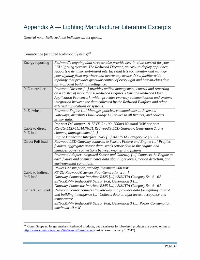
Page 37
Appendix A — Lighting Manufacturer Literature Excerpts
General note: Italicized text indicates direct quotes.
CommScope (acquired Redwood Systems)39
Energy reporting Redwood’s ongoing data streams also provide best-in-class control for your
LED lighting systems. The Redwood Director, an easy-to-deploy appliance,
supports a dynamic web-based interface that lets you monitor and manage
your lighting from anywhere and nearly any device. It’s a facility-wide
topology that provides granular control of every light and best-in-class data
for improved building intelligence.
PoE controller Redwood Director [...] provides unified management, control and reporting
on a cluster of more than 8 Redwood Engines. Hosts the Redwood Open
Application Framework, which provides two-way communication and systems
integration between the data collected by the Redwood Platform and other
external applications or systems.
PoE switch Redwood Engine [...] Manages policies, communicates to Redwood
Gateways, distributes low- voltage DC power to all fixtures, and collects
sensor data.
Per port DC output: 18–53VDC / 100–700mA Nominal 34W per port
Cable to direct
PoE load
RG-2G-LED-1CHANNEL Redwood® LED Gateway, Generation 2, one
channel, unprogrammed [...]
Engine Connector Interface RJ45 [...] ANSI/TIA Category 5e | 6 | 6A
Direct PoE load Redwood LED Gateway connects to Sensor, Fixture and Engine [...] Profiles
fixtures, aggregates sensor data, sends sensor data to the engine, and
manages power connections between engines and fixtures.
Redwood Adapter integrated Sensor and Gateway [...] Connects the Engine to
each fixture and communicates data about light levels, motion detection, and
environmental conditions.
Power Consumption, standby, maximum 500 mW
Cable to indirect
PoE load
RS-2G Redwood® Sensor Pod, Generation 2 [...]
Gateway Connector Interface RJ25 [...] ANSI/TIA Category 5e | 6 | 6A
SEN-3MP-W Redwood® Sensor Pod, Generation 3 [...]
Gateway Connector Interface RJ45 [...] ANSI/TIA Category 5e | 6 | 6A
Indirect PoE load Redwood Sensor connects to Gateway and provides data for lighting control
and building intelligence [...] Collects data on light levels, occupancy and
temperature.
SEN-3MP-W Redwood® Sensor Pod, Generation 3 [...] Power Consumption,
maximum 10 mW
39
CommScope no longer markets Redwood products, but datasheets for obsoleted products are posted online at
http://www.commscope.com/SiteSearch/?q=redwood (last accessed January 1, 2017).

Page 38

Page 39
Cree40
Energy reporting Cree SmartCast® PoE-enabled luminaires do more than just light your
spaces. [...] With the SmartCast® API, third-party apps can access data and
set controls on SmartCast® luminaires in the following ways [...] Detect and
record power consumption, down to the individual luminaire. [...] Advanced
power usage, energy savings, and lighting performance visualizations and
reporting.
Cree SmartCast® Manager PC Application for Setup, Dashboard and Energy
Analytics [...] Software is only operational when connected to SmartCast®
PoE lighting VLAN.
PoE controller The optional SmartCast® Link provides the connection between the lighting
network and third parties through the enterprise IP network while securely
separating and protecting critical systems for added protection. [...]The
SmartCast® API provides the ability for the lighting network to communicate
with and be controlled by other applications via the SmartCast® Link. Its
standards-based CoAP protocol is future-ready and developer-friendly
PoE switch Recommended network switches are Cisco Catalyst 4506-E, WS-C3850-24U-
S and WS-C3850-48U-S.
uPoE recommended to enable full fixture output. Compatible with PoE
(15.4W max) and PoE+ (30W max) at reduced output
Cable to direct
PoE load
Category 5e or 6a cables, shielded or unshielded. Finalize selection with
infrastructure provider based on run length or other installation details
A CAT5e or CAT6 Ethernet cable connects each Cree device to uPoE or
PoE+ switches that provide both low-voltage power to the lights and allow
two-way data communication across the lighting network and optionally,
building management systems, the Internet and the cloud.
Direct PoE load:
Luminaire with
sensors
SmartCast® PoE supports PoE, PoE+ and UPoE
• CR Series troffers 4000 lumens max on UPoE or 3000 lumens on PoE+
• KR Series downlights 2000 lumens max on UPoE or PoE+ (30W)
Luminaire Efficacy : 100 LPW *
Standby Power: <1.0W
fixtures share data with each other from their integrated occupancy and
daylight sensors while utilizing their embedded intelligence and sophisticated
algorithms to provide precisely the right amount of light at the right time
based on changing conditions within the building
Direct PoE load:
Sensor
POWER OVER ETHERNET INFRASTRUCTURE (BY OTHERS) [...] Delivers
power and data to the dimmer with one cable from PoE switch port to dimmer
Input Power: <1 Watt * Luminaire input power is not stated on product cutsheets, but can be calculated as the quotient of stated lumen
output and efficacy. Values calculated accordingly ranged from 1.6 to 40 W.
40
http://www2.cree.com/smartcast-landing-page, http://lighting.cree.com/products/controls/cree-smartcast-
technology

Page 40

Page 41
Igor 41
Energy reporting Granular control on a grand scale [...] Igor gives users the power of real-
time lighting control and monitoring at any level. Manage any part of your
lighting infrastructure through a single system.
Sensor data, energy data, system data, even daily backups are stored and
unified at Igor’s open cloud analytics platform, providing unprecedented
management.
PoE controller The Igor Gateway software communicates bi-directionally with the nodes to
control lighting levels for each space as well as receiving incoming
commands from sensors and other devices to improve occupant comfort and
optimize energy savings.
PoE switch The Category 5 or Cat5 cable, which replaces traditional power wiring,
transmits both power and data to smart fixtures such as LED lights from a
PoE switch such as the Cisco Catalyst 3850-X and 3560-X Series Power over
Ethernet (PoE) Switches.*
Cable to direct
PoE load
Cat5 combines both the power and data into one cable which saves the
builder tremendously on wiring costs.
PoE Input Connection: Unshielded female RJ45 jack for use with CAT5/6
cable to PSE device
Direct PoE load:
“network node”
IEEE 802.3at-2009 PD Type 2, Class 4, Compliant Input with LLDP
extensions for negotiating power above 30W using 4 pairs
With the flexibility of PoE and UPoE, we are now able to run up to 60 watts
of energy through Ethernet, supporting larger and more complex energy
needs.
The Igor Network node acts as an intelligent lighting hub by receiving power
& data from the network switch, and passing it downstream to the daisy-
chained device nodes via the Igor bus.
Bi-directional output connection used to power and communicate with Igor
device nodes
LED Driver Connections [...] External Sensor/Relay Connections [...] Wall
Switch Connections
Peak Operating Power: 60W
Nominal Standby Power: 2.0W
Cable to indirect
PoE load
Igor Bus Input / Output Connections: Two unshielded female RJ45 jacks for
use with CAT5/6 cable to Igor Network Node or other Device Nodes.
Indirect PoE load:
“device node”
Bi-directional input/output connections used to power and communicate with
other Igor nodes
LED Driver Connections [...] External Sensor/Relay Connections [...] Wall
Switch Connections
Peak Operating Power: 60W
Nominal Standby Power: 1.4W
* Manufacturer indicated by email February 14, 2017, that the Cisco Catalyst Digital Building Series Switch is
also compatible.
41
http://www.igor-tech.com/

Page 42

Page 43
Innovative Lighting 42
Energy reporting Analytics and ultra precise usage data provide enormous energy savings
potential and cloud based service means you can monitor your facility from
anywhere.
Bring your facility’s energy management into focus with fully customizable
lighting. Advanced scheduling, action sets, device management, data
collection and reporting are at your fingertips.
Real Time Energy Use Reporting
GENISYS will automatically track and chronicle energy data at an
unprecedented level. Wall switches and sensors are now active participants in
the work place, providing GENISYS with multiple data points from which to
extract behavioral data.
Addressability is yet another feature of the GENISYS PoE Lighting System
which incrementally reduces your lighting energy usage.
PoE controller
PoE switch System power for the GENISYS PoE Lighting System comes from a PoE+
(30W per port) or a UPoE (60W per port) networking switch. An open IEEE
infrastructure means that you can use the PoE Switch of your choice.
Cable to direct
PoE load From the switch, Ethernet cables are run to the Intellidrive.
Direct PoE load:
“Intellidrive”
IEEE Std 802.3at-2009 PD Type 2, Class 4, Compliant Input with LLDP
extensions for negotiating power above 30W using 4 pairs
When connected to a PoE enabled switch or midspan, the Intellidrive can both
receive power from, and exchange data with, this PoE source to power,
control, and monitor LED light fixtures. The Intellidrive also has a data port
for communicating with other control devices such as the Multi-Function
Sensor and the Dimmable Wall Switch.
As a smart lighting controller, the Intellidrive determines the type of light
fixture connected to it and determines the proper current to drive the light
fixture by its type.
Input Average Power: 51W [...] Peak Operating Power: 63W
Nominal Standby Power: 3W
Cable to indirect
PoE load
By utilizing the simple brilliance of an Ethernet cable to both power and
control LED fixtures, Power over Ethernet lighting provides ultimate
simplicity to an otherwise confusing Internet of Things (IoT). Every single
component in GENISYS PoE Lighting Systems is powered and controlled by
an Ethernet cable.*
Indirect PoE load
PoE Downlight [...] Energy (Watts) [...] 8.8W
PoE A2 Series Troffer [...] Energy (Watts) [...] 41.0W
PoE Wall Switch [...] Max Operating Power: 400mW
Typical Operating Power: 200mW
PoE Multi-Function Sensor [...] Max Operating Power: 170mW
Typical Operating Power: 150mW * The manufacturer clarified by email the Intellidrive does not source 802.3at or UPOE power.
42
www.genisyslighting.com, www.innovativelight.com/commercial-industrial-led-lighting/poe-led-lighting

Page 44
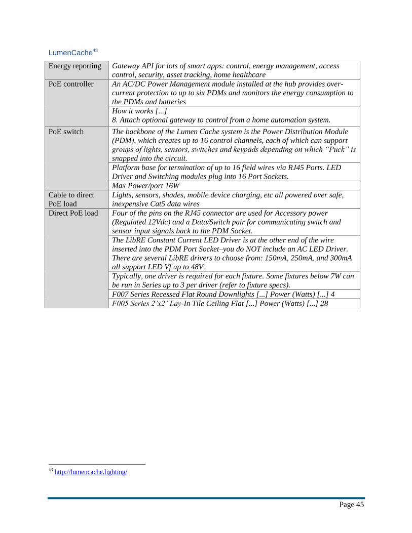
Page 45
LumenCache43
Energy reporting Gateway API for lots of smart apps: control, energy management, access
control, security, asset tracking, home healthcare
PoE controller An AC/DC Power Management module installed at the hub provides over-
current protection to up to six PDMs and monitors the energy consumption to
the PDMs and batteries
How it works [...]
8. Attach optional gateway to control from a home automation system.
PoE switch The backbone of the Lumen Cache system is the Power Distribution Module
(PDM), which creates up to 16 control channels, each of which can support
groups of lights, sensors, switches and keypads depending on which “Puck” is
snapped into the circuit.
Platform base for termination of up to 16 field wires via RJ45 Ports. LED
Driver and Switching modules plug into 16 Port Sockets.
Max Power/port 16W
Cable to direct
PoE load
Lights, sensors, shades, mobile device charging, etc all powered over safe,
inexpensive Cat5 data wires
Direct PoE load Four of the pins on the RJ45 connector are used for Accessory power
(Regulated 12Vdc) and a Data/Switch pair for communicating switch and
sensor input signals back to the PDM Socket.
The LibRE Constant Current LED Driver is at the other end of the wire
inserted into the PDM Port Socket–you do NOT include an AC LED Driver.
There are several LibRE drivers to choose from: 150mA, 250mA, and 300mA
all support LED Vf up to 48V.
Typically, one driver is required for each fixture. Some fixtures below 7W can
be run in Series up to 3 per driver (refer to fixture specs).
F007 Series Recessed Flat Round Downlights [...] Power (Watts) [...] 4
F005 Series 2’x2’ Lay-In Tile Ceiling Flat [...] Power (Watts) [...] 28
43
http://lumencache.lighting/

Page 46

Page 47
Lunera44
Energy reporting
PoE controller
PoE switch The first part of the solution is the PowerHive Power Distribution Control
Unit (PDCU) which centralizes AC-to-DC power conversion, emergency
battery, and dimming controls for up to 10 fixtures. All fixtures connected to a
PDCU can be controlled as group using standard 0-10V dimming protocols.
For individual fixture control and to take advantage of wired or wireless
occupancy and daylight sensors, the PDCU comes Lutron® EcoSystem
Enabled®.
When loss-of-power is detected, the PowerHive switches to battery mode and
signals the fixture to dim to 10%
0-10V dimming signals are bussed to the fixtures through the same CAT5
cable used for power distribution
Output Power 48V DC via (12) RJ45 Class II ports (400W Max)
Cable to direct
PoE load
By using low-voltage DC, the troffers can be simply tethered via Cat 5 cable
to the PDCU, which distributes 48V low voltage DC power and emergency
battery power to the troffer. In the same Cat 5 cable, dimming and switching
controls are transmitted, eliminating the need for additional wiring. The
standard RJ-45 terminator on the Cat 5 cable makes relocating a PowerHive
troffer as easy as unplugging a cord.
Direct PoE load The second part of the solution is the PowerHive low voltage DC LED troffer.
The PowerHive troffers [...] operate on 48V DC and are connected to the
PDCU via Cat 5 cable. Up to 10 troffers per PDCU receive operating and
emergency backup power, 0-10V dimming and occupancy/daylight sensing
control through a simple Cat 5 cable.
The PowerHive troffers are available with standard 0-10V dimming that is
ready to connect to various third-party controls or Lutron EcoSystem®
Enabled.
44
https://www.lunera.com

Page 48

Page 49
MHT Lighting45
Energy reporting features include a master control function which enables the user to manage
all system elements with a single button, or the individual granularity to
control every component one by one. The inspeXtor can chart kW
consumption, energy savings, and the ambient temperature simultaneously.
PoE controller The inspeXtor includes a rack mounted server which provides redundancy for
all lighting policies, as well as the ability to control single components
separately, via a unique tagging protocol.
PoE switch Powered by CISCO
Cable to direct
PoE load
Direct CAT5e connection from power source (Cisco)
Fitted with sensors and connected by low-voltage, category 5/6 cable, MHT
smart lighting solutions are connected to the internet, plug and play and data
capable right out of the box.
Direct PoE load MHT Lighting PoE NODE
Model No. MHTi-ND-60
Features:
POE++ enabled lighting control node
Cisco UPOE compatible with 52.7 Watts Class 4 response
Up to 51 Watts power supply
[...]
Internal Power consumption………………………………….. 0.5 Watts
[...]
IEEE POE standard………………………………………………….. 802.3at
LED TROFFER MHTi-VOL-SC SERIES [...]
Complete with Integrated Sensor [...]
Max Wattage [...] 52W
LED DOWN LIGHT MHTi-DL-SC SERIES [...]
Driver 25W Max [...]
Cable to indirect
PoE load
LED TROFFER MHTi-VOL-SC SERIES [...]
Category Cable
LED DOWN LIGHT MHTi-DL-SC SERIES [...]
Category Cable [...]
Wire Harness to Connect Up To Four Fixtures Per Port
Indirect PoE load inspeXtor- LED Driver
Model No. MHTi-DR-60
General Specifications:
Drives LED fixtures up to 52 Watts
[...]
Responds to MHTi™ based communication network
[...]
Off mode power consumption…………………… 0.05 Watts
LED DOWN LIGHT MHTi-DL-SC SERIES [...]
Complete with Non-Integrated Sensor
45
http://mhtlighting.com

Page 50

Page 51
Molex46
Energy reporting Transcend® Smart LED Driver Series [...] Integrated Power Monitoring [...]
Provides individual energy consumption feedback for each luminaire
The applications feed sensor data to a central host so you can measure real-
time energy consumption, air quality, temperature and more for increased
operational efficiency.
The network communication is based on CoAP and will allow an easy
convergence of IP infrastructure securely thanks to Cisco technology.
PoE controller At the heart of the Transcend system, the PoE Gateway distributes power and
connects luminaries, sensors and other devices to the Transcend manager
[...] The Transcend Lighting Software Tool-set provides support during the
complete lifecycle of a smart lighting control system, from design and
installation to live operation and building maintenance.
PoE switch Each Gateway is connected to a Cisco® Catalyst switch port with a
Category Cable, capable of receiving 60 watts using four pairs.
Cable to direct
PoE load
While CAT 5e, 24-gauge cable is the minimum that can be specified for a
PoE lighting system, as a best practice we recommend CAT 6, 23-gauge.
Direct PoE load:
“PoE Gateway”
The Transcend Gateway is a Cisco Universal Power over Ethernet (UPoE)
compliant device. [...]
UPoE IEEE802.3bt (compatible with PoE/PoE+) [...]
Input: IEEE802.3at/bt
The Transcend interface is optimized to deliver low voltage power and
reliable communication with lights, sensors and other devices.
It can aggregate data from the Transcend sensor node, wall dimmers and
other local controls.
Nominal Power Input 60W
Standby Power Consumption 0.5W
Cable to indirect
PoE load
The driver is powered and physically connected by the Transcend POE
Gateway with a rugged and reliable Transcend harness cable using a Molex
Micro-Fit 4-pin connection.
The Transcend System is also designed to optimize power/data distribution
and minimize the number of PoE ports. Daisy-chain fixture-to-fixture is
implemented with the Transcend Harness Device to Device.
Indirect PoE load:
driver, luminaire,
etc.
If the power requirement for a group of devices is below 50W, a single
Transcend PoE Gateway can power and control multiple drivers in a daisy-
chain configuration
Transcend® 2x2 LED Troffer Series [...] 42W
46
http://www.transcendled.com/

Page 52
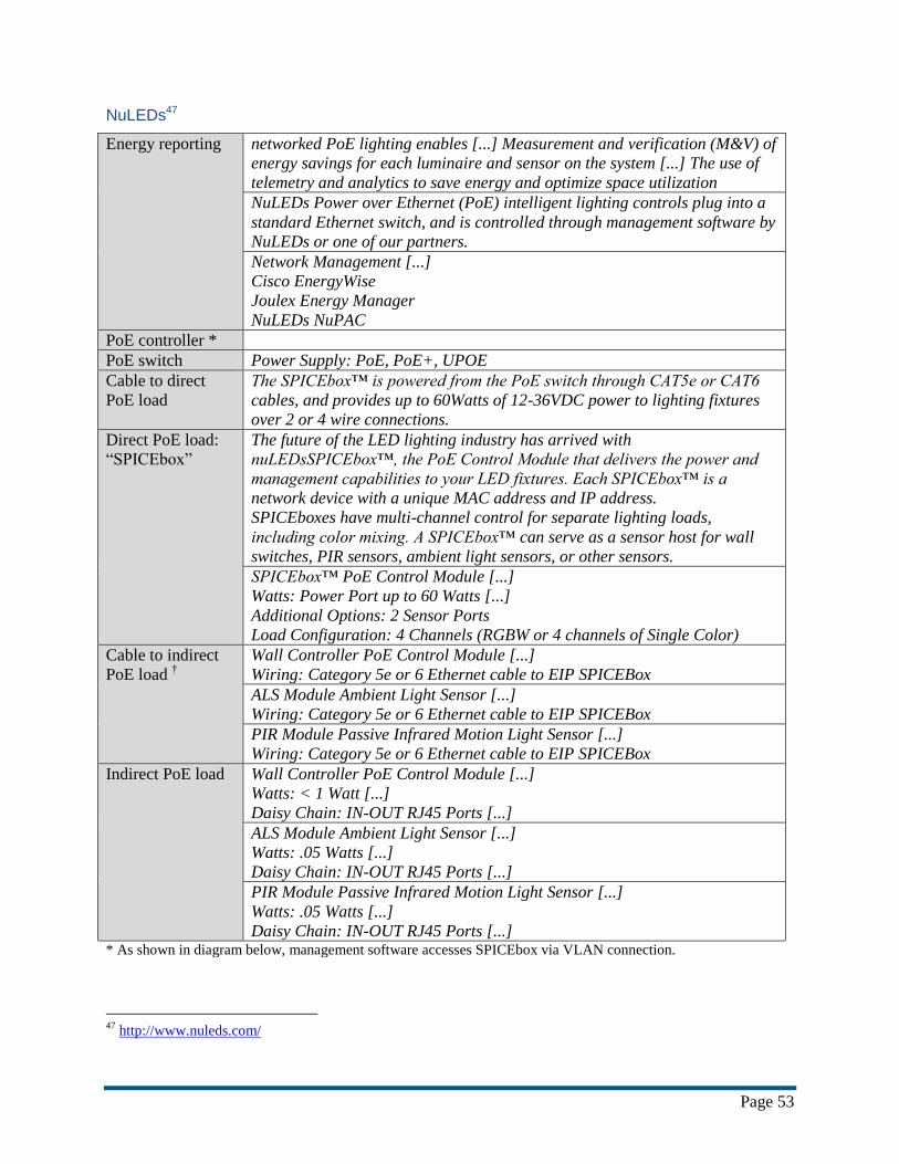
Page 53
NuLEDs47
Energy reporting networked PoE lighting enables [...] Measurement and verification (M&V) of
energy savings for each luminaire and sensor on the system [...] The use of
telemetry and analytics to save energy and optimize space utilization
NuLEDs Power over Ethernet (PoE) intelligent lighting controls plug into a
standard Ethernet switch, and is controlled through management software by
NuLEDs or one of our partners.
Network Management [...]
Cisco EnergyWise
Joulex Energy Manager
NuLEDs NuPAC
PoE controller *
PoE switch Power Supply: PoE, PoE+, UPOE
Cable to direct
PoE load
The SPICEbox™ is powered from the PoE switch through CAT5e or CAT6
cables, and provides up to 60Watts of 12-36VDC power to lighting fixtures
over 2 or 4 wire connections.
Direct PoE load:
“SPICEbox”
The future of the LED lighting industry has arrived with
nuLEDsSPICEbox™, the PoE Control Module that delivers the power and
management capabilities to your LED fixtures. Each SPICEbox™ is a
network device with a unique MAC address and IP address.
SPICEboxes have multi-channel control for separate lighting loads,
including color mixing. A SPICEbox™ can serve as a sensor host for wall
switches, PIR sensors, ambient light sensors, or other sensors.
SPICEbox™ PoE Control Module [...]
Watts: Power Port up to 60 Watts [...]
Additional Options: 2 Sensor Ports
Load Configuration: 4 Channels (RGBW or 4 channels of Single Color)
Cable to indirect
PoE load †
Wall Controller PoE Control Module [...]
Wiring: Category 5e or 6 Ethernet cable to EIP SPICEBox
ALS Module Ambient Light Sensor [...]
Wiring: Category 5e or 6 Ethernet cable to EIP SPICEBox
PIR Module Passive Infrared Motion Light Sensor [...]
Wiring: Category 5e or 6 Ethernet cable to EIP SPICEBox
Indirect PoE load Wall Controller PoE Control Module [...]
Watts: < 1 Watt [...]
Daisy Chain: IN-OUT RJ45 Ports [...]
ALS Module Ambient Light Sensor [...]
Watts: .05 Watts [...]
Daisy Chain: IN-OUT RJ45 Ports [...]
PIR Module Passive Infrared Motion Light Sensor [...]
Watts: .05 Watts [...]
Daisy Chain: IN-OUT RJ45 Ports [...] * As shown in diagram below, management software accesses SPICEbox via VLAN connection.
47
http://www.nuleds.com/

Page 54

Page 55
Philips48
Energy reporting Central management: Remotely and centrally monitor and manage all
connected light points, energy consumption, and occupancy data via software
With the help of PoE technology not only power and data can be delivered for
the luminaire over [...] a standard Ethernet cable but it also allows the
lighting system to be merged with the IT system. Like a computer, each fixture
has a unique network address for two-way Ethernet-based communications.
With integrated sensors, connected luminaires become points of intelligence
that share data on occupancy, activity patterns, and changes in temperature,
humidity, and daylight levels
PoE controller EnvisionGateway manages the Ethernet connection between Philips
connected lighting luminaires, Philips Dynalite devices and Philips
EnvisionManager end user software. [...] Inbuilt web server — Allows for
browser based control scenarios. [...] Inbuilt timeclock and schedule manager
allow the user to manage operation and task scheduling
PoE switch Standard IT switch: Provides power and data to the luminaires over a
Ethernet cable
LCN5228 PoE switch [...]
Star or ring topology can be supported with Spanning tree configuration [...]
PoE Output power per port (according IEEE802.3at standard: 30W – 34.2W)
Max.: 32W [...]
POWER-ETHERNET-MIB RFC 3621 [...]
PoE (poeStatusTemp, poeStatusVoltage poeStatusCurrent all per port):
Private MIB
Cable to direct
PoE load
Power Over Ethernet (PoE): Power and data over the same Ethernet cable
The 10M/100M/1000M Ethernet ports on the Philips PoE switch use standard
RJ 45 connectors of types: Cat5e/6/6A/7/7A conform AWG-24 – AWG-22.
[...]When connecting ports to 10BASE-T- and 100BASETX-
compatible devices, such as luminaires, and routers, it is allowed to use a four
twisted-pair, straight-through cable wired for 10BASE-T,
100BASE-TX and 1000BASE-T (Alternative B according IEEE802.3at
standard). Note: Be sure to use a four twisted-pair, Category 5 cable or
higher when connecting to a 10M/100M/1000M BASE-T-compatible device.
When connecting the switch to luminaires, straight-through cable-wiring must
be applied.
Direct PoE load 2EV EvoGrid recessed LED 2x2 with Power over ethernet (PoE) [...]
SYS: PoE daylight and motion Detection [...]
CAT6 RJ45 Connection
BoldPlay Direct/Indirect [...]
Integrated CAT5e cable allows for up to 24" drop between Luminaire and
Canopy. Mounting canopy provides RJ45 connection point for PoE network.
[...] Input Power: 22.2W [...] Standby power <0.9W
48
http://www.usa.lighting.philips.com/systems/connected-lighting-for-offices.html

Page 56

Page 57
Platformatics49 and PoE Illumination50
Energy reporting By converging lighting onto an IT communication backbone, it’s easy to add
lights, sensors and other devices needed to collect business relevant data. [...]
Platformatics Highlights: [...] Per light real-time energy monitoring, dimming
and tuning *
Lights work with existing network management and energy monitoring tools *
The Platformatics system is comprised of LED light fixtures, intelligent PoE
nodes, sensors, wall switches, area controllers, Ethernet switches, and cloud
based applications. [...] *
PoE controller The Platformatics Area Controller [...] The PAC is a server that houses the
Platformatics Software, and acts as a security and provisioning gateway for
the system. [...] The Platformatics Software can be accessed through any
desktop, laptop, or phone. *
PoE switch B-Tech Reduced Lighting Electric Use Over 70% [...] The system was
powered by a Cisco Catalyst 3850 UPoE Ethernet Switch. *
The Ethernet switch provides power to the lighting system and serves as the
communication hub for the PAC. *
Cable to direct
PoE load CAT5E+ Ethernet Cable *
Direct PoE load The Platformatics node supports multiple LED lights, device discovery,
granular dimming, sensors, and full RGB control. *
Each of our lights, from architectural tunable troffers (used in commercial
offices) to parking garage lights, is designed and thoroughly tested with
Platformatics’ nodes and Cisco UPOE Ethernet switches. †
This fixture supports full PoE (Power over Ethernet) integration and is
designed to work with Platformatics’ Intelligent lighting system. †
This fixture runs at 6 Watts †
This fixture runs at 50 Watts †
Cable to indirect
PoE load
18-20 Gauge Wire ‡
Indirect PoE load Many of our lights share a common Ethernet cable. While our high power
downlights and floods require 50 watts on a dedicated cable, our latest
parking garage light produces 1800 lumens and consumes only 12 watts. This
allows customers to power and control 4 lights on a single Ethernet run. † * Excerpts from Platformatics. † Excerpts from PoE Illumination.
‡ The diagram below indicates indirect PoE loads wired in parallel do not use Ethernet cabling.
49
http://platformatics.com/ 50
http://poeillumination.com/

Page 58

Page 59
References
ANSI. 2010. ANSI C12.20-2010. American National Standard for Electricity Meters—0.2 and 0.5
Accuracy Classes. Rosslyn: NEMA (National Electrical Manufacturers Association).
ANSI. 2014. ANSI ESVP Progress Report - Standardization Roadmap for Electric Vehicles, Version 2.0.
Washington: ANSI (American National Standards Institute).
ANSI. 2015. ANSI C82.16-2015. American National Standard for Light-Emitting Diode Drivers—
Methods of Measurement. Rosslyn: NEMA (National Electrical Manufacturers Association).
ANSI. 2016a. ANSI C12.1-2014. American National Standard for Electric Meters—Code for Electricity
Metering. Rosslyn: NEMA (National Electrical Manufacturers Association).
ANSI. 2016b. "PINS Corrections: BSR ICEA P-45-482-201x and BSR/NEMA ESM1-201x." ANSI
Standards Action, September 23, 2016.
ASTM. 2005. ASTM D4566-05e1, Standard Test Methods for Electrical Performance Properties of
Insulations and Jackets for Telecommunications Wire and Cable. West Conshohocken: ASTM
(American Society for Testing and Materials) International.
ATIS. 2013. ATIS-0600015.03.2013. Energy Efficiency For Telecommunications Equipment:
Methodology For Measurement And Reporting For Router And Ethernet Switch Products.
Washington: ATIS (Alliance for Telecommunications Industry Solutions).
BPA. 2015. Energy Efficiency Technology Roadmap. Volume 4: Electronics. March 2015. Portland:
BPA (Bonneville Power Administration).
Briggs, Jason. 2014. "Innovative Lighting and Igor develop PoE system to integrate lighting and
controls." LEDs Magazine.
Carlson, Steven. 2014. "Why the industry needs a PoE Logo Program." Cabling Installation &
Maintenance Magazine, October 6, 2014.
CE Pro. 2012. "NuLEDs Launches PoE Lighting Solution for LEDs." CE Pro.
CEC. 2013. Guidelines for California’s Solar Electric Incentive Programs (Senate Bill 1), Fifth Edition.
Sacramento: CEC (California Energy Commission ).
Cisco. 2004. Power over Ethernet: Cisco Inline Power and IEEE 802.3af. White Paper. San Jose: Cisco
Systems.
Cisco. 2008. Enhanced Power over Ethernet: Easier Deployment and Improved Mobility. San Jose: Cisco
Systems.
Cisco. 2011. Cisco EnergyWise Design Guide. Updated: Sep 02, 2011. San Jose: Cisco Systems.
Cisco. 2012. Cisco IOS Release Notes for Cisco EnergyWise, EnergyWise Version 2.8. Updated:Aug 06,
2012. San Jose: Cisco Systems.

Page 60
Cisco. 2014. Cisco Universal Power Over Ethernet: Unleash the Power of your Network. White Paper.
San Jose: Cisco Systems.
Cisco. 2016a. Cisco Digital Ceiling: Powering New Experiences and Insights. White Paper. San Jose:
Cisco Systems.
Cisco. 2016b. Network Powered Lighting Configuration Guide, Cisco IOS XE 3.7.0EX (Catalyst 3850
Switches). First Published: April 18, 2016. San Jose: Cisco Systems.
Cisco. 2017. Cisco Catalyst Digital Building Series Switches Data Sheet. San Jose: Cisco Systems.
Congdon, Herb. 2008. "568-C.0: The next generation of cabling standards." Cabling Installation &
Maintenance, September 1, 2008.
CPUC. 2016. California Solar Initiative Program Handbook, February 2016. San Francisco: CPUC
(California Public Utilities Commission).
Cree. 2016. Cree SmartCast PoE Technology: The Simplest, Most Intuitive Way to Get Intelligent
Lighting. CAT/SSHT-C063 Rev. Date: 05/10/16. Durham: Cree.
Darshan, Yair, and Kousalya Balasubramanian. 2015. "Type 4 System Power Parameters Analysis."
P802.3bt 4-Pair Power over Ethernet (4PPoE) March 2015 Meeting, Berlin, March 11, 2015.
Dewan, Shai. 2014. "Philips develops smartphone-controlled connected office lighting system." LEDs
Magazine, March 27, 2014.
DOE. 2014. 2014-10-09 Energy Conservation Program: Test Procedures for External Power Supplies;
Notice of proposed rulemaking. Washington: DOE (U.S. Department of Energy).
DOE. 2015. Appendix Z to Subpart B of Part 430—Uniform Test Method for Measuring the Energy
Consumption of External Power Supplies. edited by DOE (U.S. Department of Energy).
Washington: GPO (U.S. Government Publishing Office).
EMerge Alliance. 2016. "DC Metering TSC Formed." dcConnect. Official Newsletter of the EMerge
Alliance. IS004. Fall/Winter 2016 Edition, November 2016.
EPA. 2013a. ENERGY STAR® Program Requirements, Product Specification for Telephony, Final Test
Method, Rev. Nov-2013. Washington: US EPA (United States Environmental Protection
Agency).
EPA. 2013b. ENERGY STAR® Test Method for Small Network Equipment. Final Test Method, Rev.
Nov-2013. Washington: US EPA (United States Environmental Protection Agency).
EPA. 2014a. ENERGY STAR® Product Specification for Small Network Equipment Eligibility Criteria.
Version 1.0, Rev. Oct-2014. Washington: US EPA (United States Environmental Protection
Agency).
EPA. 2014b. ENERGY STAR® Product Specification for Telephony. Eligibility Criteria, Version 3.0,
Rev. Oct-2014. Washington: US EPA (United States Environmental Protection Agency).
EPA. 2016a. ENERGY STAR Program Requirements for Large Network Equipment – Eligibility
Criteria, Version 1.0. Washington: US EPA (United States Environmental Protection Agency).

Page 61
EPA. 2016b. ENERGY STAR® Program Requirements, Product Specification for Large Network
Equipment, Test Method, Rev. Jan-2016. Washington: US EPA (United States Environmental
Protection Agency).
Ethernet Alliance. 2016. 2016 Ethernet Roadmap. Beaverton: Ethernet Alliance.
Halper, Mark. 2016. "Cisco marches into connected lighting with new partners and new PoE installations
(UPDATED)." LEDs Magazine, February 17, 2016.
Halper, Mark. 2017. "Cisco stokes PoE lighting push with dedicated Ethernet switch, signs up Marriott "
LEDs Magazine.
HDBaseT. 2011. Introduction to Power Over HDBaseT. HDBaseT Alliance.
ICEA. 2012. ICEA S-90-661, 2012 Edition. Category 3, 5, & 5e Individually Unshielded Twisted Pair
Indoor Cables (With Or Without An Overall Shield) For Use In General Purpose And Lan
Communication Wiring Systems Technical Requirements. Alpharetta: ICEA (Insulated Cable
Engineers Association).
IEC. 1990. IEC 60603-7:1990, Connectors for frequencies below 3 MHz for use with printed boards, Part
7: Detail specification for connectors, 8-way, including fixed and free connectors with common
mating features, with assessed quality. Geneva: IEC (International Electrotechnical Commission).
IEC. 2011. IEC 62301, Edition 2.0, 2011-01. Household electrical appliances - Measurement of standby
power. Geneva: IEC (International Electrotechnical Commission).
IEC. 2015. Report to Council from the Council Board (CB) following its meeting in Minsk on 2015-10-
14. Geneva: IEC (International Electrotechnical Commission).
IEEE. 1985. ANSI/IEEE Std 802.3-1985, IEEE Standards for Local Area Networks: Carrier Sense
Multiple Access with Collision Detection (CSMAKD) Access Method and Physical Layer
Specifications. New York: IEEE (Institute of Electrical and Electronics Engineers).
IEEE. 2000. IEEE Standard 1515-2000 - IEEE Recommended Practice for Electronic Power Subsystems:
Parameter Definitions, Test Conditions, and Test Methods. New York: IEEE (Institute of
Electrical and Electronics Engineers).
IEEE. 2003. IEEE Std 802.3af-2003 (Amendment to IEEE Std 802.3-2002, including IEEE Std 802.3ae-
2002). IEEE Standard for Information technology--Telecommunications and information
exchange between systems--Local and metropolitan area networks--Specific requirements. Part 3:
CSMA/CD Access Method and Physical Layer Specifications. Amendment: DTE Power via
MDI. New York: IEEE (Institute of Electrical and Electronics Engineers).
IEEE. 2009. IEEE Std 802.3at-2009 (Amendment to IEEE Std 802.3-2008). IEEE Standard for
Information technology--Telecommunications and information exchange between systems--Local
and metropolitan area networks--Specific requirements. Part 3: CSMA/CD Access Method and
Physical Layer Specifications. Amendment 3: DTE Power via the MDI Enhancements. New
York: IEEE (Institute of Electrical and Electronics Engineers).
IEEE. 2011. IEEE Std 802.3.1™-2011, IEEE Standard for Management Information Base (MIB)
Definitions for Ethernet. New York: IEEE (Institute of Electrical and Electronics Engineers).

Page 62
IEEE. 2013a. IEEE 802.3 4PPoE Objectives, Version 2.0. New York: IEEE (Institute of Electrical and
Electronics Engineers).
IEEE. 2013b. IEEE Std 802.3.1-2013. IEEE Standard for Management Information Base (MIB)
Definitions for Ethernet. New York: IEEE (Institute of Electrical and Electronics Engineers).
IEEE. 2015a. IEEE Std 802.3-2015. IEEE Standard for Ethernet. New York: IEEE (Institute of Electrical
and Electronics Engineers).
IEEE. 2015b. IEEE Std 2030.1.1-2015. IEEE Standard Technical Specifications of a DC Quick Charger
for Use with Electric Vehicles. New York: IEEE (Institute of Electrical and Electronics
Engineers).
IEEE. 2015c. IEEE to Adopt the HDBaseT Standard for Ultra-High-Definition Digital Connectivity. In
News & Events: Press Releases. New York: IEEE (Institute of Electrical and Electronics
Engineers).
IEEE. 2016a. IEEE 802.3 Ethernet Working Group - 5 Criteria, Version 2.1. New York: IEEE (Institute
of Electrical and Electronics Engineers).
IEEE. 2016b. IEEE P802.3bt D1.7 4-Pair Power-over-Ethernet 10th Task Force review comments,
5/4/2016. New York: IEEE (Institute of Electrical and Electronics Engineers).
IEEE. 2016c. IEEE P802.3bt D2.0 4-Pair PoE Initial Working Group ballot comments, 9/16/2016. New
York: IEEE (Institute of Electrical and Electronics Engineers).
IEEE. 2016d. IEEE Std 525-2016, IEEE Guide for the Design and Installation of Cable Systems in
Substations. New York: IEEE (Institute of Electrical and Electronics Engineers).
IES. 2008. IES LM-79-08. Approved Method: Electrical and Photometric Measurements of Solid-State
Lighting Products. New York: IES (Illuminating Engineering Society).
IES. 2012a. IES LM-28-12. Approved Method: IES Guide for the Selection, Care and Use of Electrical
Instruments in the Photometric Laboratory. New York: IES (Illuminating Engineering Society).
IES. 2012b. IES LM-82-12. Approved Method: Characterization of LED Light Engines and LED Lamps
for Electrical and Photometric Properties as a Function of Temperature. New York: IES
(Illuminating Engineering Society).
IES. 2017. "2016 Progress Report." LD+A, January 2017.
ISO. 1993. ISO/IEC Guide 98:1993. Guide to the expression of uncertainty in measurement (GUM).
Geneva: ISO (International Organization for Standardization).
Jacobson, Julie. 2012. "LumenCache Launches End-to-End Low-Voltage LED Lighting." CE Pro, June
26, 2012.
Law, David. 2016a. "Liaison to ISO/IEC/JTC1 SC25 WG3. IEEE 802.3 Ethernet Task Force Informal
Communication." January 21, 2016.

Page 63
Law, David. 2016b. P802.3bt. Modification to a Previously Approved PAR for an Amendment. PAR
Approval Date: 12-May-2016. New York: IEEE (Institute of Electrical and Electronics
Engineers).
LEDs Magazine. 2010. "Redwood Systems brings network-powered approach to LED office lighting."
LEDs Magazine, Mar 8, 2010.
Lunera. 2013. Lunera PowerHive: A LED DC Troffer and Controls Solution. Santa Clara: Lunera.
MHT. 2014. LED Down Light: MHTL-DL-RC Series. Rev Date: Apr-2014. Staten Island: MHT
Lighting.
MHT. 2016. LED Down Light: MHTi-DL-SC Series. Rev: October 2016. Staten Island: MHT Lighting.
Microsemi. 2011. Understanding 802.3at: PoE Plus Standard Increases Available Power. Aliso Viejo:
Microsemi Corporation.
Microsemi. 2016. Next-Generation PoE: IEEE 802.3bt. White Paper, Revision 1.0. Aliso Viejo:
Microsemi Corporation.
Molex. 2016. Transcend PoE Gateway. Order No. 987651-4292. USA/0k/GF/2016.02. Lisle: Molex.
NCSL. 1997. ANSI/NCSL Z540-2-1997. U.S. Guide to the Expression of Uncertainty in Measurement.
Boulder: NCSL (National Conference of Standards Laboratories) International.
NEMA-ICEA. 2013. ANSI/NEMA WC 66/ICEA S-116-732-2013. Standard for Category 6 and 6A, 100
Ohm, Individually Unshielded Twisted Pairs, Indoor Cables (With or Without an Overall Shield)
for Use in LAN Communication Wiring Systems. Rosslyn: NEMA (National Electrical
Manufacturers Association).
NuLEDs. 2016. The Power of Innovation - SPICEbox PoE Control Module. Carlsbad: NuLEDs.
Randy Ivans, Anthony Tassone. 2015. Fact-Finding Study on Powering Over Data Cables. Northbrook:
UL (Underwriters Laboratories).
Redwood Systems. 2010. Redwood Engine Preliminary Product Specification. Fremont: Redwood
Systems.
Redwood Systems. 2012. Redwood System Installation Guide, version 2.1. Fremont: Redwood Systems.
Redwood Systems. 2013. Engine 3 - Model 4834 Installation Instructions. Hickory: CommScope.
Shulman, Michael. 2015. Power over Ethernet Lighting – Evolution or Revolution? Northbrook: UL
(Underwriters Laboratories).
Sifos. 2016a. PDA-602A. PoE Powered Device Analyzer. IEEE 802.3at Power-over-Ethernet. Product
Overview. Tewksbury: Sifos Technologies.
Sifos. 2016b. PowerSync Analyzer Application Note. 4-Pair PSE Testing with the PSA/PSL-3102. 4-Pair
PoE: Common Questions About 4-Pair PSE’s Today. Tewksbury: Sifos Technologies.

Page 64
Silvertel. 2012. Ag6700 230W Power Sourcing Module Datasheet V1.2 August 2012. Newport, UK:
Silvertel (Silver Telecom).
Stewart, Heath. 2011. "LTPoE++ Extends PoE to 90W with Reliable and Easy-to-Use Standard." LT
Journal of Analog Innovation, July 2011.
Strategen/Arup. 2014. Direct Current Scoping Study. Opportunities for Direct Current Power in the Built
Environment. Prepared for Pacific Gas and Electric, on behalf of the Department of Energy
Building Technologies Office. Washington: DOE (U.S. Department of Energy).
Strong, Wendell. 2017. Innovative Lighting's GENISYS Launches New Software Suite, Website. New
York: Newswire.
Taylor, Barry N., Chris E. Kuyatt. 1994. NIST Technical Note 1297, 1994 Edition. Guidelines for
Evaluating and Expressing the Uncertainty of NIST Measurement Results. Gaithersburg: NIST
(National Institute of Standards and Technology).
Thomas, Brinda A., Inês L. Azevedo, and Granger Morgan. 2012. "Edison Revisited: Should we use DC
circuits for lighting in commercial buildings?" Energy Policy 45:399-411. doi:
http://dx.doi.org/10.1016/j.enpol.2012.02.048.
TIA. 1995. ANSI/TIA/EIA-568-A-1995, Commercial Building Telecommunications Cabling Standard.
Arlington: TIA (Telecommunications Industry Association).
TIA. 2009a. ANSI/TIA-568-C.2, Revision C. Balanced Twisted-Pair Telecommunications Cabling and
Components Standards. Arlington: TIA (Telecommunications Industry Association).
TIA. 2009b. TIA TSB-184, 2009 Edition. Guidelines for Supporting Power Delivery Over Balanced
Twisted-Pair Cabling. Arlington: TIA (Telecommunications Industry Association).
TIA. 2016a. TIA-1152-A, Requirements for Field Test Instruments and Measurements for Balanced
Twisted-Pair Cabling, November 10, 2016. Arlington: TIA (Telecommunications Industry
Association).
TIA. 2016b. TIA Issues Call for Interest on new Project for Balanced Twisted-Pair Telecommunications
Cabling and Components Standard In TIA Press Releases. Arlington: TIA (Telecommunications
Industry Association).
UL. 2015a. Fact Finding Report on Power over Local Area Network Type Cables (4-Pair Data /
Communications Cables) <with errata 1 revisions>. Washington: SPI (Society of the Plastics
Industry).
UL. 2015b. UL 2108, Edition 2. Standard for Low Voltage Lighting Systems. Northbrook: UL
(Underwriters Laboratories).
UL. 2015c. UL Issues First Limited Power (LP) Certification to General Cable’s GenSPEED® Cables.
Mark helps ensure safe and efficient thermal performance in high power (>60 watts) Power-over-
LAN applications. In NEWSROOM Press Releases. Northbrook: UL (Underwriters Laboratories).
Warren, Carol. 2011. "Lunera Lighting reveals Redwood Systems-ready luminaires." LEDs Magazine,
September 21, 2011.

Page 65
Wright, Maury. 2016. "Eaton partners with NuLEDs on PoE technology for connected SSL." LEDs
Magazine, July 26, 2016.
Ziegenfus, Scott. 2016. "Lighting with Power over Ethernet (PoE), an IT Convergence." LED Specifier
Summit Northwest, Seattle, WA, September 22, 2016.