Embed Size (px)
Citation preview

Point-Mass Dynamics and Aerodynamic/Thrust Forces !Robert Stengel, Aircraft Flight Dynamics, !
MAE 331, 2016
•! Properties of atmosphere and dynamic pressure •! Frames of reference for position and motion•! Velocity and momentum in inertial frame•! Newton s three laws of motion and “flat-earth” gravitation•! Longitudinal and lateral-directional axes of airplane•! Lift and drag expressed using non-dimensional coefficients•! Simplified equations for longitudinal motion•! Aircraft powerplants and thrust
Copyright 2016 by Robert Stengel. All rights reserved. For educational use only.http://www.princeton.edu/~stengel/MAE331.html
http://www.princeton.edu/~stengel/FlightDynamics.html
Learning Objectives
Reading:!Flight Dynamics !
Introduction, 1-27!The Earth’s Atmosphere, 29-34!
Kinematic Equations, 38-53!Forces and Moments, 59-65!
Introduction to Thrust, 103-107!
1
Assignment #2"due: End of day, Sept 30, 2016!
•! Compute the trajectory of a balsa glider!•! Simulate equations of motion!•! Compare to the actual flight of the glider
(Assignment #1)!•! Similar to flight of paper airplane!•! 2-person team assignment !
2

The Atmosphere!
3
•! Air density and pressure decay exponentially with altitude
•! Air temperature and speed of sound are piecewise-linear functions of altitude
Properties of the Lower Atmosphere*
TroposphereTropopause
Stratosphere
* 1976 US Standard Atmosphere4

Air Density, Dynamic Pressure, and Mach Number
! = Air density, functionof height= !sealevele
"#h = !sealevele#z
Vair = vx2 + vy
2 + vz2!" #$air1/2= vTv!" #$air
1/2= Airspeed
Dynamic pressure = q = 1
2! h( )Vair2 ! "qbar"
Mach number = Vaira h( ) ; a = speed of sound, m/s
5
!sealevel = 1.225kg/m3; " = 1/ 9,042m
True airspeed must increase as altitude increases to maintain constant dynamic pressure
Contours of Constant Dynamic Pressure,
Weight = Lift =CL12!Vair
2 S =CLqS•! In steady, cruising flight,
q
6

Wind: Motion of the AtmosphereZero wind at Earth s surface = Rotating air mass
Wind measured with respect to Earth s rotating surface
Wind Velocity Profiles vary over Time
Airspeed = Airplane s speed with respect to air massEarth-relative velocity = Wind velocity ± True airspeed [vector] 7
!!iiss""rriiccaall FFaacc""iiddss•! Henri Pitot: Pitot tube (1732)
•! Benjamin Robins: Whirling arm "wind tunnel (1742)
•! Papers on applied aerodynamics (1809-1810)
•! Triplane glider carrying 10-yr-old boy (1849)
•! Monoplane glider carrying coachman (1853)
–! Cayley's coachman had a steering oar with cruciform blades
Sir George Cayley
8
•! Sketched "modern" airplane configuration (1799)
•! Hand-launched glider (1804)

Equations of Motion for a Particle (Point Mass)!
9
Newtonian Frame of Reference!! Newtonian (Inertial) Frame of
Reference!! Unaccelerated Cartesian frame:
origin referenced to inertial (non-moving) frame
!! Right-hand rule!! Origin can translate at constant
linear velocity!! Frame cannot rotate with respect
to inertial origin
Translation changes the position of an object
r =xyz
!
"
###
$
%
&&&
!! Position: 3 dimensions!! What is a non-moving frame?
10

Velocity and Momentum !! Velocity of a particle
v = dxdt
= !x =!x!y!z
!
"
###
$
%
&&&=
vxvyvz
!
"
####
$
%
&&&&
!! Linear momentum of a particle
p = mv = mvxvyvz
!
"
####
$
%
&&&&
where m = mass of particle11
Inertial Velocity Expressed in Polar Coordinates
Polar Coordinates Projected on a Sphere
! : Vertical Flight Path Angle, rad or deg" : Horizontal Flight Path Angle (Heading Angle), rad or deg
12

Newton s Laws of Motion: !Dynamics of a Particle
!! First Law: If no force acts on a particle,!! it remains at rest or !! continues to move in a straight line at
constant velocity, as observed in an inertial reference frame
!! Momentum is conserved
ddt
mv( ) = 0 ; mv t1= mv t2
13
Newton s Laws of Motion: !Dynamics of a Particle
ddt
mv( ) = m dvdt
= F ; F =fxfyfz
!
"
####
$
%
&&&&
!! Second Law: A particle of fixed mass acted upon by a force !! changes velocity with acceleration proportional to
and in the direction of the force, as observed in an inertial frame;
!! The ratio of force to acceleration is the mass of the particle:
!dvdt
=1mF =
1mI3F =
1 / m 0 00 1 / m 00 0 1 / m
"
#
$$$
%
&
'''
fxfyfz
"
#
$$$$
%
&
''''
F = ma
14

Newton s Laws of Motion: !Dynamics of a Particle
!! Third Law!! For every action, there is an equal and opposite
reaction
Force on Rocket = Force on Exhaust Gasses15
Equations of Motion for a Particle: Position and Velocity
dvdt
= !v =!vx!vy!vz
!
"
####
$
%
&&&& I
= 1mF =
1/m 0 00 1/m 00 0 1/m
!
"
###
$
%
&&&
fxfyfz
!
"
####
$
%
&&&& I
drdt
= !r =!x!y!z
!
"
###
$
%
&&&I
= v =vxvyvz
!
"
####
$
%
&&&& I
FI =fxfyfz
!
"
####
$
%
&&&& I
= Fgravity + Faerodynamics + Fthrust!" $% I
Rate of change of position
Rate of change of velocity
Force vector
16

Integration for Velocity with Constant Force
dv t( )dt
= !v t( ) = 1mF =
fx mfy m
fz m
!
"
####
$
%
&&&&
=axayaz
!
"
####
$
%
&&&&
v T( ) = dv t( )dt
dt0
T
! + v 0( ) = 1mFdt
0
T
! + v 0( ) = adt0
T
! + v 0( )
vx T( )vy T( )vz T( )
!
"
####
$
%
&&&&
=
fx mfy m
fz m
!
"
####
$
%
&&&&
dt0
T
' +
vx 0( )vy 0( )vz 0( )
!
"
####
$
%
&&&&
=
axayaz
!
"
####
$
%
&&&&
dt0
T
' +
vx 0( )vy 0( )vz 0( )
!
"
####
$
%
&&&&17
Differential equation
Integral
Integration for Position with Varying Velocity
dr t( )dt
= !r t( ) = v t( ) =!x t( )!y t( )!z t( )
!
"
####
$
%
&&&&
=
vx t( )vy t( )vz t( )
!
"
####
$
%
&&&&
r T( ) = dr t( )dt
dt0
T
! + r 0( ) = v t( )dt0
T
! + r 0( )
x T( )y T( )z T( )
!
"
####
$
%
&&&&
=
vx t( )vy t( )vz t( )
!
"
####
$
%
&&&&
dt0
T
' +
x 0( )y 0( )z 0( )
!
"
####
$
%
&&&&
18
Differential equation
Integral
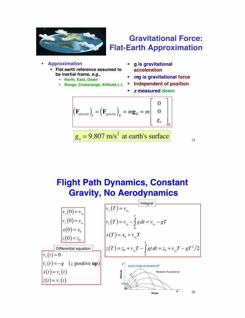
Gravitational Force:!Flat-Earth Approximation
!! g is gravitational acceleration
!! mg is gravitational force!! Independent of position!! z measured down
Fgravity( )I = Fgravity( )E = mgE = m00go
!
"
###
$
%
&&&E
!! Approximation!! Flat earth reference assumed to
be inertial frame, e.g.,!! North, East, Down!! Range, Crossrange, Altitude (–)
go ! 9.807 m/s2 at earth's surface19
Flight Path Dynamics, Constant Gravity, No Aerodynamics
!vx t( ) = 0!vz t( ) = !g z positive up( )!x t( ) = vx t( )!z t( ) = vz t( )
vx 0( ) = vx0vz 0( ) = vz0x 0( ) = x0z 0( ) = z0
vx T( ) = vx0vz T( ) = vz0 ! gdt
0
T
" = vz0 ! gT
x T( ) = x0 + vx0T
z T( ) = z0 + vz0T ! gt dt0
T
" = z0 + vz0T ! gT 2 2
20
Differential equation
Integral

MATLAB Scripts for Flat-Earth Trajectory, No Aerodynamics
gg == 99..88;; tt == 00::00..11::4400;; vvxx00 == 1100;; vvzz00 == 110000;; xx00 == 00;; zz00 == 00;; vvxx11 == vvxx00;; vvzz11 == vvzz00 –– gg**tt;; xx11 == xx00 ++ vvxx00**tt;; zz11 == zz00 ++ vvzz00**tt -- 00..55**gg**tt..** tt;;
ttssppaann == 4400;;xxoo == [[1100;;110000;;00;;00]];;[[tt11,,xx11]] == ooddee4455((''FFllaattEEaarrtthh'',,ttssppaann,,xxoo));;
ffuunnccttiioonn xxddoott == FFllaattEEaarrtthh((tt,,xx)) %% xx((11)) == vvxx%% xx((22)) == vvzz%% xx((33)) == xx%% xx((44)) == zz gg == 99..88;; xxddoott((11)) == 00;; xxddoott((22)) == --gg;; xxddoott((33)) == xx((11));; xxddoott((44)) == xx((22));; xxddoott == xxddoott'';;eenndd
Analytical Solution Numerical SolutionCalling Routine
Equations of Motion
21
Flight Path with Constant Gravity and No Aerodynamics
22

Aerodynamic Force on an Airplane
FI =XYZ
!
"
###
$
%
&&&E
=CX
CY
CZ
!
"
###
$
%
&&&E
12'Vair
2 S
=CX
CY
CZ
!
"
###
$
%
&&&E
q S
Referenced to the Earth, not the aircraft
Earth-Reference Frame Body-Axis Frame Wind-Axis Frame
FB =CX
CY
CZ
!
"
###
$
%
&&&B
q S FV =CD
CY
CL
!
"
###
$
%
&&&q S
Aligned with the aircraft axes
Aligned with and perpendicular to the direction of motion
23
Non-Dimensional Aerodynamic Coefficients
Body-Axis Frame Wind-Axis Frame
CX
CY
CZ
!
"
###
$
%
&&&B
=axial force coefficientside force coefficientnormal force coefficient
!
"
###
$
%
&&&
CD
CY
CL
!
"
###
$
%
&&&=
drag coefficientside force coefficientlift coefficient
!
"
###
$
%
&&&
•! Functions of flight condition, control settings, and disturbances, e.g., CL = CL(!, M, !E)
•! Non-dimensional coefficients allow application of sub-scale model wind tunnel data to full-scale airplane
24

u(t) : axial velocityw(t) :normal velocityV t( ) :velocity magnitude! t( ) : angle of attack" t( ) : flight path angle#(t) :pitch angle
•! along vehicle centerline•! perpendicular to centerline•! along net direction of flight•! angle between centerline and direction of flight•! angle between direction of flight and local horizontal•! angle between centerline and local horizontal
Longitudinal Variables
! = " #$ (with wingtips level)
25
Lateral-Directional Variables
!(t) :sideslip angle" (t) :yaw angle# t( ) :heading angle$ t( ) : roll angle
•! angle between centerline and direction of flight•! angle between centerline and local horizontal•! angle between direction of flight and compass reference
(e.g., north)•! angle between true vertical and body z axis
! =" + # (with wingtips level)
26

Visionaries and Theorists•! 1831: Thomas Walker
–! Various glider concepts–! Tandem-wing design
influenced Langley
!!iiss""rriiccaall FFaacc""iiddss•! 1843: William Henson & John
Stringfellow –! Aerial steam carriage concept–! Vision of commercial air
transportation (with Marriott and Columbine, The Aerial Transit Company)
27
Introduction to Lift and Drag!
28

Lift and Drag are Referenced to Velocity Vector
•! Drag components sum to produce total drag–! Parallel and opposed to velocity vector–! Skin friction, pressure differentials
•! Lift components sum to produce total lift–! Perpendicular to velocity vector–! Pressure differential between upper and lower surfaces
Lift =CL12!Vair
2 S " CL0+#CL
#$$
%
&'(
)*12!Vair
2 S
Drag =CD12!Vair
2 S " CD0+#CL
2$% &'12!Vair
2 S
29
2-D Aerodynamic Lift•! Fast flow over top + slow flow over bottom = Mean flow +
Circulation•! Speed difference proportional to angle of attack•! Stagnation points at leading and trailing edges
•! Kutta condition: Aft stagnation point at sharp trailing edge
StreamlinesInstantaneous tangent to velocity vector
Lift =CL12!Vair
2 S " CLwing+CLfuselage
+CLtail( ) 12 !Vair2 S " CL0
+#CL
#$$
%
&'(
)*qS
30
StreaklinesLocus of particles passing through points
Dye injected at fixed points
http://www.diam.unige.it/~irro/profilo_e.html

3-D Lift
Inward flow over upper surfaceOutward flow over lower surface
Bound vorticity of wing produces tip vortices
Inward-Outward Flow
Tip Vortices
31
32

2-D vs. 3-D LiftIdentical Chord SectionsInfinite vs. Finite Span
Finite aspect ratio reduces lift slope
What is aspect ratio?
Talay, NASA-SP-367 33
Aerodynamic Drag
•! Drag components–! Parasite drag (friction, interference, base pressure
differential)–! Wave drag (shock-induced pressure differential)–! Induced drag (drag due to lift generation)
•! In steady, subsonic flight–! Parasite (form) drag
increases as V2
–! Induced drag(due to lift) proportional to 1/V2
–! Total drag minimized at one particular airspeed
Drag = CD12!Vair
2 S " CDp+CDw
+CDi( ) 12 !Vair2 S " CD0+ #CL
2$% &'qS
34

•! 1868: Jean Marie Le Bris–! Artificial Albatross glides a short distance •! 1891-96: Hang-glider flights
–! Otto Lilienthal–! Chanute, Pilcher, ...
•! 1890: Clement Ader–! Steam-powered Eole hops
•! 1894: Sir Hiram Maxim–! Steam-powered biplane hops–! Vertical gyro/servo control of the
elevator
•! 1884: Alexander Mozhaisky's steam-powered manned airplane
–! brief hop off the ground
•! 1874: Felix du Temple's hot-air engine manned monoplane
–! Flies down a ramp
!!iiss""rriiccaall FFaacc""iiddss
35
2-D Equations of Motion with Aerodynamics and Thrust!
36

2-D Equations of Motion for a Point Mass
!x!z!vx!vz
!
"
#####
$
%
&&&&&
=
vxvzfx /mfz /m
!
"
#####
$
%
&&&&&
=
0 0 1 00 0 0 10 0 0 00 0 0 0
!
"
####
$
%
&&&&
xzvxvz
!
"
#####
$
%
&&&&&
+
0 00 01/m 00 1/m
!
"
####
$
%
&&&&
CT cos' +CXI( )qS(CT sin' +CZI( )qS +mgo
!
"
###
$
%
&&&
•! Motions restricted to vertical plane•! Inertial frame, wind = 0•! z positive down, flat-earth assumption•! Point-mass location coincides with aircraft’s center of mass
q = 12! z( ) vx2 + vz2( )
CT = Thrust coefficient! = Pitch angle
37
Transform Velocity from Cartesian to Polar Coordinates
!x!z
!
"#
$
%& =
vxvz
!
"##
$
%&&=
V cos'(V sin'
!
"##
$
%&&
)V'
!
"##
$
%&&=
!x2 + !z2
( sin(1 !zV
*+,
-./
!
"
####
$
%
&&&&
=vx2 + vz
2
( sin(1 vzV
*+,
-./
!
"
####
$
%
&&&&
!V!!
"
#$$
%
&''=
ddt
vx2 + vz
2
( ddtsin(1 vz
V)*+
,-.
"
#
$$$$
%
&
''''
Inertial axes -> wind axes and back
Rates of change of velocity and flight path angle
38

Longitudinal Point-Mass Equations of Motion
!x(t) = vx =V (t)cos! (t)!z(t) = vz = "V (t)sin! (t)
!V (t) =CT cos# "CD( ) 1
2$ z( )V 2 (t)S "mgo sin! (t)
m
!! (t) =CT sin# +CL( ) 1
2$ z( )V 2 (t)S "mgo cos! (t)
mV (t)
x : rangez : –height (altitude)V :velocity! : flight path angle
39
Steady, Level (i.e., Cruising) Flight
!x(t) = vx =Vcruise!z(t) = vz = 0
0 =CT !CD( ) 1
2" z( )Vcruise2 S
m
0 =CL12" z( )Vcruise2 S !mg z( )
mVcruise
In steady, level flight with cos " ~ 1, sin " ~ 0Thrust = Drag, Lift = Weight
40

Introduction to Aeronautical Propulsion!
41
Internal Combustion Reciprocating Engine
Linear motion of pistons converted to rotary motion to drive propeller
42
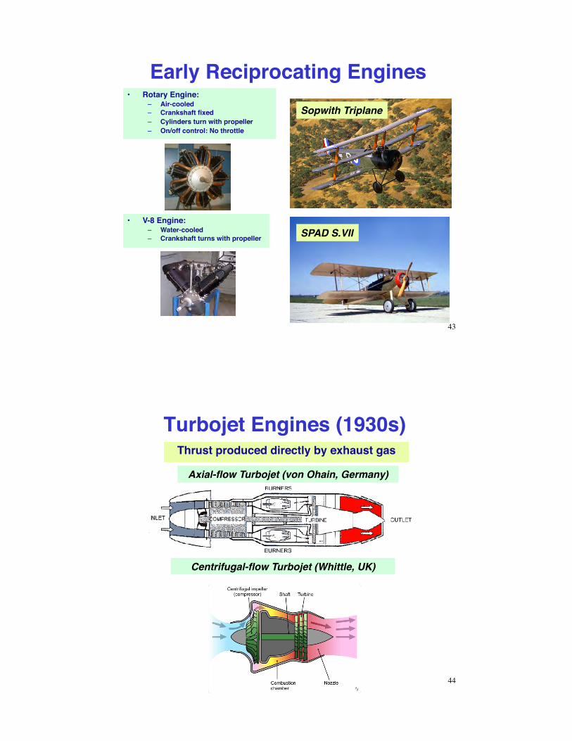
Early Reciprocating Engines•! Rotary Engine:
–! Air-cooled–! Crankshaft fixed–! Cylinders turn with propeller–! On/off control: No throttle
Sopwith Triplane
SPAD S.VII•! V-8 Engine:
–! Water-cooled–! Crankshaft turns with propeller
43
Thrust produced directly by exhaust gas
Axial-flow Turbojet (von Ohain, Germany)
Centrifugal-flow Turbojet (Whittle, UK)
Turbojet Engines (1930s)
44

Birth of the Jet Airplane
Bell P-59A (1942)
Gloster Meteor (1943)
Messerschitt Me 262 (1942)
Heinkel He. 178 (1939)
Gloster E/28/39 (1941)
45
Turbojet + Afterburner (1950s)
•! Fuel added to exhaust•! Additional air may be introduced
•! Dual rotation rates, N1 and N2, typical
46

Fighter Aircraft and EnginesLockheed P-38
Allison V-1710Turbocharged Reciprocating Engine
Convair/GD F-102
P&W J57Axial-Flow Turbojet Engine
MD F/A-18
GE F404Afterburning Turbofan Engine
47
Turboprop Engines (1940s)Exhaust gas drives propeller to produce thrust
48

Turbofan Engine (1960s)
•! Dual or triple rotation rates
49
High Bypass Ratio Turbofan
Propfan Engine
Aft-fan Engine
50
Geared Turbofan Engine

Jet Engine Nacelles
51
Ramjet and ScramjetRamjet (1940s) Scramjet (1950s)
Talos
X-43Hyper-X
X-51 Waverider
52

Isp =Thrust!m go
" Specific Impulse, Units = m/sm/s2 = sec
!m ! Mass flow rate of on -board propellantgo ! Gravitational acceleration at earth's surface
Thrust and Specific Impulse
53
Thrust and Thrust Coefficient
Thrust ! CT12"V 2S
•! Non-dimensional thrust coefficient, CT–! CT is a function of power/throttle
setting, fuel flow rate, blade angle, Mach number, ...
•! Reference area, S, may be aircraft wing area, propeller disk area, or jet exhaust area
54

Sensitivity of Thrust to Airspeed
Nominal Thrust = TN ! CTN
12"VN
2S
.( )N = Nominal or reference( ) valueTurbojet thrust is independent of airspeed
over wide range
55
PowerAssuming thrust is aligned with airspeed vector
Power = P = Thrust !Velocity " CT12#V 3S
Propeller–driven power is independent of airspeed over a wide range
(reciprocating or turbine engine, with constant RPM or variable-pitch prop)
56

Next Time:!Low-Speed Aerodynamics !
Reading:!Flight Dynamics !
Aerodynamic Coefficients, 65-84!
57
SSuupppplleemmeennttaarryy MMaatteerriiaall
58

Reciprocating Engines•! Rotary
•! In-Line
•! V-12 •! Opposed
•! Radial
59
Turbo-compound Reciprocating Engine
•! Exhaust gas drives the turbo-compressor•! Napier Nomad II shown (1949)
60
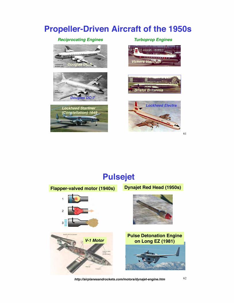
Propeller-Driven Aircraft of the 1950s
Douglas DC-6
Douglas DC-7
Lockheed Starliner (Constellation) 1649
Vickers Viscount
Bristol Britannia
Lockheed Electra
Reciprocating Engines Turboprop Engines
61
PulsejetFlapper-valved motor (1940s) Dynajet Red Head (1950s)
V-1 MotorPulse Detonation Engine
on Long EZ (1981)
http://airplanesandrockets.com/motors/dynajet-engine.htm 62

Jet Transports of the 2000sAirbus A380 Boeing 787
Embraer 195 Boeing 747-8F
63
SR-71: P&W J58 Variable-Cycle
Engine (Late 1950s)
Hybrid Turbojet/Ramjet
64


![Modeling of aerodynamic disturbances for proximity flight ...hiperlab.berkeley.edu/wp-content/uploads/2019/05/... · propeller plane given by momentum theory [14], T is the thrust](https://img.pdfslide.net/doc/110x75/5ebd5c5f6bd13f62360df53b/modeling-of-aerodynamic-disturbances-for-proximity-iight-propeller-plane-given.jpg)