Embed Size (px)
Citation preview
SOCIETA’ NAZIONALE PER L’ASSISTENZA AL VOLO
ENAV S.p.A.
Area Tecnica – Centro Simulazione e Sperimentazione
Point Merge System
Results of ENAV Prototyping Sessions
Ref. : Version : 2.0 Date : 15.09.2008 State : Released Issued Classification : Public

Point Merge System
Results of ENAV Prototyping Sessions
Page 1 State: Released Issue Edition 2.0
DOCUMENT OVERVIEW
TITLE
Point Merge System Results of the Prototyping Sessions
Ref: Edition: 2.0 State: Released Issue Date: 15.09.2008 Classification: Pubblic
Abstract
This document contains the results of the first phase of the ENAV Point Merge System (PMS) project, aimed to assess the domain suitability and controllers’ initial acceptability of applying the PMS concept in Rome Terminal Area (TMA). It presents the results of four prototyping sessions held at Rome Area Control Centre (ACC) in March, April, May and June 2008. During these prototyping sessions the PMS concept has been introduced in Rome TMA for the management of traffic to Fiumicino airport (LIRF), with runways configurations 16R/L and 34L/R and in both full runways configurations and single runway operations. The introduction of the PMS concept did not affect the traffic to Ciampino airport (LIRA) – also included in Rome TMA – that continued to be managed in conventional way. All the studies produced positive results on the user acceptability and domain suitability of introducing the point merge method in Rome TMA. They also confirmed the validity of the incremental and iterative validation approach adopted. A large set of recommendations has been produced that are expected to reveal useful in both the preparation and conduct of the following real time simulation, as well as for the application of the method in operation. Lesson learnt in the project are included in the conclusions.
Contact Point Phone Number E-mail Unit
Roberto Ghidini +39 06 81 66 357 [email protected] ENAV HQ Vincenzo Melgiovanni +39 06 81 66 344 [email protected] CNS/ATM EC
Paola Lanzi +39 06 45 44 37 73 [email protected] DeepBlue
ELECTRONIC VERSION Path: System Software Dimension
Windows-2000 Microsoft Word 2,47MB STATE OF THE DOCUMENT
State Classification Accessible via Working Draft Public Document Intranet Draft Internal Document Extranet Proposed Issue Restricted Document Internet Released Issue
Point Merge System
Results of ENAV Prototyping Sessions
Page 2 State: Released Issue Edition 2.0
AUTHORS AND REVIEW PROCESS
ORGANISATION AUTHORS REVISIONS
Deep Blue srl Paola Lanzi
ENAV CNS/ATM Experimental Centre Vincenzo Melgiovanni
ENAV Rome ACC Francesco Minniti
ENAV HQ
Eurocontrol ERC

Point Merge System
Results of ENAV Prototyping Sessions
Page 3 State: Released Issue Edition 2.0
DOCUMENT APPROVAL
Organisation NAME Role Date Signature
ENAV CNS/ATM Experimental Centre Giancarlo Ferrara Director 15.09.2008

Point Merge System
Results of ENAV Prototyping Sessions
Page 4 State: Released Issue Edition 2.0
DOCUMENT CHANGES RECORD
VERSION DATE REASON FOR CHANGES PAGES/SESSIONS
1.0 29.08.2008 Internal Review All
2.0 15.09.2008
Point Merge System
Results of ENAV Prototyping Sessions
Page 5 State: Released Issue Edition 2.0
Acronyms and Abbreviations ACC Area Control Centre AMAN Arrival Manager CDA Continuous Descend Approach CRIA Critical Interaction Analysis ENAV Ente Nazionale Assistenza al Volo E-TMA Extended Terminal Manoeuvre Area FIFO First In First Out FIR Flight Information Region HF Human Factors HMI Human Machine Interface LIRA Ciampino Airport LIRF Fiumicino Airport LIRN Napoli Airport LIRP Pisa Airport LIRQ Firenze Airport LIRZ Perugia Airport LVP Low Visibility Approach MSP Multi Sector Planning NTZ No Transgression Zone PMS Point Merge System PRNAV Precision Area Navigation RNAV Area Navigation RNP APCH Required Navigation Performance Approach RWY Runway SID Standard Instrument Departure SM Sequence Manager SME Subject Matter Expert STAR Standard Arrival STCA Short Term Conflict Alert TLX Task Load Index TMA Terminal Area TWR Tower WTC Wake Turbulence Category
Point Merge System
Results of ENAV Prototyping Sessions
Page 6 State: Released Issue Edition 2.0
TABLE OF CONTENTS DOCUMENT OVERVIEW........................................................................................... 1
AUTHORS AND REVIEW PROCESS........................................................................ 2
DOCUMENT APPROVAL .......................................................................................... 3
DOCUMENT CHANGES RECORD............................................................................ 4
Acronyms and Abbreviations .................................................................................. 5
Chapter 1 Introduction ............................................................................................. 8 1.1 The Project ............................................................................................................................... 9 1.2 The Operational Concept ....................................................................................................... 11 1.3 The Operational Scenario ...................................................................................................... 13 1.3.1 Runways 16L/R in use at LIRF .............................................................................................. 13 1.3.2 Runways 34L/R in use at LIRF .............................................................................................. 15 1.4 Roles and Working Methods .................................................................................................. 18 1.5 The Simulation Room Layout................................................................................................. 21 1.6 Tools Available ....................................................................................................................... 23
Chapter 2 Evaluation Plan...................................................................................... 24 2.1 Objectives of the Prototyping Sessions.................................................................................. 24 2.2 Hypotheses ............................................................................................................................ 25 2.3 Validation Methodology.......................................................................................................... 25 2.4 Validation Techniques............................................................................................................ 26 2.5 Scenarios ............................................................................................................................... 27 2.6 Exercises................................................................................................................................ 29 2.7 Agenda ................................................................................................................................... 30
Chapter 3 Results of the Prototyping Sessions................................................... 32 3.1 Introduction to the Results ..................................................................................................... 33 3.2 Application of the Point Merge System Method ..................................................................... 34
3.2.1 Use of PMS in case of high traffic load .......................................................................... 35
3.2.2 Use of PMS in case of low traffic load................................................................................ 43
3.2.3 Transition from conventional method to PMS and vice versa ........................................ 47
3.2.4 Use of PMS in case of go around................................................................................... 49
3.2.5 Use of PMS in case of spacing increase........................................................................ 51
3.2.6 Use of PMS in case of runway change .......................................................................... 55
Point Merge System
Results of ENAV Prototyping Sessions
Page 7 State: Released Issue Edition 2.0
3.2.7 Use of the PMS method in case of radio failure..............................................................59
3.2.8 Use of PMS in case of bad weather and mixed equipped traffic ....................................60
3.2.9 Flexible use of the PMS method .....................................................................................63
3.3 Appropriateness of roles and working methods......................................................................67 3.4 Impact on controllers’ workload ..............................................................................................76 3.5 Appropriateness of the simulation room layout.......................................................................80 3.6 Appropriateness of Human Machine Interaction.....................................................................84
3.6.1 Defects of missing information ........................................................................................84
3.6.2 Limits of display settings .................................................................................................86
Chapter 4 Conclusions and Lesson Learnt...........................................................89
Point Merge System
Results of ENAV Prototyping Sessions
Page 8 State: Released Issue Edition 2.0
Chapter 1 Introduction
This document contains the results of the first phase of the ENAV Point Merge System
(PMS) project, aimed to assess the domain suitability and controllers’ initial
acceptability of applying the PMS concept in Rome Terminal Area (TMA).
It presents the results of four prototyping sessions held at Rome Area Control Centre
(ACC) in March, April, May and June 2008. During these prototyping sessions the
PMS concept has been introduced in Rome TMA for the management of traffic to
Fiumicino airport (LIRF), with runways configurations 16R/L and 34L/R and in both full
runways configurations and single runway operations. The introduction of the PMS
concept did not affect the traffic to Ciampino airport (LIRA) – also included in Rome
TMA – that continued to be managed in conventional way.
The report makes up of 4 sections, presenting respectively:
• the introduction to the project and to the prototyping sessions (chapter 1)
• the evaluation plan applied during the prototyping sessions (chapter 2)
• the results of the prototyping sessions (chapter 3)
• conclusions and way forward (chapter 4)
Point Merge System
Results of ENAV Prototyping Sessions
Page 9 State: Released Issue Edition 2.0
1.1 The Project
The ENAV PMS Project aims to evaluate the domain suitability and user acceptability
of introducing the PMS concept in Rome TMA, for the management of traffic to LIRF.
The project is managed by ENAV Headquarter, with extensive cooperation of Rome
ACC and ENAV CNS/ATM Experimental Centre. Support is provided by Eurocontrol
Experimental Centre and Headquarter. Deep Blue is responsible for Human Factors
assessment.
The project makes up of two phases, consequential and strictly interdependent:
• Phase 1 – Small Scale Prototyping Sessions at Rome ACC
• Phase 2 – Large Scale Real-Time Simulation at ENAV CNS/ATM Experimental
Centre
Phase 1 – Prototyping Sessions
The first phase – to which this report refers – focuses on the PMS introduction in the
arrival sectors of Rome TMA. Possible effects on Extended TMA (E-TMA) sectors
and/or on cooperation between E-TMA and TMA sectors are out of the scope of this
first phase and will be investigated in Phase 2.
The first phase has been carried out at Rome ACC. It developed in four small scale
prototyping sessions, in which the concept has been tested in different operational
scenarios depending on the runway configurations in use in both LIRF and LIRA.
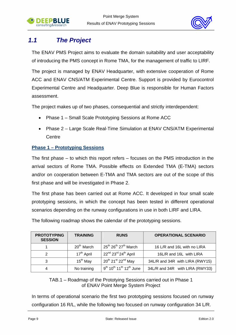
The following roadmap shows the calendar of the prototyping sessions.
PROTOTYPING
SESSION TRAINING RUNS OPERATIONAL SCENARIO
1 20th March 25th 26th 27th March 16 L/R and 16L with no LIRA
2 17th April 22nd 23rd 24th April 16L/R and 16L with LIRA
3 15th May 20th 21st 22nd May 34L/R and 34R with LIRA (RWY15)
4 No training 9th 10th 11th 12th June 34L/R and 34R with LIRA (RWY33)
TAB.1 – Roadmap of the Prototying Sessions carried out in Phase 1 of ENAV Point Merge System Project
In terms of operational scenario the first two prototyping sessions focused on runway
configuration 16 R/L, while the following two focused on runway configuration 34 L/R.
Point Merge System
Results of ENAV Prototyping Sessions
Page 10 State: Released Issue Edition 2.0
An iterative and incremental validation approach has been applied, which had the
twofold purpose to gradually introduce the new concept to the controllers and profiting
by the results of the previous session to prepare the following one.
Following this approach the first prototyping session was based on a simplified
operational scenario marked by lack of traffic destination LIRA, application of
Continuous Descend Approach (CDA) within the triangles despite radar minima
constraints and lack of departures from both LIRA and LIRF. The use of a simplified
operational scenario was intended to allow the controllers involved in the prototyping
session to purely focus on the operational concept under investigation. A more
realistic and complete operational scenario has been then simulated in the following
sessions, in which traffic to LIRA has been added to the traffic samples and radar
minima constraints within the triangles have been taken into account.
Departures have not been simulated in this phase of the project due to possible
interferences between the triangles and the current Standard Instrument Departures
(SIDs).
Phase 2 – Real Time Simulation
The second phase of the project enlarges the scope of the investigation and considers
the possible impact of PMS not only on Rome TMA sectors, but also on E-TMA
sectors.
During this phase a large scale real-time simulation will be arranged and carried out at
ENAV CNS/ATM Experimental Centre. The purpose of the simulation is to assess
domain suitability and user acceptability of the PMS concept in a more complete
operational scenario than the one used in phase 1. The operational scenario taken
into consideration includes both TMA and E-TMA sectors. The traffic samples contain
traffic to and from both LIRF and LIRA, as well as to and from some other minor
airports situated in the Rome Flight Information Region (FIR) such as Napoli (LIRN),
Pisa (LIRP), Firenze (LIRQ), Perugia (LIRZ). Also in this case PMS will be applied
only to the traffic destination LIRF, while the traffic to the other airports will be
managed in the conventional way.
In addition to PMS, Arrival Manager (AMAN) will be also introduced in the second
phase of the project. Although AMAN is not mandatory for the use of PMS, it will be

Point Merge System
Results of ENAV Prototyping Sessions
Page 11 State: Released Issue Edition 2.0
proposed as a support for the pre-sequencing managed by E-TMA sectors controllers.
The evaluation of the possible interoperability between AMAN and PMS is one of the
main objectives of the second phase of the project.
1.2 The Operational Concept
The PMS operational concept applied in the project has been borrowed from the
original one developed at the Eurocontrol Research Centre and represented in Fig.1.
Fig. 1. Point merge system – example with two inbound flows
According to this operational concept, PMS is a new ATC technique aimed to facilitate
the merging of traffic from a number of Area Navigation (RNAV) arrival routes.
The technique is based upon aircraft flying a quasi-arc, up to 30NM long, with a radius
of 20+NM from the designated merge point. Each arc has a published altitude that the
aircraft must have reached before establishing on the arc and a predefined speed to
fly it. A pre-requisite for the effective application of the concept is that upstream
sectors controllers hand the traffic over to the arrival sectors already steady and at
constant and predefined speed.
Merge point
Sequencing legs
Envelope of possible paths
Arrival flow
Arrival flow
Integrated sequence
(at iso-distance fromthe merge point)
Point Merge System
Results of ENAV Prototyping Sessions
Page 12 State: Released Issue Edition 2.0
In general the arc nearest to the merge point has the highest altitude while the other
has the lowest altitude in order to make the descent of the traffic leaving the external
sequencing leg free from traffic flying the internal one.
Each point of the sequencing leg is iso-distance from the merge point.
The controller clears the aircraft off the arc direct to the merge point when separation
from the preceding aircraft is assured. After appreciating the aircraft turn to the merge
point, and providing that the aircraft is clear of all the other traffic, the controller clears
it to descend. CDA is applied in this phase, if the orographic characteristics of the area
allow it. In alternative step descent is foreseen.
If the aircraft reaches the end of the arc without receiving a “direct to merge point”
clearance, it turns automatically towards the merge point maintaining the current
altitude. Final waypoint of each arc is recommended to be a “fly-over”, thereby
providing the controller with an unambiguous turning point for Lost Communications
aircraft while ensuring the maximum time to manage the traffic.
Unless the final approach is RNAV (Required Navigation Performance Approach -
RNP APCH) the missed approach is conventional, with radar vectoring to place the
aircraft back into the arrival stream.
Holding points are established prior to the arcs to cater for traffic peaks, missed
Approaches, low visibility approach (LVP) operations and a temporary runway closure.
For the application of the PMS concept in Rome TMA, two triangles have been
introduced in both operational scenarios RWY 34L/R and 16L/R.
One triangle is on the East, the other on the West. Each triangle is associated to one
point merge and to one runway that it is intended to feed.
The basic principle to link triangles, point merges and runways is to make traffic from
the East landing on RWY 16L/34R and traffic from the West landing on RWY16R/34L.
Nevertheless considering the different landing rate of the two runways and the bearing
of the traffic flows, runway change is allowed in specific situations, such as before
entering in the triangles or flying inside a triangle to land on the other runway. The
runway change has to be planned/coordinated by SM LIRF in order to profit by the
capacity of both runways, avoid delays and/or satisfy specific pilots’ requests.
In case of single runway operations both triangles feed the runway in use and the
Point Merge System
Results of ENAV Prototyping Sessions
Page 13 State: Released Issue Edition 2.0
integration of the traffic flows is based on the “first in, first out” (FIFO) principle.
1.3 The Operational Scenario
Different operational scenarios have been simulated during the prototyping sessions.
As already stated in par. 1.1:
• the first and second prototyping sessions were based on runway configuration
16L/R. The first one adopted a simplified operational scenario marked by no
consideration of radar minima constraints within the triangles and traffic
samples made up of only traffic inbound to LIRF. In the second one traffic to
LIRA (RWY 33) and radar minima constraints have been added.
• the third and forth prototyping sessions were based on runway configuration
34R/L, with RWY 15 and 33 respectively in use in LIRA. In both cases radar
minima constraints have been taken into consideration and traffic to LIRA was
included in the traffic samples.
Traffic to LIRA, when present, was not managed with the PMS method, but in the
conventional way.
For specific internal ENAV objectives, parallel independent approaches to LIRF were
simulated during the prototyping sessions, even if not in operations yet.
1.3.1 Runways 16L/R in use at LIRF
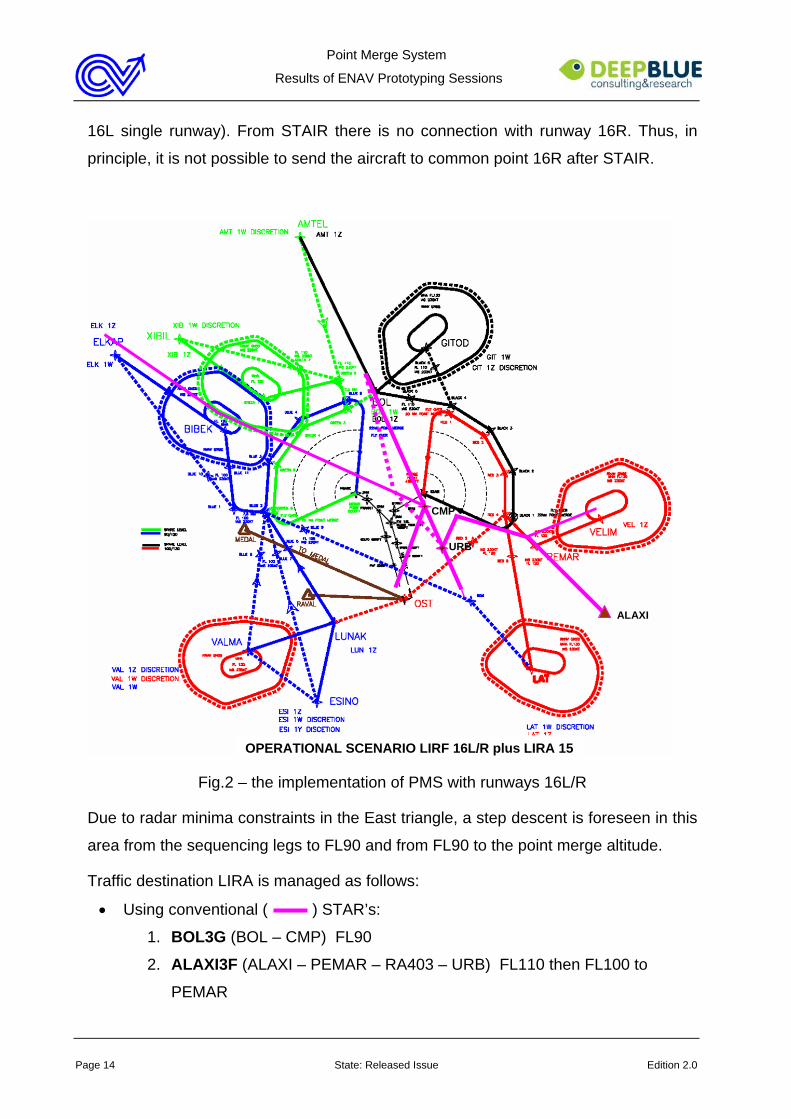
The following Fig.2 represents the way the PMS concept has been applied in Rome
TMA when runways 16 L/R are in use in LIRF and runway 15 is in use in LIRA. This
operational scenario has been applied in the first two prototyping session, with the
difference that in the first one the inbound traffic to LIRA (whose trajectory is depicted
in magenta) was not present in the traffic samples.
The West triangle is associated to merge point FRANK (5.000 feet) and to runway
16R, while the East one is associated to STAIR (4.000 feet) and to runway 16L.
According to the operational concept applied, runway change can be performed using
the ATC discretion routes (dot lines) or clearing the aircraft from FRANK to common
point 16L, in case of traffic from the West landing on 16L (in both scenarios 16L/R and
Point Merge System
Results of ENAV Prototyping Sessions
Page 14 State: Released Issue Edition 2.0
16L single runway). From STAIR there is no connection with runway 16R. Thus, in
principle, it is not possible to send the aircraft to common point 16R after STAIR.
Fig.2 – the implementation of PMS with runways 16L/R
Due to radar minima constraints in the East triangle, a step descent is foreseen in this
area from the sequencing legs to FL90 and from FL90 to the point merge altitude.
Traffic destination LIRA is managed as follows:
• Using conventional ( ) STAR’s:
1. BOL3G (BOL – CMP) FL90
2. ALAXI3F (ALAXI – PEMAR – RA403 – URB) FL110 then FL100 to
PEMAR
ALAXI
URB
CMP
OPERATIONAL SCENARIO LIRF 16L/R plus LIRA 15
Point Merge System
Results of ENAV Prototyping Sessions
Page 15 State: Released Issue Edition 2.0
3. VELIM3F (VELIM – PEMAR – RA403 – URB) FL120 then FL100 to
PEMAR
4. OST3G (OST – CMP) alt 6000ft
5. ELKAP3F (ELKAP – BIBEK – CMP) FL130
• Using Radar Vectors ( ):
Suggested Heading from BOL is 165° until crossing west abeam of STAIR, then
direct URB for ILS15.
1.3.2 Runways 34L/R in use at LIRF
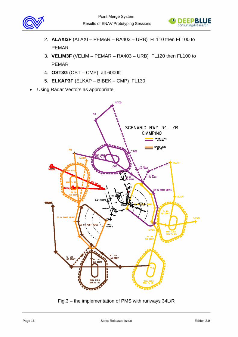
The following Fig.3 represents the way the PMS concept has been applied in Rome
TMA when runways 34 L/R are in use in LIRF. A wind of 28kts direction 330 below
FL110 has been simulated during the prototyping sessions in order to justify the use of
this operational scenario.
The West triangle is associated to merge point VANIA (3.000 feet) and to runway 34L,
while the East one is associated to SHARA (4.000 or 5.000 feet depending on the
runway in use in LIRA) and to runway 34R.
According to the operational concept applied, runway change can be performed using
the ATC discretion routes (dot lines) or clearing the aircraft from VANIA to common
point 34R, in case of traffic from the West landing on RWY 34R (in both scenarios
34L/R and 34R single runway). From SHARA there is no connection with runway 34L.
Thus, in principle, it is not possible to send the aircraft to common point 34L after
SHARA.
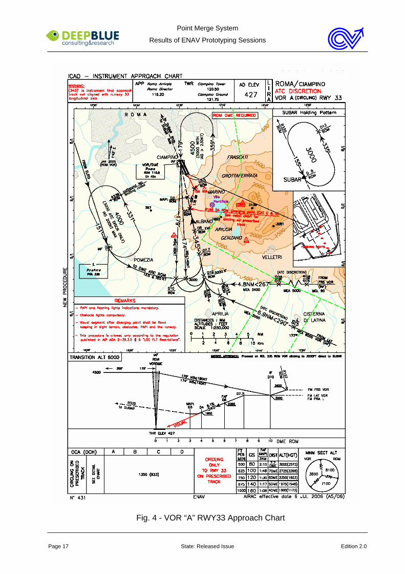
Traffic destination LIRA is managed in a different way depending on the runway in
use. With runway 33 VOR “A” procedures has to be applied. It is depicted in the
following approach chart in Fig.4. The only change with respect to the original
procedure is the starting altitude, which is 4000ft instead of 4500ft, to remain clear of
the final eastern paths to the merge point (SHARA).
With runway 15 in LIRA instead the traffic to LIRA can be managed as follows:
• Using conventional STAR’s:
1. BOL3G (BOL – CMP) FL90
Point Merge System
Results of ENAV Prototyping Sessions
Page 16 State: Released Issue Edition 2.0
2. ALAXI3F (ALAXI – PEMAR – RA403 – URB) FL110 then FL100 to
PEMAR
3. VELIM3F (VELIM – PEMAR – RA403 – URB) FL120 then FL100 to
PEMAR
4. OST3G (OST – CMP) alt 6000ft
5. ELKAP3F (ELKAP – BIBEK – CMP) FL130
• Using Radar Vectors as appropriate.
Fig.3 – the implementation of PMS with runways 34L/R
Point Merge System
Results of ENAV Prototyping Sessions
Page 17 State: Released Issue Edition 2.0
Fig. 4 - VOR “A” RWY33 Approach Chart
Point Merge System
Results of ENAV Prototyping Sessions
Page 18 State: Released Issue Edition 2.0
1.4 Roles and Working Methods
The adoption of the operational concept described in par.1.2 and 1.3 required some
changes in the working methods applied in Rome TMA for the management of arrival
traffic to LIRF.
These changes, concerning both E-TMA and TMA Sectors, were quite limited (see
details below), as roles and working methods have been designed in order to be as
much coherent as possible with those currently in use in Rome ACC.
This choice of continuity between the two operational realities had the twofold purpose
to allow the controllers to:
• be deeply involved in the definition of the best way to apply the new technique
• perceive the new technique as an evolution of the way the traffic is currently
managed, instead of a radical revolution, thus increasing the acceptability of
the technique itself.
E-TMA sector controllers
E-TMA sector controllers (managed as a feed sector during the prototyping sessions)
conform to standard roles in use in Rome ACC. The only modifications introduced in
their working methods concern the requirements to:
• pre-sequence the arrival traffic at a minimum distance of 7NM
• provide TMA sectors with arrival traffic at a pre-defined flight level and speed
reported on the maps (par.1.3)
• reach both the conditions above at least 10NM prior the aircraft enters the
sequencing leg
Traffic to LIRA has to be spaced as in normal operations (at least 7NM).
These changes in the working methods of E-TMA sector controllers are considered a
pre-requisite for the effective application of the operational concept at concern.
SM LIRF
Being responsible for the arrival traffic management in the overall simulated airspace,
SM LIRF has to monitor a wide working area.
Point Merge System
Results of ENAV Prototyping Sessions
Page 19 State: Released Issue Edition 2.0
His main task is to balance east and west flows of traffic in respect of the defined
constraints (e.g. landing rate, WTC, slot insertion,…), and handle potential
unexpected situation.
SM LIRF optimises the sequence giving instructions to E-TMA sector (NW, NE, US,
DP), taking into account any other possible re-routing which may help in balancing the
traffic and reducing the overall delay.
In case of single RWY operation, SM LIRF coordinates the gap where to insert the
aircraft with SM LIRA.
In addition, in case of full runways configuration, he informs SM LIRA, TNW and ARW
of the traffic flying the west envelope expected to land on the other runway. He also
informs SM LIRA of traffic landing in LIRA coming from West. For this traffic
coordination with SM LIRA may also be required in order to defined the most suitable
route to follow.
SM LIRA
Being responsible for the arrival traffic management associated to LIRA, SM LIRA
determines the strategy to keep the arrival flow to LIRA apart and independent from
the envelope of paths which are LIRF dedicated and coordinates all the inbound
warning and releases with LIRA TWR.
Moreover he:
• informs ARE of the traffic flying the west envelope expected to land on east
runway and all the traffic landing in LIRA coming from the other sector (west).
• coordinates any potential runway change which may occur after the merge
points with LIRF TWR giving sudden warning to SM LIRF.
• informs SM LIRF in case of unpredicted runway change
• in case of single RWY operation mode, informs both AR of the traffic flying
from the west envelope.
TNW Sector (freq. 125.500)
TNW Controller issues the “Turn left/right direct to merge point (FRANK/VANIA) and
descend to (5000 or 3000 ft)” instructions to the proper aircraft using the range ring
Point Merge System
Results of ENAV Prototyping Sessions
Page 20 State: Released Issue Edition 2.0
arcs to assess the appropriate spacing from the preceding aircraft.
After appreciating the turn he hands the traffic over to ARW sector.
A different defined spacing is applied according to the landing rate requested.
In RWY 16L/R operational scenario TNW has to deal in a particular way with the traffic
destination LIRA coming from the West. The traffic to LIRA flying ELKAP3F has to be
cleared not below FL130 until crossing the West triangle, then it can be cleared to
further descend to FL 100 as appropriate. Leaving the West triangle TNW hands this
traffic over to ARE.
TNE Sector (freq. 127.950)
TNE Controller issues the “Turn left/right direct to merge point (STAIR/SHARA) and
descend to (4000 or 5000 ft)” instructions to the proper aircraft using the range ring
arcs to assess the appropriate spacing from the preceding aircraft.
After appreciating the turn the traffic is sent in contact with ARE sector.
A different defined spacing is applied according to the landing rate requested.
In RWY 16L/R operational scenario TNE has to deal with the step descend that is
necessary in a part of the triangle. In this case has clear the aircraft to descend to
FL90 and contact ARE, instead of clearing it to descend directly to STAIR.
In RWY 34L/R operational scenario TNE has to deal in a particular way with the traffic
destination LIRA coming from the East. The traffic to LIRA flying ALXI/VELIM3F has to
be cleared not below FL130 until crossing the East triangle, then it can be cleared to
further descend to FL 100 as appropriate. Leaving the East triangle TNE hands the
traffic over to ARE.
ARW (freq. 119.200)
ARW Controller optimises 16R/34L sequence by using the PMS technique as
appropriate. Upon receiving the traffic in contact leaving the sequencing legs, he
monitors the aircraft descent issued by TNW controller and adjusts the speed if
necessary to optimise the required spacing.
He also provides vertical separation between aircraft in independent parallel
approaches until they are within the NTZ, and established on the respective ILS
Point Merge System
Results of ENAV Prototyping Sessions
Page 21 State: Released Issue Edition 2.0
localiser course.
When traffic landing on 16L/34R is managed by ARW:
• vertical separation is applied between traffic landing on the two runways
• frequency change is provided as soon as possible after the point merge and/or
when safely appropriate.
ARE (freq. 131.250)
ARE Controller optimises 16L/34R sequence by using the PMS technique as
appropriate. Upon receiving the traffic in contact leaving the sequencing legs, he
monitors the aircraft descent issued by TNE controller and adjusts the speed if
necessary to optimise the required spacing.
He also provides vertical separation between aircraft in independent parallel
approaches until they are within the NTZ, and established on the respective ILS
localiser course.
In both single runway and full runway configurations ARE is responsible for building
the sequence to LIRA using STARs and radar technique as appropriate according to
the requested landing rate. Traffic destination LIRA has been previously pre-arranged
by SM LRA and pre-sequenced by TNE when sent in contact to ARE.
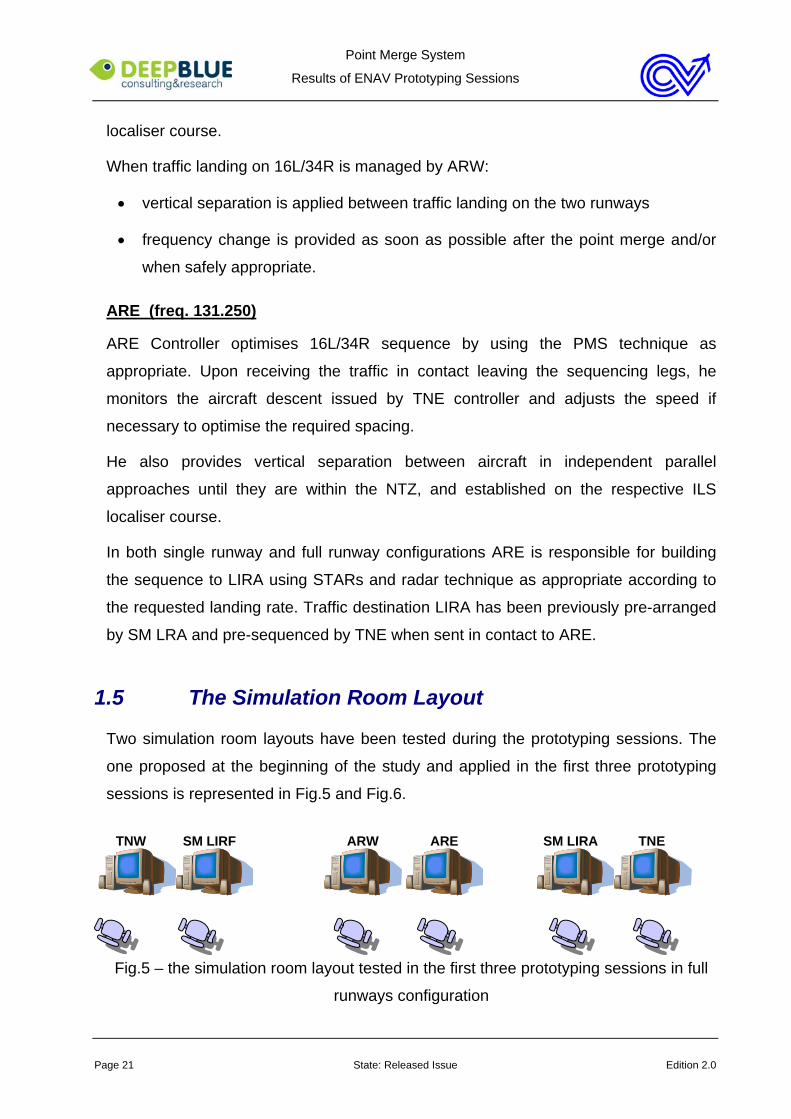
1.5 The Simulation Room Layout
Two simulation room layouts have been tested during the prototyping sessions. The
one proposed at the beginning of the study and applied in the first three prototyping
sessions is represented in Fig.5 and Fig.6.
TNW SM LIRF ARW ARE SM LIRA TNE
Fig.5 – the simulation room layout tested in the first three prototyping sessions in full
runways configuration
Point Merge System
Results of ENAV Prototyping Sessions
Page 22 State: Released Issue Edition 2.0
The adoption of this simulation room layout has been constrained to be in line with the
real operative room layout, according to which no more than two controller working
positions could be located on each desk. This is the reason why the working positions
are coupled, with gaps between the three couples. Given this constraint, the
controllers working positions have been set out in order to allow:
• ARW and ARE controllers to work closely (a must with parallel independent
approach)
• each SM to stay in between the TN and AR controllers of his area
This simulation room layout requires SM LIRF and SM LIRA to coordinate by phone.
In case of single runway scenario, this operational room layout was slightly different.
As represented in Fig.6 there is one TN controller per each triangle, both SM LIRF
and LIRA and one unique AR sector in which both ARE and ARW collapse.
TNW SM LIRF AR SM LIRA TNE
Fig.6 – the simulation room layout tested in the first three prototyping sessions in
single runway configuration
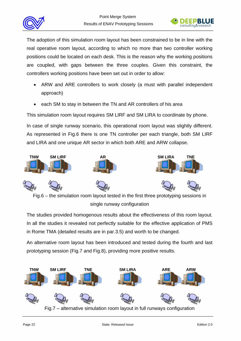
The studies provided homogenous results about the effectiveness of this room layout.
In all the studies it revealed not perfectly suitable for the effective application of PMS
in Rome TMA (detailed results are in par.3.5) and worth to be changed.
An alternative room layout has been introduced and tested during the fourth and last
prototyping session (Fig.7 and Fig.8), providing more positive results.
TNW SM LIRF TNE SM LIRA ARE ARW
Fig.7 – alternative simulation room layout in full runways configuration
Point Merge System
Results of ENAV Prototyping Sessions
Page 23 State: Released Issue Edition 2.0
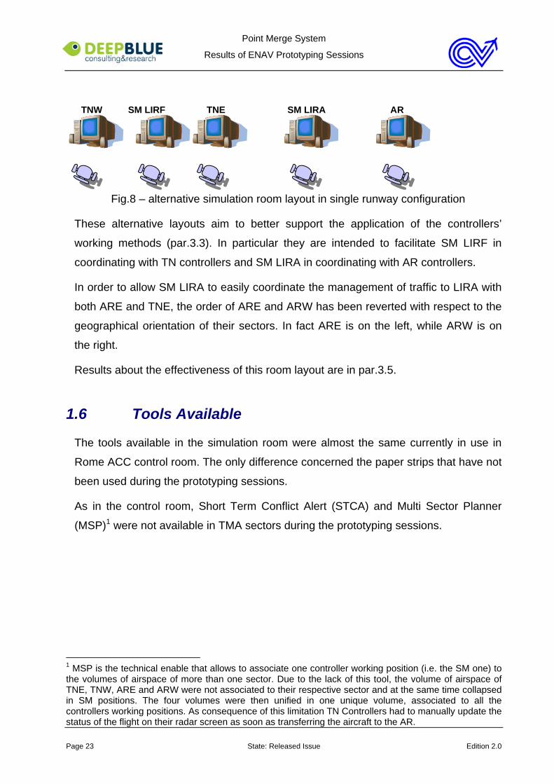
TNW SM LIRF TNE SM LIRA AR
Fig.8 – alternative simulation room layout in single runway configuration
These alternative layouts aim to better support the application of the controllers’
working methods (par.3.3). In particular they are intended to facilitate SM LIRF in
coordinating with TN controllers and SM LIRA in coordinating with AR controllers.
In order to allow SM LIRA to easily coordinate the management of traffic to LIRA with
both ARE and TNE, the order of ARE and ARW has been reverted with respect to the
geographical orientation of their sectors. In fact ARE is on the left, while ARW is on
the right.
Results about the effectiveness of this room layout are in par.3.5.
1.6 Tools Available
The tools available in the simulation room were almost the same currently in use in
Rome ACC control room. The only difference concerned the paper strips that have not
been used during the prototyping sessions.
As in the control room, Short Term Conflict Alert (STCA) and Multi Sector Planner
(MSP)1 were not available in TMA sectors during the prototyping sessions.
1 MSP is the technical enable that allows to associate one controller working position (i.e. the SM one) to the volumes of airspace of more than one sector. Due to the lack of this tool, the volume of airspace of TNE, TNW, ARE and ARW were not associated to their respective sector and at the same time collapsed in SM positions. The four volumes were then unified in one unique volume, associated to all the controllers working positions. As consequence of this limitation TN Controllers had to manually update the status of the flight on their radar screen as soon as transferring the aircraft to the AR.
Point Merge System
Results of ENAV Prototyping Sessions
Page 24 State: Released Issue Edition 2.0
Chapter 2 Evaluation Plan
This chapter presents the evaluation plan applied in the prototyping sessions. The
evaluation plan has been developed on the basis of the project objectives and of the
operational concept described in previous chapter. The same evaluation plan has
been almost applied in all the prototyping sessions in order to foster the comparison of
their results.
2.1 Objectives of the Prototyping Sessions
The objective of the prototyping sessions was to assess the domain suitability and
controllers’ acceptability of the PMS concept implemented in Rome TMA.
The assessment mainly focused on the following Human Factors (HF) issues:
• working methods, procedures, roles and responsibilities
• workload
• working layout
• Human Machine Interaction
Point Merge System
Results of ENAV Prototyping Sessions
Page 25 State: Released Issue Edition 2.0
2.2 Hypotheses
Introducing the PMS technique in Rome TMA the following outcomes were expected
in terms of operability:
• standardisation of the arrival management
• effective use of the runway capacity
• acceptable workload
These hypotheses have been purposely defined in order not to be comparative with
the current operational reality of Roma ACC. The purpose of the phase 1 was to
evaluate users’ acceptability and domain suitability of the application of the new PMS
technique in Rome TMA. The comparison with the current operations was considered
out of the scope of this phase and not adequate at this preliminary stage. The choice
of not performing a comparative study had moreover the purpose to fully profit by the
short duration of each session to apply and test the new technique (par.2.7), without
the need to run baseline exercises as the comparative study would have required.
2.3 Validation Methodology
The CRIA© validation methodology has been applied during the preparation, conduct
and analysis of the prototyping sessions reported.
CRIA© is a HF methodology for the investigation of safety critical systems. The main
goal of CRIA© is to analyse the interactions between the human component of a
system and the other system components: procedures, equipment, other humans,
organisational aspects. Such analysis brings to the identification of strength and
weakness points of the system as a whole, so that mitigation actions can be studied to
reduce the probability of the occurrence and the severity of critical events within the
system.
CRIA© has its theoretical foundation in the distributed cognition theory that claims that
human cognition is not exclusively characterised by the brain activity but is distributed
among the brain and the artefacts employed carrying out the activity. This idea dates
back to the cultural-historical school asserting that all kinds of conscious human
activities are structured by the use of external tools.
Point Merge System
Results of ENAV Prototyping Sessions
Page 26 State: Released Issue Edition 2.0
Following this approach, key features of CRIA© are:
• the recognition of the importance of all mediating artefacts both material (such
as flight deck technologies, checklist, manuals, etc) and immaterial (practices,
operational procedures, competencies, Company guidelines, legislation, etc.)
used by the human being to carry out the activity.
• the recognition of the importance of the cultural and organisational milieu in
which human activities develop.
• the use of structured narrative scenarios to represent the interactions between
human actors and mediating artefacts, by preserving realism of the context.
CRIA© has been successfully used in real time simulations, shadow mode trials and
live flight trials. It has proved to be a flexible and adaptable methodology to evaluate
new concepts and tools, as well as minor changes to the current operational situation.
2.4 Validation Techniques
During the prototyping sessions the CRIA© validation methodology has been applied
in combination with two classes of validation techniques, based respectively on the
observation of the controllers’ work during the runs and on the collection of their
feedback at the end of the runs.
During the runs the observation consisted in:
• human factors observation, focused on the HF issues listed in par.2.1
• Subject Matter Expert (SME) observation, aimed at investigating the impact of
the new PMS application on the controllers’ work and on the effectiveness of
the traffic management
• video-recording of the runs
The post run feedback collection has been instead based on:
• post-exercise questionnaire (based on NASA TLX) for the evaluation of the
workload perceived by each controller during the run
• post-exercise debriefing, involving all the participants in the simulation. The
debriefing was a useful occasion to get the controllers’ feedback and freely
Point Merge System
Results of ENAV Prototyping Sessions
Page 27 State: Released Issue Edition 2.0
discuss about the effectiveness and acceptability of the PMS technique.
Qualitative data have been gathered by means of these techniques. Quantitative data
have not been recorded due to limitations in the simulation platform.
2.5 Scenarios
As mentioned above, the use of narrative scenarios is one of the key aspects of
CRIA©. Scenarios present the advantage to recreate events or aspects of the work
that are relevant for the analysis in a realistic operational environment. They often put
together the information coming from different sources (i.e. field observation,
documents, interviews, story telling, etc.) and from different persons (i.e. controllers,
subject matter experts, human factors analysts, developers, etc.) with the final aim to
analyse the potential impact that a new cognitive artefact (i.e. a procedure, a tool, a
new work organisation, etc.) can have on the safety critical system.
Using scenarios instead of exercises has the advantages to allow the analysis of
specific situations that otherwise may not happen and to control the experimental
setting, knowing in advance the event that is going to happen.
For the preparation of the scenarios used during the prototyping session the following
sources have been used:
• documentation about the arrival management in Rome TMA
• documentation about the PMS operational concept
• interviews with operational experts involved in the project
This investigation brought to the identification of a number of relevant events, that
have been then formulated as scenarios, associated to the exercises and executed
during predefined runs of the prototyping sessions.
Two classes of scenarios have been used:
• basic scenarios, concerning nominal events that can happen quite often
• exceptional scenarios, concerning non nominal events that can happen quite
rarely and reveal critical for the application of the PMS method.
Basic scenarios have been executed, in the same exercise, in all the studies. They

Point Merge System
Results of ENAV Prototyping Sessions
Page 28 State: Released Issue Edition 2.0
have been repeated several times during each prototyping session, in different traffic
conditions and with different traffic loads.
Exceptional scenarios have been introduced from the second prototyping session on.
Two of these exceptional scenarios have been executed during the second and third
prototyping sessions. The others have been tested in the forth prototyping session.
They have been executed once in each of the prototyping sessions interested.
The following table summarises the scenarios executed in the studied.
CLASSES SCENARIOS PROTOTYPING SESSIONS
Scenario 1
In single runway operations LIRF TWR requires a 12NM spacing on runway 16L/34R for inspection
1-2-3-4
Scenario 2
In full runways configuration LIRF TWR requires a 12NM spacing on RWY 16L/34R for inspection
1-2-3-4
Scenario 3
In full runways configuration LIRF TWR requires 8NM spacing on runway 16L/34R due to radar problems
1-2-3-4
Scenario 4
In full runways configuration LIRF TWR requires 8NM spacing on runway 16R/34L due to departures
1-2-3-4
Scenario 5
In full runways configuration one aircraft from South-East asks the controller to land on runway 16R/34L
1-2-3-4
Scenario 6
In full runways configuration one aircraft from North-West asks the controller to land on runway 16L/34R
1-2-3-4
BASIC SCENARIOS WITH NOMINAL EVENTS
Scenario 7
In full runways configuration one aircraft landing on runway 16L/34R does not establish on the localizer
1-2-3-4
Point Merge System
Results of ENAV Prototyping Sessions
Page 29 State: Released Issue Edition 2.0
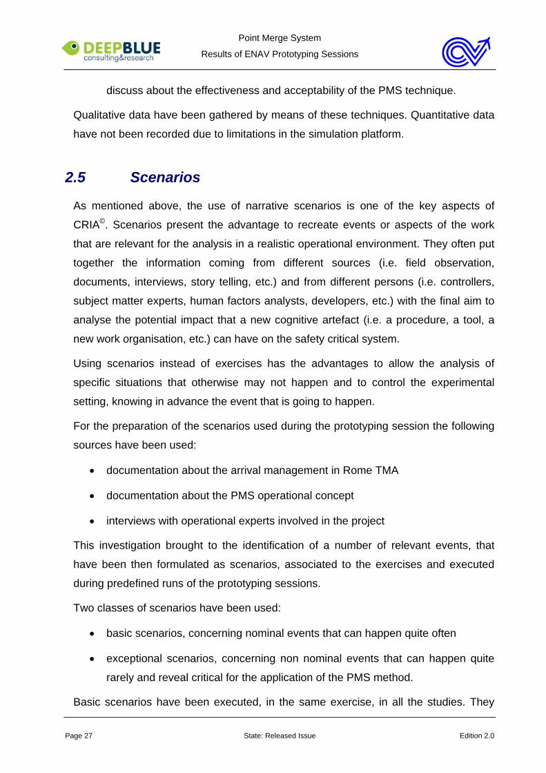
Scenario 8
In full runways configuration radio failure of one aircraft in the East triangle
2-3
Scenario 9
In full runways configuration bad weather affecting the East triangle
2-3
Scenario 10
In full runways configuration transition from radar vectoring procedures to PMS
4
Scenario 11
In full runways configuration E-TMA sectors do not succeed in pre-sequencing the inbound traffic as required for the application of the PMS method
4
Scenario 12
In full runways configuration, closure of runway 34L
4
Scenario 13
In full runways configuration, management of a few traffic not PRNAV equipped
4
EXCEPTIONAL SCENARIOS WITH NON NOMINAL EVENTS
Scenario 14
Sudden transition from PMS to radar vectoring due to DME Off
4
TAB.2 – the Scenarios executed in the prototyping sessions
2.6 Exercises
A set of 9 exercises has been developed for the prototyping sessions using one traffic
sample recorded at Rome ACC as a reference.
The nine exercises were different one from the others and realistic, even if modified
with respect to the original traffic sample in order to have in each exercise a specific
traffic density and often specific traffic conditions suitable for the scenarios execution.
Some Heavy traffic (in realistic percentage) and no Light traffic were included in the
traffic samples. The traffic was intended to be 100% PRNAV equipped, but for the

Point Merge System
Results of ENAV Prototyping Sessions
Page 30 State: Released Issue Edition 2.0
exercise including scenario 13 (par.2.5). This choice was based on the consideration
that at present more than 90% of the traffic interesting Rome TMA is PRNAV
equipped (source Eurocontrol).
Three traffic densities have been implemented in the exercises, on the basis of the
current capacity of LIRF (37 and 54 aircraft/h respectively in single runway and full
runways operations) and LIRA (11 aircraft/h). The three densities were:
• Density 1 (aircraft/h): LIRF 40 + LIRA 8
• Density 2 (aircraft/h): LIRF 50 + LIRA 11
• Density 3 (aircraft/h): LIRF 60 + LIRA 15
Densities 1, 2 and 3 have been tested in full runways configurations, while only
density 1 has been applied in single runway operations. In fact:
• two exercises have been produced to be executed in single runway operations,
both with traffic density 1 (40 aircraft/h)
• 7 exercises have been planned in full runways configuration, among which 2
exercises with density 1 (40 aircraft/h), 3 with density 2 (50 aircraft/h) and 2
with density 3 (60 aircraft/h)
• three exercises out of nine – namely one per each traffic density– have been
planned to be executed without scenarios; in the others one or more scenarios
have been planned to happen.
Each exercise had a 60 minutes duration. In order not to bias the results:
• a seating plan has been produced, defining the controllers’ turn over on the
working positions
• controllers have been instructed to behave in a realistic way.
2.7 Agenda
The prototyping sessions lasted 4 working days each. The first day was generally of
training, but for the fourth and last prototyping session in which the training has not
been executed. A minimum of nine exercises has been executed in each prototyping
session. The agenda of the studies was almost similar, with minor differences due to

Point Merge System
Results of ENAV Prototyping Sessions
Page 31 State: Released Issue Edition 2.0
organisational constraints. The agendas were based on the following principles:
• each day started with a briefing involving the simulation staff and the controllers
participating in the study
• each exercise lasted about one hour and was followed by a post-exercise
questionnaire and a collective debriefing
• three exercises a day were schedule
• the exercises were arranged in order to limit the effects of possible biases such
as learning effects and tiredness
• the controllers rotation on the working positions was regulated by a seating
plan aiming to make them covering all the positions in an homogeneous way

Point Merge System
Results of ENAV Prototyping Sessions
Page 32 State: Released Issue Edition 2.0
Chapter 3 Results of the Prototyping Sessions
This chapter presents the results of the prototyping sessions held at Rome ACC with
the purpose of evaluating the users’ acceptability and domain suitability of applying
the PMS technique in Rome TMA.
As already discussed in previous chapters, the focus of the study was on the effects of
the point merge method on the TMA sectors when runways 16L/R and 34L/R are in
use in LIRF and runways 15 and 33 are in use in LIRA.
The choice of not considering its possible impact on upstream sectors was due to the
incremental approach adopted in the project (par.1.1). According to the project
organisation this first phase (to which this report refers) focuses just on TMA aspects,
while phase 2 enlarges the scope of the analysis and investigates the overall impact
of PMS in both TMA and upstream sectors.
Point Merge System
Results of ENAV Prototyping Sessions
Page 33 State: Released Issue Edition 2.0
3.1 Introduction to the Results
The prototyping sessions produced positive results on the users’ acceptability and
domain suitability of applying the PMS technique in both the simulated operational
scenarios of Rome TMA.
The controllers involved in the studies found the method comfortable, safe, accurate
and easy to learn and to apply. In very short time they became familiar with it and able
to apply it properly and effectively, even under high traffic load and in case of non
nominal events. They considered the new technique suitable to and easy to accept in
Rome TMA arrival sectors. They also tended to perceive it as the evolution of the
current method based on radar vectoring as result of the introduction of the PRNAV
capability, rather than as a radical revolution of the arrival traffic management.
In their opinion the adoption of this method is likely to yield the following advantages:
• standardisation of the controllers performances, thus implying a standard high
quality of the traffic management, less conditioned by personal skills and one’s
own tolerance of traffic density and complexity
• improved teamwork, since the standardisation of the work allows to predict and
anticipate the colleague’s behaviour, expectations and needs
• general reduction of controller cognitive workload in all TMA sectors, since the
standard way of managing the arrival traffic simplifies the work and reduces
the need for problem solving, continuous monitoring, R/T and phone
communication
• general high level of job satisfaction in the controllers, since the less creativity
required to manage the arrival traffic is counterbalanced by evident positive
results in terms of spacing and usage of runway capacity.
They also highlighted some drawbacks of the PMS technique, among which the
following ones are worth to be reported:
• loss of flexibility with respect to the current open loop vectors technique
• conditioned applicability in certain circumstances (i.e. bad weather conditions
impairing the use of both triangles and point merges), that entails the need for
radar vectoring to continue to be applied
Point Merge System
Results of ENAV Prototyping Sessions
Page 34 State: Released Issue Edition 2.0
• concurrent application of radar vectoring and PMS method in case of traffic not
100% PRNAV equipped
• possible impact on the controllers workload in E-TMA sectors
The controllers involved in the studies tended to accept these drawbacks as tolerable
side effects of the PMS technique. They were conscious of these limitations, but did
not consider them as limitative as to impair the acceptability of the technique itself
and/or its effectiveness. The management of non nominal events (such as bad
weather, mixed equipped traffic samples and transition from PMS to radar vectoring
and vice versa) confirmed these results.
The following paragraphs present the detailed results of the prototyping session.
These results have been structured in five paragraphs, discussing respectively about:
• the application of the PMS method during the study
• the appropriateness of the roles and working methods applied
• the impact of the PMS technique on controllers’ workload
• the appropriateness of the working layout adopted
• aspects related to Human Machine Interaction
Recommendations and way forward for the next stage of the project are included.
3.2 Application of the Point Merge System Method
The controllers involved in the studies appreciated the PMS method proposed in the
project, considering it as an effective means to reduce the complexity of the arrival
traffic management in Rome TMA by taking advantage of aircraft PRNAV capabilities.
The provision of triangles, sequencing legs and distance ring, together with the
associated rules and working methods, was perceived as a powerful -and at the same
time simple- means to externalise the controllers’ knowledge, distribute it in the
operational environment, structure the controllers’ work in a standard way and reduce
their cognitive workload.
The results of the prototyping sessions are extremely homogenous. They concern the
use of the method in a variety of cases, among which:
Point Merge System
Results of ENAV Prototyping Sessions
Page 35 State: Released Issue Edition 2.0
• high traffic load
• low traffic load
• go around procedure
• runway change
• spacing increase
• radio failure
• bad weather
• runway closure
• transition from PMS to conventional method and vice versa
• inadequate pre-sequencing
• mixed equipped traffic
They are also coherent in highlighting the possibility of a flexible use of the method.
3.2.1 Use of PMS in case of high traffic load
With high traffic load the studies have highlighted that the amount of traffic in the
triangle is a key element for the effective use of the PMS method. In case of high
traffic load, in fact, both too busy and not busy enough triangles may lead to
disappointing results in terms of controllers’ workload and effective use of the runway
capacity.
The conclusion to which the controllers finally came out during the studies was that for
the successful application of the method the triangles should be completely and
adequately full.
In order to reach the goal of completely and adequately full triangles they defined
some strategies, concerning:
• the definition of triangles capacity
• the definition of a rule for the use of the sequencing leg
• the difficulty of AR controllers to be compliant with the standard PMS rules as
alarm bell for too full triangles.
Point Merge System
Results of ENAV Prototyping Sessions
Page 36 State: Released Issue Edition 2.0
All these strategies aim to standardise the way the traffic is managed in the first part of
the PMS procedure, concerning the entrance in the sequencing leg and the navigation
through it. The set of principles on which the method is based (namely pre-
sequencing, first in first out and use of distance rings) though generally sufficient to
effectively use it, does not seem complete in case of high traffic load. A further rule
seems to be necessary, concerning the control of the traffic load in the triangles and
the traffic balancing on the two runways.
In the following there is a description of the three strategies defined during the
prototyping sessions.
Triangle Capacity
In order to reach the goal of completely and adequately full triangles in case of high
traffic load, the first strategy proposed by the controllers involved in the studies was to
define a maximum triangles capacity to be used to regulate the access to the triangles
themselves. This strategy is intended to avoid both situations of triangles overload and
triangles not busy enough.
With RWY 16L/R the triangles capacity has been set at 13 aircraft to be included from
the sequencing leg to the localiser interception, when the separation is 3NM on 16L
and 6/8 NM on 16R. It is intended to be made up of 10 aircraft in the airspace from the
sequencing legs to the merge point plus 3 aircraft in the airspace from the merge point
to the localiser. This capacity is comprehensive of the traffic in both the triangles in
case of single runway operations, while it refers to only the East triangle in case of two
runways in use (separation at touchdown 3NM). The capacity of the West triangle is
defined on the basis of the same principle but depends on the spacing requested
among the aircraft landing on RWY 16R that tends to be larger and more variable than
on the East.
With RWY 34L/R a different triangle capacity has been defined.
As already stated in par. 1.3, a wind value of 330°/28Kts has been simulated in the
third and fourth prototyping sessions in order to justify the use of this runway
configuration. The studies pointed out evident effects of the wind on the traffic
performances. In particular they highlighted that a separation of 6/7NM is required
within the East triangle in order to have a final separation of 3NM at touchdown. This
Point Merge System
Results of ENAV Prototyping Sessions
Page 37 State: Released Issue Edition 2.0
spacing inevitably affects the triangle capacity that has to be set accordingly. During
the study the number has been set at 10 aircraft, 8 of which in the airspace from the
sequencing legs to the merge point plus 2 aircraft in the airspace from the merge point
to the localiser. Also in this case the capacity is comprehensive of the traffic in both
the triangles in case of single runway operations, while it refers to only the East
triangle in case of two runways in use.
It is interesting to notice that the introduction of the triangles capacity had the clear
effect of changing the controllers’ working methods, particularly those of the SM LIRF.
He is responsible for evaluating whether the amount of incoming traffic fits with the
triangles capacity or not and to decide how to intervene in case of incoming traffic
exceeding the triangle capacity.
The provision of the triangle capacity supports him in both these activities since just
counting the incoming traffic allows him to:
• check whether an action is required because the traffic is going to exceed the
triangle capacity
• (in case of full runways configuration) check whether there is room for traffic
insertion in the other triangle or it is preferable to stop the traffic in holding
outside the sequencing leg.
The application of this additional working method during the prototyping sessions
revealed effective. The SM LIRF considered the rule very simple and effective to
apply, while TN and AR sectors controllers appreciated the positive effect that the new
rule produced on their workload and in terms of spacing.
This modification of the SM LIRF’s working methods introduced also a new idea of
runway balancing, no more associated to the controllers’ workload but on the triangles
workload. In the current operational environment of Rome TMA the Coordinator
(correspondent to SM LIRF in the prototyping study) allocates the traffic to the
runways in order to balance the workload of East and West TMA controllers. In the
PMS scenario the runway balancing is instead a strategy applied -if possible
considering the runways configuration in use- when the traffic incoming to a certain
triangle exceeds its capacity. In the PMS operational scenario the focus seems to be
on the triangles capacity, to which an acceptable level of controllers’ workload is
Point Merge System
Results of ENAV Prototyping Sessions
Page 38 State: Released Issue Edition 2.0
supposed to be associated.
Interferences with traffic to LIRA have been noticed. With limited amount of traffic to
Ciampino the rule of the maximum triangle capacity has proven to be applicable in an
easy and effective way. Conversely with high traffic load to both Fiumicino and
Ciampino airports, several cases have been observed in which SM LIRF has decided
not to make optimum use of the East triangle capacity by:
• rerouting the traffic from East to the West triangle and runway
• rerouting the traffic from East to the other triangle even if keeping it landing on
the East runway
• allowing West TMA controllers to manage the traffic landing on the east runway
in the West triangle
This choice was intended to ensure East TMA controllers (namely TNE and ARE) a
suitable level of workload, with at the same time acceptable penalisation of the traffic.
With high traffic load East TMA controllers had to manage not only the traffic to LIRF
in the East triangle but also the traffic to LIRA, this latter requiring the application of
radar vectoring technique. The maximum triangle capacity, though ensuring the
efficient use of the runway capacity in LIRF, in these cases would have probably
overloaded TNE and ARE controllers and this outcome was considered unacceptable.
For this reason SM LIRF decided to reduce the amount of traffic managed in the East
TMA sectors. Between stopping the traffic to LIRA in holding and not to make the
most of the triangle capacity, he considered the second option easier to manage,
more efficient and thus preferable.
Unfortunately the line of reasoning used to make this decision when working as SM
LIRF was not as straightforward as for the runway capacity. For sure the choice of not
making maximum use of the east triangle capacity was left to the SM judgment and
was based on individual factors such as:
• SM LIRF attention to TNE and ARE controllers workload
• TNE and ARE controllers’ own workload tolerance and externalisation
No rules have been put forward to standardise this behaviour. However one case has
been observed during the third prototyping session in which the workload tolerance of
Point Merge System
Results of ENAV Prototyping Sessions
Page 39 State: Released Issue Edition 2.0
the controller acting as SM LIRF brought him to underestimate the workload of East
TMA controllers and not to intervene, with negative consequences in terms of traffic
management. This case leads to assume that besides the triangles capacity also a
maximum capacity of the East TMA sectors should be defined, taking into
consideration both traffic to LIRF and to LIRA.
The recommendation for the next stage of the project is to deeply discuss the topic
of East TMA sectors capacity in case of high traffic load to both LIRF and LIRA airport
and the link between it and the triangles capacity.
Use of the sequencing leg: the traffic lights metaphor
Defining the triangles capacity has the purpose to optimise the amount of traffic within
the triangle, thus avoiding problems of triangles overload and unnecessary holdings
associated to triangles not busy enough.
Another strategy came out during the studies, which has analogous purposes. It
concerns the use of the sequencing leg as indicator of the triangle workload and
trigger for SM LIRF intervention.
According to the controllers’ opinion the less the aircraft flies the sequencing leg, the
more the triangle is empty and the traffic management smooth. Conversely the more
the triangle is busy, the more the aircraft flies the sequencing leg passing from one
segment to the following one.
As shown in par. 1.3, three segments make up the quasi-arc of the sequencing leg.
During the studies the controllers tended to consider the point of the sequencing leg
where the direct to merge point instruction has been issued as an indication of the
traffic load in the triangles. If the traffic receives the instruction:
• as soon as entering the sequencing leg, the traffic load is considered quite low
and the traffic management smooth
• in the second segment of the quasi-arc the traffic load is considered higher and
requiring to be monitored by SM LIRF
• in the third segment of the quasi-arc, the traffic load is quite high in the triangle
and SM LIRF has to intervene.
The traffic lights metaphor has been used to describe this working method:
Point Merge System
Results of ENAV Prototyping Sessions
Page 40 State: Released Issue Edition 2.0
• the first segment corresponds to green light: the traffic proceeds smooth and
no problems are envisaged
• the second segment corresponds to orange light: the traffic management is still
smooth but the SM LIRF is required to pay attention
• the third segment corresponds to red light: the triangle is going to be
overloaded and the SM LIRF has to intervene in order to limit the access to it.
The introduction of the triangle capacity has the aim to maintain almost always green
or at least orange light. Regulating the amount of traffic entering the triangle has in
fact the purpose to avoid cases of triangle overload. As a proof of its effectiveness
after the application of the triangle capacity during the study most of the traffic
received the “direct to” instruction while in the first or in second segment of the
sequencing leg, depending on the traffic load. Very few aircraft have been observed
flying the third segment of the sequencing leg. It generally happened in particular
cases, such as go around, increase of landing spacing, etc. However in these cases
the availability of a further rule – the traffic light metaphor- to properly manage the
traffic in the triangle revealed effective.
The two strategies intervene at different stages of the process of the arrival traffic
management. The first one - triangle capacity - triggers the SM LIRF intervention on
aircraft not yet in the triangles, while the second one - traffic light metaphor - triggers
his attention on aircraft in the sequencing leg.
Despite the respect of the triangles capacity, it may happen that a certain aircraft
arrives in the third part of the sequencing leg, for causes that are external to the SM
LIRF behaviour (i.e. problems in the pre-sequencing, go around, increase of spacing,
temporary runway closure, etc.). In these cases SM LIRF has to intervene and the
aircraft position in the sequencing leg is a valuable trigger for him.
A subject of discussion in this respect concerns how to manage the traffic arriving at
the end of the sequencing leg and not able to automatically turn to the merge point.
This issue has been often discussed during all the studies. Three main options have
been proposed, according to which, arriving at the end of the sequencing leg the
aircraft that cannot turn to the merge point:
• is radar vectored outside the triangle
Point Merge System
Results of ENAV Prototyping Sessions
Page 41 State: Released Issue Edition 2.0
• holds on a dedicated holding point foreseen at the end of the sequencing leg
• enters in the other sequencing leg and navigates through it at a spare level.
The application of the first option revealed ineffective during the studies. It generally
complicates quite a lot the traffic management, presenting effects not only on the
traffic being radar vectored but also on the rest of the traffic within the triangles. Often
radar vectoring one aircraft that has arrived at the end of the sequencing leg means
for the controllers starting trying to create a hole in the sequence to re-insert it. The
consequences are that the PMS method is no more used effectively, the other
controllers lose the ability to anticipate the TN and AR controllers’ behaviour and often
the rest of the traffic has to be radar vectored as well.
The second option, namely the introduction of holding point at the end of the
sequencing leg, has been often discussed and never tried. The opinion of the
controllers involved in the studies is that the way the PMS concept has been
implemented in Rome TMA does not allow to foresee effective holding point at the end
of the sequencing legs.
The third option, based on the traffic re-insertion into the sequencing leg at a spare
level, seems to be the most applicable and effective. It allows the controllers to keep
using the PMS system effectively – and thus proofing by its benefits -, with at the
same time an almost limited penalisation for the traffic concerned. The strategy
however has not been applied during the studies.
Traffic management within the triangle as ring bells for triangle overload
The previous paragraph has discussed the use of the sequencing leg as indicator of
the triangle workload and trigger for SM LIRF intervention.
Another strategy with similar purposes concerns the traffic management within the
triangle as indicator of triangle workload and trigger for SM LIRF intervention.
As stated in par. 1.4, the working methods of AR controllers are very straightforward if
the separation among the traffic is appropriate. When the traffic is in the triangle they
just have to monitor the aircraft descent and adjust the sequence by means of pre-
defined speed adjustments.
The problem arises if the spacing is not appropriate because in this case the triangle
Point Merge System
Results of ENAV Prototyping Sessions
Page 42 State: Released Issue Edition 2.0
does not afford a fair room for manoeuvre. All the studies have highlighted that the
most appropriate strategy to cope with inappropriate spacing within the triangle is to
remove the traffic from the triangle and re-insert it into the sequencing leg. This
strategy in fact penalises just the traffic concerned, without at the same time
compromising the effective use of the PMS method or the rest of the traffic. Other
strategies tested during the studies, such as radar vectoring and/or speed
adjustments to values that are far lower than those defined in the working methods,
produced negative impacts on the whole traffic management. Radar vectoring –
unless really occasional and limited – often implies the need for applying radar
vectoring to all the traffic with consequences in terms of AR controllers workload,
situational awareness of TN controllers and SMs and effective use of the PMS
method. Speed reduction, tends instead to slow down the sequence, with difficulties
for the controllers in managing the traffic in the sequencing legs and consequent
triangle overload.
Even if the effective strategy to cope with this problem has been identified, its
application should be considered a recovery procedure. It is important that further
strategies are applied in order to avoid the problem to arise. Triangle capacity and use
of sequencing legs as indicator of triangle workload are definitely useful in this
respect. In addition the way the traffic is managed within the triangle can be also used
as indicator of the triangle workload and trigger for SM LIRF. The intervention of SM
LIRF may be triggered in fact not only by TN controllers’ actions concerning the use of
the sequencing leg but also by AR controllers’ actions intended to cope with
inappropriate spacing within the triangle. Triggers can be actions such as traffic
removal from the triangle and reinsertion in the sequencing leg or, worst, radar
vectoring within the triangle or sequence slowed down. In these cases SM LIRF has to
inquire into the cause of this behaviour and intervene with appropriate instructions to
TN controllers if the root of the problem is the inappropriate separation of the traffic
turned to the merge point.
It is interesting to notice that this issue came out during the third prototyping because
of the effects of the wind. In fact many attempts have been carried out during the
study before understanding that a separation of 6/7 NM within the triangle was
necessary to have traffic with a separation of 3NM at the touchdown.
Point Merge System
Results of ENAV Prototyping Sessions
Page 43 State: Released Issue Edition 2.0
Nevertheless many different causes may imply an inappropriate separation within the
triangle, in both runways configuration. As consequence, the strategy proposed has
not to be considered targeted to runways 34L/R, as actually it is valid for the other
runway configuration as well.
3.2.2 Use of PMS in case of low traffic load
In case of low traffic load the general PMS rule is to instruct the aircraft direct to the
merge point as soon as it enters in the sequencing leg. In this case respecting the
triangle capacity is not an issue (since it is respected by default) and most of the traffic
is instructed direct to the merge point as soon as it enters in the sequencing leg. All
the studies have confirmed the validity of this procedure.
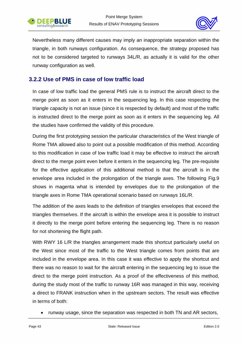
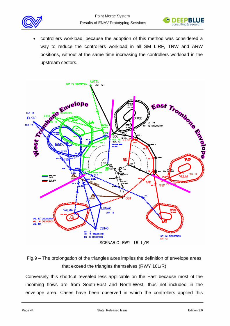
During the first prototyping session the particular characteristics of the West triangle of
Rome TMA allowed also to point out a possible modification of this method. According
to this modification in case of low traffic load it may be effective to instruct the aircraft
direct to the merge point even before it enters in the sequencing leg. The pre-requisite
for the effective application of this additional method is that the aircraft is in the
envelope area included in the prolongation of the triangle axes. The following Fig.9
shows in magenta what is intended by envelopes due to the prolongation of the
triangle axes in Rome TMA operational scenario based on runways 16L/R.
The addition of the axes leads to the definition of triangles envelopes that exceed the
triangles themselves. If the aircraft is within the envelope area it is possible to instruct
it directly to the merge point before entering the sequencing leg. There is no reason
for not shortening the flight path.
With RWY 16 L/R the triangles arrangement made this shortcut particularly useful on
the West since most of the traffic to the West triangle comes from points that are
included in the envelope area. In this case it was effective to apply the shortcut and
there was no reason to wait for the aircraft entering in the sequencing leg to issue the
direct to the merge point instruction. As a proof of the effectiveness of this method,
during the study most of the traffic to runway 16R was managed in this way, receiving
a direct to FRANK instruction when in the upstream sectors. The result was effective
in terms of both:
• runway usage, since the separation was respected in both TN and AR sectors,
Point Merge System
Results of ENAV Prototyping Sessions
Page 44 State: Released Issue Edition 2.0
• controllers workload, because the adoption of this method was considered a
way to reduce the controllers workload in all SM LIRF, TNW and ARW
positions, without at the same time increasing the controllers workload in the
upstream sectors.
Fig.9 – The prolongation of the triangles axes implies the definition of envelope areas
that exceed the triangles themselves (RWY 16L/R)
Conversely this shortcut revealed less applicable on the East because most of the
incoming flows are from South-East and North-West, thus not included in the
envelope area. Cases have been observed in which the controllers applied this
Point Merge System
Results of ENAV Prototyping Sessions
Page 45 State: Released Issue Edition 2.0
shortcut on the East with low traffic load. They found the strategy useful and effective
in these cases, but its application is limited to the traffic coming from North-East
(particularly from VELIM and KATAR).
With runways 34L/R the shortcut was appreciated as well. In this case it revealed
more applicable on the East than on the West. In addition with this runway
configuration two more issues have been observed that are worth to be reported in
this document:
• on the East a violation of the rule has been often observed, according to which
the traffic received the direct to merge point before entering the envelope. The
result was the traffic following a path external to the envelope but quite close to
the right side of the West triangle. No effects of this violation have been noticed
on the effective application of the PMS method.
• traffic from South-East re-routed to the West triangle could easily intercept the
localiser before joining the West triangle and reaching VANIA.
The following Fig.10 shows in green the envelopes created by the prolongation of the
triangles axes when runways 34 L/R are in use. The dot line represents the violations
described above.
The second violation – namely the localiser interception from the South - has not been
observed during the study since the controllers have been instructed to follow the
standard route and to insert the traffic into the sequencing leg. Their opinion was that
the shortcut would have smoothed the traffic management without negative effects on
the use of the PMS method.
It is interesting to notice that this use of the method opens a discussion on the
effectiveness of using the point merge technique in low traffic load conditions.
At the beginning of the study PMS has been proposed as a technique to be applied in
substitution of radar vectoring when the traffic load increases. Radar vectoring is then
restored when the traffic load decreases. It is evident that this preliminary idea raises
questions such as:
• which is the traffic threshold marking the need for a switch from radar vectoring
to PMS and vice-versa?
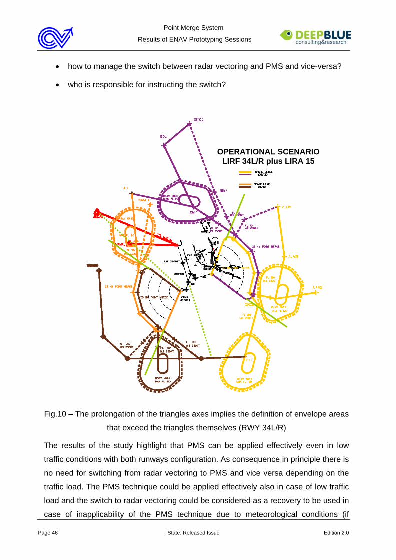
Point Merge System
Results of ENAV Prototyping Sessions
Page 46 State: Released Issue Edition 2.0
• how to manage the switch between radar vectoring and PMS and vice-versa?
• who is responsible for instructing the switch?
Fig.10 – The prolongation of the triangles axes implies the definition of envelope areas
that exceed the triangles themselves (RWY 34L/R)
The results of the study highlight that PMS can be applied effectively even in low
traffic conditions with both runways configuration. As consequence in principle there is
no need for switching from radar vectoring to PMS and vice versa depending on the
traffic load. The PMS technique could be applied effectively also in case of low traffic
load and the switch to radar vectoring could be considered as a recovery to be used in
case of inapplicability of the PMS technique due to meteorological conditions (if
OPERATIONAL SCENARIO LIRF 34L/R plus LIRA 15
Point Merge System
Results of ENAV Prototyping Sessions
Page 47 State: Released Issue Edition 2.0
necessary, see par.3.2.7) or other causes.
The following paragraphs present the results produced during the study when trying to
switch to conventional arrival management to PMS and vice versa. Both the
experiences reinforce the idea to keep using PMS as standard method for arrival
traffic management, independently from the traffic load.
3.2.3 Transition from conventional method to PMS and vice versa
The transition from conventional methods of arrival traffic management to PMS and
vice versa has been investigated during the fourth prototyping session. Two scenarios
have been implemented in order to analyse both the transitions. They focus on:
• transition to PMS in the morning due to forecast of traffic increase
• transition from PMS to conventional methods of arrival traffic management due
to contingency
Transition from conventional methods of arrival traffic management to PMS
Scope of the exercise was to re-create a typical morning situation, with the traffic
gradually increasing until the morning peak, and to define how to manage the
transition from conventional methods of arrival traffic management to PMS. A briefing
was arranged before the run in order to give the controllers information about the
scenario and share with them the objective of the exercise.
During the exercise the controller acting as SM LIRF adopted a defensive strategy
and decided to arrange the transition to PMS quite soon. This strategy was intended
to make the transition as smooth as possible. Actually the results were very positive
and the transition was managed in a very straightforward way.
After deciding to start the transition SM LRF informed the supervisor, all the
controllers of the arrival sectors and the controllers of the adjacent sectors. The arrival
controllers changed the maps on the radar screen, displaying triangles and point
merges. As soon as passing to PMS they managed the traffic giving it direct to merge
point instructions, as typical of low traffic load conditions. When the traffic increased
they started using the sequencing legs and SM LIRF regulated the access to the
triangles on the basis of the triangle capacity.
Point Merge System
Results of ENAV Prototyping Sessions
Page 48 State: Released Issue Edition 2.0
The process was very straightforward and simple and no penalisation has been
observed in the traffic. However the controllers pointed out that this positive result was
dependant on two possible risky activities, namely:
• a subjective decision of SM LIRF, who applied a defensive strategy and decide
to start the transition process when the traffic load was still low
• a good coordination among the team members, with SM LIRF informing
everybody and checking that every one was ready for the transition
If the transition were postponed or if SM LIRF was less keen on monitoring the others,
it cannot be ensured that the same results would have been collected. These
considerations enforced the controllers’ opinion already mentioned in previous
paragraph that it could be effective and safe to decide to use PMS as standard way of
managing the arrival traffic instead of introducing it when the traffic increases.
This choice would allow to full profit by the method without leaving room to risks. It
would seem particularly applicable when RWY 16L/R are in use. Conversely with
RWY 34L/R more downwind is possible, thus making the controllers less convinced of
the effectiveness of using PMS as standard method of arrival traffic management
even in low traffic conditions.
Transition from PMS to conventional methods of arrival traffic management
The transition from PMS to conventional methods of arrival traffic management
happened was tested in contingency. DME off were simulated so that a sudden
reverse to conventional methods of arrival traffic management was necessary.
Also in this case the transition was managed in a very straightforward way. SM LIRF
gave the information to TN controllers and SM LIRA. SM LIRA informed AR
controllers. The controllers changed the maps in their radar screens in order to cancel
triangles and point merges. Then they started radar vectoring the traffic. In their
opinion the situation was very simple to manage in the AR positions, slightly more
complex in the TN sectors where longitudinal and vertical separations had to be used.
It is interesting to notice that the execution of this scenario highlighted that the
modification of the radar screen display was a key issue for the success of the
transition. One of the controllers acting as AR did not change the map and presented
Point Merge System
Results of ENAV Prototyping Sessions
Page 49 State: Released Issue Edition 2.0
some problems of confusion in the management of the traffic since he was working
without the proper reference points. The controllers’ suggestion was to add a
functionality to quickly change the display (par. 3.6).
3.2.4 Use of PMS in case of go around
During the prototyping sessions several cases of go around have been simulated. The
management of these situations brought to the definition of two possible procedures to
be applied in case of go around. They concern the use of conventional radar vectoring
finalised to:
• traffic re-insertion into the sequence according to suitable available gap
• traffic re-insertion in the sequencing leg
Traffic re-insertion into the sequence in the triangle
In this case after the go around the AR sector controller radar vectors the aircraft in
order to re-insert it into the sequence already set in the triangle. Coordination among
SM, TN and AR sectors controllers is required in order to ensure the appropriate
spacing. All the sessions confirmed that this procedure is appropriate only in case
some spacing is already available in the sequence and/or minor adjustments are
sufficient to make it coherent with the spacing required for the traffic insertion. An error
in the identification of the hole or in its arrangement is likely to affect the whole traffic
management in the triangle, with evident negative results.
With RWY 16 L/R this procedure has been applied giving the aircraft a first clearance
of 6000ft and runway heading and then turning it in order to join the triangle. The
presence of traffic to LIRA implied a need for coordination between SM LIRF and SM
LIRA in order to avoid interferences, that otherwise was not necessary. In these cases
when the go around interested traffic from the East and was interfering with traffic to
LIRA, SM LIRF gave the aircraft 2 clearances instead of one. The first clearance was
to 3000ft and the second one to the final altitude coordinated with SM LIRA.
With RWY 34 L/R this procedure revealed applicable as well. Nevertheless the large
spacing required among the traffic due to the wind effect made it used less frequently.
All the studies have highlighted the need for giving SM LIRF the responsibility to
identify the spacing in the sequence where the aircraft will be re-inserted and to
Point Merge System
Results of ENAV Prototyping Sessions
Page 50 State: Released Issue Edition 2.0
communicate it to the other controllers. He can definitely take into considerations
possible suggestions of SM LIRA or AR controllers. Anyway, it is up to him to make
the final decision and communicate it to the others. This working method has the
twofold purpose to share the knowledge within the team and foster the overall
situational awareness. Many cases have been observed during the prototyping
sessions in which SM LIRF left the decision to AR controllers. This choice created
confusion in the go around management, change of the strategy on tactical basis,
poor situational awareness and limited mutual understanding among the controllers.
Conversely when SM LIRF has set the strategy of go around management, it has
been handled in a smooth way, with good levels of cooperation and situational
awareness among the controllers. This is the reason way this second strategy is worth
to be preferred.
Traffic re-insertion into the sequencing leg
In this case after the go around the AR sector controller radar vectors the aircraft
towards the sequencing leg. He then hands it over to TN sector controller who re-
inserts it in the sequencing leg at a spare level.
Two limits have been envisaged in this strategy by the controllers involved in the first
study and in the following ones. They concern respectively:
• fuel availability
• the need for making the aircraft climbing until the spare level and then descend
again to the merge point
The highlight of these limits brought the controllers to prefer the first strategy
considering it more effective than the second one in terms of both traffic management
and controllers workload. Nonetheless they also highlighted that:
• the applicability of the first strategy may not be guaranteed in case of busy
triangles
• the second strategy can be useful as standard procedure in case of go around
with communication failure.
For this reason both strategy are considered valid and worth to be taken into account.
It is interesting to notice that in applying both procedures the controllers tended to
Point Merge System
Results of ENAV Prototyping Sessions
Page 51 State: Released Issue Edition 2.0
respect the aircraft provenance. This means that if the go around involved traffic from
the East they tended to re-insert it into the East sequencing legs or triangle. Similarly if
the aircraft was from the West they tended to re-insert it into the West sequencing
legs or triangle. The third prototyping session has highlighted the possibility to use the
other triangle, if it smoothes the go around management. This consideration came out
from the observation that many go around interested the East triangle, that was at the
moment quite busy, while the other was quite empty. As consequence the
management of the go around was often quite penalising for the concerned aircraft.
Discussing this topic with the controllers they claimed that sending the aircraft
originally coming from the East to the West triangle was not instinctive for them, also
because of possible interferences with the current SIDs. But the topic is worth to be
taken into consideration and further investigated because this procedure could smooth
the traffic management.
3.2.5 Use of PMS in case of spacing increase
During the studies two different kinds of spacing increase have been simulated, with
different traffic load and conditions. They referred respectively to cases of:
• request of spacing increase for runway inspection
• change of runway spacing
In the first case the tower requested the controllers to make a gap of 12NM for runway
inspection. The nature of the inspection was mainly routine, thus there was some
leeway for the controllers to react. Seldom instead the inspection was exceptional,
meaning that the controllers had to promptly fulfil the tower’s request.
In the second case concerning the change of the runway spacing the tower informed
the controllers that the landing spacing was going to be changed, whether
immediately –due to contingency – or in a lapse of time to be coordinated with SM
LIRF.
The studies produced positive results in all the conditions.
Even in high traffic load conditions the controllers fulfilled the requests in a very
straightforward way and with low level of workload. This result has been confirmed
even in single runway operations and in extreme – and for some aspects not fully
Point Merge System
Results of ENAV Prototyping Sessions
Page 52 State: Released Issue Edition 2.0
realistic – cases, in which in busy traffic conditions the separation on the East
suddenly passed from 3 to 8NM or a separation of 12NM was requested for urgent
inspection.
According to the controllers’ opinion, using the PMS method facilitates them in dealing
with the request of spacing increase. Nevertheless for the successful management of
these events it is important that a standard way of reacting to the request is applied. In
other words, the introduction of the PMS method may make easier to satisfy the
tower’s request, but the controllers need to have clear and precise rules to follow.
The rules defined during the studies are reported hereafter.
Spacing increase for routine runway inspection
In case the tower requests a spacing increase for routine runway inspection SM LIRF
is responsible for fulfilling the request without at the same time penalising the traffic
too much or affecting the smooth application of the PMS method. In general in dealing
with the tower’s request his main tasks are the following:
• identifying the gap - it may be necessary to take some time before answering
to the tower in order to consult with the other controllers
• communicating the gap to the tower
• communicating the need of spacing increase due to runway inspection and the
gap identified to the other controllers concerned, giving precise indications on
how to adjust the traffic if necessary
• monitoring the situation in order to be sure that the separation is respected
The controllers involved in the studies tended to consider the identification of the gap
as the trickiest task of this process. Evidence has been collected that an error at this
stage may affect the effective and smooth application of the PMS method. For this
reason a few guidelines have been defined in order to standardise the controllers’
behaviour when dealing with this kind of situations as SM LIRF.
The preferable strategy to follow for not impacting too much on the traffic
management is to profit by a natural hole in the sequence - if available. This choice
ensures that the request can be fulfilled easily, with limited intervention on the traffic -
just to adjust it in case the natural hole is not perfectly correspondent to the spacing
Point Merge System
Results of ENAV Prototyping Sessions
Page 53 State: Released Issue Edition 2.0
requested and needs to be slightly enlarged.
In alternative, if the triangle is busy and no natural gap is available, the preferable
strategy to follow is to absorb the delay in the sequencing leg. This means that SM
LIRF identifies the aircraft after which the inspection will be executed and let the
following one navigating through the sequencing leg until the required spacing has
been reached. The larger is the spacing requested by the tower, the more it is
important for SM LIRF to choose as target one aircraft that can turn to the merge point
as soon as entering into the sequencing leg. If so, the following one has the whole
sequencing leg to absorb the delay and the risk to reach the end of the sequencing
leg without being able to turn is limited. Nevertheless should it happen, the advisable
strategy is to continue on the other sequencing leg at a spare level (par.3.2.1).
Some cases have been observed during the studies (particularly during the third one)
in which this guideline revealed difficult to apply because letting the following aircraft
navigating through the sequencing leg would have penalised the entire traffic flow. In
these cases the controllers preferred to create the gap by removing one or more
aircraft from the sequence and re-inserting it/them in the sequencing leg. This strategy
was considered appropriate and acceptable for the effective use of the PMS method,
provided that the traffic can be easily re-inserted in the sequencing leg.
Spacing increase for urgent runway inspection
In case of urgent runway inspection the tower communicates when the inspection has
to be executed. This means that the tower communicates or coordinates with SM
LIRF the target after or before which the requested spacing has to be ensured.
In these cases if the triangle is almost empty and the inspection profits by a natural
gap in the sequence, SM LIRF just informs the other controllers of the runway
inspection and monitors the situation in order to be sure that the gap is not absorbed.
On the contrary if the natural gap is not available, the preferable strategy to follow in
order to fulfil the request is to remove one or more aircraft from the sequence and re-
insert it/them in the sequencing leg.
Increase of runway spacing
In case of increase of the runway spacing SM LIRF is up to undertake different actions
Point Merge System
Results of ENAV Prototyping Sessions
Page 54 State: Released Issue Edition 2.0
depending on the traffic position with respect to the triangles.
Three phases have been identified, to which different actions have been associated.
• In the triangle
if the increase of spacing is so urgent to apply even to the traffic already in the
triangle - that is traffic that has already left the sequencing leg and is currently
navigating towards the point merge – SM LIRF identifies the aircraft that does
not comply with the required spacing, removes it from the triangle and arranges
its re-insertion in the sequencing leg.
This strategy has been considered the standard one and preferable. Other
strategies have also been observed during the studies. They both foresee the
use of conventional radar vectoring techniques: in one case with the purpose of
sending the aircraft from the East to the West runway after the eastern point
merge; in the other case with the purpose of increasing the spacing among the
traffic. The controllers involved in the study considered the first strategy
acceptable – provided that both tower and pilot have been previously informed
of both runway change and radar vectoring and agreed on the new strategy.
The second use of radar vectoring instead was considered unacceptable since
likely to impact on the whole traffic management. Radar vectoring within the
triangle is in fact likely to make TN and SM controllers not aware of AR
controllers’ behaviour and consequently uncertain on how to organise the other
traffic.
• In the sequencing leg
If the increase of spacing affects the traffic in the sequencing leg, the strategy
to follow is to absorb the delay in the sequencing leg. This means that the
traffic keeps on navigating through it until reaching the required separation from
the previous one in the sequence. Traffic arriving at the end of the sequencing
leg without being able to turn to the merge point has to be re-inserted it in the
other sequencing leg at a spare level.
The experience of the study revealed that this procedure may present some
defects of applicability when RWY 34L/R are in use due the wind effect
requiring large separations among the traffic in the east sequencing leg.
Point Merge System
Results of ENAV Prototyping Sessions
Page 55 State: Released Issue Edition 2.0
• Outside triangles and sequencing legs
SM LIRF evaluates the impact of the increased spacing on the triangle capacity
and limits the access to it accordingly. Traffic exceeding the triangle capacity is
re-routed to the other triangle and runway – if possible – or stopped at the
holding points.
With respect to the last topic, the prototyping sessions have highlighted that the
increase of the runway spacing may create some uncertainty to the controllers on the
actual separation to apply when runways 34L/R are in use. As already mentioned in
previous paragraphs in this case the wind value affected the aircraft performances on
the East triangle, thus requiring an enlargement of the spacing in the triangle in order
to reach the requested spacing on the ground. With standard separation of 3NM from
touchdown, the experience of the simulation highlighted that a separation of 6/7NM
was necessary within the east triangle. When the spacing increased to 8NM some
attempts have been necessary before finding the appropriate separation in the triangle
(finally set at 15NM). In the meantime the controllers had to cope with the inadequate
spacing by means of radar vectoring techniques within the triangle or even in some
cases removing the traffic from the sequence and re-insert it in the sequencing leg.
The observation of these cases brought to the consideration that a standard matrix
could be useful, providing the controllers with indications on the separation to apply in
the triangle depending on wind effects and separation requested from touchdown. It is
worth pointing out that the separations suggested in the matrix should be approximate
by excess, since the triangle conditions make easier for the controllers to reduce the
separation among the traffic than increasing it.
3.2.6 Use of PMS in case of runway change
Many cases of runway change have been observed during the studies conducted so
far. They have been mainly caused by:
• high traffic load in one of the two triangles
• problems of spacing in the triangle
• pilot’s request
• runway closure

Point Merge System
Results of ENAV Prototyping Sessions
Page 56 State: Released Issue Edition 2.0
In all these cases the runway change has been smooth and easy for the controllers,
who appreciated the standard way in which all of them behave and the result
produced in terms of effectiveness of the traffic management.
Detailed results concerning the four cases of runway change are provided hereafter.
Runway change due to high traffic load in the triangle
As discussed in paragraph 3.2.1 in high traffic load conditions the controllers tended to
re-route the traffic to the other triangle and runway. Causes for re-routing were triangle
capacity overload or high workload of the controllers (particularly those managing the
East part of Roma TMA, because involved in the management of the traffic to LIRA).
In these cases SM LIRF tended to make the decision of runway change quite in
advance, while planning the incoming traffic.
Discretional routings are available in the PMS operational scenarios to foster these
cases of triangle and runway change. Despite the general working method
recommending to link triangle and runway, all the prototyping sessions have
highlighted a tendency to apply it mainly on the East.
Discretional routings have been generally used to re-route the traffic from the East to
the West triangle. Conversely discretional routings from West to East have been rarely
used, almost always associated to delay actions for the concerned aircraft that would
have reached the point merge too early passing through the West triangle. The traffic
from the West planned to land on the East runway tended to be managed in the West
triangle and after the West point merge (FRANK or VANIA) to be cleared to the other
runway profiting by the runways connection.
This shortcut had the twofold purpose to balance the workload between East and
West TMA controllers and to avoid penalising the traffic. In some cases it has also
been used in conjunction with the direct to merge point instruction before the entrance
in the sequencing leg (par.3.2.2) in order to profit by natural gaps in the East
sequence that elsewhere would have not been filled.
The shortcut of using the West triangle to manage traffic for the East runway was
considered effective by the controllers involved in the studies and no negative or side
effects of it have not been detected.
Point Merge System
Results of ENAV Prototyping Sessions
Page 57 State: Released Issue Edition 2.0
Runway change due to problems of spacing in the triangle
As discussed in paragraph 3.2.4 the management of urgent requests of spacing may
require one aircraft to be removed from the sequence already set in the triangle. In
this case the standard procedure is to re-insert the traffic in the sequencing leg. This
procedure penalises the traffic quite a lot.
In order to avoid this penalisation the controllers can send the traffic to the other
runway, if available.
This strategy profits by the runways connection if the traffic concerned has to go from
the West to the East. On the contrary radar vectoring is necessary when the traffic is
re-routed from East to West runway. In this case in fact no runways connection is
foreseen and radar vectoring is the only means available. The application of this
strategy requires the controllers to coordinate with both tower and pilot in order to
ensure that they accept the runway change and the radar vectoring.
During the studies the controllers have often requested to add a connection from East
to West runway to use in case of contingency – as for instance the spacing increase
discussed in this paragraph. Actually in the original scenario the runway connection
was intended to be used in single runway operation, when only the East runway is
used. The possibility of using the West triangle to feed the East runway came out
during the studies as additional working method.
The recommendation for the next stage of the project is to discuss the actual need
for a runways connection from East to West, highlighting feasibility issues, possible
drawbacks and cases in which it could be useful
Runway change due to pilot’s request
In general if the runway change is associated to a pilot’s request the controllers have
been observed to try as far as possible to fulfil it.
Due to the association between triangles and runways the pilot who wants a runway
change has to make the request quite in advance, at least before entering the
sequencing leg. In this case the request tends to be managed as described above,
using the West triangle to feed the East runway and discretional routings to send the
traffic from the East requiring to land on the West runway to the West triangle. No
problems have been detected as associated to this strategy, but for some difficulties in
Point Merge System
Results of ENAV Prototyping Sessions
Page 58 State: Released Issue Edition 2.0
distinguishing this traffic from the one following the conventional routings. The
problem was mainly due to a usability defect of the label, that does not provide
information abut the runway on which the aircraft is planned to land. As described in
par.3.6 during the studies the controllers tended to make up to this defect with the
speed vector, but the results were sub-optimal due to the multiple and local use of it.
More complex than the case of early pilot’s request is the management of late pilot’s
requests, made up when the aircraft is already in the sequencing leg. Various
strategies have been tested during the studies to manage this particular situation.
According to the controllers’ opinion the most appropriate and prudent one is to
remove the aircraft from the triangle and re-insert it in the other sequencing leg.
However since the procedure penalises quite a lot the aircraft, it is important to advise
the pilot that it implies radar vectoring and a certain delay. Only after the pilot’s
acknowledge the procedure can be applied. In most cases during the studies the pilot
gave up the request of runway change, preferring to land on the other runway instead
of on the requested one with a large delay.
Runway change due to runway closure
One case of runway closure has been simulated during the fourth prototyping session.
It concerned RWY 34L and happened in a moment of quite dense traffic conditions.
The results were not as positive as expected.
The controller acting as SM LIRF focused first on the traffic in the triangle, trying to
identify where to insert the traffic from the West on the sequence for RWY 34R and
how to harmonise the two traffic flows. Since the East triangle was quite busy he
decided to use the sequencing legs to delay the traffic and merge the two traffic flows.
Traffic not yet in the triangles has been stopped at the holding points.
Unfortunately the effort of SM LIRF did not reveal enough to prevent the use of
extensive radar vectoring, particularly in the AR positions. This behaviour implied that
TN controllers lose their reference points for the use of PMS and started radar
vectoring the traffic as well. No reverse to PMS has been observed during the run.
This result presents some analogies with the first cases of go around managed during
the study. Also in that case the controllers tended to minimise the penalisation,
sharing it among the traffic, with negative results. Commenting the exercise during the
Point Merge System
Results of ENAV Prototyping Sessions
Page 59 State: Released Issue Edition 2.0
debriefing, the controllers admitted that for the effective execution of the scenario the
most effective strategy would have been based on a penalisation of the traffic in the
West triangle planned to land on RWY 34L. In their opinion a successful process
would have been managed as follows:
• traffic in the west triangle already navigating towards the point merge is
managed as a go around and reinserted in the sequencing leg of the most
convenient triangle
• traffic in the east triangle is managed as planned, inserting traffic originally
planned to RWY 34L in the sequence only in case of natural spacing available
• traffic in the west sequencing legs and planned to land on RWY 34L continues
navigating through them until the traffic in the east sequencing legs has been
managed; if necessary when arriving at the end of the sequencing leg it is re-
inserted in the other one
• all the traffic not yet in the sequencing legs stops at the holding point, until SM
LIRF authorises it to proceed to the approach.
The principle on which this process is based is clearly the same used and found
effective in case of go around. Extensive use of radar vectoring is to be avoided. Only
the traffic directly interested by the event has to be penalised in order to keep using
PMS effectively. This traffic is the one going around in one case and the one originally
planned to land on the runway that has been closed in the other case.
3.2.7 Use of the PMS method in case of radio failure
Radio failure has been simulated in the second and third prototyping sessions. In both
cases the radio failure happened on the East and concerned one aircraft just entered
in the sequencing leg.
According to the PMS working methods, the procedure in this case foresees the pilot
to fly the entire sequencing leg until the merge point, while the controllers plan and
control the rest of the traffic accordingly.
The results of the studies revealed that using the PMS method the management of the
radio failure was straightforward for the controllers and not critical at all. The main
difficulty was to arrange the rest of the traffic in order not to interfere with the aircraft in
Point Merge System
Results of ENAV Prototyping Sessions
Page 60 State: Released Issue Edition 2.0
radio failure. In this respect three main aspects are worth to be reported, that
impacted quite a lot on the traffic management in both the cases observed:
• the controllers presented evident uncertainty on the separation required after
the radio failure
• they have been disappointed when realised that parallel independent
approaches were occurring despite the radio failure
• SM LIRF pointed out poor involvement in the management of the radio failure
These common results brought to the conclusion that a standard behaviour is required
even in case of exceptional circumstances as the radio failure. In particular:
• SM LIRF should be aware of the situation, because his involvement is a pre-
requisite for him to be able to appropriately coordinate with the tower and
organise the traffic
• standard separation to be applied in case of radio failure should be defined
• parallel independent approaches should not be allowed in contingency
3.2.8 Use of PMS in case of bad weather and mixed equipped traffic
The controllers involved in the study often identified in the conditioned applicability of
PMS in certain circumstances (i.e. bad weather conditions and mixed equipped traffic)
one of its main drawbacks.
However it is interesting to notice that they tended to consider these drawbacks as
acceptable. They tended to view these limits as a tolerable side effect of the method
itself, definitely with rare probability to impair its acceptability or effectiveness.
This positive attitude was actually surprising. During the analysis of the first
prototyping session this result has been partially justified considering that the
controllers involved in study had not the chance to face these drawbacks and could
just discuss about them on a purely theoretical way. This lack of direct experience was
considered in short a possible factor influencing the controllers’ opinion on the
acceptability of the drawbacks themselves. For this reason the report contains a
recommendation for the next prototyping sessions to simulate cases of mixed
equipped traffic and bad weather conditions. This suggestion has the twofold purpose
Point Merge System
Results of ENAV Prototyping Sessions
Page 61 State: Released Issue Edition 2.0
to evaluate the actual impact of these conditions on the use of the PMS method and to
check the results of the first prototyping session about the acceptability of the
drawbacks of the method.
Following this advice bad weather has been simulated in both second and third
prototyping sessions, while cases of mixed equipped traffic have been simulated
during the fourth prototyping session.
The results were in both cases coherent with those collected during the first
prototyping sessions. MSP confirmed to be not fully applicable in these cases, but this
limit was not considered as impairing its effectiveness or acceptability. In case of
mixed equipped traffic the controllers did not found problems in radar vectoring some
aircraft while at the same time managing the rest by means of PMS. In case of bad
weather they claimed to consider PMS as a support, even if used in a non standard
way or partially. Details on the way the two scenarios have been managed are
provided hereafter.
MSP in case of bad weather
Bad weather has been simulated in the East triangle, in both runways configurations.
At the beginning of the exercise the supervisor informed the controllers about possible
bad weather to the East, not yet impacting on the arrival traffic management in Rome
TMA. After a while some arrival traffic reported bad weather and asked to avoid it.
The bad weather was planned to expand over the East triangle, from about FL90 up.
This means it was not planned to affect the West triangle and point merge. The way
the bad weather has been implemented was intended to allow the controllers to
decide whether to keep using the PMS method -even though in non standard way- or
instead than reverting tout court to radar vectoring. In both cases they have opted for
the first strategy, since just the possibility to use the triangle or just the point merge
was considered of great support for them.
The controllers’ reaction to the bad weather was different in the two cases.
During the second prototyping session, based on runway configuration 16L/R, SM
LIRF initially stopped the traffic in holding before the entrance to the East triangle. He
then decided to converge all the traffic destination LIRF to the West triangle. Not all
the traffic however was planned to land on the west runway. The traffic was balanced
Point Merge System
Results of ENAV Prototyping Sessions
Page 62 State: Released Issue Edition 2.0
on the two runways, since the tower accepted SM LIRF’s request to temporary reduce
to 3NM the spacing required on RWY 16R. All the traffic was managed in the West
triangle making couples of traffic to RWY 16R and 16L, flying the sequencing leg
vertically separated. TNW gave the direct to instruction to the aircraft of each couple
almost at the same time and then instructed them the descent to two different flight
levels: 5000ft to the traffic going to FRANK and landing on RWY 16R, 6000ft to the
traffic going to STAIR and landing on RWY 16L. He then handed over the traffic to
ARW, who managed the couples flying vertically separated within the triangle. After
FRANK, ARW cleared the aircraft for RWY 16L to further descend to 4000ft and
handed it over to ARE. ARE managed the final part of the sequence to RWY 16L and
supported TNE in dealing with traffic to LIRA whose management was affected by the
bad weather conditions.
This strategy revealed effective. The traffic was managed in a smooth way and no
large delays have been recorded. Nevertheless two main limits have been noticed.
The first limit concerns the distinction of traffic to RWY 16L and 16R. As all the traffic
entered the west sequencing legs at standard levels and the label did not provide
indication of the runway (par. 3.6), TNW had some troubles in distinguishing traffic to
the two runways. He used the speed vector but it was not effective enough. Also the
support of SM LIRF revealed unfit for this task since many cases have been observed
in which SM LIRF was confused and did not remember the traffic distribution on the
runways.
The other limit highlighted during the application of this strategy concerns the tasks
distribution among the AR controllers and their cooperation. In the particular case
observed during the study the controllers workload remained at acceptable levels.
Nevertheless the workload distribution among ARW and ARE was clearly unbalanced.
Since all the traffic to LIRF was managed in the West triangle ARW was very busy.
The same level of workload was not perceived by ARE who merely managed the final
part of the sequence to RWY 16L (from FRANK to the runway) and supported TNE in
dealing with traffic to LIRA. This unbalanced level of workload impacted on their
cooperation since ARW was so busy to have difficulties in communicating with ARE.
As consequence the two controllers appeared quite independent and with a poor
mutual awareness.
Point Merge System
Results of ENAV Prototyping Sessions
Page 63 State: Released Issue Edition 2.0
During the third prototyping session, based on runway configuration 34L/R, SM
LIRF opted for a mixed mode solution.
The solution adopted in the second prototyping session was in this case less
applicable since the triangles configuration did not allow to easily re-route the traffic
from the East to the West triangle. This strategy has been applied for some aircraft,
mainly from the South, that could easily follow the discretional routing. It would have
instead implied a long re-routing in case of traffic from East. As consequence this
traffic has been managed by means of conventional radar vectoring technique, having
as point of reference the point merge SHARA. This means that TNE kept making the
sequence on SHARA but did it using radar vectoring instead of sequencing legs,
triangles and distance rings. Of course the adoption of radar vectoring for bad weather
avoidance did not allow to have a sequence in which each traffic was 5NM from the
previous one and to the next one. In some case radar vectoring to the west runway
have been necessary since two aircraft were too close to land on runway 34R.
Nevertheless since most of the traffic tended to fly in a corridor external to the triangle
the situation appeared very ordered and calm.
MSP in case of mixed equipped traffic
In case of mixed equipped traffic the traffic not PRNAV equipped has been radar
vectored according to the conventional method of arrival traffic management. The
controllers did not find it difficult, nor risky. The only aspect remarked as important to
take into consideration is the need for keeping SM LIRF informed about the traffic not
PRNAV equipped and about the way it will be managed. This is a key aspect for
allowing him to properly organise the traffic in the triangles.
3.2.9 Flexible use of the PMS method
Concerning the flexible use of the method the results of the second and third
prototyping sessions have completely confirmed what already came out during the
first study.
The controllers involved in all the studies have often highlighted that introducing the
PMS method may imply a certain loss of flexibility with respect to the open loop
vectors currently used (par. 3.1). Nonetheless this loss of flexibility has been
considered acceptable because counterbalanced by evident benefits in terms of
Point Merge System
Results of ENAV Prototyping Sessions
Page 64 State: Released Issue Edition 2.0
workload reduction and efficiency of the arrival traffic management.
In addition one other reason contributed to make the method acceptable and domain
suitable for the controllers. It was the possibility of a flexible use of the method.
In the previous paragraphs, the effectiveness of the PMS method has been described
as strictly dependent on the application of its basic principles, namely:
• the pre-sequencing according to which the upstream sectors hand the traffic
over to TMA sectors with a spacing of at least 7NM, steady and at predefined
speed and flight level,
• the use of first in first out principle and distance ring while the aircraft is in the
triangle
• the association between triangle and runway (but for cases of pilot’s request
and runway balancing)
• the use of triangles capacity, segments of the sequencing leg and triangles as
trigger for SM LIRF intervention (whose need came out during the study).
In general the respect of these rules guarantees the successful application of the
method. Nonetheless it may also happen that these rules are violated. In these cases
all the prototyping sessions have revealed that the method can be quite flexible.
Some cases have been observed during the prototyping sessions in which the method
has been successfully applied notwithstanding violations in the application of its basic
rules. In particular these cases concerned:
• violation of the pre-sequencing rule
Two different cases of inappropriate pre-sequencing have been observed
during the study.
In the first case 2 aircraft have been handed over to TN sector one above the
other, meaning that they entered in the sequencing leg at the same time and on
the same point, but at different flight levels. TN controller managed the situation
in two steps. He quite soon instructed the first aircraft (that was steady at the
pre-defined flight level) to turn to the merge point and then to descend. He left
the other one continuing to descend to the flight level of the sequencing leg
while flying through it. When the first aircraft reached the distance ring, he
Point Merge System
Results of ENAV Prototyping Sessions
Page 65 State: Released Issue Edition 2.0
cleared the other aircraft direct to merge point instruction and then descent.
In the second case the inappropriate pre-sequencing affected most of the
inbound traffic to LIRF, since it was due to bad weather in the upstream
sectors. Also in this case the controllers continued managing the traffic with
PMS, using the sequencing leg to appropriately sequence the traffic. They
found the method comfortable and reliable. They also claimed that the key
element for the effective application of such flexible use of the sequencing leg
was the respect of the triangle capacity (par.3.2.1).
• violation of the first in first out rule
In this case two aircraft entered opportunely pre-sequenced in the sequencing
leg. Since the first one was Heavy, the TN sector controller decided to violate
the first in first out rule. As consequence he gave the direct to merge point
instruction to the second aircraft first and then to the other in order to profit by a
hole in the sequence.
• violation of the association between triangle and runway
In this case SM LIRF coordinated with the upstream sector controller that one
traffic coming from North-West and expected to land on East runway was
managed within the West triangle and then, after FRANK/VANIA sent to East
runway. The upstream sector controller managed it accordingly, handing it over
to the TN sector controller opportunely separated from traffic to the West
runway. The TN sector controller, knowing that the two aircraft were expected
to land in two different runways, and in agreement with the SM LIRF, gave the
direct to instruction to the two aircraft almost at the same time. He then
instructed them the descent to two different flight levels: 5000 to the aircraft
landing on the West and 6000 to the other one. He then instructed this latter to
further descend to 4000ft after the point merge.
• Vectoring inside the triangles
In this case some aircraft have been radar vectored inside the triangles, while
flying from one distance ring to the other in order to adjust the sequence or to
create the spacing for a go around to be inserted. Similarly other flights have
been slightly vectored in the final path for spacing or to be re-routed to the
Point Merge System
Results of ENAV Prototyping Sessions
Page 66 State: Released Issue Edition 2.0
West runway – in exceptional cases.
• Violation of triangles capacity
In this case due to external events (namely go around or runway inspection)
the triangle revealed temporary overloaded and some aircraft arrived at the end
of the sequencing leg. The TN sector controller radar vectored the traffic, as
extending the sequencing leg, and then re-inserted them into its part direct to
the merge point.
It is interesting to notice that these violations have not been perceived as problematic.
On the contrary the controllers tended to consider these cases as a proof of the
possibility to use the method in a flexible way when necessary. It was considered an
advantage of the technique, that though rigid allows to violate its own rules if
necessary and in sporadic cases, well coordinated with SM LIRF. What is interesting
to notice is that these violations were considered effective if applied in exceptional
situations and well coordinated internally to the team. Conversely they were
considered likely to compromise the effectiveness of the method if applied in a
systematic way and without coordination with the rest of the team.
The recommendation for the next stage of the project is to include this topic in the
training package, clearly highlighting that the method is rigid but seldom can be used
in a flexible way if necessary. Systematic violations are not allowed since they are
affecting the effectiveness of the method itself.
Point Merge System
Results of ENAV Prototyping Sessions
Page 67 State: Released Issue Edition 2.0
3.3 Appropriateness of roles and working methods
Roles and working methods applied proposed at the beginning of the study were
based on the following principles:
• the upstream sectors controllers (collected in one feeder position during the
prototyping sessions) pre-sequence the arrival traffic at a minimum distance of
7NM and hand it over to TN sector controllers at a pre-defined flight level and
speed (both conditions reached at least 10NM before the sequencing leg)
• TN sector controllers manage the aircraft entrance into the sequencing legs
and the navigation through the sequencing legs until the instruction to the
merge point
• AR sector controllers adjust the sequence with speed reductions
• SM LIRF coordinates with upstream sectors and SM LIRA, passes relevant
information to TNE and ARE controllers and manages the runway balancing if
necessary
• SM LIRA coordinates with LIRA TWR and SM LIRF, and passes relevant
information to TNE and ARE controllers. He is moreover responsible for the
sequence to LIRA.
These roles and working methods revealed effective and appropriate. The controllers’
opinion was that though requiring some adjustments, they are basically adequate for
the effective application of the PMS method and also acceptable and suitable to be
used in Rome TMA. This high acceptability largely depends on the choice of
maintaining continuity with the current roles and working methods applied in Rome
TMA. This choice revealed successful and contributed to make the controllers well-
disposed towards the new method of arrival management, considering it as an
evolution of the current one.
The adjustments required mainly concerned the use of these working methods.
Several cases have been observed in all the studies in which the workload tolerance
of one controller or conversely the defensive attitude of another one have brought to
unsuccessful results in terms of effective application of the method and consequently
of smooth arrival traffic management. Good results have been instead obtained when
Point Merge System
Results of ENAV Prototyping Sessions
Page 68 State: Released Issue Edition 2.0
everybody played his own role according to predefined and precise rules, allowing the
others to have correct expectations on which planning their own work.
These considerations convinced the controllers of the need to apply these working
methods in a quite rigid way and to identify in the standardisation of the controllers’
performances a pre-requisite for the effective application of the PMS method. The
standardisation ensures in fact mutual awareness, teamwork among the controllers
and most of all predictability of the controllers’ behaviour.
The application of this requirement implies a radical cultural change in the TMA
controllers, currently used to be proud of their creativity and workload tolerance while
managing the arrival traffic. At present this cultural change foreshadows as the real
challenge for the application and acceptance of the method.
The recommendation for the next stage of the project is to take into consideration the
importance of the standardisation of the controllers’ performances for the successful
application of the method, and to point out at the same time the effort that this change
implies at cultural level.
In the following there is a presentation of the detailed results of the prototyping
sessions concerning roles and working methods of SM LIRF, SM LIRA, TN and AR
sector controllers. These results have been structured per role in order to facilitate the
presentation of the results. The last part concerns the use of the method in single
runway operations.
Role and working methods of SM LIRF and SM LIRA
During the study SM LIRF played a key role for the effective application of PMS. He
was considered a master coordinator and confirmed to be the heart of the
configuration, both in single runway and in full runways operational scenarios.
With low traffic load his role was quite marginal, since the controllers managed the
traffic in a straightforward way according to the PMS method. His role was instead
more decisive and strategic for the effective management of the arrival traffic, when
the traffic increased and/or in case of particular events. In these cases in fact he was
responsible for:
• setting the strategy, deciding whether to apply runway balancing and/or to use
Point Merge System
Results of ENAV Prototyping Sessions
Page 69 State: Released Issue Edition 2.0
the holding,
• coordinating the application of this strategy with the adjacent sectors.
The new rules defined during the various studies based on triangles capacity and use
of sequencing leg and triangle (par. 3.2.1) supported him in this task. In fact
organising the traffic on the basis of more objective and standardised criteria of traffic
management implies the effects of:
• standardising the SM LIRF behaviour
• increasing the teamwork in the TMA positions thanks to the possible
anticipation of SM LIRF behaviour
The two effects are strictly interconnected. Since the SM LIRF tends to behave in a
standard way, applying the basic principles of the PMS method, TMA sectors
controllers are able to anticipate his behaviour and vice versa. This anticipation has
been observed to increase the teamwork and reduce the controllers’ workload, as
everybody had correct expectations on the others’ behaviour, could organise his own
work accordingly and had limited need for internal explicit coordination.
This ability of understanding and anticipating the other controllers’ behaviour is
expected to have positive effects on safety, since introduces mutual control and
redundancy. Nevertheless also a side effect has been observed. Knowing and
understanding the SM LIRF’s work brought sometimes the TMA sectors controllers to
bring their own decision forward, objecting on the effectiveness of the strategies
proposed by SM LIRF.
This kind of over-control, considered superfluous and ineffective, was quite evident
during the first prototyping session and required to often remark the role of SM LIRF
and the need for the others to comply with the strategy set. Considering the
experience of the first prototyping session and the recommendation that it produced,
in the training of the following sessions the concept of SM LIRF predominance has
been stressed, with evident positive results during the studies. Very few cases of
redundancy have been observed after that. Conversely, knowing the SM LIRF role
and understanding the reasons of his predominance, the other controllers tended to
apply a proactive behaviour, providing him with suggestions that he then was free to
evaluate and further accept or reject in the light of his broad view of the traffic.
Point Merge System
Results of ENAV Prototyping Sessions
Page 70 State: Released Issue Edition 2.0
The recommendation for the next stage of the project is to stress the concept of SM
LIRF predominance during the training.
It is worth underlining that during the first prototyping session a similar phenomenon of
redundancy has been often observed between SM LIRF and SM LIRA. The controller
playing this latter role often tended to substitute to the first one in his key tasks (i.e.
runway balancing) with the results of:
• increasing the phone communication between the two
• partially failing his role of mediation between TNE and ARE
This problem has been solved during the study remarking the strategic role of the SM
LIRF with respect to SM LIRA and slightly changing their working methods. The
modification introduced mainly consisted in making SM LIRA responsible for passing
the information received from SM LIRF not only to TNE and ARE but also to ARW. In
that case the modification revealed effective and both problems of ARW awareness
and redundancy between SM LIRF and SM LIRA have been solved.
Following the recommendation of the first prototyping session, during the second and
the third prototyping sessions this modification has not been applied in order to
evaluate the effect of the addition of traffic to LIRA on the redundancy between the
two roles. The studies revealed that the addition of traffic to LIRA largely contributed
to limit the redundancy, particularly during the third prototyping session and in full
runway configuration cooperation.
Nevertheless the same problem of information exchange noticed during the first
prototyping session tended to be confirmed. In general no problems have been
noticed when the information goes from AR controllers to the others (for instance in
case of go around). Conversely the communication was less immediate and effective
when goes from TN controllers or SMs to the others. Many cases have been recorded
in which ARW has not received the information in time or even at all.
The cause of this problem has been identified in the working methods adopted,
particularly those of SM LIRF.
According to the working methods, SM LIRF is responsible for setting the strategy and
communicating relevant information and instructions to the other controllers. This
Point Merge System
Results of ENAV Prototyping Sessions
Page 71 State: Released Issue Edition 2.0
communication is supposed to be direct with TNW and ARW controllers, while
mediated by SM LIRA with TNE and ARE controllers.
Confirming what already noticed during the first prototyping session, both the studies
highlighted that while working as SM LIRF the controllers tended to forget to pass
information to ARW controller. The communication was instead straightforward and
often tacit with TNW controller. In some cases, particularly in single runway operation,
the mediation of SM LIRA in passing the information from SM LIRF to TNE and vice
versa was considered a bottleneck of the process.
In order to solve the problem a modification has been introduced and tested during the
third prototyping session, according to which was the AR controller who first received
the information in charge to pass it to the other. This solution, though improving the
process, was however not perfect. On the basis of this consideration at the end of the
third prototyping session another solution has been proposed to solve this problem. It
is quite similar to the one suggested during the first prototyping session and consists
in giving:
• SM LIRF the task to communicate with both TN controllers and SM LIRA
• SM LIRA the task to communicate with both AR controllers and SM LIRF
This new working method revealed effective during the fourth prototyping session, in
which the process resulted speeded up and more efficient. SM LIRF was able to
easily communicate with both TN controllers, while SM LIRA ensured that both AR
controllers were aware of relevant situations and/or instructions. The application of
this working method required changes in the room layout that are described in par.3.5.
Role and working methods of TNW/TNE and ARW/ARE
During the prototyping sessions TN and AR controllers applied the standard working
methods associated to PMS.
According to these working methods each TN sector controller instructs the aircraft to
turn to the merge point, after appreciating the turn instructs it to descend (to the merge
point or to the intermediate step depending on the operational scenario) and hands it
over to AR sector controller. AR controller manages the aircraft descent in the triangle,
adjusting its speed in order to keep the separation required.
Point Merge System
Results of ENAV Prototyping Sessions
Page 72 State: Released Issue Edition 2.0
These working methods confirmed to be effective and applicable. The addition of
radar minima constraints did not affect the appropriateness of the working methods
and was not perceived by the controllers as a relevant factor of workload increase.
A few problems have been noticed during the studies due to the fact that all TN and
AR controllers often tended to forget to update the system with the clearances (i.e.
speed or routing) given to the traffic. When reasoning about this behaviour the
controllers tended to mark it as heritage of the current work in the control room, where
paper strips are still used to manage the arrival traffic. The same argument has been
used to explain the problem of communication flow described in previous paragraph.
Updating the paper strip and sharing it with the colleagues is a means to ensure
mutual knowledge and situational awareness.
During the studies the controllers tended to count on the same mutual and situational
awareness without considering that paper strips ensuring it were not available. As a
consequence problems of mutual and situational awareness have been pointed out,
with consequent increase of phone communications among the TMA controllers.
System update and verbal communication among the controllers revealed then crucial
for the success of the work.
The recommendation for the next stage of the project is to stress the need of system
update for the effective application of the method. The system update is moreover a
pre-requisite for the use of AMAN.
Roles and working methods in single runway operations
Applying the PMS method in single runway operations confirmed to be much more
complex than with full runway configuration. The difficulty was associated to the
definition of the arrival sequence that was less straightforward and evident than when
each triangle is almost univocally associated to one runway.
The operational configuration used during the study was based on 5 working
positions, namely TNW, SM LIRF, AR, SM LIRA and TNE. In this configuration each
TN sector controller was responsible for managing the traffic in the sequencing legs
according to the sequence arranged by SM LIRF. The final part of the sequence was
managed by the AR controller, who also managed the traffic inbound to LIRA.
The application of these working methods produced positive results, highlighting the
Point Merge System
Results of ENAV Prototyping Sessions
Page 73 State: Released Issue Edition 2.0
effectiveness of using two triangles to feed one runway. In particular the following
requirements have been elicited:
• Build the sequence on the basis of pre-defined and well known principles
The standard PMS principle FIFO has proven to be effective to make all the
controllers aware of the sequence. A further principle has also been added
during the study considering whether the traffic is entering in the internal or in
the external sequencing leg. According to this principle, named Inner Outer
(IO), in case of two aircraft entering two different sequencing legs at the same
time it is preferable to serve first the one in the inner sequencing leg. The use
of these principles fostered the cooperation among the team, contributed to
make the two SMs sharing the same view of the sequence and most of all to
reduce the need for verbal communication.
• Have a director of the traffic sequencing, able to deviate from standard principles if necessary
On the basis of the positive results got during the study applying the standard
FIFO and IO principles, a test has been arranged consisting in allowing TN
controllers to build the sequence on their own. Purpose of the test was to
investigate whether these principles are sufficient for the effective application
of the method in single runway operations. The results were negative. These
principles resulted important for the teamwork, as they introduce a common
view of the sequence once the traffic is in the sequencing leg. The traffic
arrangement before the entrance to the sequencing leg and the management
of not perfectly standard situations require however the work of a director.
• Consider the wind effects on traffic performances
With RWY 34R/L the traffic management has been deeply conditioned by the
effects of the wind. As effect of the wind the traffic in the same triangle tended
to have different performances, since the one from the North was faster than
the one from the South. These different performances of the traffic affected the
feasibility of basing the arrangement of the sequence on the PMS principles –
FIFO and IO – that revealed effective with RWY 16L/R. In this case in fact the
traffic from the South tended to have an advance on the traffic from the North.
Point Merge System
Results of ENAV Prototyping Sessions
Page 74 State: Released Issue Edition 2.0
As consequence of the heterogeneous traffic and of the lack of pre-defined
and shared principles, the sequence was less standard and univocal than in
the previous cases, with evident consequences in terms of mutual and
situational awareness, teamwork and communication. Several cases of
misunderstanding and redundancy have been noticed during the third
prototyping session between SM LIRF and SM LIRA, mainly due to the lack of
a common view of the sequence. The problem was caused by the working
methods and room layout adopted. In the fourth prototyping session in fact the
same problem has not been noticed since changes have been introduced in
order to allow SM LIRF to communicate directly with both TN controllers,
without any need for the intermediation of SM LIRA. A further improvement is
expected as result of the modification of the system HMI allowing SM LIRF to
show and update the sequence in the radar screens of the TMA controllers
(par.3.5).
• Allow a flexible management of traffic to LIRA
The study revealed that with dense traffic load AR controller may be
overloaded by the need to manage both traffic to LIRF in the triangle and traffic
to LIRA, by means of conventional techniques. Some cases have been
observed in which the management of traffic to LIRA distracted AR from the
sequence to LIRF or vice versa. In order to avoid this problem the working
methods have been slightly changed during the study in order to allow:
o TNE controller to manage traffic to LIRA at least until setting the
sequence
o SM LIRF to balance the traffic in the triangles in order to avoid to
overload TNE
This new working method revealed effective during the study. For TNE
managing the traffic to LIRA was not a problem, particularly if the amount of
traffic in the east triangle was limited by SM LIRF on the basis of the triangle
capacity. AR could focus on the last part of the sequence to LIRF and also to
LIRA, this latter if possible. The coordination between AR and TNE is essential
for the success of the traffic management. Cases have been observed in which
after a proper coordination the sequence to LIRA has been completely
Point Merge System
Results of ENAV Prototyping Sessions
Page 75 State: Released Issue Edition 2.0
managed by TNE, with positive outcomes in terms of both traffic management
and workload distribution among the controllers. Other cases have also been
observed in which the traffic was completely managed by TNE, but without
previously coordinating with AR. In these cases the results were not positive,
since AR tended to lose situational awareness. The controllers suggested to
extend this modification also to the working methods applied with full runways
configuration.
The final agreement was to:
o give TNE/W the responsibility to manage the first part of the sequence
to LIRA, until interesting the flight levels of the sequencing legs
o give ARE/W or AR (in case of single runway operations) the
responsibility to manage the last part of the sequence to LIRA whose
traffic is at flight levels below the sequencing legs
o allow a flexible allocation of the traffic to LIRA between TNE/W and
ARE/W (or AR), on the basis of their respective workload.
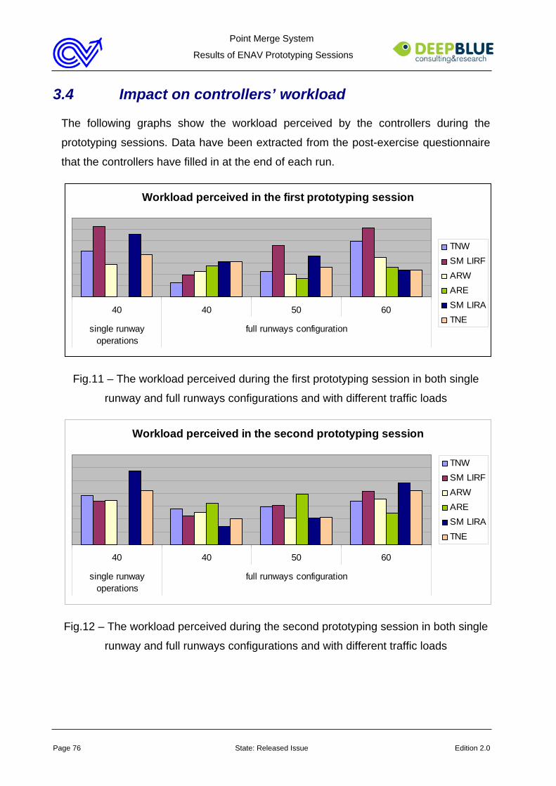
Point Merge System
Results of ENAV Prototyping Sessions
Page 76 State: Released Issue Edition 2.0
3.4 Impact on controllers’ workload
The following graphs show the workload perceived by the controllers during the
prototyping sessions. Data have been extracted from the post-exercise questionnaire
that the controllers have filled in at the end of each run.
Workload perceived in the first prototyping session
40 40 50 60
single runwayoperations
full runways configuration
TNWSM LIRFARWARESM LIRATNE
Fig.11 – The workload perceived during the first prototyping session in both single
runway and full runways configurations and with different traffic loads
Workload perceived in the second prototyping session
40 40 50 60
single runwayoperations
full runways configuration
TNWSM LIRFARWARESM LIRATNE
Fig.12 – The workload perceived during the second prototyping session in both single
runway and full runways configurations and with different traffic loads
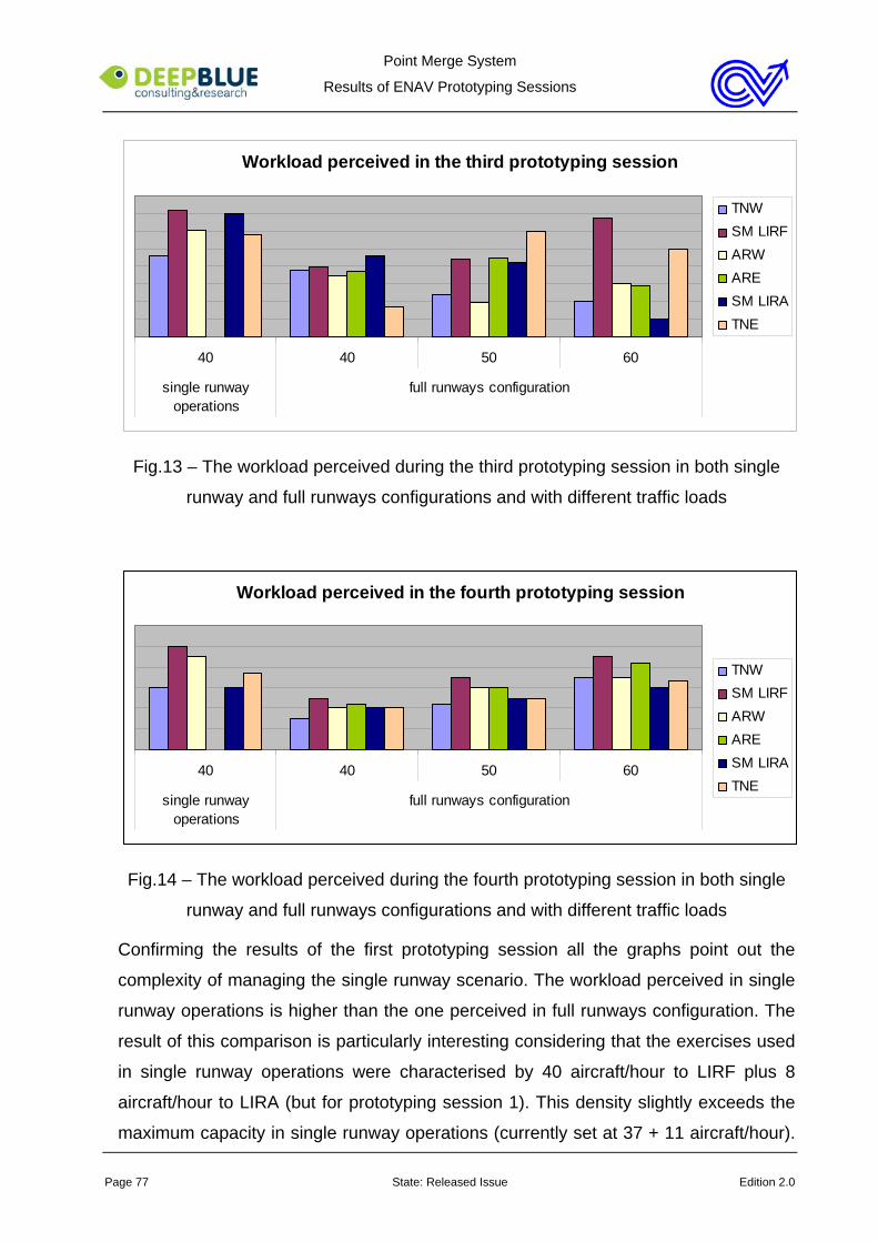
Point Merge System
Results of ENAV Prototyping Sessions
Page 77 State: Released Issue Edition 2.0
Workload perceived in the third prototyping session
40 40 50 60
single runwayoperations
full runways configuration
TNWSM LIRFARWARESM LIRATNE
Fig.13 – The workload perceived during the third prototyping session in both single
runway and full runways configurations and with different traffic loads
Workload perceived in the fourth prototyping session
40 40 50 60
single runwayoperations
full runways configuration
TNWSM LIRFARWARESM LIRATNE
Fig.14 – The workload perceived during the fourth prototyping session in both single
runway and full runways configurations and with different traffic loads
Confirming the results of the first prototyping session all the graphs point out the
complexity of managing the single runway scenario. The workload perceived in single
runway operations is higher than the one perceived in full runways configuration. The
result of this comparison is particularly interesting considering that the exercises used
in single runway operations were characterised by 40 aircraft/hour to LIRF plus 8
aircraft/hour to LIRA (but for prototyping session 1). This density slightly exceeds the
maximum capacity in single runway operations (currently set at 37 + 11 aircraft/hour).

Point Merge System
Results of ENAV Prototyping Sessions
Page 78 State: Released Issue Edition 2.0
A lower level of workload was perceived in both cases with full runways configuration,
even with a density of 60 + 13 aircraft/hour, that largely exceeds the maximum
capacity of this operational scenario (currently set at 54 + 11 aircraft/hour ).
Looking at the results gathered in single runway operation it is evident that in the third
prototyping session all the controllers tended to perceived a higher workload than in
the other prototyping sessions. This difference from the previous two was mainly due
to the wind effect. As effect of the wind in fact traffic from North and South tended to
have heterogeneous performances, thus impairing the controllers from applying the
standard PMS principles First In First Out and Inner Outer. The lack of standard
principles implied two main consequences: redundancy among the controllers and
increase of coordinations. These factors are considered the main cause of workload
increase. In the fourth prototyping session the positive effect of the revised working
methods and room layout can instead be noticed. The wind effect continued to be
present but its impact on controllers’ workload was definitely lower since the new
working methods and room layout made the coordination easier and faster.
A further aspect that is interesting to discuss comes out from the comparison of the
workload perceived in single runway operations during the first and the second
prototyping sessions, based on the same operational scenario.
It is evident that the results of the two graphs are mostly coherent, but for SM LIRF
workload that in the second prototyping session was quite lower than in the first
prototyping session. This difference has been explained as the combined effect of two
factors:
• the introduction of the Inner Outer principle
• the reduction of the redundancy with SM LIRA, that largely impacted on SM
LIRF’s workload during the first session
In the graph of the second prototyping session SM LIRA’s workload is still high but this
is considered partially due no more to the redundancy with SM LIRF, rather to the
management of traffic to LIRA and to the need to pass the SM LIRF’s instructions to
TNE and ARE controllers.
The graphs offer also some other insights concerning the application of the PMS
method in full runways configuration.
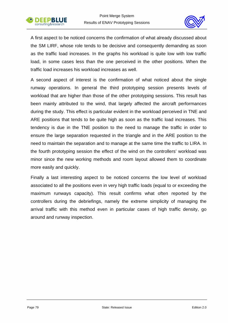
Point Merge System
Results of ENAV Prototyping Sessions
Page 79 State: Released Issue Edition 2.0
A first aspect to be noticed concerns the confirmation of what already discussed about
the SM LIRF, whose role tends to be decisive and consequently demanding as soon
as the traffic load increases. In the graphs his workload is quite low with low traffic
load, in some cases less than the one perceived in the other positions. When the
traffic load increases his workload increases as well.
A second aspect of interest is the confirmation of what noticed about the single
runway operations. In general the third prototyping session presents levels of
workload that are higher than those of the other prototyping sessions. This result has
been mainly attributed to the wind, that largely affected the aircraft performances
during the study. This effect is particular evident in the workload perceived in TNE and
ARE positions that tends to be quite high as soon as the traffic load increases. This
tendency is due in the TNE position to the need to manage the traffic in order to
ensure the large separation requested in the triangle and in the ARE position to the
need to maintain the separation and to manage at the same time the traffic to LIRA. In
the fourth prototyping session the effect of the wind on the controllers’ workload was
minor since the new working methods and room layout allowed them to coordinate
more easily and quickly.
Finally a last interesting aspect to be noticed concerns the low level of workload
associated to all the positions even in very high traffic loads (equal to or exceeding the
maximum runways capacity). This result confirms what often reported by the
controllers during the debriefings, namely the extreme simplicity of managing the
arrival traffic with this method even in particular cases of high traffic density, go
around and runway inspection.
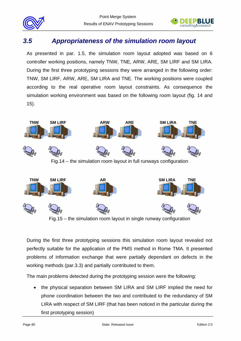
Point Merge System
Results of ENAV Prototyping Sessions
Page 80 State: Released Issue Edition 2.0
3.5 Appropriateness of the simulation room layout
As presented in par. 1.5, the simulation room layout adopted was based on 6
controller working positions, namely TNW, TNE, ARW, ARE, SM LIRF and SM LIRA.
During the first three prototyping sessions they were arranged in the following order:
TNW, SM LIRF, ARW, ARE, SM LIRA and TNE. The working positions were coupled
according to the real operative room layout constraints. As consequence the
simulation working environment was based on the following room layout (fig. 14 and
15).
TNW SM LIRF ARW ARE SM LIRA TNE
Fig.14 – the simulation room layout in full runways configuration
TNW SM LIRF AR SM LIRA TNE
Fig.15 – the simulation room layout in single runway configuration
During the first three prototyping sessions this simulation room layout revealed not
perfectly suitable for the application of the PMS method in Rome TMA. It presented
problems of information exchange that were partially dependant on defects in the
working methods (par.3.3) and partially contributed to them.
The main problems detected during the prototyping session were the following:
• the physical separation between SM LIRA and SM LIRF implied the need for
phone coordination between the two and contributed to the redundancy of SM
LIRA with respect of SM LIRF (that has been noticed in the particular during the
first prototyping session)
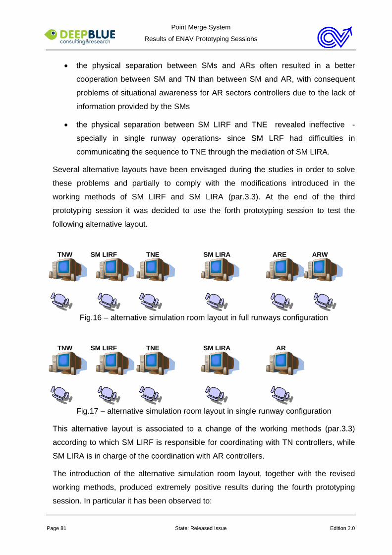
Point Merge System
Results of ENAV Prototyping Sessions
Page 81 State: Released Issue Edition 2.0
• the physical separation between SMs and ARs often resulted in a better
cooperation between SM and TN than between SM and AR, with consequent
problems of situational awareness for AR sectors controllers due to the lack of
information provided by the SMs
• the physical separation between SM LIRF and TNE revealed ineffective -
specially in single runway operations- since SM LRF had difficulties in
communicating the sequence to TNE through the mediation of SM LIRA.
Several alternative layouts have been envisaged during the studies in order to solve
these problems and partially to comply with the modifications introduced in the
working methods of SM LIRF and SM LIRA (par.3.3). At the end of the third
prototyping session it was decided to use the forth prototyping session to test the
following alternative layout.
TNW SM LIRF TNE SM LIRA ARE ARW
Fig.16 – alternative simulation room layout in full runways configuration
TNW SM LIRF TNE SM LIRA AR
Fig.17 – alternative simulation room layout in single runway configuration
This alternative layout is associated to a change of the working methods (par.3.3)
according to which SM LIRF is responsible for coordinating with TN controllers, while
SM LIRA is in charge of the coordination with AR controllers.
The introduction of the alternative simulation room layout, together with the revised
working methods, produced extremely positive results during the fourth prototyping
session. In particular it has been observed to:
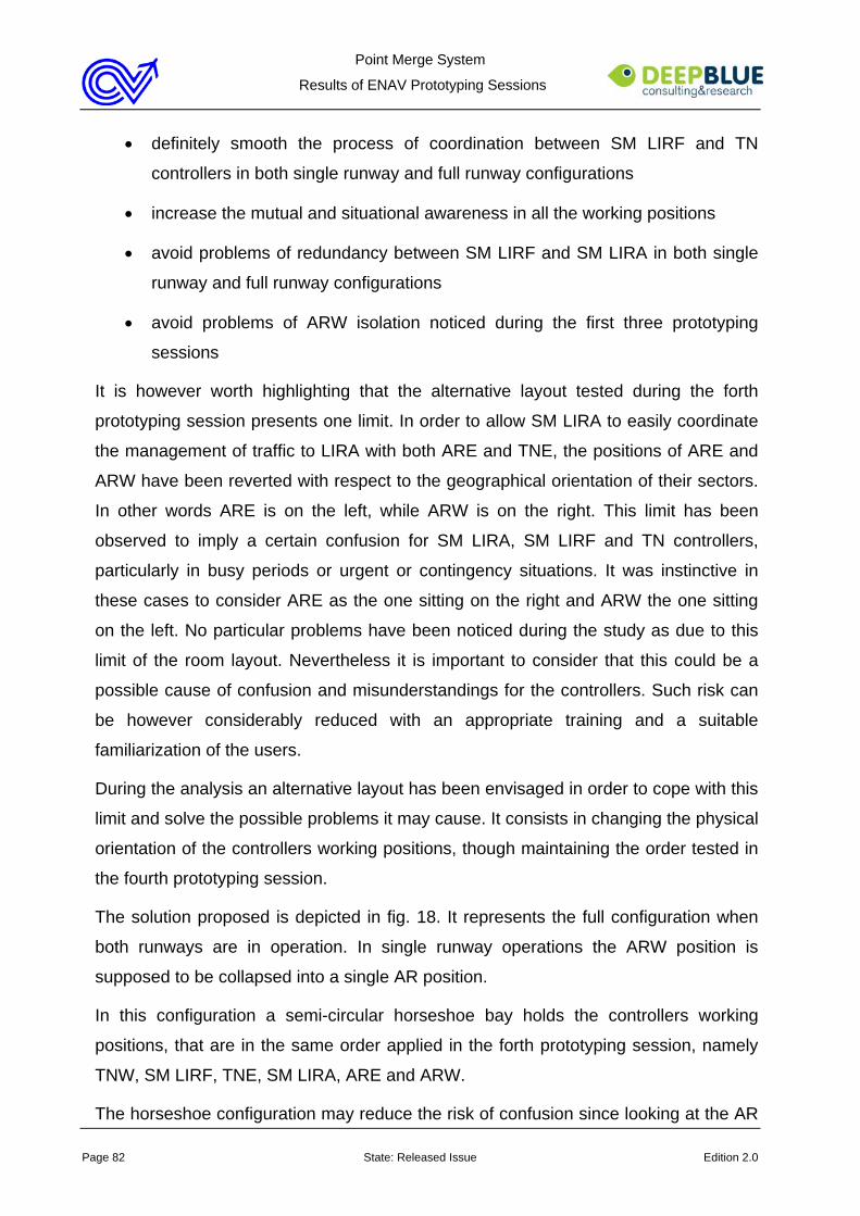
Point Merge System
Results of ENAV Prototyping Sessions
Page 82 State: Released Issue Edition 2.0
• definitely smooth the process of coordination between SM LIRF and TN
controllers in both single runway and full runway configurations
• increase the mutual and situational awareness in all the working positions
• avoid problems of redundancy between SM LIRF and SM LIRA in both single
runway and full runway configurations
• avoid problems of ARW isolation noticed during the first three prototyping
sessions
It is however worth highlighting that the alternative layout tested during the forth
prototyping session presents one limit. In order to allow SM LIRA to easily coordinate
the management of traffic to LIRA with both ARE and TNE, the positions of ARE and
ARW have been reverted with respect to the geographical orientation of their sectors.
In other words ARE is on the left, while ARW is on the right. This limit has been
observed to imply a certain confusion for SM LIRA, SM LIRF and TN controllers,
particularly in busy periods or urgent or contingency situations. It was instinctive in
these cases to consider ARE as the one sitting on the right and ARW the one sitting
on the left. No particular problems have been noticed during the study as due to this
limit of the room layout. Nevertheless it is important to consider that this could be a
possible cause of confusion and misunderstandings for the controllers. Such risk can
be however considerably reduced with an appropriate training and a suitable
familiarization of the users.
During the analysis an alternative layout has been envisaged in order to cope with this
limit and solve the possible problems it may cause. It consists in changing the physical
orientation of the controllers working positions, though maintaining the order tested in
the fourth prototyping session.
The solution proposed is depicted in fig. 18. It represents the full configuration when
both runways are in operation. In single runway operations the ARW position is
supposed to be collapsed into a single AR position.
In this configuration a semi-circular horseshoe bay holds the controllers working
positions, that are in the same order applied in the forth prototyping session, namely
TNW, SM LIRF, TNE, SM LIRA, ARE and ARW.
The horseshoe configuration may reduce the risk of confusion since looking at the AR
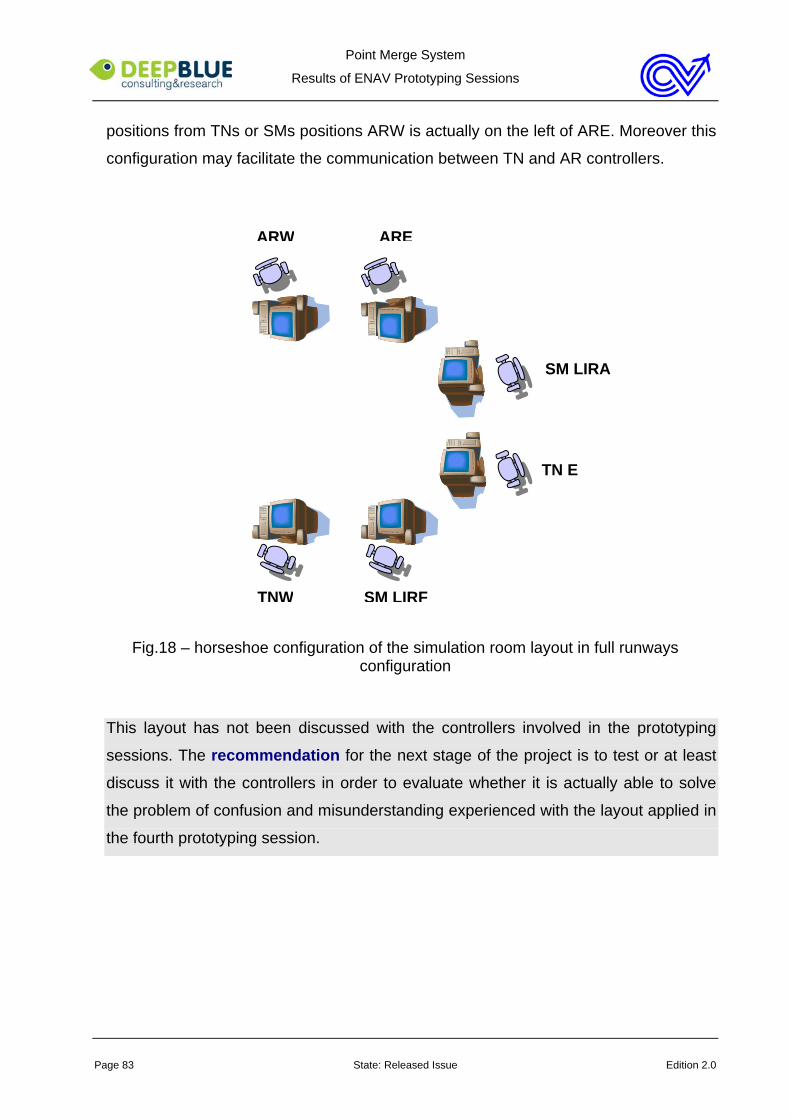
Point Merge System
Results of ENAV Prototyping Sessions
Page 83 State: Released Issue Edition 2.0
positions from TNs or SMs positions ARW is actually on the left of ARE. Moreover this
configuration may facilitate the communication between TN and AR controllers.
Fig.18 – horseshoe configuration of the simulation room layout in full runways configuration
This layout has not been discussed with the controllers involved in the prototyping
sessions. The recommendation for the next stage of the project is to test or at least
discuss it with the controllers in order to evaluate whether it is actually able to solve
the problem of confusion and misunderstanding experienced with the layout applied in
the fourth prototyping session.
ARW
SM LIRA
SM LIRFTNW
ARE
TN E
Point Merge System
Results of ENAV Prototyping Sessions
Page 84 State: Released Issue Edition 2.0
3.6 Appropriateness of Human Machine Interaction
The system used during the prototyping sessions revealed almost effective for the
application of the PMS method. The absence of STCA and MSP was not perceived as
problematic.
A few defects have however been detected during the studies. They have been
divided in two classes concerning:
• the lack of some information considered necessary for the effective application
of the method and the smooth management of the arrival traffic
• the lack of some functionalities of display setting that are considered important
to allow the controllers to properly apply the method.
Details are provided hereafter.
3.6.1 Defects of missing information
Problems of missing information concern:
• the assigned speed
• the assigned runway
• the arrival sequence
The lack of each of these pieces of information implied inquiries by the controllers and
brought to ineffective behaviours.
Lack of information about the assigned speed
The label provides only information about the actual speed. The controllers’ opinion is
that the assigned speed is also important to manage the arrival traffic. The lack of this
information implies problems of situational awareness and induces the controllers to
often check the assigned speed with the pilots.
This problem could be easily solved just adding this information in the label and
allowing the controllers to update it according to the instructions provided.
Lack of information about the assigned runway
One of the basic principles of the PMS method is the association between aircraft
Point Merge System
Results of ENAV Prototyping Sessions
Page 85 State: Released Issue Edition 2.0
bearing, triangles and runways. According to this principle the direction from which the
aircraft comes determines the triangle in which it is inserted and the triangle in turn
determines the runway. This principle is quite straightforward and effective.
Problems of situational awareness have been noticed during the study when this
principle has not been respected due to runway balancing or requests of runway
change. In these cases in fact the bearing is no more a sufficient indicator of the
runway in which the aircraft will land.
During the studies the controllers have often been observed to use the speed vector
to mark the aircraft not respecting the principle above. This behaviour was useful for
the controllers. Nevertheless it is not effective. It presents in fact two main problems:
• it marks in the same way different kinds of traffic, as for instance traffic that
have been rerouted from the other triangle to the one managed and traffic
managed within the West triangle but is supposed to land on runway 16L/34R
• it is local, in the sense that each controller uses the speed vector in his own
radar screen. A tool mediating the information exchange among the controllers
would be much more effective.
This problem could be easily solved providing the controllers with information about
the assigned runway in the label and allowing the SM LIRF to modify this information
as soon as a runway change has been arranged.
Lack of information about the sequence
In general with full runways configuration the sequence is quite visible on the radar
screen, but for cases in which a traffic landing on the east runway flies the West
triangle.
Much more difficult is the visualisation of the sequence in case of single runway
operations. In this case SM LIRF and SM LIRA have often been observed to check
the sequence each other and with their respective TNW and TNE sector controllers in
order to ensure to be all aware of it and share the same traffic picture. In addition the
TN sectors controllers tended to use the speed vector to mark the aircraft in the other
triangle after which their aircraft should have been turned to the merge point. This
further use of the speed vector, besides those already discussed, contributes to
Point Merge System
Results of ENAV Prototyping Sessions
Page 86 State: Released Issue Edition 2.0
consider this strategy not effective.
The problem could be solved providing SM LIRF with the possibility to insert the
sequence into the system and to provide TN sectors controllers with indications about
this sequence. Two suggestions have been collected:
• providing the landing number in the label
• graphically show the sequence in the radar screen linking the aircraft according
to the sequence order
Both solutions present possible defects in terms of usability:
• the first one implies a continuous update of the landing number as soon as the
sequence proceeds, that can be fastidious and distracting for the controllers
• the second one may reveal intrusive in the radar screen and potentially
distracting for the controllers
The recommendation is to use the following stage of the project to verify this need
and eventually complete the collection of the requirements. A dedicated design and
evaluation session will be then necessary to define the best way to provide this
information.
3.6.2 Limits of display settings
Display settings have been noticed to play a key role for the effective application of
PMS. The visualisation of triangles, sequencing legs and distance rings is an
important means to externalise the controllers’ knowledge and support the monitoring
of the traffic. Two interesting issues have been noticed during the study with respect
to the way the MSP geography was represented on the radar screen. They concern:
• the display ranges available by default in the HMI
• the way the settings have to be manually changed in case of switch from PMS
to conventional arrival traffic management or vice versa
In both cases the current system does not seem adequate to support the effective use
of the method.
Point Merge System
Results of ENAV Prototyping Sessions
Page 87 State: Released Issue Edition 2.0
Display ranges available by default in the HMI
The system currently in use at Rome ACC provides some display default ranges that
the controllers can easily set just clicking on a label.
Several cases have been observed during the study in which the use of these ranges
or of a different range manually set brought the controllers to ineffective behaviours in
terms of traffic management and respect of their own roles. Examples of typical
effects that a wrong setting (too large, too narrow or inappropriately centred) may
contribute to produce are:
• redundancy with other controllers,
• underestimations of potentially critical situations,
• ineffective use of runway capacity
• not respect of the separation at touchdown requested by the tower and
consequent go around.
This problem could be solved redesigning the provision of default display ranges in
the light of their possible usage.
The solution envisaged during the study is based on the idea of providing the
controllers with suggestions about the correct settings to be used in each working
positions, in terms not only of range but also of centre. The settings available in the
radar screens of the TMA sectors are then 7, labelled respectively TNW, TNE, ARW,
ARE, SM LIRF, SM LIRA and AR (to be used in single runway operations). Each of
these label automatically sets the radar screen on the basis of the range and centre
considered appropriated for the associated working position. The controllers remain
free to change these settings manually, but in doing this activity they are conscious to
be no more using the setting considered optimal for that position.
In each TMA controller working position all the settings are available. This has the
twofold purpose of increasing:
• the situational awareness, since it allows the controllers to have a quick look to
the situation of the colleagues
• the resilience of the system, since in case of contingency each working position
can be used to display the every TMA sectors.

Point Merge System
Results of ENAV Prototyping Sessions
Page 88 State: Released Issue Edition 2.0
Manual change of the ATS geography during the transition
The modification of the ATS geography represented on the radar screens is a key
activity during the transition from PMS to conventional arrival traffic management and
vice versa. The experience of the fourth prototyping session highlighted that problems
of situational awareness and effectiveness of the traffic management may occur in
case the visualisation on the radar screen has not been updated appropriately.
A function is necessary allowing the controllers to quickly switch from PMS geography
to conventional ATS geography of arrival traffic management and vice versa as soon
as the transition is carried out.
Point Merge System
Results of ENAV Prototyping Sessions
Page 89 State: Released Issue Edition 2.0
Chapter 4 Conclusions and Lesson Learnt
The prototyping sessions produced positive results on the users’ acceptability and
domain suitability of applying the PMS technique in the operational environment of
Rome TMA.
The controllers involved in the study found the method comfortable, safe, accurate
and easy to learn and to apply. In very short time they became familiar with it and able
to apply it properly and effectively, even under high traffic load and in case of non
nominal events. They considered the new technique suitable to and easy to accept in
Rome TMA sectors, perceiving it as the evolution of the current method based on
radar vectoring as result of the introduction of the PRNAV capability.
In their opinion the adoption of this method is likely to yield the following advantages:
• standardisation of the controllers performances, thus implying a standard high
quality of the traffic management, less conditioned by personal skills and one’s
own tolerance of traffic density and complexity
• improved teamwork, since the standardisation of the work allows to predict and
anticipate the colleague’s behaviour, expectations and needs
• general reduction of controller cognitive workload in all TMA sectors, since the
Point Merge System
Results of ENAV Prototyping Sessions
Page 90 State: Released Issue Edition 2.0
standardised way of managing the arrival traffic simplifies the work and
reduces the need for problem solving, continuous monitoring and R/T
communication
• general high level of job satisfaction in the controllers, since the less creativity
required for the arrival traffic management is counterbalanced by evident
positive results in terms of spacing and runway capacity usage.
They also highlighted some drawbacks of the PMS technique, among which the
following ones are worth to be reported:
• loss of flexibility with respect to the current open loop vectors technique
• conditioned applicability in certain circumstances (i.e. bad weather conditions
impairing the use of both triangles and point merges), thus entailing the need
for radar vectoring to continue to be applied
• concurrent application of radar vectoring and PMS method in case of traffic not
100% PRNAV equipped
• possible impact on the controllers workload in E-TMA sectors
They tended however to accept these limits as tolerable side effects of the PMS
technique. They were conscious of these drawbacks, but did not consider them as
limitative as to impair the acceptability of the technique itself and/or its effectiveness.
On the contrary they appreciated the possibility to continue using the method even
partially or in non conventional ways in the cases in which it was instead expected not
to be usable at all. The management of non nominal events (i.e. bad weather, mixed
equipped traffic samples and transition from PMS to radar vectoring and vice versa)
confirmed these results.
Positive results have been also achieved with respect to the incremental and iterative
validation approach adopted in this phase of the project. The execution of small
sessions of assessment, besides allowing to test PMS in different operational
scenarios of Rome TMA, confirmed to be extremely fruitful also from the validation
point of view. Each session was a means to scratch hypotheses, preliminary results
and possible redesign suggestions to be further checked, implemented and/or
validated in the following ones. Each report was in this respect a working document
intended to compare the result of the study with the ones of the previous sessions,
Point Merge System
Results of ENAV Prototyping Sessions
Page 91 State: Released Issue Edition 2.0
consolidate the results produced so far and provide recommendations and way
forward for the following sessions and/or phases of the project.
In addition to the recommendation for the next stage of the project also some lessons
learnt have been elicited. They are presented hereafter as a proof of the effectiveness
of the approach adopted and as guidelines for future projects with a similar
organisation.
Lessons Learnt
• Though the iterative and incremental validation approach was effective, the
schedule of the prototyping sessions revealed quite narrowed to allow to full
benefit by its possible benefits. The time between one session and the
following one was just enough for the analysis and the provision of the report.
Some more time would have been necessary to properly share the results
within the project team and organise together the following session.
• The original idea of involving four different teams of controllers revealed
ineffective during the study. In principle it is a means to enlarge the exposure to
the PMS method and to collect a rich set of results. In reality instead the
experience gathered in the second prototyping session highlighted an important
side effect of this choice. The short duration of each prototyping session did not
reveal adequate to allow the novices to capitalise the knowledge collected in
the previous session and provide additional results. Their contribution mainly
consisted in a checking and confirming the results of the previous session. A
trade-off was evident between using a unique team or different teams. The first
opinion was expected to produce a rich set of results, but presented the risk to
introduce some biased in the results due to the limited number of controllers
involved. The second opinion was expected to produce more objective results,
thanks to the larger exposure, but however these results were expected to be
repetitive and less detailed. In this trade off it was considered preferable to
involve a unique team. This choice was considered more effective as it would
have allowed to get a richer set of results concerning the use of PMS in Rome
TMA. On the basis of this decision the team involved in the first session has
been involved also in the third and fourth ones.
• The idea of involving some members of the project core team as controllers of

Point Merge System
Results of ENAV Prototyping Sessions
Page 92 State: Released Issue Edition 2.0
the simulation team revealed inadequate. The discrepancy of knowledge and
performances was evident particularly in the second prototyping session. It
produced negative results in terms of teamwork and active participation of the
novices to the prototyping session. The decision to keep the team of the first
session involved also in the third and fourth ones (bullet point above) allowed to
overcome the problem since the controllers’ performances and knowledge
tended to harmonise and be homogenous.