Embed Size (px)
Citation preview

Policy No.: SS 7 Page 1 of 10
NEW CASTLE COUNTY DEPARTMENT OF SPECIAL SERVICES
SEWER DESIGN POLICY
Policy No.: SS 7 Subject: Sewer Design, Capacity and Review Standards for Land
Development Applications Date of Publication: May 1, 2012 Effective Date: May 1, 2012 Supersedes Policy No.: All previous policies on the Subject Supplements Policy No.: N/A ______________________________________________________________________________
Objective: To establish standard practices and procedures for sanitary sewer design and design review, as they pertain to the design and review of proposed land development projects.
Legal Authority: Chapter 38, Sec. 38.02.005 of the New Castle County Code ("Code") provides for the Department of Special Services (“Department”) to establish standards for construction for sanitary sewer. In this regard, the following guidelines are hereby adopted:
A) Sanitary Sewer Design Review
1) Sanitary sewer construction drawings and documents relating to the design as
described within this policy shall be reviewed by the Department in accordance with this policy. This design review process applies to gravity sewer lines, pump stations, force main and right-of-way plans.
2) The Department will review sanitary sewer construction drawings and related
documents in the order in which they are submitted. 3) The Department will provide comments on sanitary sewer construction drawings
and related documents submitted within twenty (20) business days of the submission.
B) Sanitary Sewer Design Checklist and Policy Exceptions
1) The Design Professional shall include the latest version of the Sanitary Sewer Design Checklist when submitting private land development sanitary sewer construction plans for the Department’s review and approval. All items on the

Policy No.: SS 7 Page 2 of 10
checklist must be clearly addressed or the submission will be rejected and an additional review fee may be required for re-submission.
2) Any exception to these requirements must be clearly identified by the Design
Professional when plans are submitted for Department review, along with technical justification as to why the exception has been requested. At a minimum, justification shall include alternatives investigated by the Design Professional and benefits to the County. The Department will review the information provided and/or require additional information. The Department shall be the sole judge in all circumstances in determining whether the requested exception is acceptable.
3) Exceptions to these design standards and practices shall be identified as early in
the design practice as possible. Exceptions identified during the Record Stage of the land development process may be rejected without further consideration.
4) In the event an exception is granted for good cause, the Department shall issue a
written memorandum outlining the circumstance and rational basis for such an exception, signed by the Division Manager of Special Services, Engineering and Environmental Services Division.
5) The County will consider all exceptions on a case by case basis.
C) Survey Requirements
1) The Design Professional shall provide precise and accurate survey data on construction plans that adequately describe existing site conditions.
2) The Design Professional shall provide all elevation datum in accordance with
NAVD 88 for all major land development projects.
a) NGVD 1929 is acceptable for minor land development projects; however, a conversion to NAVD 88 shall be provided on the plans.
3) The Design Professional shall provide Delaware State plane for horizontal control
and location of all manholes and at least one established, permanent benchmark for all major land development projects.
D) Sanitary Sewer Construction Details
1) The Design Professional shall include the latest revision of New Castle County
Standard Construction Details, as provided in the New Castle County Specification Standards for Construction.
2) If a method of construction is proposed in which a detail is not provided, the Design Professional shall follow the exception process as generally described in Section B above and provide the County with necessary information.
E) Proposed Sewer Flow, Pipe Grade and Pipe Size
Policy No.: SS 7 Page 3 of 10
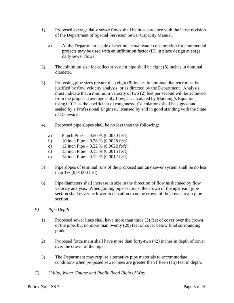
1) Proposed average daily sewer flows shall be in accordance with the latest revision
of the Department of Special Services’ Sewer Capacity Manual.
a) At the Department’s sole discretion, actual water consumption for commercial projects may be used with an infiltration factor (IF) in place design average daily sewer flows.
2) The minimum size for collector system pipe shall be eight (8) inches in nominal
diameter.
3) Proposing pipe sizes greater than eight (8) inches in nominal diameter must be justified by flow velocity analysis, or as directed by the Department. Analysis must indicate that a minimum velocity of two (2) feet per second will be achieved from the proposed average daily flow, as calculated by Manning’s Equation, using 0.013 as the coefficient of roughness. Calculations shall be signed and sealed by a Professional Engineer, licensed by and in good standing with the State of Delaware.
4) Proposed pipe slopes shall be no less than the following:
a) 8 inch Pipe – 0.50 % (0.0050 ft/ft) b) 10 inch Pipe – 0.28 % (0.0028 ft/ft) c) 12 inch Pipe – 0.22 % (0.0022 ft/ft) d) 15 inch Pipe – 0.15 % (0.0015 ft/ft) e) 18 inch Pipe – 0.12 % (0.0012 ft/ft)
5) Pipe slopes of terminal runs of the proposed sanitary sewer system shall be no less
than 1% (0.01000 ft/ft).
6) Pipe diameters shall increase in size in the direction of flow as dictated by flow velocity analysis. When joining pipe sections, the crown of the upstream pipe section shall never be lower in elevation than the crown of the downstream pipe section.
F) Pipe Depth
1) Proposed sewer lines shall have more than three (3) feet of cover over the crown
of the pipe, but no more than twenty (20) feet of cover below final surrounding grade.
2) Proposed force main shall have more than forty-two (42) inches in depth of cover
over the crown of the pipe.
3) The Department may require alternative pipe materials to accommodate conditions when proposed sewer lines are greater than fifteen (15) feet in depth.
G) Utility, Water Course and Public Road Right of Way

Policy No.: SS 7 Page 4 of 10
1) Crossings
a) All utilities and water courses within twenty (20) feet of the proposed sewer
system must be clearly depicted on the sanitary sewer plan and profile views. This includes overhead utilities and poles.
b) A casing pipe is generally required by the Delaware Department of
Transportation (DELDOT) when crossing a public road right of way. Crossings shall be orientated as close to perpendicular with the right of way as possible. The casing pipe shall be steel, of adequate thickness and a minimum of twenty-four (24) inches in internal diameter.
c) Separation, reinforcing, pipe specifications and other provisions for utility and
water course crossings shall be provided in accordance with the Recommended Standards for Wastewater Utilities, 2004 Edition, Section 36 entitled “Sewers in Relation to Streams” and/or Section 38 entitled “Protection of Water Supplies.”
d) Provisions for the utility or water course crossing shall extend a minimum of
ten (10) feet beyond the point of crossing, but in no way shall be less than twenty (20) feet in total length. Provisions may include but are not limited to use of pressure rated pipe, casing pipe and/or concrete encasement.
e) Final requirements of the crossing shall be determined by the Department
during design review. 2) Horizontal Separation
a) The preferred horizontal separation between the proposed sanitary sewer
infrastructure and any existing or proposed utility infrastructure shall be no less than ten (10) feet. A horizontal separation of greater than ten (10) feet may be required by the Department due to factors that include depth and/or size of the sanitary sewer infrastructure or utility, access or other site restrictions, or other considerations as determined by the Department.
H) Off-Road Sewer and Easements
1) Proposed public sanitary sewer infrastructure located outside of a public right-of-way shall be located within the limits of a sanitary sewer easement. Easements shall be established in accordance with the latest guidelines set forth by the Department’s Project Management Section via easement agreement, land development plan or other legally recorded document.
2) Easements shall be clearly depicted on plans, including proposed dimensions, and
benefactor of the easement (New Castle County or private entity).

Policy No.: SS 7 Page 5 of 10
3) Sanitary sewer easements shall be at least forty (40) feet in width and shall run continuous with the proposed sewer infrastructure until it enters into the public right-of-way or existing, legally established easement.
4) Easements for sanitary sewer lines that abut a building shall be no less than sixty
(60) feet in width if the sanitary sewer line is greater than ten (10) feet deep measured from ground surface.
5) The sanitary sewer shall be centered in the proposed sanitary sewer easement.
6) Proposed sanitary sewer lines shall not be located in generic utility easements,
stormwater easements or landscape buffers.
7) No permanent structure shall be located within the sanitary sewer easement. Permanent structures include but are not limited to stormwater management infrastructure and other utilities, and landscaping features such as trees, shrubs, fences and signs.
a) The Department may allow existing structures to be located within the limits
of the sanitary sewer easement, as long as it can be determined that no acceptable alternate route is available, the structure was constructed and/or installed prior to the construction of the proposed sanitary sewer line, and the structure will not restrict access for continued operation and maintenance of the proposed sanitary sewer line. In the case of a fence, the Department may require a gate be installed such that access to the proposed sanitary sewer line is provided.
8) Off-road sanitary sewer lines shall include a “turf trail”, as detailed in New Castle
County Standard Details.
9) Significant impact to existing landscaping shall be clearly noted on the plans.
10) More detailed information concerning topography or other area attribute may be requested by the Department to provide a more complete picture of existing and proposed conditions when off-road sewer is proposed.
I) Pipe Materials
1) Pipe and fitting materials for the proposed sanitary sewer system shall conform to the latest version of the New Castle County Standard Specifications for Construction.
2) The Department may require a specific material, pipe class and/or interior or
exterior coating or encasement where, in the Department’s opinion, conditions warrant. Conditions may include but are limited to industrial use, projects where excessive velocity is anticipated, and/or poor subsurface conditions.
Policy No.: SS 7 Page 6 of 10
a) Alternative pipe materials may include but are not limited to high density polyethylene (HDPE), vitrified clay pipe (VCP), centrifugally cast fiberglass reinforced polymer mortar (CCFRPM) pipe, reinforced concrete pipe (RCP) and/or ductile iron pipe (DIP).
b) Alternative pipe coatings and/or linings may include but are not limited to
epoxy lining, cured in place pipe lining (CIPPL), concrete lining, PVC (for RCP) lining, and/or bituminous coating.
J) Sanitary Sewer Manholes
1) Manholes shall conform to the New Castle County Standard Specifications for Construction.
2) Manholes shall be located to facilitate on-going maintenance and operation of the
sewer system.
3) Manholes shall not be located in gutters, swales or low spots in roads.
4) Manholes shall be placed at all locations where the sanitary sewer changes lateral direction, pipe size, pipe slope, and no more than three-hundred (300) linear feet apart.
5) Manholes shall include a minimum bench width of eighteen (18) inches on either
side of the channel.
6) Sanitary sewer manhole frame and cover elevations shall be verified to match the final road elevation prior to final paving. Adjustment risers of any type in order to match the final paving elevation are not acceptable.
7) Drop manholes shall not be used without authorization. If approved, drop
manholes shall be designed per the New Castle County Standard Details. Outside drops are not acceptable.
8) Lamp holes are not acceptable. 9) The top of manholes located in unpaved areas shall be at an elevation six (6)
inches above surrounding final grade or one (1) foot above the one-hundred (100) year flood plain elevation, if applicable. The top of manholes located in unpaved areas shall not be greater than four (4) feet above final grade. A berm shall surround elevated manhole rims, as shown in the New Castle County Standard Details.
10) The Department may require a specific material and/or interior or exterior coating
where, in the Department’s opinion, conditions warrant. Conditions may include but are limited to industrial use, where hydrogen sulfide gases and/or high velocities are anticipated, and/or poor subsurface conditions.

Policy No.: SS 7 Page 7 of 10
a) Alternative manhole materials and coatings may include but are not limited to HDPE, CCFRPM, polymer concrete, epoxy coatings/linings, PVC and/or bituminous coatings.
K) Sanitary Sewer Laterals and Building Connections.
1) Each proposed lot shall be serviced by an individual sanitary sewer lateral connection to the public sanitary sewer system. If the proposed use of the building includes food preparation such that a grease interceptor is required, two (2) service laterals are acceptable.
2) Requirements of the sanitary sewer lateral located outside the public right-of-way
or public sanitary sewer easement shall be in accordance with the New Castle County Code, Chapter 6, Article 7, Section 1 (Adoption of the International Plumbing Code).
3) The sanitary sewer lateral located within the public right-of-way or public
sanitary sewer easement shall not be less than six (6) inches in internal diameter.
4) The minimum slope for the section of the sanitary sewer lateral located within the public right-of-way or public sanitary sewer easement shall be 2% (0.0200 ft/ft).
5) No sanitary sewer laterals shall be allowed to connect directly to sanitary sewer
pipe having an internal diameter greater than fifteen (15) inches without approval of the Department.
6) The minimum vertical distance between the invert of the sanitary sewer lateral
connection at the sanitary sewer main and the lowest sewered floor of the house or building shall be five (5) feet.
7) The minimum vertical distance required in section I(6) is waived if the
determining floor is at least twelve (12) inches higher in elevation than the manhole rim elevation immediately upstream from the lateral connection.
8) If the provisions of I(6) and I(7) cannot be met, a backflow valve must be
provided. The backflow valve shall conform to New Castle County Code, Chapter 6, Article 7, Section 1 (Adoption of the International Plumbing Code).
9) The requirements of this section are minimums not determined by the hydraulic
loading of the sanitary sewer in the street.
L) Grease Interceptors
1) All proposed land development plans that include a Commercial Food Establishment (CFE) shall include a grease interceptor in accordance with design the requirements herein.
Policy No.: SS 7 Page 8 of 10
a) Location should be accessible for maintenance. If located within a vehicular traffic area, grease interceptor shall be H-20 loaded.
b) Sizing calculations performed in accordance with Environmental Protection
Agency (EPA) 2 Model, “Recommended Grease Trap Sizing Formula,” or latest revision. Minimum storage capacity of grease interceptors shall be 1,000 gallons.
c) Only sanitary sewer laden with fats, oils and grease from food preparation
appliances and fixtures shall be directed into a grease interceptor. d) Grease interceptors must be constructed of either pre-cast concrete or
fiberglass with an internal baffle, in accordance with New Castle County Code Chapter 6, Buildings and Structures, Article 7 Plumbing Code, Chapter 10 Traps, Interceptors and Separators, §P1003.3.4 Grease Traps.
M) Pump Stations
1) All proposed pump stations shall be sized to handle a minimum average daily flow of 45,000 gallons per day, or the equivalent flow of one hundred fifty (150) single family dwelling units.
a) If a proposed subdivision does not meet the minimum flow requirement, the
land developer shall follow the exception process described herein. The developer shall provide at a minimum build-out flow projections and mapping for the region that may be serviced by the proposed pump station, including but not limited to topographic features, a count of existing lots currently serviced by on-site septic systems, and development potential of undeveloped property. If the study is accepted by the Department, feasibility of the results of the engineering study shall be demonstrated at each land development phase. The developer further recognizes that final approval of the sanitary sewer construction plans is dependent on incorporating results from the build-out analysis into the proposed sanitary sewer system.
2) Pump stations shall be designed in accordance with the latest version of the Pump
Station Design Guidelines, provided in Appendix A, by a Professional Engineer, licensed by and in good standing with the State of Delaware.
N) Submain systems.
1) Nothing in this policy shall prohibit the installation of a submain system in any dwelling, provided that the submain is pumped by equipment owned by the property owner up into the regular house system by a pumping system in accordance with the most recent version of the New Castle County plumbing code.
O) Data required by State of Delaware.

Policy No.: SS 7 Page 9 of 10
a) Additional information may be required by State of Delaware regulatory agencies that are responsible for granting various permits for the construction of sanitary sewer systems. The Department will communicate those requirements whenever possible, but the Design Professional is solely responsible for knowing and understanding those requirements and providing the necessary information to the appropriate agency.
P) Recommended Standards for Wastewater Facilities
1) If not expressly described herein, the Department will reference the latest version of the Recommended Standards for Wastewater Facilities for guidance in reviewing a proposed sanitary sewer system.
Q) Private Sanitary Sewer Systems
1) Sanitary sewer systems and pump stations that are proposed for private ownership and maintenance shall conform to these design requirements as if the proposed system were to be owned and maintained by New Castle County.
R) Regional Sanitary Sewer Systems
1) The Design Professional is required to assess any unsewered area for possible inclusion into the proposed sanitary sewer system. The Department, in their sole discretion, may require the proposed sanitary sewer system to include features necessary to facilitate the expansion of the proposed sanitary sewer system area into a “regional” sanitary sewer service area. Features may include but are not limited to larger pipe sizes or pump station infrastructure, increased depth of sanitary sewer manholes or wet wells, pipe stubs or sanitary sewer alignment. The Design Professional is expected to cooperate to the fullest extent with the Department and other developers as necessary to promote an efficient sanitary sewer system.

Policy No.: SS 7 Page 10 of 10
Appendix A
New Castle County Pump Station Design Guidelines
GENERAL PROVISIONS 1 These guidelines are for reference only. Final approval of pumping station design is solely based on New Castle County review and approval.
GENERAL PROVISIONS
PART 1 GENERAL 1.01 SCOPE OF WORK
A) Furnish and provide all labor, equipment and materials to design, furnish and install a complete and fully functional pump station as specified herein.
B) Requirements found in this division are common to all New Castle County
pump stations. Refer to the subsequent divisions for specific requirements for suction lift and submersible pump stations, emergency generators and telemetry system.
C) If conditions are appropriate, New Castle County will require that a suction
lift pump station be designed for and furnished.
D) Sub-grade, pre-fabricated flooded suction pump stations are not acceptable to New Castle County.
E) A pump station that incorporates the use of grinder pump(s) is not acceptable to New Castle County.
F) These guidelines include drawings for pump stations and force main. The
drawings shall be used with these guidelines to interpret the New Castle County standard. The drawings are not to scale, and shall be used for information only.
G) Due to changing technology and practices, these guidelines are for reference
only. New Castle County reserves the right to update these guidelines without notification. All equipment supplied and labor performed is subject to individual review and approval by New Castle County.
1.02 SUBMITTALS
A) Submit completely scaled and dimensioned drawings in plan and cross section as required to provide a complete description of the entire system. Drawings shall be certified for construction by a Professional Engineer and approved by New Castle County.
B) Drawings shall include the following at a minimum:
1) Site, elevation and plan views that completely describe the pump station 2) Force main from the pump station to discharge point in plan and elevation 3) Equipment layout with specific dimensions and locations 4) Location of electrical connections and characteristics 5) Wiring diagrams for all equipment
GENERAL PROVISIONS 2 These guidelines are for reference only. Final approval of pumping station design is solely based on New Castle County review and approval.
6) Wiring diagrams for motor and level controllers 7) Utility requirements (type, size and location(s)) 8) Supports and anchor bolt layout 9) Mounting requirements and clearances 10) Assembly views and materials of construction of all equipment 11) Diameter of shafting 12) Dimensions and rated horsepower of all motors 13) Gear and bearing ratings 14) Service factors and weights 15) Equipment sizing calculations
C) After the drawings are approved, the Contractor shall submit equipment
dimensions and construction, performance data including pump curves; equipment capacities, characteristics and limitations; materials of construction and finishes to New Castle County for review and approval. No equipment shall be installed prior to approval by New Castle County. New Castle County shall be the sole and final judge of the acceptability of materials and equipment.
D) Indicate installation requirements and special procedures as recommended by
the manufacturer. Provide equipment preparation and start-up procedures. E) Submit copies of factory run pump performance tests for pump size and type
selected, prior to pump delivery. F) Submit engineering calculations supporting equipment and material selected.
Calculations for the pump station and force main shall be submitted as described herein.
1.03 ENGINEERING CALCULATIONS
A) Calculations must include detailed pump station plans that clearly depict the proposed pump station, sanitary sewer, number of houses to be serviced by the pump station and force main up to the discharge point. Static head (pump off elevation to discharge point), lengths of pipe (force main and pump station) and approximate fittings must be clearly identified.
B) Both the average and peak hourly sewage flows must be determined. Industry
standards should be used in calculating the average sewage flows, which are determined from type of buildings or area that the pump station will service. The peak flow shall be determined by multiplying the average flow by 4.
The peak flow shall be used to determine the size of the pumps.
C) The pump size and requirements shall be determined from a pipe friction loss
analysis of the pump station piping and force main up to the discharge point. It is preferred that the Hazen-Williams method be used to calculate pipe
GENERAL PROVISIONS 3 These guidelines are for reference only. Final approval of pumping station design is solely based on New Castle County review and approval.
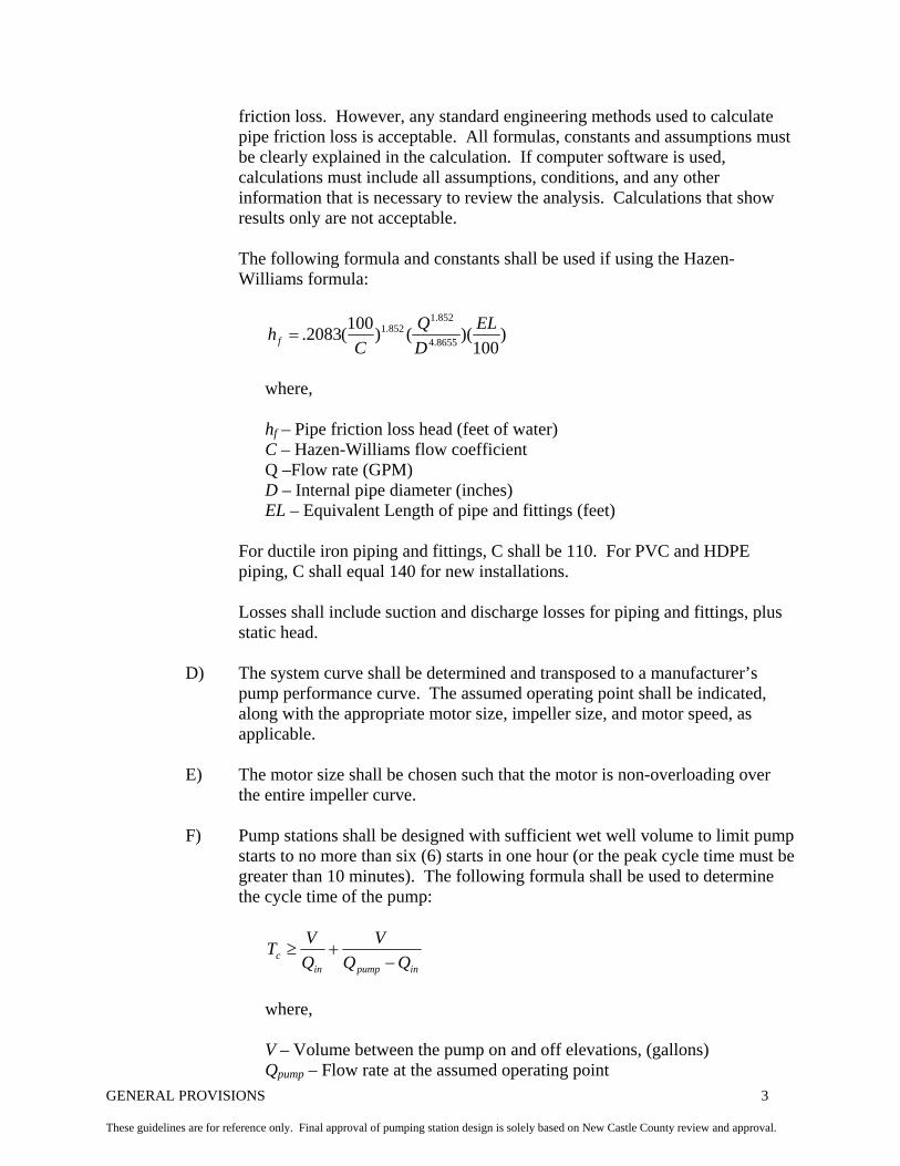
friction loss. However, any standard engineering methods used to calculate pipe friction loss is acceptable. All formulas, constants and assumptions must be clearly explained in the calculation. If computer software is used, calculations must include all assumptions, conditions, and any other information that is necessary to review the analysis. Calculations that show results only are not acceptable.
The following formula and constants shall be used if using the Hazen-Williams formula:
)100
)(()100(2083. 8655.4
852.1852.1 EL
DQ
Chf =
where,
hf – Pipe friction loss head (feet of water) C – Hazen-Williams flow coefficient Q –Flow rate (GPM) D – Internal pipe diameter (inches) EL – Equivalent Length of pipe and fittings (feet)
For ductile iron piping and fittings, C shall be 110. For PVC and HDPE piping, C shall equal 140 for new installations.
Losses shall include suction and discharge losses for piping and fittings, plus static head.
D) The system curve shall be determined and transposed to a manufacturer’s
pump performance curve. The assumed operating point shall be indicated, along with the appropriate motor size, impeller size, and motor speed, as applicable.
E) The motor size shall be chosen such that the motor is non-overloading over
the entire impeller curve.
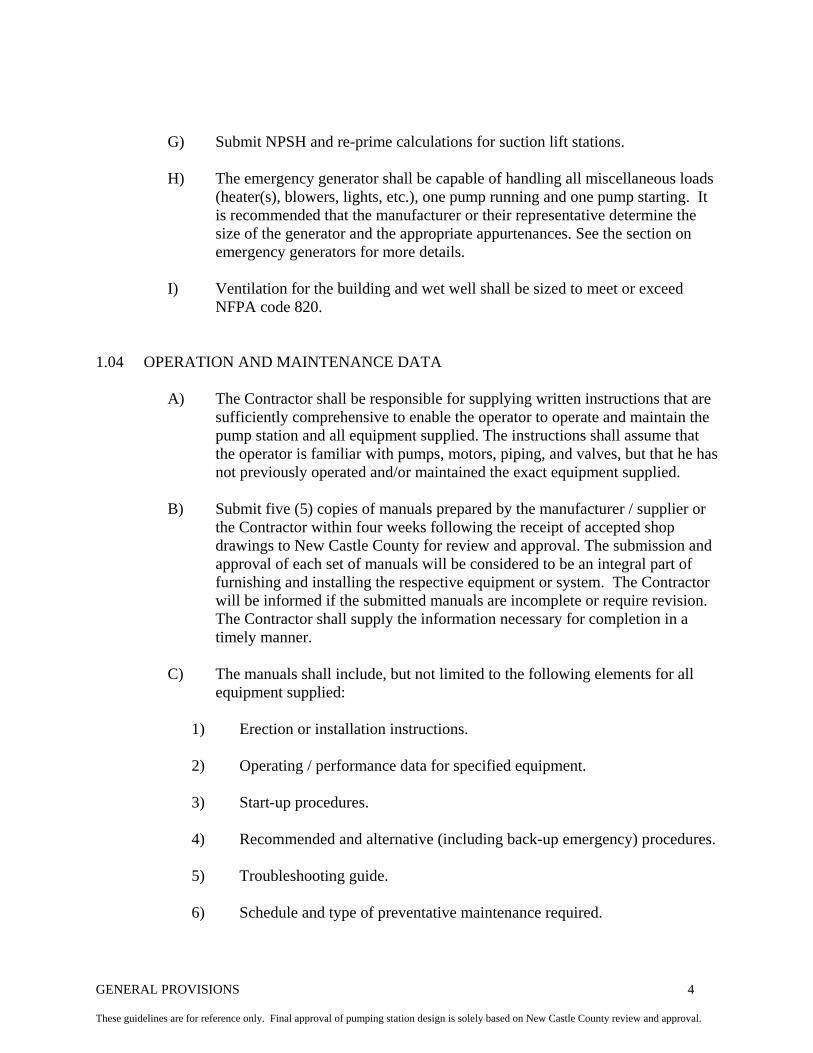
F) Pump stations shall be designed with sufficient wet well volume to limit pump starts to no more than six (6) starts in one hour (or the peak cycle time must be greater than 10 minutes). The following formula shall be used to determine the cycle time of the pump:
inpumpinc QQ
VQVT
−+≥
where,
V – Volume between the pump on and off elevations, (gallons) Qpump – Flow rate at the assumed operating point
GENERAL PROVISIONS 4 These guidelines are for reference only. Final approval of pumping station design is solely based on New Castle County review and approval.
G) Submit NPSH and re-prime calculations for suction lift stations.
H) The emergency generator shall be capable of handling all miscellaneous loads (heater(s), blowers, lights, etc.), one pump running and one pump starting. It is recommended that the manufacturer or their representative determine the size of the generator and the appropriate appurtenances. See the section on emergency generators for more details.
I) Ventilation for the building and wet well shall be sized to meet or exceed
NFPA code 820. 1.04 OPERATION AND MAINTENANCE DATA
A) The Contractor shall be responsible for supplying written instructions that are sufficiently comprehensive to enable the operator to operate and maintain the pump station and all equipment supplied. The instructions shall assume that the operator is familiar with pumps, motors, piping, and valves, but that he has not previously operated and/or maintained the exact equipment supplied.
B) Submit five (5) copies of manuals prepared by the manufacturer / supplier or
the Contractor within four weeks following the receipt of accepted shop drawings to New Castle County for review and approval. The submission and approval of each set of manuals will be considered to be an integral part of furnishing and installing the respective equipment or system. The Contractor will be informed if the submitted manuals are incomplete or require revision. The Contractor shall supply the information necessary for completion in a timely manner.
C) The manuals shall include, but not limited to the following elements for all
equipment supplied:
1) Erection or installation instructions. 2) Operating / performance data for specified equipment. 3) Start-up procedures. 4) Recommended and alternative (including back-up emergency) procedures. 5) Troubleshooting guide. 6) Schedule and type of preventative maintenance required.
GENERAL PROVISIONS 5 These guidelines are for reference only. Final approval of pumping station design is solely based on New Castle County review and approval.
7) Replacement parts list and schedule of recommended spare parts to be stocked, complete with part number, inventory quantity and ordering information.
8) Detailed maintenance procedures. 9) Schedule of lubrication requirements. 10) Corrected and approved control and wiring diagrams. 11) Data sheet listing pertinent equipment or system information.
12) Addresses and telephone numbers of the nearest sales and service
representatives.
13) Manufacturer’s warranty on all equipment supplied.
B) Operation and maintenance instructions that are limited to a collection of component manufacturer literature without overall pump station instructions are not acceptable.
C) Operation and maintenance instructions shall be specific to the equipment
supplied in accordance with these guidelines. Instruction manuals applicable to many different configurations and pump stations, and which require the operator to selectively read portions of the instructions are not acceptable.
1.05 QUALITY ASSURANCE
A) Design and construct the pumps in accordance with standards of the Hydraulic Institute. The efficiency of the pumps, when operating under conditions of the specified capacities and heads shall be as near peak efficiency as practicable.
B) Obtain pumping equipment, motors, drives, pump controls and appurtenance
from a pump supplier whose responsibility is to ensure that the pumping equipment is properly coordinated and operated in accordance with these guidelines.
C) The Contractor shall acquire the services of the equipment manufacturer's
representative for testing, instruction, and correction of deficiencies.
D) The pumps, motors, and controls shall be given an operational test in accordance with the standards of the Hydraulic Institute. Recordings of the test shall substantiate the correct performance of the equipment at the design head, capacity, suction lift (if applicable), speed and horsepower as herein specified.
GENERAL PROVISIONS 6 These guidelines are for reference only. Final approval of pumping station design is solely based on New Castle County review and approval.
E) After the installation is complete, a qualified factory representative shall place the pump station in operation, conduct a complete function check, and make all necessary adjustments for regular service.
F) The Contractor is responsible to honor the manufacturer’s warranty on all
equipment for one (1) year from the date of acceptance by New Castle County. The Contractor shall provide a copy of all warranty documentation from the equipment manufacturer at the time of acceptance.
G) The Contractor shall provide a warranty against any defect or malfunction due
to workmanship in the equipment and accessories for a minimum period of one (1) year from the date of final acceptance by New Castle County, unless otherwise stated in the individual pump station sections. In the event a component fails or is proven defective during the guarantee period, the Contractor will provide a replacement part and installation without cost to New Castle County.
H) A written manufacturer’s warranty shall be supplied for all individual
components, and included in the Operation and Maintenance manual.
I) The Contractor is responsible for storing, delivering and handling all material, equipment and machinery in accordance with the manufacturer’s recommendations.
1.07 SCHEDULING AND COORDINATION
A) The Contractor shall schedule and attend a pre-construction meeting with New Castle County Department of Special Services. Parties that shall attend the meeting shall include a representative from the site contractor, the pump station contractor and New Castle County Department of Special Services. No work shall be performed on the pumping station prior to this pre-construction meeting.
B) The Contractor is responsible to coordinate the delivery and installation of all
equipment and materials. This includes, but is not limited to, all work completed by sub-contractors, utilities, manufacturer’s representatives, New Castle County inspections and other involved parties.
C) All work shall be performed under the supervision of a New Castle County
Inspector. Any work performed while the Inspector is not present is subject to removal and reinstallation at the cost of the Contractor.

GENERAL PROVISIONS 7 These guidelines are for reference only. Final approval of pumping station design is solely based on New Castle County review and approval.
PART 2 MATERIALS 2.01 VALVES
A) Check Valves
1) Full port swing check valves shall have cast iron body with flanged ends drilled to ANSI 125 pattern. Valves shall be fitted with an external lever, weights and/or spring. The bronze or stainless steel body ring shall be pinned into the valve port. The valve clapper shall be cast iron, replaceable resilient face, and shall swing completely clear of the waterway when the valve is fully open. The hinge pin shall be of 18-8 stainless steel construction and shall be utilized with bronze bushings and packing or O-ring seals. Valves shall be equipped with removable cover plate to permit entry for cleaning of the valve without removing the valve from the line. Valve rating shall be 175 psi water working pressure, 350 psi hydrostatic test pressure. Pump stations with pressure above 50 psi or excessive water hammer may need a slow closing check valve, pump control valve and/or a surge relief valve. See “Sanks” (Pump Design Handbook) Section 7 for control of hydraulic transients for guidance.
2) Check valves shall be Golden-Anderson, APCO Valve & Primer, Nibco or
approved equal.
B) Isolation Valves
1) The plug valve shall be of the non-lubricated, resilient faced, eccentric type. The valve body shall be semi-steel with flanged end connection drilled to ANSI 125-lbs standards. The valve shall be furnished with a drip-tight shutoff plug mounted in stainless steel bearings and shall have a resilient facing bonded to the sealing surface. The valve shall be operated with a single lever actuator providing lift, turn and re-seat action. The lever shall be equipped with a locking device to hold the plug in the desired position. Plug valves shall be DeZurick or approved equal.
2) The resilient seated gate valve shall be solid wedge, non-rising stem with
guided wedge for buried service. For indoor applications, OS&Y design is acceptable. The valve shall be designed to handle abrasive and solids without fouling the seats. The gate valve shall be rated for 175 psi operating pressure, minimum. The valve body, bonnet and gate shall be constructed from ductile iron; gate shall be rubber covered. Valves shall have flanged end connections drilled to ANSI 125-pound standards.
3) All isolation valves shall be equipped with a cast iron handwheel for
operation.
4) Buried valves shall include a valve box with stem extension and 2” square operator.

GENERAL PROVISIONS 8 These guidelines are for reference only. Final approval of pumping station design is solely based on New Castle County review and approval.
5) Gate valves shall be US Pipe Metroseal 250, or equal.
C) Sewage Air Release Valves
1) Air release valves shall be installed at high points on the force main, and/or in the station, as directed by New Castle County. Air release valves shall be of full body design, unless otherwise approved by New Castle County.
2) The body and cover shall be of cast iron conforming to ASTM A126 class
B. All internal parts of the air release valve shall be of stainless steel. 3) The air release valve shall be float operated and shall employ a compound
lever mechanism to enable the valve to automatically release accumulated air and gases from the pipe while the system is pressurized and operating. The linkage/lever mechanism shall be able to be removed from the valve without disassembly of the mechanism.
4) The air release valve shall close drip tight, incorporating an adjustable
orifice button. 5) Valve shall be specified with manufacturer’s backflushing kit for
backwashing with clear water. 6) New Castle County may also require air/vacuum release valves as needed
by the force main design. 7) Air (or air/vacuum) release valves shall be as manufactured by GA
Industries, APCO, ARI or New Castle County approved equal. 2.02 STATION PIPING
A) Discharge piping (and suction piping if applicable) shall be ductile iron pipe, class 52. Ductile iron pipe shall conform to AWWA C150 and C151.
B) The exterior of the ductile iron pipe shall include an asphaltic coating. The
interior of the pipe shall include a cement mortar lining.
C) Pipe 3” in diameter and larger shall be flanged, centrifugally cast. D) Fittings 3” in diameter and larger shall be standard ANSI B16.1 with Class
125 flat faced and drilled flanges utilizing 304 stainless steel bolts.
E) Pipe 2” in diameter and smaller shall be ASTM A312, grade TP304, schedule 40 stainless steel.
GENERAL PROVISIONS 9 These guidelines are for reference only. Final approval of pumping station design is solely based on New Castle County review and approval.
F) Fittings 2” in diameter and smaller shall be threaded to ANSI B2.1 pipe thread and suitable thread sealant applied before assembly.
G) All hardware for pipe, fittings and valves shall be stainless steel.
H) Discharge lines shall include an eccentric plug valve or resilient seated gate
valve to permit either or both pumps to be isolated, and a check valve to prevent back flow.
I) All flanged connections shall include a gasket or non-asbestos composition
and minimum thickness of 1/8”. Gaskets shall be coated with thread lubricant prior to making up joints.
J) Drain pipe and vent lines shall be Schedule 80 PVC. Vent lines shall be gray.
K) Pipe hangers and supports shall be constructed of heavy-duty welded steel
brackets made of 304 stainless steel. U-bolts shall also be made of 304 stainless steel with double hex nuts and shall comply with Federal Specification WW-H-171E (type 24) and Manufacturer’s Standardization Society SP-69 (type 24). Brackets and U-bolts shall be manufactured by ITT Grinnel or approved equal.
L) A bypass connection shall be installed in the pump station discharge piping so
emergency bypass pumping may be performed. A buried gate valve shall be placed in the force main just downstream of the bypass. The bypass line shall include an isolation valve and a Bauer quick-connect fitting of suitable size.
M) Piping shall be ductile iron up to the bypass connection, or outside of the
pump station building footer. No bends shall be buried under the station floor. All buried pipe shall receive an outside bituminous seal coat.
N) Pipe couplings shall be Tyler solid long sleeve Model 5144-L. Retainer
glands shall be used on ductile iron pipe and plain glands shall be used on PVC pipe. Coupling length shall be twice its diameter.
O) Flanges shall be faced and a gasket finish applied that shall have concentric
grooves. Bolt holes shall be in alignment within 2° between flanges.
P) Flanged to flexible connection devices may be required for each suction and discharge connection to correct misalignment and alleviate stresses.
Q) Mechanical joint pipe is not acceptable in pump stations.
R) Wall and floor penetrations shall include galvanized pipe sleeves with
interlocking pipe seals. Pipe seals shall be Thunderline or equal.
S) Pipe and valves shall be independently supported such that the weight of the piping is not transmitted to either the valves or the pump casing.
GENERAL PROVISIONS 10 These guidelines are for reference only. Final approval of pumping station design is solely based on New Castle County review and approval.
2.03 FORCE MAIN
A) Force main piping may change to Polyvinyl Chloride (PVC) or High Density Polyethylene (HDPE) after the bypass connection. The appropriate restrained mechanical joint adapter from ductile iron pipe shall be used. PVC piping and HDPE shall have a minimum pressure rating of 150 psi, or as directed by New Castle County.
B) Buried ductile iron pipe shall include an exterior asphaltic coating. C) A restrained mechanical joint (suitable for the piping material) is required for
bends outside of the station and as directed by New Castle County. Restrained mechanical joints shall be as manufactured by EBAA Iron or approved equal.
D) PVC pipe shall conform to AWWA C900 and C905 and shall be suitable for
pressurized sewer. Joints shall be gasketed bell and spigot push-on. Gaskets shall comply with ASTM F477. Pipe shall be clearly marked with DR number and size.
E) HDPE pipe shall conform to AWWA C901/C906 and shall be suitable for
pressurized sewer. Joints shall be butt-fused. Pipe shall be clearly marked with SDR number and size.
F) The force main shall be sized and located to minimize friction losses, meet the
minimum allowable velocity of 2.5 feet per second and facilitate maintenance. If possible, the force main shall generally rise from the pump station to the discharge point, limiting high points. An air release valve shall be installed at all high points, or as directed by New Castle County.
G) Force main shall be a minimum of 4 inches in diameter, unless otherwise
approved by New Castle County.
H) The following force main appurtenances shall be included as specified or as directed by New Castle County. See the standard details for more information.
1) Air release valves at high points. 2) In-line cleanouts every 400 feet. 3) Terminal cleanouts at all bends greater than 30 degrees.
2.04 PUMP STATION SITE AND BUILDING
A) All pumps and controls shall be enclosed in a building as specified in the standard drawings. The building shall be sized such that each piece of

GENERAL PROVISIONS 11 These guidelines are for reference only. Final approval of pumping station design is solely based on New Castle County review and approval.
equipment retains a minimum of 3 feet clearance between other equipment or walls, where practical.
B) Site shall include paving for adequate vehicle parking and vehicle access from
the main road. Paving shall be 2” hot mix, hot laid bituminous concrete Type C on 2” hot mix, hot laid bituminous concrete Type B on 8” graded aggregate base course, Type A. In general, the building should be surrounded by a minimum of 10 feet of paving on all sides.
C) Pump station exterior shall be brick or split-faced concrete block. Colors
should match colors used on the development homes.
D) Site shall include landscaping in accordance with New Castle County Unified Development Code (UDC). Landscaping includes but is not limited to shrubs, trees and other plants as required. All plants and shrubs should be non-deciduous, low maintenance, and appropriate for this region.
E) All material installed that is not specified herein shall be a high-quality,
industrial grade product. New Castle County has the right to not accept a product based on perceived quality or experience.
F) Ventilation
1) Ventilation for the pumping station shall be designed in accordance with
NFPA 820.
2) For suction lift pumping stations, air shall be supplied to the building via fan and exhausted via gravity in the building. Ventilation should be sized for 6 air changes per hour, and operate intermittently.
a) The wet well should include a minimum 4 inch inverted-J gravity air
vent, with stainless steel insect screen.
3) For submersible stations, air shall be supplied to the building via fan and exhausted via gravity in the building. Ventilation should be sized for 6 air changes per hour, and operate intermittently.
a) Wet well ventilation shall include both a supply and exhaust fan, each
sized for a minimum of 12 air changes per hour, with the exhaust fan size slightly larger. The fans shall be wired together such that if the exhaust fan is inoperable, the supply fan is also inoperable. Wet well ventilation shall operate continuously.
G) Heater
1) An industrial grade, explosion proof, space heater shall be provided in the
pump station. The heater shall be controlled by an adjustable thermostat,
GENERAL PROVISIONS 12 These guidelines are for reference only. Final approval of pumping station design is solely based on New Castle County review and approval.
and be properly sized according to the overall building dimensions, with a minimum of 3,400 BTUs.
H) Storage cabinet
1) A heavy-duty steel storage cabinet shall be provided in the pump station.
The cabinet shall have two flush mounted doors with hasp and shall have minimum dimensions of 36”W x 34”H x 24”D without wheels. The cabinet shall be as manufactured by Bruce Industrial Shop Cabinet, Model WG4961, or approved equal.
2.05 WET WELL
A) The wet well shall be sized in accordance with the calculations described above.
B) The wet well shall be designed as specified in the standard drawings.
C) Wet well shall be ventilated as described above.
D) The wet well shall be supplied with manhole rungs or ladder that extends to
the bottom of the wet well. Manhole rungs shall be ½” Grade 60 steel encased in polypropylene plastic. A ladder should be constructed of 3/8” x 3” aluminum risers, with 1” grooved rungs, secured a maximum of every 5 feet. Manhole rungs and ladder rungs shall be 12” on center, 12” wide, extend a minimum of 6” away from the wet well wall and shall include a “grab bar” at the top of the wet well to facilitate entrance.
E) Access Hatch
1) Provide an access hatch for required maintenance, installation and removal of pumps. Access hatch shall meet the following requirements:
a) Hatch shall have a minimum opening of 30” x 36”, or as required for
removal of submersible pumps with a straight pull up the guide rails. b) Aluminum, single or double leaf, non-drainage, 300 lb/ft3 live load,
stainless steel hardware, concealed hinges, integral safety grating, hold open arm, gasketed to provide air or weather tight barrier between wet well and pump room or outdoors. Submersible pump stations require a double leaf access hatch.
c) Hydraulic, pneumatic and / or cam action type assist to provide easy
opening and dampened closing of the door.
d) Access hatch shall be installed flush with the station floor or paving with no protruding parts to present a trip hazard.
GENERAL PROVISIONS 13 These guidelines are for reference only. Final approval of pumping station design is solely based on New Castle County review and approval.
e) If access hatch is located outdoors, hatch must include lock and provisions to handle water.
f) Access hatch as manufactured by Halliday Products, or approved
equal.
G) Door, Frame and Hardware
1) Doors shall be double leaf, each leaf being 3’ x 7’ nominal, thermally insulated polystyrene core. Doors shall be 1¾” thick, 16 gauge with 14 gauge top and bottom channels.
2) Door(s) shall have a galvanized exterior, primed and finished with an
industrial quality paint. The color shall be selected by New Castle County.
3) Frames and thresholds shall suit the grade and model of door. Frame shall
be 14 gauge (minimum) and provided with three (3) wall anchor jambs and one (1) anchor to floor. Anchors shall be 18 gage minimum.
4) Each door shall be installed with three (3) stainless steel hinges with a
satin finish. The door lockset shall also be stainless steel with satin finish. Lockset shall be keyed to the New Castle County standard. Lockset shall be as manufactured by Schlage.
H) Fencing
1) Fencing is necessary to prevent vandalism where outdoor equipment is necessary (odor control system, telemetry tower, etc.). Fencing will be necessary as determined by New Castle County.
2) Fencing shall be galvanized mesh with green vinyl privacy slats. Fence
posts shall be galvanized and secured in a 12” diameter concrete footing that extends a minimum of 3 feet into the ground.
3) Fencing shall be located 12” inside the edge of paving, or as directed by
New Castle County. 2.06 PUMP CONTROLS
A) The following requirements cover the system for duplex pumping stations. The system includes a liquid level control, control panel and all other components as required to complete the system. New Castle County may also require variable frequency drives (VFDs) and magnetic flow meters.
1) The pump manufacturer shall supply the pump control system to ensure a
complete system and total system responsibility. The pumps, motors and
GENERAL PROVISIONS 14 These guidelines are for reference only. Final approval of pumping station design is solely based on New Castle County review and approval.
control system shall be set up and tested as a unit at the pump manufacturer’s facility.
2) The motor control panel enclosure shall be constructed in conformance
with applicable section of NEMA Standards for Type 3R electrical enclosures. Enclosure shall be fabricated of steel having a minimum thickness of not less than 0.075 inch (14 gauge). All seams shall be continuously welded, and shall be free of burrs and voids. All surfaces shall be finished with baked-on enamel. There shall be no holes through the external walls of the enclosure either for mounting the enclosure or for mounting any components contained within the enclosure.
3) Enclosures shall be equipped with a hinged door held closed with clamps
that are quick and easy to operate. The door shall accommodate the mounting of switches and indicators.
4) Enclosures shall be furnished with a removable back panel, fabricated of
steel having a thickness of not less than 0.106 inch (12 gauge), which shall be secured to the enclosure with collar studs. Such panels shall be of adequate size to accommodate all basic components.
5) All control components shall be securely fastened to a removable back
panel with screws and lock washers. Switches, indicators and instruments shall be mounted through the control panel door. Self-tapping screws shall not be used to mount any components.
6) Each control assembly shall be furnished with main terminals and ground
lug for field connection of the electrical supply. The connections shall be designed to accept copper conductors of sufficient size to serve the loads. The main terminals shall be mounted to allow incoming wire bending space in accordance with the National Electric Code (NEC). A separate terminal strip shall be provided for 115 volt, single-phase control power via a central power transmitter and shall be segregated from the main terminals. Ten percent of the control terminals shall be furnished as spares.
7) Indicating lights shall be oil tight type and equipped with integral step-
down transformers for long lamp life. Lamps shall be light emitting diodes (LEDs) with a minimum life of 15,000 hours. LEDs shall be replaceable from the front without opening the control panel door and without the use of tools.
8) The manufacturer may use selector switches, pushbutton switches, or any
combination thereof to accomplish the switching tasks described herein. Switches shall be oil tight with contacts rated NEMA A-300 minimum.
9) Control logic may be accomplished using electro-mechanical relays or a
programmable controller, as described herein:

GENERAL PROVISIONS 15 These guidelines are for reference only. Final approval of pumping station design is solely based on New Castle County review and approval.
a) Electro-mechanical relays and timers shall be equipped with 120 VAC
coils and contacts rated NEMA A-300 minimum. Timers shall be pneumatic or synchronous motor driven.
b) Programmable controls shall operate on 120 VAC power and be
equipped with 120 VAC inputs and hard contact outputs. Outputs shall have an inductive load rating equivalent to a size 4 contactor. The power supply to the programmable control shall include an active tracking filter protection system to minimize the effects of electrical noise. In addition, each motor starter or contactor shall be equipped with a surge suppressor.
c) Operator interface equipment shall be provided to permit field
adjustment of the programmable control timers and counters and shall be mounted on the control panel with other operator controls and displays.
d) The program logic shall be stored in battery backed random access
memory, as well as on a programmable read, read only memory module. The memory module shall be included to facilitate field repair or replacement of the programmable control hardware.
e) The Operation and Maintenance Manual shall be provided with
complete ladder logic program documentation including English names, rung comments, and coil/contact cross references.
f) The control shall be pre-programmed or wired to provide the following
routines:
(i) Pump alternation at lead stop. (ii) Excessive pump run time alternation (1-9999 minutes.) (iii) Jump to idle pump/drive on lead failure. (iv) Start/stop drives. (v) Pump start delays after power restoration (automatic.) (vi) Flashing alarm/steady acknowledge on all alarm pilot lights. (vii) Station trouble alarm (115 VAC and normally open dry contact.) (viii) High level alarms. (ix) Pump high temperature shutdown.
10) All motor branch components shall be of the highest industrial quality. Operating coils or all AC control devices shall be rated for 120 volts and shall be suitable for use in a voltage range of 108 to 132 volts, 60-hertz.
B) Variable Frequency Drives (VFDs)
1) Due to frequency of changes in electronics and technology, and the infrequency of their requirement, contact New Castle County for detailed
GENERAL PROVISIONS 16 These guidelines are for reference only. Final approval of pumping station design is solely based on New Castle County review and approval.
specifications on VFDs. The following paragraphs include general requirements for VFDs.
2) The VFD shall be furnished, programmed and guaranteed by the pump
manufacturer to ensure proper system integration.
3) The VFD shall be a complete, stand alone system including control logic, operator interface, diagnostics and power.
4) The VFD shall be supplied with all auxiliary components required to
produce a complete, fully functional unit.
C) Magnetic Flow Meters
1) Due to frequency of changes in electronics and technology, and the infrequency of their requirement, contact New Castle County for detailed specifications on magnetic flow meters. The following includes general requirements for magnetic flow meters.
2) Magnetic flow meters shall consist of a submersible duty primary
instrument mounted in the discharge piping and a secondary transmitter and receiver mounted within the equipment mounting cabinet. Both components shall be the product of a single manufacturer. The flow meter shall be factory calibrated, and include an electronic data recording device.
2.07 LIQUID LEVEL CONTROL
A) General
1) The level control system shall start and stop the pump motors in response to change in the wet well level, as described herein. The level control system shall be capable of operating as either an air bubbler system or submersible transducer system. Floats are not acceptable for primary level indication.
2) The level control system shall utilize the alternator relay to select the first
pump, then the second pump to run as lead pump for a pumping cycle. Alternation shall occur at the end of a pumping cycle.
3) The level control system shall continuously monitor the wet well level,
permitting the operator to read the level at any time. Upon operator selection of automatic operation, the motor for one pump shall start when the liquid level in the wet well rises to the “lead pump start level”. When the liquid is lowered to the “lead pump stop level”, the pump will stop. These actions shall constitute one pumping cycle. Should the wet well level continue to rise, the second pump shall start when the liquid reaches
GENERAL PROVISIONS 17 These guidelines are for reference only. Final approval of pumping station design is solely based on New Castle County review and approval.
the “lag pump start level” so that both pumps are operating. These levels shall be adjustable.
4) The level controller shall include integral components to perform all
pressure sensing, signal conditioning, EMI and RFI suppression, DC power supply and 120 volt outputs and comparators. Comparators shall be solid state and shall be integrated with other components.
5) The level controller shall be capable of operating on a supply voltage of
108 volts to 132 volts AC, 60 Hertz, in an ambient temperature range of –10 °C (14 °F) through 55 °C (131 °F). Control range shall be 0 to 20 feet of water with an overall repeat accuracy of ±0.1 feet of water. Memory shall be retained using a non-volatile lithium battery back up.
6) The level controller shall incorporate a digital back lighted panel display
which, upon operator selection, shall indicate liquid level in the wet well and the preset start and stop level for both lead and lag pump. The display shall include alphanumeric characters calibrated to read out directly in feet of water, accurate to within one-tenth foot with a full-scale indication of not less than 12 feet.
7) Level adjustments shall be electronic comparator set points to control the
levels at which the lead and lag pumps start and stop.
8) Each of the level settings shall be adjustable, and accessible to the operator without opening the level controller or any cover panel. Controls shall be provided to permit the operator to read the selected levels on the display. Such adjustments shall not require hard wiring, the use of electronic test equipment, artificial level simulation or introduction of pressure to the system.
9) Each output relay shall be solid state. The “ON” state of each relay shall
be indicated by illumination of an LED. The output of each relay shall be individually fused providing overload and short circuit protection. Each output relay shall have an inductive load rating equivalent to one NEMA size 4 contactor. A pilot relay shall be incorporated for loads greater than a size 4 contactor.
10) An alarm acknowledge pushbutton and relay shall be provided to permit
maintenance personnel to de-energize the alarm while corrective actions are under way. After acknowledging the alarm, manual reset of the alarm condition shall clear the alarm relay automatically. The pushbutton shall be oil tight design with contacts rated NEMA A-300 minimum.
11) The level controller shall be equipped with an output board which shall
include LED status indicators and an RS-232 connector with cable for connection to the main unit.
GENERAL PROVISIONS 18 These guidelines are for reference only. Final approval of pumping station design is solely based on New Castle County review and approval.
12) Circuit design in which application of power to the lag pump motor starter is contingent upon completion of the lead pump circuit shall not be acceptable.
13) The level controller shall be equipped with three (3) scalable inputs of 0-5
VDC, 0-10 VDC, or 4-20 mA, and one (1) 4-0 mA scalable output.
14) The level controller shall be contained within a NEMA 12 enclosure including a polycarbonate face and stainless steel case.
15) All level control systems shall incorporate mechanical snap action floats
for redundant high well level alarm. The high level float shall call for all pumps to run. Floats shall utilize a mechanical direct acting switch in a polypropylene housing. Floats shall have sufficient cord length to eliminate the need for a junction box outside the cabinet.
B) Air Bubbler System
1) An air bubbler type system that utilizes a well type liquid manometer using mercury as its medium and mercury activated contacts shall be provided to regulate all pump control and alarm systems. This pump control system shall employ two (2) oscillatory air compressors or two (2) hospital grade air pumps and a panel mounted test valve and port.
2) An air flow indicator gauge shall be provided and connected to the air
bubbler piping to provide a visual indication of the rate of flow in standard cubic feet per hour (ft3/h).
3) An air bell constructed of PVC, 3” in diameter, shall be provided for
installation at the outlet end of the air bubbler line to the wet well. The bell shall have a 3/8 NPT tapped for connection of the bubbler line. Provide adapter to connect ½” PVC bubbler line.
4) The air bubbler line shall be ¼” polyethylene tubing and shall be looped
above grade to provide flood protection. The bubbler line shall exit through a ¾” pipe fitting in the wall. The bubbler line shall be carried in a ¾” steel pipe between the station and the wet well. The carrier pipe shall be sealed at both ends.
5) The air bubbler system shall be provided with a circuit to alternate power
to the air pumps should the air pressure drop below a preset value, measured by a pressure switch. A pilot light located in the control panel shall indicate an air pump failure. Dry alarm contacts wired to terminal blocks shall also be provided. Circuit shall be manually reset.

GENERAL PROVISIONS 19 These guidelines are for reference only. Final approval of pumping station design is solely based on New Castle County review and approval.
C) Submersible Transducer
1) The transducer shall be designed for installation in a wet well and shall be manufactured completely of stainless steel, or equal non-corrosive material.
2) The transducer shall include a stainless steel diaphragm to further protect
the unit from the effects of the sewage.
3) Transducers shall be appropriately scaled for the wet well and shall provide a 4 – 20 mA output, 12 – 30 VDC input.
4) The unit shall have sufficient cord length to avoid the need for a junction
box in the wet well.
D) Both submersible transducers and air bubbler bells shall be contained within a stilling well. Stilling wells shall incorporate an 8” PVC pipe with 1” holes drilled throughout the pipe. The pipe shall be anchored to the wet well and shall span from the bottom of the wet well to above the high well level.
E) New Castle County reserves the right to require alternate level control
equipment on a case by case basis. Alternate level control equipment may include but not limited to ultrasonic or conductive level indicators.
2.08 ELECTRICAL CONTROL COMPONENTS
A) Electrical power to be furnished to the pump station shall be 3 phase, 4 wire; 480, 240 or 208 volts, maintained within ± 10% for all stations. Control voltage shall not exceed 132 volts.
B) All electrical control components shall be mounted in one enclosure as
specified herein.
C) Main Distribution Panel
1) The enclosure shall be constructed in conformance with applicable sections of NEMA Standards for Type 3R enclosures. The enclosure shall be fabricated of steel having a minimum thickness of not less than 0.075 inch (14 gauge). All seams shall be continuously welded, and shall be free of burrs and voids. All surfaces shall be finished with baked-on white enamel. There shall be no holes through the external walls of the enclosure either for mounting the enclosure or for mounting any components contained within the enclosure.
D) Swing Panel
1) Enclosure shall be equipped with a removable inner swing panel,
fabricated of steel having a thickness of not less than 0.063 inch (16 ga.),
GENERAL PROVISIONS 20 These guidelines are for reference only. Final approval of pumping station design is solely based on New Castle County review and approval.
and mounted with a continuous steel hinge. Panel shall have a minimum horizontal swing of 90 degrees, and shall be held closed with straight slot screws. Panel shall completely cover all wiring and components on the back panel and shall accommodate the mounting of controls, switches, and indicators.
E) Back Panel
1) Enclosure shall be furnished with a removable back panel, fabricated of steel having a thickness of not less than 0.106 inch (12 ga.), which shall be secured to the enclosure with collar studs. Such panel shall be of adequate size to accommodate all basic and optional components.
F) Door
1) Enclosure shall be equipped with a door mounted on a continuous stainless steel hinge. Door shall be held closed with a three point latching mechanism provided with a keyed lock. Door shall have a horizontal swing of not less than 165 degrees.
G) Location of Controls and Instruments
1) All operating controls and instruments shall be securely mounted in such a manner that any or all standard options offered by the pump station manufacturer may be added in the field without rearrangement of existing controls and instruments. All controls and instruments shall be clearly labeled to indicate function.
2.09 MOTOR BRANCH COMPONENTS
A) All motor branch components shall be of the highest industrial quality. Operating coils of all AC control devices shall be rated for 120 volts and shall be suitable for use in a voltage range of 108 to 132 volts, 60 hertz. Components shall be securely fastened to a removable back panel with screws and lock-washers. The back panel shall be tapped to accept all mounting screws. Self-tapping screws shall not be used to mount any components.
B) Circuit Breaker and Operating Mechanism
1) A properly sized thermal-magnetic air circuit breaker shall be furnished for each pump motor. The manufacturer shall seal all circuit breakers after calibration to prevent tampering.
C) Motor Starters
1) An open frame across the line, NEMA rated magnetic motor starter shall be furnished for each pumps motor. Starters of NEMA Size 1 and above
GENERAL PROVISIONS 21 These guidelines are for reference only. Final approval of pumping station design is solely based on New Castle County review and approval.
shall be designed for addition of at least two front mounted auxiliary contacts. IEC rated starters and starters rated “0”, “00”, or fractional sizes are not acceptable. Power contacts shall be double-break and made of cadmium oxide silver. All motor starters shall be equipped to provide under voltage release and overload protection on all three phases. Motor starter contacts shall be easily replaceable without removing the motor starter from its mounted position.
2) Motors of 15 HP or larger shall incorporate solid state reduced voltage
magnetic starters. “Soft” starters shall be equipped with thermal overload protection, bypass contactors and under voltage release for the protection of the pump motors. Starters shall automatically reset. Motor starters shall be manufactured by Benshaw, Safetronics, Allen-Bradley, Cutler-Hammer or approved equal.
D) Overload Relays
1) Overlay relays shall be block-type, utilizing melting alloy type spindles, and shall have visual trip indication with trip-free operation. Pressing of the overload reset lever shall not actuate the control contact until such time as the overload spindle has reset. Re-setting of the overload reset lever will cause a snap-action control to reset, thus reestablishing a control circuit. Overload relays shall be manual reset only and not convertible to automatic reset. Trip setting shall be determined by heater element only and not by adjustable overload relays.
2.10 OTHER CONTROL COMPONENTS
A) Phase Monitor
1) Provide a phase monitor to monitor low voltage and high voltage, phase unbalance, phase loss and phase reversal. Monitor shall stop the motor. When phase is restored, reset shall be automatic. Provide set of dry contacts for telemetry.
B) Provide an elapsed time meter for each pump. C) Provide a motor start counter for each pump.
D) Provide an ammeter for submersible pumping stations.
E) Switch Controls
1) Switches shall be furnished to accomplish the following minimum functions:
a) Disconnect the control circuit.
GENERAL PROVISIONS 22 These guidelines are for reference only. Final approval of pumping station design is solely based on New Castle County review and approval.
b) Select the mode of operation for each pump. c) Select the sequence of pump operation. d) Operate the level control system as described below. e) Override all controls except motor overload relays.
2) The control circuit shall be fused and shall be provided with a disconnect switch connected in such manner as to allow control power to be disconnected from all control circuits.
3) Pump mode selector switches (H-O-A) shall be connected to permit
manual start and manual stop of each pump individually. Each switch shall be connected to one or more indicators that shall be illuminated to indicate the selected mode of operation.
4) Pump sequence selector switch shall permit selection of automatic pump
alternation, or selection of either pump to run as lead pump for each cycle.
5) Override switches shall be connected to bypass the level control system and all shutdowns supplied with it, to provide manual start of each pump individually in the event of level control system malfunction.
6) The manufacturer may use toggle switches, rotary selector switches, push
button switches, or any combination thereof to accomplish the switching tasks described above.
7) Lag Pump Delay Adjustment
a) The lag pump circuit shall be equipped with a manually adjustable delay
to prevent simultaneous motor starts following power outage.
8) Secondary Surge Arrestor
a) The control panel shall be equipped with a surge arrestor to minimize damage to the pump motors and control from transient voltage surges. The arrestor shall utilize metal-oxide varistors encapsulated in a non-conductive housing. The arrestor shall be rated (480 volts RMS nominal with a discharge capacity of 2000 amps).
F) Wiring
1) General
a) The unit pump assembly as furnished by the manufacturer shall be completely wired, except for the power feeder lines and final connections to alarm devices. All wiring, workmanship and schematic wiring diagrams shall be in compliance with applicable standards and specifications for industrial controls set forth by the NMTBA and NEC.
GENERAL PROVISIONS 23 These guidelines are for reference only. Final approval of pumping station design is solely based on New Castle County review and approval.
b) The power and control wiring shall be directly installed from the pumps to the control panel (no junction box).
c) All user serviceable wiring shall be Type MTW or THW, 600 volts, and
shall be color-coded as follows:
(i) Line and Load Circuits, AC or DC power - Black. (ii) AC Control Circuit at Less than Line Voltage - Red. (iii) DC Control Circuit - Blue. (iv) Interlock Control Circuits Wired from External Source - Yellow. (v) Equipment Grounding Conductor - Green. (vi) Current Carrying Ground - White. (vii) Hot with Circuit Breaker Open - Orange.
2) Wire Identification and Sizing
a) Control circuit wiring inside the panel, with the exception of wiring for solid state electronic circuitry, shall be 16 ga. minimum, Type MTW or THW, 600 volts. Wiring in conduit shall be 14 ga. minimum.
b) Motor branch conductors and other power conductors shall not be loaded
above 60-Degrees C temperature rating. Wires shall be clearly numbered at each end in conformance with applicable standards. All wire connectors in the control panel shall be of the ring tongue type with nylon insulated shanks. All wires on the sub-plate shall be contained in wire troughs with removable covers to facilitate field repairs and addition of optional components. All unshielded wires extending from components mounted on door shall be terminated on a terminal block mounted on the back panel. Splices and solder-type lugs shall not be used on any wires in the panel enclosure. All wiring outside the panel shall be in conduit.
3) Wire Bundles
a) Control conductors connections components mounted on the panel
enclosure door shall be bundled and tied in accordance with good commercial practices. Bundles shall be made flexible at the hinged side of the enclosure. Adequate length and flex shall be allowed so that the door can swing to its full open position without undue mechanical stress or abrasion on the conductors or insulation.
4) Conduit
a) Conduits and fittings shall be UL approved flexible metal conduit. b) Flexible metal conduit shall be constructed of a smooth, flexible steel core
with a smooth abrasion resistant, liquid tight polyvinyl chloride cover.
GENERAL PROVISIONS 24 These guidelines are for reference only. Final approval of pumping station design is solely based on New Castle County review and approval.
c) Flexible metal conduit shall be supported in accordance with the NEC. Conduit shall be sized according to NEC.
2.11 ODOR CONTROL
A) New Castle County may require an odor control system to be installed with the pump station. If an odor control system is required, the system shall be as designed and supplied by U.S. Filter’s Davis Products. Davis Products can be contacted at (800) 345-3982.
2.12 SPARE PARTS
A) The following spare parts shall be furnished with a suction lift pump station:
1) One spare parts kit consisting of the following: One (1) cover plate O-ring, One (1) rotating assembly O-ring, One (1) complete mechanical seal assembly, and One (1) set of rotating assembly shims.
2) One rotating assembly, including an impeller, wear plate, and seal plate and 17-4PH stainless steel shaft.
3) One (1) spare impeller 4) Two (2) suction flange gaskets 5) One (1) fill cover gasket 6) Two (2) discharge flange gaskets 7) One (1) pump suction flap valve assembly 8) One (1) wear plate assembly 9) Two (2) air release valve springs 10) One (1) suction gauge (-34' to +34') 11) One (1) discharge gauge (0-140' or as required) 12) One (1) pump shaft inboard bearing 13) One (1) pump shaft inboard bearing lip seal 14) One (1) pump shaft outboard bearing 15) One (1) pump shaft outboard bearing lip seal 16) One (1) motor starter with overload 17) One (1) elapsed time meter 18) One (1) spare air pump (for use with liquid level control system) 19) One (1) complete set of spare pump v-belts 20) One (1) spare air bubbler or level transducer (as appropriate) 21) 100% replacement for all pump control panel fuses 22) 10% or a quantity of one (1), whichever is greater, for all pump control
panel timing and control relays 23) One length of lay flat hose with Bauer fittings
a) For 4” pump discharge, provide 100 feet (or as required) b) For 6” pump discharge, provide 50 feet (or as required)
GENERAL PROVISIONS 25 These guidelines are for reference only. Final approval of pumping station design is solely based on New Castle County review and approval.
B) The following spare parts shall be furnished with a submersible pump station:
1) Two lower mechanical seals 2) Two upper mechanical seals 3) One impeller 4) One spare pump 5) Three spare floats 6) One spare air pump or transducer (as applicable) 7) One set of power sensor cable 8) One set of O-rings and gaskets 9) One impeller wear ring 10) One casing wear ring 11) One complete set of bearings 12) One motor starter with overload 13) One (1) spare air bubbler or level transducer (as appropriate) 14) One length of lay flat hose with Bauer fittings
a) For 4” pump discharge, provide 100 feet (or as required) b) For 6” pump discharge, provide 50 feet (or as required)
15) 100 % replacement for all pump control panel fuses 16) 10% or a quantity of one (1), whichever is greater, for all pump control
panel timing and control relays 17) One elapsed time meter
C) The following spare parts shall be furnished with the generator set:
1) Two spare lubricant filters. 2) Two spare fuel filters. 3) Two spare air cleaner elements. 4) Synthetic lubricant sufficient to perform two oil changes or 10 gallons of
lubricant, whichever is greater.
PART 3 EXECUTION 3.01 INSTALLATION
A) Before ordering material or starting construction, the Contractor shall verify all measurements, locations and elevations and is responsible for their accuracy.
B) The Contractor shall lay out work and establish heights and grades in strict
accordance with the approved drawings, the building and finished site grades, and is responsible for the accuracy of such layout.
C) Verify that required utilities are available and of the correct characteristics.

GENERAL PROVISIONS 26 These guidelines are for reference only. Final approval of pumping station design is solely based on New Castle County review and approval.
D) Installation of the pump station shall be in accordance with the New Castle County approved drawings and plans, and according to the manufacturers’ written recommendations. New Castle County must approve any deviation from these plans that could affect the operation of the individual equipment provided, or the pump station as a whole.
E) The Contractor shall submit equipment and material specifications that will be
used or installed for New Castle County review and approval. Information shall include technical information such that the quality of the equipment or material can be established. Information should be specific to the exact equipment or material.
1) Equipment and material that require review and approval includes but not
limited to the following:
a) Pumps & Controls – (pumps, motors, relays, breakers, lights, switches, starters, panel enclosure dimensions, panel layout, etc.)
b) Piping, Fittings, Valves – (size, class, finish, etc.)
c) Wet Well – (MH Steps or Ladder, interior and exterior coatings,
gaskets, access hatch, etc)
d) Electrical Equipment – (interior and exterior lights, heater, dehumidifier, ventilation fans, louvers, meter and disconnect switch, conduit, wire, etc.)
e) Hoist, Trolley and Beam – (as necessary)
f) Generator and Automatic Transfer Switch
g) Telemetry – (equipment and RF Survey Results)
h) Building Material – (brick, block, stucco, stone, roofing, doors, etc.)
New Castle County must approve all equipment and materials prior to ordering and installation. Any material that is order and/or installed without New Castle County approval is subject to re-order and/or removal and reinstallation at the cost of the Contractor.
F) The pumps, piping and exposed steel framework shall be cleaned with
industrial grade chemical cleaner. The prime coat shall be a zinc base synthetic primer. The finish coat shall be an automotive grade white acrylic enamel.
G) After the installation is complete, the manufacturer’s representative shall place
the pumps in operation, conduct a complete function check, and make all necessary adjustments for regular service:
GENERAL PROVISIONS 27 These guidelines are for reference only. Final approval of pumping station design is solely based on New Castle County review and approval.
1) Check and align equipment in accordance with manufacturer’s
recommendation. 2) Calibrate wet well levels.
3) Check motor and control data plates for compatibility to site voltage.
Install and test the station ground prior to connecting line voltage to station control panel.
4) Prior to applying electrical power to motors or control equipment, check all
wiring for tight connection. Verify that fuses and circuit breakers conform to project design documents. Manually operate circuit breakers and switches to ensure operation without binding. Open all circuit breakers and disconnects before connection utility power. Verify line voltage, phase sequence and ground before actual start-up.
3.02 EQUIPMENT DEMONSTRATION (START-UP TESTS)
A) The Contractor shall furnish all labor, tools, materials and equipment for all
demonstration and start-up tests. The force main shall be filled with water and an operational test shall be conducted that duplicates all operating conditions.
B) The Contractor shall notify New Castle County three (3) days in advance of
each test or demonstration described herein.
C) Preliminary Test
1) Preliminary testing of all pump station equipment shall be performed before the final start-up test. The equipment manufacturer’s representative shall perform all preliminary testing. Preliminary testing should involve successful operation of all pump station equipment individually, and as a complete system.
2) The equipment manufacturer must accept the equipment as being installed
properly and operating according to the design.
3) The Contractor shall supply the manufacturer’s test results and acceptance to New Castle County for review and approval. Test results shall include but not be limited to:
a) Gauge readings, TDH, shutoff head and operating speed for each
pump separately and together (drawdown test) b) Re-prime performance test results (if applicable).
c) Nameplate information.
GENERAL PROVISIONS 28 These guidelines are for reference only. Final approval of pumping station design is solely based on New Castle County review and approval.
d) Results of electrical tests including voltage and amperage readings.
e) Certification that equipment was properly installed, lubricated, in
accurate alignment and satisfactorily operated at full load.
f) Certification that the installation equipment is operating as specified.
D) Final Test
1) Final start-up testing will be scheduled only upon successful completion of preliminary testing and acceptance of test results by New Castle County.
2) Final testing shall be scheduled with New Castle County Plant Operations
three (3) days in advance.
3) Final testing shall be performed by New Castle County Plant Operations to confirm results of preliminary testing. Final testing shall also include examination of the force main and all appurtenances, acceptance of spare parts, and discussion of other pertinent issues.
E) All deficiencies found shall be corrected at the Contractor’s expense.
Correction may include replacement of defective equipment and/or materials. New Castle County must accept all corrections prior to acceptance of the pumping station.
F) In some cases, New Castle County may allow the Contractor to operate the
pump station when some portion(s) of the start-up testing failed or does not meet New Castle County standards. In such cases, the Contractor shall assume full financial liability for the continued operation of the pump station or the results of failed operation.
G) If New Castle County allows the Contractor to operate the station prior to
New Castle County acceptance, the Contractor has sixty (60) days in order to correct all deficiencies and re-test if necessary. If this time period is exceeded, New Castle County shall assume maintenance responsibilities for the pumping station, and charge the Contractor for all maintenance activities, including labor and material.
3.03 EQUIPMENT TRAINING
A) Instruction for New Castle County employees shall not be scheduled until testing has been successfully completed.
B) The Contractor shall supply the services of the manufacturer’s representative
for training of New Castle County employees.
GENERAL PROVISIONS 29 These guidelines are for reference only. Final approval of pumping station design is solely based on New Castle County review and approval.
C) Instruction for New Castle County employees shall include review of start-up, operation and shut down procedures, alternate modes of operation, anticipated adjustments, maintenance procedures and schedules, troubleshooting methods and manufacturer’s operation and maintenance literature. New Castle County reserves the right to record the instruction sessions.
3.04 PROJECT COMPLETION
A) Once the installation has been tested and accepted by the equipment manufacturer and New Castle County, the Contractor must provide a release of liens and record plan compliance to New Castle County. New Castle County will then send an acceptance letter to the developer indicating that the installation is accepted and the transfer of the deed and utilities can commence.
END OF SECTION

SUBMERSIBLE SEWAGE PUMP STATIONS 1 These guidelines are for reference only. Final approval of pumping station design is solely based on New Castle County review and approval.
SUBMERSIBLE SEWAGE PUMP STATION
PART 1 GENERAL 1.01 SCOPE OF WORK
A) The Contractor shall provide all labor, material, equipment and incidentals as shown specified and required to furnish and install the wet well, building, pumps, controls, and other equipment as specified herein.
B) Guidelines common to all New Castle County pump stations are found in
General Provisions.
C) Due to changing technology and practices, these guidelines are for reference only. New Castle County reserves the right to update these guidelines without notification. All equipment and labor performed is subject to review and approval/acceptance by New Castle County.
A) Refer to Plates PS-S-PL and PS-S-EL for more information concerning
submersible type pumping stations. 1.02 SUBMITTALS
A) Submit under the provisions of General Provisions – Submittals. 1.03 OPERATION AND MAINTENANCE DATA
A) Submit under provisions of General Provisions – Operation and Maintenance Data.
1.04 QUALITY ASSURANCE
A) Perform work in accordance with General Provisions – Quality Assurance. 1.05 PROJECT RECORD DOCUMENTS (AS-BUILTS)
A) Record actual locations of pipes, utilities, equipment and accessories. All corrections to the original design shall be made electronically to the original CAD file(s) supplied by the Engineer and/or New Castle County.
SUBMERSIBLE SEWAGE PUMP STATIONS 2 These guidelines are for reference only. Final approval of pumping station design is solely based on New Castle County review and approval.
PART 2 MATERIALS 2.01 GENERAL
A) The pump station shall be complete with all equipment specified herein and factory assembled. The principle items of equipment shall include a minimum of two (2) submersible, non-clog pumps, guide / lifting rail assembly, motor control panel, level control, valves, piping and appurtenances and other equipment as specified herein.
B) The Contractor shall supply separate enclosures with motor controls, thermal-
magnetic circuit breakers, magnetic motor starters, automatic liquid level control system, variable frequency drives (VFDs) and magnetic flow meters if required by New Castle County.
2.02 PUMPS
A) General
1) Each submersible pump shall have the necessary characteristics and shall be selected to perform in accordance with, and subject to, the provisions of the paragraphs below.
2) Submersible pumps shall be vertical, double sealed non-clog pumps
specifically designed for pumping raw, unscreened, domestic sanitary sewage. The submersible pump shall be of a proven design suitable for solids handling. Pump manufacturer shall be ITT Flygt, KSB, Barnes, Fairbanks-Morse, or approved equal.
3) Submersible grinder pumps are not acceptable.
B) Size
1) Pumps shall have minimum 3” discharge connections.
C) Volute & Motor Housing
1) The pump volute shall be constructed of heavy wall Class 30 cast iron or ductile iron. Volute shall be hardened if abrasives are expected. The motor housing shall be constructed from the Class 30 cast iron, ductile iron or Type 316 stainless steel.
D) Impeller
1) The impeller shall be constructed of stainless steel or abrasion resistant cast iron as determined by New Castle County. The impeller shall be semi-open, closed or vortex design with single or multiple vanes
SUBMERSIBLE SEWAGE PUMP STATIONS 3 These guidelines are for reference only. Final approval of pumping station design is solely based on New Castle County review and approval.
depending upon the application. The impeller shall incorporate pump out vanes on the back shroud. The impeller shall be secured to the pump shaft with stainless steel hardware. Impeller and rotating assembly shall be statically and dynamically balanced.
E) Primary Seal
1) A mechanical seal shall seal the pump shaft to prevent leakage. Mechanical
seal faces shall be constructed of tungsten carbide and/or silicon carbide faces with stainless steel fittings. Ceramic faces are not acceptable. Seal shall be housed in an oil filled chamber that shall contain a probe to detect moisture (seal failure). The probe shall activate a warning light on the pump control panel in the event of moisture being in the seal.
F) Secondary Seal
1) The seal between the seal chamber and the motor shall be a mechanical
seal. The secondary mechanical seal faces shall be carbon and/or tool steel. Ceramic faces are not acceptable.
G) Shaft
1) Pump shaft shall be type 420 stainless steel. The shaft shall be designed
and supported such that deflection at the impeller is a maximum of 0.005 inches, and shall be supported by heavy duty sealed anti-friction bearings.
H) Bearings
1) The pump shall be equipped with sealed bearings sized to handle all
expected loads. Bearings shall have a minimum B-10 rating of 70,000 hours.
I) Hardware
1) All pump hardware, fasteners, etc., shall be constructed of stainless steel.
J) Wear rings
1) The casing and impeller shall be fitted with removable and replaceable wear rings. Wear material to be selected during the submittal review process.
SUBMERSIBLE SEWAGE PUMP STATIONS 4 These guidelines are for reference only. Final approval of pumping station design is solely based on New Castle County review and approval.
2.03 DRIVE UNIT
A) Submersible motors shall meet the following requirements:
1) High efficiency motors utilizing copper winding, Class F or H insulation and heavy varnish. Motors shall meet NEMA Design B electrical design.
2) Air or oil filled compartment designed to operate continuously in a non-
submerged condition.
3) Motor and motor housing shall be bolted to the pump body to allow for removal and repair. Shrink or press fits assemblies of the stator and motor housing shall not be acceptable.
4) Motors shall incorporate thermal overload protectors. The protectors shall
be bi-metallic switches and shall be embedded in each phase of the winding to sense high temperature. The switch shall be rated at 140 °C, ±5 °C. Overloads shall automatically reset when temperature decreases.
5) The motor shall be capable of running for extended periods out of the
pumped liquid.
6) Motors shall be rated as explosion-proof with a maximum speed of 1,800 RPM.
7) The motor shall be non-overloading for the entire pump curve.
8) Motor shall be suitable for a minimum of 15 starts per hour and shall have a
1.15 service factor submerged in 40 °C fluids.
9) Motors shall operate on standard voltages of 480, 240 or 208 volts, as specified and 60 hertz. Allowed voltage variation is ±10%; allowable frequency variation is ±5%.
10) All motors shall be 3 phase.
11) Motors shall be supplied with a high quality factory applied epoxy coating
system, with a stainless steel stamped nameplate secured to the housing. A duplicate stainless steel nameplate shall be mounted in the control cabinet.
12) Motors applied with variable frequency drives (VFDs) shall meet the
previous requirements and shall be specifically manufactured and labeled for inverter duty. Derating a standard motor for inverter duty shall not be acceptable.

SUBMERSIBLE SEWAGE PUMP STATIONS 5 These guidelines are for reference only. Final approval of pumping station design is solely based on New Castle County review and approval.
2.04 OTHER EQUIPMENT REQUIRED
A) Spare Parts
a) See General Provisions for a list of spare parts to be supplied with each submersible pump station.
B) Guide Rail
1) Submersible pumps shall be installed on a guide rail system to allow for
removal and installation of the pump without entering the wet well. The guide rail assembly shall include all components necessary to provide a complete and fully functional assembly including:
a) Discharge base shall be constructed of cast iron. b) Guide rails and supports shall be constructed of stainless steel. c) Cast iron quick release fitting shall be mounted to or integral to the
pump volute. d) The lifting chain shall be stainless steel.
C) Base Elbow and Fittings
1) Base elbows / break-away fittings shall be supplied and manufactured by the pump manufacturer. The base elbow shall have a flanged end for the discharge pipe. Base elbows shall be cast or ductile iron with integral mounting feet or stand.
a) Flanges shall be drilled to ANSI B16.1 125 lb. standard.
b) Stainless steel bolts and hardware shall be used for the base elbows,
including anchor bolts for the mounting of the elbows into the existing concrete floor.
D) Indicators
1) Indicating lights shall be oil tight type and equipped with integral
step-down transformers for long lamp life. Lamps shall be LED-type with a minimum life of 15,000 hours. LEDs shall be replaceable from the front without opening the control panel door and without the use of tools.

SUBMERSIBLE SEWAGE PUMP STATIONS 6 These guidelines are for reference only. Final approval of pumping station design is solely based on New Castle County review and approval.
2) Indicating lights will be furnished for the following functions:
a) Pump #1 Run. b) Pump #2 Run. c) Pump #1, seal failure. d) Pump #2, seal failure e) Pump #1, high temp failure f) Pump #2, high temp failure g) High wet well level alarm.
END OF SECTION

SUCTION LIFT SEWAGE PUMP STATION 1
These guidelines are for reference only. Final approval of pumping station design is solely based on New Castle County review and approval.
SUCTION LIFT SEWAGE PUMP STATION PART 1 GENERAL 1.01 SCOPE OF WORK
A) The Contractor shall provide all labor, material, equipment and incidentals as specified to furnish, install and test pumps, controls, and all appurtenances of the size and service indicated in these guidelines.
B) Guidelines common to all New Castle County pump stations are found in
General Provisions.
C) Due to changing technology and practices, these guidelines are for reference only. New Castle County reserves the right to update these guidelines without notification. All equipment and labor performed is subject to review and approval/acceptance by New Castle County.
D) New Castle County has determined that Gorman-Rupp Super T-Series pumps are
the pumps to be used in suction lift pump stations. This determination is based on inventory, pumps in use and spare parts. Gorman-Rupp pump stations shall also include the EPS 2000 level control system, or the latest version, as supplied by the manufacturer. No substitutes will be accepted.
E) Refer to Plates PS-SL-PL and PS-SL-EL for more information concerning
suction lift type pumping stations. 1.02 SUBMITTALS
A) Submit under the provisions of General Provisions – Submittals. 1.03 OPERATION AND MAINTENANCE DATA
A) Submit under provisions of General Provisions – Operation and Maintenance Data.
1.04 QUALITY ASSURANCE
A) Perform work in accordance with General Provisions - Quality Assurance.
SUCTION LIFT SEWAGE PUMP STATION 2
These guidelines are for reference only. Final approval of pumping station design is solely based on New Castle County review and approval.
1.05 PROJECT RECORD DOCUMENTS (AS-BUILTS)
A) Record actual locations of pipes, utilities, equipment and accessories. All corrections to the original design shall be made electronically to the original CAD file(s) supplied by the Engineer and/or New Castle County.
PART 2 MATERIALS 2.01 GENERAL
A) The pump station shall be complete with all equipment specified herein, factory assembled on a steel base. The principal items of equipment shall include two (2) self-priming, horizontal, centrifugal, V-belt motor driven sewage pumps, valves, and piping.
B) The Contractor shall supply separate enclosures with motor controls, thermal-
magnetic circuit breakers, magnetic motor starters, automatic liquid level control system, variable frequency drives (VFDs) and magnetic flow meters if required by New Castle County.
2.02 PUMPS
A) General
1) Each suction lift pump shall have the necessary characteristics and shall be selected to perform in accordance with, and subject to, the provisions of the paragraphs below.
2) Suction lift pumps shall be self-priming sewage pumps, specifically designed
for pumping raw, unscreened, domestic sanitary sewage. Pumps shall be Gorman-Rupp Super T-Series pumps.
B) Size
1) Pumps shall have a minimum 3” flanged suction and discharge connection.
C) Pump Casing Material
1) Pump case shall be made of high-grade cast iron. The casing shall be foot supported, and shall have a horizontal centerline suction and vertical discharge. The pump casing shall have a priming fill port 3-¾” in diameter with a safety lock bar cover. The casing shall have a minimum 1-¼” diameter drain hole at the bottom of the pump.
D) Impeller
SUCTION LIFT SEWAGE PUMP STATION 3
These guidelines are for reference only. Final approval of pumping station design is solely based on New Castle County review and approval.
1) The impeller shall be two-vaned, semi-open, non-clog, cast iron, abrasion
resistant cast iron, or 316 stainless steel with integral pump out vanes on the back shroud. The impeller shall thread onto the pump shaft and be secured with a lockscrew. The 316 stainless steel lockscrew shall be covered with a cone shaped 316 stainless steel shroud to prevent wear of the lockscrew.
E) Seal
1) A mechanical cartridge seal shall seal the pump shaft against leakage. The
stationary sealing member and the mated rotating face shall be tungsten titanium carbide. Each of the mated surfaces shall be lapped to a flatness of three light bands (35 millionths of an inch), as measured by an optical flat under monochromatic light. The stationary seal seat shall be double floating so that faces will not lose alignment during periods of shock loads that will cause deflection, vibration, and axial movement of the pump shaft. The seal shall be warranted for five (5) years from date of shipment.
2) The seal shall be lubricated with oil from a separate, oil-filled reservoir. The
same oil shall not be used to lubricate both the shaft seal and the shaft bearings.
3) The seal shall be warranted for five (5) years.
F) Shaft and Shaft bearings
1) Shaft shall be constructed of Alloy Steel No. 4140 and shall employ an Alloy
Steel No. 4130 shaft sleeve.
2) The pump shaft bearings shall be anti-friction ball or tapered roller bearings, of ample size and proper design to withstand all radial and thrust loads that can reasonably be expected during normal operation. Bearings shall be lubricated from a separate reservoir. Pump designs in which the same oil lubricates both the shaft bearings and the shaft seal shall not be acceptable
3) The shaft bearings shall be isolated from the seal cavity with an air gap to
provide positive protection of the bearings in the event of a seal leak and to provide for external monitoring of the seal integrity.
G) Unit Base
1) The unit base shall comprise a ¼" minimum steel base plate, perimeter flange, reinforcement and shall incorporate openings for access to all internal cavities to permit complete grouting of unit base after installation. Perimeter flange and reinforcements shall be designed to prevent flexing or warping

SUCTION LIFT SEWAGE PUMP STATION 4
These guidelines are for reference only. Final approval of pumping station design is solely based on New Castle County review and approval.
under operating conditions. Base plate and/or flange shall be drilled for hardware used to secure unit base to concrete pad as shown on the contract drawings. Unit base shall contain provisions for lifting the complete pump unit during shipping and installation.
H) Internal Passages
1) All openings, internal passages, and internal re-circulation ports shall be large enough to permit the passage of a sphere 2-½” in diameter for 3” pumps and 3” in diameter for 4” and larger pumps, and any trash or stringy material that may pass through the average house collection system. Screens or any internal devices that create a maintenance nuisance or interfere with priming and performance of the pump shall not be permitted.
2) Certified dimensional drawings indicating size and locations of the priming
re-circulation port or ports shall be submitted to New Castle County for approval prior to shipment.
I) Re-prime Performance
1) Each pump must be capable of re-priming while operating at the selected speed and the selected impeller diameter. Re-prime lift is defined as the static height of pump suction centerline above liquid that the pump will prime; and delivery within five minutes on liquid remaining in the pump casing after a delivering pump is shut down with the suction check valve removed. Additional standards under which re-prime tests shall be run are:
a) Piping shall incorporate a discharge check valve down stream from the
pump. Check valve size shall be equal or greater than the pump discharge diameter.
b) A tap shall be provided on the discharge side of the plug valve piping for
installation of a 3/8” I.P.S. gate valve.
c) No restrictions shall be present in pump or suction piping which could serve to restrict the rate of siphon drop of the suction leg. Suction pipe configuration for re-prime test shall incorporate a minimum horizontal run of 4’ – 6” and one 90° elbow.
d) The impeller shall be set at the clearance recommended by the manufacturer
in the pump service manual.
e) Re-prime lift repeatability shall be demonstrated by five (5) sequential re-prime cycles.
f) Liquid to be used for the re-prime test shall be water.

SUCTION LIFT SEWAGE PUMP STATION 5
These guidelines are for reference only. Final approval of pumping station design is solely based on New Castle County review and approval.
2) Each pump shall be designed to retain adequate liquid in the pump casing to ensure unattended automatic re-priming while operating at its rated speed in a completely open system without suction check valves and with a dry suction leg.
3) Upon request from New Castle County, certified re-prime test data, prepared
by the pump manufacturer and certified by a registered professional engineer, shall be submitted for approval.
J) Pump Suction and Discharge Spools
1) Each pump shall be equipped with a one-piece, cast iron suction spool,
flanged on each end. Each spool shall have one 1-¼” NPT and one ¼” NPT tapped hole with pipe plugs for mounting of gauges or other instrumentation.
K) Serviceability
1) The pump manufacturer shall demonstrate to New Castle County’s
satisfaction that due consideration has been given to reducing maintenance costs by incorporating the following features:
a) No special tools shall be required for replacement of any components within
the pump.
b) The pump must be equipped with a removable cover plate (less than 50 lbs.), allowing full access to pump interior to remove stoppages and to provide simple access for service and repairs without removing suction or discharge piping (18" clearance required).
c) A wear plate shall be secured to the pump cover plate. Replacement of the
wear plate, impeller, seal, and suction check valve shall be accomplished through the removable cover plate. The entire rotating assembly, which includes bearings, shaft, seal, and impeller, shall be removable as a unit without removing the pump volute or piping.
d) Each pump shall incorporate a suction valve that can be serviced or removed
through the removable cover plate opening without disturbing the suction piping. The sole function of check valve shall be to eliminate re-priming with each cycle. Pumps requiring suction check valves to prime or re-prime will not be acceptable.
e) The operating clearance between the impeller and wear plate shall be
externally adjustable to maintain optimum hydraulic efficiency. The entire rotating assembly shall move as one unit to enable the clearances to be adjusted. Clearance adjustment by means of moving the shaft, thereby affecting the seal, shall not be acceptable.
SUCTION LIFT SEWAGE PUMP STATION 6
These guidelines are for reference only. Final approval of pumping station design is solely based on New Castle County review and approval.
L) Air Release Valves
1) Suction lift pumps shall be equipped with an automatic air release valve, designed to permit the escape of air to the atmosphere during initial priming or unattended re-priming cycles. Upon completion of the priming or re-priming cycle, the valve shall close to prevent re-circulation. Valves shall provide visible indication of valve closure, and shall operate solely on discharge pressure. Valves that require connection to the suction line shall not be acceptable.
2) All valve parts exposed to sewage shall be constructed of cast iron, stainless
steel, or similar corrosion resistant materials. Diaphragms, if used, shall be fabric-reinforced neoprene or similar inert material.
3) Valves shall incorporate a clean-out port, 3” or larger in diameter for ease of
inspection and service.
4) Valves shall be field adjustable for varying discharge heads. 2.03 DRIVE UNIT
A) Pump Motors
1) All suction lift pump motors shall meet the following requirements:
a) Motors shall exceed the nominal full load efficiencies designated in Table 1 of NEMA Standard MG-1.
b) Horizontal, high efficiency, open drip proof or TEFC design with cast iron
body and foot mounted.
c) Continuous duty, NEMA Design B. Motors shall meet or exceed NEMA Design B locked and breakdown torque. Motor locked rotor current shall not exceed NEMA Design B current.
d) Motors shall be constructed with copper windings, high quality insulation
and heavy varnish. Motor insulation shall be Class F or H sized to operate within a Class B temperature rise.
e) Motors shall have a 1.15 service factor in a 40 °C ambient. f) Motors shall be equipped with internal space heaters to prevent condensation.

SUCTION LIFT SEWAGE PUMP STATION 7
These guidelines are for reference only. Final approval of pumping station design is solely based on New Castle County review and approval.
g) Motors shall be equipped with thermal overloads that interrupt the line when activated. Overloads shall sense both temperature and current and shall include automatic reset.
h) Motors shall have solid shaft and re-greasable ball bearings with a minimum
B-10 life of 50,000 hours under maximum load and minimum V-belt sheave size.
i) Motors shall operate at standard voltages of 480, 240 or 208 volts as
specified and 60 Hertz frequency. Motors shall operate successfully with ± 10% voltage variation or ± 5% frequency variation.
j) All motors shall be 3 phase.
k) Maximum synchronous speed of the motor shall be 1,750 RPM. l) Motors shall be made in U.S.A.
m) Motors applied with variable frequency drives (VFDs) shall meet the
previous requirements and shall be specifically manufactured and labeled for inverter duty. Derating a standard motor for inverter duty shall not be acceptable.
B) V-Belt Drives
1) Power shall be transmitted from motors to pumps by means of V-belt drive assemblies. The drive assemblies must be selected to establish proper pump speed to meet the specified operating conditions. Sheave sizes shall be standard, readily available sizes selected in accordance with the bolt manufacturer’s guidelines.
2) Each drive assembly shall have a minimum of two V-belts. A single-belt
drive is not acceptable. Each V-belt drive assembly shall be selected on the basis that adequate power will be transmitted from the driver to pump.
3) Four-sheave sets shall be supplied for each speed in stations where speed
changes are anticipated.
C) Belt Guards
1) Pump drive transmissions shall be enclosed on all sides with a guard constructed of any one of a combination of materials consisting of expanded, perforated or solid sheet metal, except that maximum perforated or expanded openings shall not exceed ½”.
SUCTION LIFT SEWAGE PUMP STATION 8
These guidelines are for reference only. Final approval of pumping station design is solely based on New Castle County review and approval.
2) Guards shall be manufactured to permit complete removal from the pump unit without interference with any unit component, and shall be securely fastened to the unit base.
3) All metal shall be free from burrs and sharp edges. Structural joints shall be
continuously welded. Panels may be riveted to frames with no more than 5-inch spacing. Tack welds shall not exceed a 4” spacing.
4) The guard shall be primed with a minimum of 1.5 mils of zinc-based
synthetic primer. An acrylic enamel coating of 1.5 mils shall be applied in accordance with Section 3, Color Definitions of ANSI 253.1; 1967, Safety Color Code for Marking Physical Hazards.
2.04 OTHER EQUIPMENT REQUIRED
A) Spare Parts
1) See General Provisions for a list of spare parts that shall be furnished with each suction lift pump station.
B) Gauge kit
1) Each pump shall be equipped with a glycerin-filled compound gauge to
monitor suction pressures, and a glycerin-filled pressure gauge to monitor discharge pressures. Gauges shall be a minimum of 4 inches in diameter, and shall be graduated in feet water column. Rated accuracy shall be 1 percent of full scale reading. Compound gauges shall be graduated -34 feet to +34 feet water column minimum. Pressure gauges shall be graduated 0 to 140 feet water column minimum.
2) Gauges shall be mounted on a resilient panel and frame assembly which
shall be firmly secured to pumps or piping. Gauge installations shall be complete with all hoses and fittings, and shall include a shutoff valve installed in each gauge inlet at the point of connection to suction and discharge pipes.
3) Gauge kit shall be supplied with stainless steel fittings
C) Pump Drain Kit
1) The pump drain kit shall consist of a 10' length of plastic hose with a quick connect female Camlock fitting on one end of hose and two sets of fittings for pump drains. Each set of fittings for pump drain includes a pipe nipple, bushing, bronze gate valve and quick connect male Camlock fitting.
D) Storage Cabinet
SUCTION LIFT SEWAGE PUMP STATION 9
These guidelines are for reference only. Final approval of pumping station design is solely based on New Castle County review and approval.
1) Provide a heavy-duty steel storage cabinet. Construction: two door, flush
mounted doors with hasp. Dimensions: 36"W x 34"H x 24"D without wheels. Bruce Industrial cabinet, Model WG4961 or equal.
E) Plug Valve
1) The discharge header shall include a 3-way plug valve to permit either or both pumps to be isolated from the common discharge header. The plug valve shall be of the non-lubricated, tapered type. Valve body shall be semi-steel with flanged end connections drilled to ANSI 125 pound standard. Valve shall be furnished with a drip-tight shutoff plug mounted in stainless steel bearings and shall have a resilient facing bonded to the sealing surface. Valve shall be operated with a single lever actuator providing lift, turn, and reseat action. The lever shall include a locking device to hold the plug in the desired position.
F) Indicators
1) Indicating lights shall be oil tight type and equipped with integral step-down transformers for long lamp life. Lamps shall be LED-type with a minimum life of 15,000 hours. LEDs shall be replaceable from the front without opening the control panel door and without the use of tools.
2) Indicating lights will be furnished for the following functions:
a) Pump #1 Run. b) Pump #2 Run. c) Pump #1, high pump temperature shutdown. d) Pump #2, high pump temperature shutdown. e) High wet well level alarm. f) Air Pump Failure
G) High Pump Temperature Shutdown
1) The control panel shall be equipped with circuitry to override the level control system and shut down the pump motor(s) when required to protect the pump from damage caused by excessive temperature. A thermostat shall be mounted on each pump to detect its temperature. If the pump temperature should rise to a level that could cause pump damage, the thermostat shall cause the pump motor to shut down. A pilot light shall indicate that the pump motor has been stopped because of a high temperature condition. The pump shall remain locked out until the pump has cooled and the circuit has been manually reset.
END OF SECTION

EMERGENCY GENERATOR 1
These guidelines are for reference only. Final approval of pumping station design is solely based on New Castle County review and approval.
EMERGENCY GENERATOR
PART 1 GENERAL 1.01 DESCRIPTION
A) Furnish and provide all labor, materials, equipment, testing, and services to install a complete and functional generator set. Such work includes but is not limited to the following:
1) Installation of generator, automatic transfer switch, circuit breakers, safety
switches, receptacles, conduit, exhaust silencer and fittings, insulation, fuel system piping, louvers, vibration mounts, and wiring.
B) Due to experience, generators in use and spare parts inventory, New Castle
County will only accept, Onan, Kohler and Spectrum/Detroit Diesel generator sets.
C) All generators shall be installed inside the pump station building. D) All generators shall use diesel fuel to power the generator. Natural gas,
propane or other means are not acceptable.
E) Due to changing technology and practices, these guidelines are for reference only. New Castle County reserves the right to update these guidelines without notification. All equipment and labor performed is subject to review and approval/acceptance by New Castle County.
1.02 ELECTRIC SERVICE
A) Electrical power shall be 3 phase, 4 wire; 208, 240 or 480 volts and shall be maintained within ± 10%.
B) Control voltage shall not exceed 132 volts.
C) The Contractor shall install all service work as required by the Utility
Company and pay all associated service charges. 1.03 SUBMITTALS
A) The Contractor shall submit for approval a schedule showing make, model, manufacturer’s name and trade designation of all specialties and equipment.
B) This schedule shall be accompanied by the manufacturer’s published
specification for each article of equipment to be installed and shall give dimensions, rated capacity, kind of material, finish, guarantee, and other

EMERGENCY GENERATOR 2
These guidelines are for reference only. Final approval of pumping station design is solely based on New Castle County review and approval.
detailed information as may be required to indicate compliance with these guidelines.
C) Furnish shop drawings and descriptive data for the emergency generator, the
automatic transfer switch, critical silencer and all appurtenances.
1.04 OPERATION AND MAINTENANCE DATA
A) Submit under provisions of General Provisions – Contract Close-Out
B) The Contractor shall furnish, upon completion of work, three (3) copies of complete operation and maintenance instructions.
C) The Contractor shall supply a complete list showing part numbers and their
cross reference to parts currently available from the National Auto Parts Association (NAPA).
1.05 QUALITY ASSURANCE
A) All materials and equipment shall be installed and completed in a professional and workmanlike manner. Any material or equipment not so installed shall be removed and replaced, as directed by the County, at the Contractor’s expense.
B) All generator construction and tests shall be in strict accordance with the latest
applicable codes and regulations from DEMA, NEMA, and IEEE standards. 1.06 MANUFACTURERS REPRESENTATIVE
A) Furnish the services of a qualified manufacturer’s representative in accordance with General Provisions – Quality Control and Material and Equipment.
PART 2 PRODUCTS 2.01 GENERAL
A) The engine, generator, and all major auxiliary equipment shall be manufactured in the U.S. by manufacturers engaged in the production of such equipment for at least five (5) years. The engine generator manufacturer shall furnish all generator starting and control panels and assume responsibility for the correct operation of the entire system. The unit shall be factory assembled and tested by the engine manufacturer and shipped to the job site by his authorized dealer having a parts and service facility within a 50 mile radius.
EMERGENCY GENERATOR 3
These guidelines are for reference only. Final approval of pumping station design is solely based on New Castle County review and approval.
B) The generator set shall be mounted in perfect alignment on an all-welded structural steel skid type sub-base and securely anchored to the concrete pad with minimum ¾-inch diameter anchor bolts, minimum three (3) per side. The engine and generator mounting to sub-base shall utilize rubber pad type vibration isolators.
C) The model number will be chosen based on calculations of the generator set
size. It is highly suggested that the manufacturer or their authorized representative size the generator.
2.02 ENGINE
A) A single engine shall drive the generator at engine speed not greater than 1800 RPM. The engine can be fueled by either natural gas or diesel fuel oil. The engine shall be of the vertical, multi-cylinder four cycle, fuel injected, full diesel type, with moving parts housed. The lubrication system shall be of the forced feed type.
B) The engine shall be furnished with the following accessories:
1) Lubricating oil filters.
2) Dry type air cleaners.
3) Engine driven fuel pump, fuel filters.
4) One set of tools required for maintenance of the generator, packaged in an
adequately sized metal toolbox. 5) Isochronous governor to control engine speed.
6) Twenty-four volt heavy-duty electric starting system including starting
motor, batteries, cables and battery rack. Batteries shall be easily accessible to inspect and maintain water levels.
7) Safety shutdown devices to protect the engine against high coolant
temperature, low lubricating oil pressure, overcrank, overspeed low coolant level, and over-voltage.
a) Fault indicator lights for: system ready, not in automatic emergency
stop, low fuel, battery charge fault, low battery volts, low coolant level, and low fuel level.
b) Pre-alarm lights for high water temperature, low oil pressure and
engine temperature.
c) Push-to-test switch for all lights.
EMERGENCY GENERATOR 4
These guidelines are for reference only. Final approval of pumping station design is solely based on New Castle County review and approval.
8) Engine mounted instrument panel with lubricating oil pressure gauge and water temperature gauge.
9) Cooling system shall be protected against freezing with a 50% ethylene
glycol antifreeze solution.
10) Jacket water heater – Provide unit mounted thermal circulation type water heater incorporating both a separate thermostatic switch at 100 degrees F. and a separate on/off switch. The heater shall be a minimum of 3 watts per cubic inch engine displacement. Heaters less than 2000 watts shall be 120 volts. Units 2000 watts and larger shall be line voltage rated and powered through a contactor with 120 volt control. Provide isolation valves.
11) Engine radiator with blower type fan. (Separate electric motor driven fan
will not be acceptable.)
12) The generator shall be factory delivered, filled with a high quality synthetic lubricant such as Mobile Delvan 1300 or equivalent that meets the manufacturer’s specifications.
2.03 GENERATOR
A) The generator shall operate at a speed not greater than 1800 RPM, rated for not over 70 °C temperature rise over 40 °C, ambient, for full load continuous operation and shall be coupled to the engine flywheel with a flexible coupling. The generator shall be of the self-regulated type utilizing either brushless direct connected AC exciter used with rotating rectifiers or static-exciter regulator assembly. The automatic voltage regulator shall include a manual voltage adjusting rheostat, which will provide control of the terminal voltage from ±5% of the rated value for any load within the generator rating. The generator output voltage shall be maintained within ±2% or rated voltage under steady-state conditions of load between no load and full load. The generator output voltage shall recover to within ±2% of the final voltage in 2 seconds or less following the sudden application or removal of 25% increments of rated load.
B) The generator shall be sized for the pump station such that one pump motor is
able to start with all other electrical loads operating (lights, heater, other pump motor(s), sump pump, ventilation fans, etc).
2.04 CONTROLS
A) A generator mounted solid state control and starting panel shall be provided, incorporating complete controls for all functions of the generator set and associated mechanisms. The panel shall be of the dead front type, NEMA 1 construction and shall be mounted and wired to the generator set by the engine
EMERGENCY GENERATOR 5
These guidelines are for reference only. Final approval of pumping station design is solely based on New Castle County review and approval.
generator set manufacturer. The control panel shall be complete with the following components:
1) Ammeter, 2% accuracy, 3½” dial.
2) Voltmeter, 2% accuracy, 3½” dial.
3) Ammeter and voltmeter switch and phase selector switches.
4) Voltage regulating rheostat.
5) Generator line circuit breaker.
6) All necessary current and potential transformers.
7) Frequency and running time meters.
8) Trouble indicating lights and shutdown for engine low oil pressure, high
water temperature, overspeed, overcrank, low coolant level, over-voltage and auxiliary safety. High water sensor to be tapped into bottom of radiator. Low coolant level sensor to be tapped into top of radiator.
9) A three-position selector switch providing run, stop, and remote positions.
10) Automatic engine starting controls as hereinafter specified.
11) Jacket water heater on-off switch.
B) The starting controls shall be operated from an auxiliary contact on the
automatic transfer switch. When the engine fires, the starting controls shall be disconnected automatically. If the engine fails to fire or any safety device should operate while the engine is running, the engine shall stop immediately and the starting controls locked out until manually reset. Starting circuits shall be equipped with a cranking limiter which will open the starting circuit in approximately 45 to 90 seconds if the engine fails to start within that time.
C) Main Line Circuit Breaker: NEMA AB 1 molded case circuit breaker on
generator output with integral thermal and instantaneous magnetic trip in each pole. Number and rating per the generator manufacturer. Include battery voltage operated shunt trip, connection to open circuit breaker on engine failure. Mount unit in enclosure to meet ANSI/NEMA 250, Type 1 requirements.
2.05 EXHAUST SYSTEM
A) Furnish and install a critical-type exhaust silencer, sized as directed by the generator set manufacturer. The silencer shall be manufactured by Kettel Maxim Silencer Company or approved equal.

EMERGENCY GENERATOR 6
These guidelines are for reference only. Final approval of pumping station design is solely based on New Castle County review and approval.
B) Furnish and install all steel exhaust piping, flexible steel exhaust tubing, fittings, support / mounting hardware, flapper type exhaust rain cap, etc., necessary to complete the exhaust system.
C) Exhaust pipe size shall be of sufficient size to ensure that measured exhaust
back pressure does not exceed the maximum limitations specified by the engine manufacturer. Exhaust pipe exiting building wall shall pass through a wall thimble conforming to NFPA code, codes covering generators, and shall extend a minimum of 6 inches beyond the eave, turned upward above the gutter to prevent gas from entering attic and with rain cap.
D) The exhaust silencer and pipe shall be insulated per the generator
manufacturer, D.C. Distributors, or approved equal. 2.06 BATTERY CHARGER
A) The battery float charger shall be an automatic type consisting of the charger, voltage sensing relay, timer, charging contactor, equalizing time switch, on-off control switch, charge test switch, and necessary terminals for input and output connections. The automatic battery charger shall be suitable for 120 volt AC input with required DC output. Batter charger shall be mounted within diesel engine generator set weatherproof enclosure (or in building.)
2.07 LOUVERS
A) Louvers shall be installed in wall for generator air. The intake and exhaust louvers shall be motor and spring operated. Louvers shall be stationary drainage blade and adjustable louver, free air size per generator manufacturer. Upon loss of power, the damper shall open by spring and the generator will start. When power is restored and after generator has gone through its cool down cycle, the damper shall close by motor operation. Louvers shall be installed on opposite walls to draw air across room. Louvers shall be extruded aluminum with corrosion resistant anodized finish.
2.08 FUEL
A) Diesel Fuel and Equipment
1) The engine shall operate satisfactorily on a commercial grade of No. 2 fuel oil and shall not require a premium fuel such as kerosene.
2) Day Tank (If Required)
a) Furnish and install a day tank with electric fuel transfer pump where
indicated. The day tank shall be furnished complete with all piping, connections, and appurtenances. The day tank shall be a minimum of 8 gallons working volume, 14-gauge minimum galvanized welded

EMERGENCY GENERATOR 7
These guidelines are for reference only. Final approval of pumping station design is solely based on New Castle County review and approval.
steel construction with float switch controller. The unit shall be primed and painted, and shall match color of generator set. Transfer pump shall be fractional horsepower rotary oil type, UL listed capacity as recommended by the generator set manufacturer.
b) Day tank shall be mounted within diesel engine generator set
weatherproof enclosure, if outside.
3) Above Ground Storage Tank (AST)
a) The AST shall be a horizontal, double wall steel tank assembly with 110% secondary containment. The interstitial space shall be filled with porous insulation material. The AST shall be UL 2085 listed and STI AFIREGUARD labelled with a minimum 2 hour fire rating. The inner and outer tanks shall be UL 142 listed.
b) The tank size shall be determined in accordance with the generator’s
fuel demand to provide 48-hours continuous service under full load conditions. A minimum tank size of 500 gallons is required.
c) The location of the AST shall be determined by New Castle County.
The Contractor shall insure that all setbacks and location requirements of the NFPA 30/30A and local fire codes are met.
d) The AST shall meet all applicable code requirements in manufacture,
testing, installation, setbacks, and safety as determined by NFPA, UL, DNREC and local fire authorities. A copy of the approved application from the local fire authority shall be submitted and included in the O&M manual.
e) The AST shall be complete with the following features:
(i) Emergency vents for the inner and outer tanks; Morrison brand (ii) Vapor vent with rain shield; Morrison brand (iii) Lockable fill cap (iv) Overfill prevention valve; OPW brand, type 61 f-stop (v) Fill adapter (if required) (vi) Spill containment manhole; OPW brand, pomeco 211 (vii) Level indicator at tank, visible while filling the tank (viii) Anti-syphon valves, as required (ix) Any and all appurtenances necessary to provide a complete, code
compliant assembly.
f) The tank shall be field tested for tightness after placement in accordance with the manufacturer’s recommendations and code requirements. As a minimum, it shall be tested to 5 psi for one hour without loss of pressure.
EMERGENCY GENERATOR 8
These guidelines are for reference only. Final approval of pumping station design is solely based on New Castle County review and approval.
4) Sub-Base Tank
a) A double-walled sub-base tank such as Pryco can be used in lieu of the above tank provided the tank does not exceed 30” in height. If located outdoors, it shall be placed on a concrete slab. The fill and vents lines shall be located in an accessible location or through the wall if located in a building. The fill line shall include a lockable cap and vent line shall include an overflow whistle to alert the operator of the tank level.
2.09 LIQUID LEVEL GAUGE
A) The liquid level gauge shall be Hersey Products, Inc., Junior Model, hydraulic type suitable for exterior mounting or approved equal. Float shall be standard type furnished complete with transmitter and necessary calibrated hydraulic tubing. Run underground portion of hydraulic transmission tube in 2-inch steel conduit with long radius turns. Protect exposed portions of tube with steel conduit or approved protective metal raceway.
2.10 GENERATOR SET ENCLOSURE
A) If New Castle County approves the use of an outdoor generator, the generator set shall be housed in a ruggedly constructed weatherproof enclosure and painted with three coats of industrial quality exterior paint. The general enclosure construction shall include welded joints, and the total housing bolted to the generator set base. The following requirements must also be met:
1) The enclosure shall have inspection doors located for easy access to
control equipment and maintenance points. Doors shall be gasketed and complete with continuous piano hinge and padlock locking handles.
2) Expanded metal louvers shall be provided for air intake and radiator. 3) Exhaust piping and silencer mounting shall be sealed or flanged to insure a
weatherproof installation.
4) Two lifting eyes shall be provided for lifting the enclosure off the generator set. (Note: These lifting eyes are for removal of the enclosure only and shall not be used as a means of lifting the entire generator set).
5) The enclosure shall be sized to house the various control components
indicated on the drawings.
6) The components shall be mounted in such a way that vibration is not an inherent problem.

EMERGENCY GENERATOR 9
These guidelines are for reference only. Final approval of pumping station design is solely based on New Castle County review and approval.
B) The generator shall be secured to a cast-in-place reinforced concrete pad or pre-cast reinforced concrete pad in accordance with New Castle County requirements.
2.11 AUTOMATIC TRANSFER SWITCH
A) Furnish and install an automatic transfer switch for normal Utility and generator service feed to the station.
B) The transfer switch shall be arranged to close a pilot contact for remote
starting of the generator, after a time delay of 30 seconds (initial setting, adjustable from 0-2 minute range) after power failure or drop in any phase voltage to 70% of line voltage. During the delay period, the load circuits shall not be disconnected from the normal service lines.
C) When the generator is delivering 90% or more of its rated voltage and rated
frequency, the load circuits shall be transferred. Re-transfer to normal service shall be automatic when full line voltage and phase are restored after a time delay of 0 to 5 minutes. Provision shall also be made for manual transfer to the operator. After transfer to normal source, the generator shall continue to run for 5 minutes unloaded, shall shut down and shall be ready to start upon the next utility power failure or manual start-up. If the generator set should fail while carrying the load, re-transfer to the normal source shall be made instantaneously upon restoration of the normal power. Relays shall be of the electromagnetic type, one for each phase. The transfer switch shall be a double throw switch operated by a single coil mechanism momentarily energized. The switch shall be inherently interlocked mechanically and electrically. The operating current for transfer shall be obtained from the source to which the load is to be transferred. Failure of any coil or disarrangement of any parts shall not permit a neutral position. The switch shall be positively locked mechanically on either source without the use of hooks, latches, semi-permanent magnets of contacts. All contacts and coils shall be readily accessible for replacement from the front of the panel without major disassembly of associated parts. The transfer switch shall be quipped with a test button, auxiliary contacts as required for indicating lights to show that the switch is in the normal or emergency supply position, and remote starting of the diesel engine.
D) The transfer switch shall be approved in accordance with UL-1008 for all
classes of load.
E) Transfer switch shall be furnished with a NEMA 3R enclosure if located indoors.
EMERGENCY GENERATOR 10
These guidelines are for reference only. Final approval of pumping station design is solely based on New Castle County review and approval.
F) The generator manufacturer shall supply the automatic transfer switch. The model number will be chosen after the transfer switch is sized. The switch shall be complete with an exercise timer with load. A manual transfer switch shall be used at the pump station provided with a receptacle for a mobile generator set. The transfer switch shall be able to transfer under full load.
2.12 SPARE PARTS
A) See General Provisions for a list of spare parts to be furnished with each emergency generator.
2.13 WARRANTY
A) The generator set manufacturer shall have maintained a maintenance and service organization for a period of not less than two years in this area. Skilled, factory-trained service personnel must be available on a 24-hour basis.
B) The Contractor shall guarantee the power generator set installation to be in
accordance with all requirements of these guidelines and applicable national and local codes. The Contractor shall guarantee proper operation for a period of one (1) year after acceptance by New Castle County.
C) The manufacturer shall guarantee the generator and transfer switch for five (5)
years, including parts, labor and travel. PART 3 EXECUTION 3.01 EMERGENCY GENERATOR SYSTEM INSTALLATION
A) Install an emergency generator set complete with all accessories and make all connections as required. Provide wiring as required to the battery charger, automatic transfer switch and jacket heater.
3.02 START-UP AND TESTING
A) The Contractor shall have the generator manufacturer or their authorized representative perform a system start-up and exercise the installation through an automatic start-up on loss of normal power, operation under load and retransfer to normal power upon re-energization of normal service. The manufacturer’s representative shall provide a certificate certifying proper operation of installation.
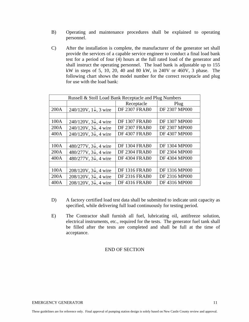
EMERGENCY GENERATOR 11
These guidelines are for reference only. Final approval of pumping station design is solely based on New Castle County review and approval.
B) Operating and maintenance procedures shall be explained to operating personnel.
C) After the installation is complete, the manufacturer of the generator set shall
provide the services of a capable service engineer to conduct a final load bank test for a period of four (4) hours at the full rated load of the generator and shall instruct the operating personnel. The load bank is adjustable up to 155 kW in steps of 5, 10, 20, 40 and 80 kW, in 240V or 460V, 3 phase. The following chart shows the model number for the correct receptacle and plug for use with the load bank:
Russell & Stoll Load Bank Receptacle and Plug Numbers Receptacle Plug 200A 240/120V, 1↓, 3 wire DF 2307 FRAB0 DF 2307 MP000 100A 240/120V, 3↓, 4 wire DF 1307 FRAB0 DF 1307 MP000 200A 240/120V, 3↓, 4 wire DF 2307 FRAB0 DF 2307 MP000 400A 240/120V, 3↓, 4 wire DF 4307 FRAB0 DF 4307 MP000 100A 480/277V, 3↓, 4 wire DF 1304 FRAB0 DF 1304 MP000 200A 480/277V, 3↓, 4 wire DF 2304 FRAB0 DF 2304 MP000 400A 480/277V, 3↓, 4 wire DF 4304 FRAB0 DF 4304 MP000 100A 208/120V, 3↓, 4 wire DF 1316 FRAB0 DF 1316 MP000 200A 208/120V, 3↓, 4 wire DF 2316 FRAB0 DF 2316 MP000 400A 208/120V, 3↓, 4 wire DF 4316 FRAB0 DF 4316 MP000 D) A factory certified load test data shall be submitted to indicate unit capacity as
specified, while delivering full load continuously for testing period.
E) The Contractor shall furnish all fuel, lubricating oil, antifreeze solution, electrical instruments, etc., required for the tests. The generator fuel tank shall be filled after the tests are completed and shall be full at the time of acceptance.
END OF SECTION
TELEMETRY SYSTEM 1 These guidelines are for reference only. Final approval of pumping station design is solely based on New Castle County review and approval.
TELEMETRY SYSTEM
PART 1 GENERAL 1.01 SCOPE OF WORK
A) Perform all work and furnish all equipment, labor, materials and appurtenances necessary to install a SCADA node at the pump station. The pump station will be added to the existing New Castle County SCADA system that is the Network 3000 system manufactured by Bristol Babcock, Inc., Watertown, CT.
B) During the pump station design process, the Engineer shall acquire the
services of Bristol Babcock – Radio Group or their authorized representative (currently Interface Inc., (410) 795-6795) to perform an in-field radio frequency (RF) survey. The radio survey shall be submitted to New Castle County for review.
C) Upon review of the RF survey, New Castle County shall determine the
appropriate method of telemetry. Unless proven technically unfeasible, radio telemetry will be chosen.
D) In no case shall pump station telemetry be furnished and installed without a
complete RF Survey as specified herein.
E) Due to changing technology and practices, these guidelines are for reference only. New Castle County reserves the right to update these guidelines without notification. All equipment and labor performed is subject to review and approval/acceptance by New Castle County.
1.02 SUBMITTALS
A) The Contractor shall list the name of the firm being subcontracted to perform the radio survey.
B) The Contractor shall submit the following for review and approval:
1) Name and credentials of firm subcontracted to perform the radio survey. 2) Completed radio survey report (see format sheets) attached.
3) Cut sheets, data, brochures, model numbers, etc., of all equipment being
furnished.
4) Name and credentials of firm (or person) providing software and programming support and/or training.
TELEMETRY SYSTEM 2 These guidelines are for reference only. Final approval of pumping station design is solely based on New Castle County review and approval.
1.03 OPERATION AND MAINTENANCE DATA
A) The Contractor shall provide three (3) copies of the following at the completion of the contract:
1) Final approved Radio Frequency Survey Report; 2) Operation and Maintenance Manual for the telemetry system. The O&M
Manual shall include detailed information for all equipment supplied, troubleshooting procedures, electrical schematics, programming guides, as-built drawings, etc.
1.04 QUALITY ASSURANCE
A) All materials and equipment shall be installed and completed in a workmanlike manner. Any material or equipment not installed shall be removed and replaced, as directed by New Castle County, at the expense of the Contractor.
1.05 RADIO SURVEY
A) The RF survey shall be performed to determine the following:
1) Feasibility of radio communication at the pump station at 928/952 MHZ band.
2) Determine antenna height and type requirements.
3) Determine alternative frequency communication availability, including
450 MHZ, 902-928 MHZ, spread spectrum, etc.
4) Produce a detailed field report suitable to become the basis of a submittal to the FCC for licensing purposes in the future.
B) The RF survey shall consist of the following activities:
1) A path study at various operating frequency bands 450 MHZ, 902-928 MHZ, spread spectrum, 928/952 MHZ. The path study shall consider paths to the existing RF repeaters/receivers and to other pump stations identified as potential hubs.
2) Survey of geographical and physical relationships of the paths.
Obstructions and interference, both physical and RF, line of sight availability, radio range, and topography shall be identified in the survey.
3) On-site RF measurements using sized transmitters and receivers. Actual
readings shall be taken with antennas and hardware that are representative of the equipment to be installed at the pump station.

TELEMETRY SYSTEM 3 These guidelines are for reference only. Final approval of pumping station design is solely based on New Castle County review and approval.
4) On-site RF measurements shall be taken at various antenna heights to
determine optimal height.
5) On-site RF measurements shall include field strength, path losses, and existing RF activity in the bank. Any interference shall be noted and the owner identified. The actions necessary to eliminate interferences shall be recommended in the final report.
6) The party performing the radio survey shall provide an estimate of the
probability of the proposed radio path communicating with the central in terms of a percentage.
7) If the Contractor elects to use an R.F. Survey Company other than Bristol
Babcock, New Castle County reserves the right to request additional credentials, resumes, user lists, etc., to determine the qualifications of the company used by the Contractor.
C) RF Survey Report
1) Upon completion of the RF Survey, a final report shall be submitted to the County for review.
2) The report shall summarize the RF Survey results, shall include RF path
calculations, and shall include field data captured. The report shall adhere to the format shown on the attached format sheets.
3) If upon review of the RF Survey Report, the County determines that the
information is insufficient or incomplete in any way, the contractor shall perform all necessary actions to complete the report at no additional cost to the County.
4) Once the County receives a complete report, it will review the report and
determine the telemetry method to be installed at that pump station, i.e., radio or phone line, and the applicable equipment at the pump station and Maintenance Base.
D) Radio Survey Format Sheet
1) See Format Sheet Table of Contents at end of section. PART 2 MATERIALS 2.01 GENERAL
A) All equipment shall be compatible with existing maintenance and test equipment and shall be interchangeable with existing system hardware. Therefore, all component hardware and software shall be by Bristol Babcock,

TELEMETRY SYSTEM 4 These guidelines are for reference only. Final approval of pumping station design is solely based on New Castle County review and approval.
Inc. The Contractor shall install this equipment under the direction of the manufacturer or his authorized representative.
2.02 DATA INPUT WITH ALARM POINTS
A) The pump station telemetry system shall perform the following requirements and shall be connected by the Contractor as follows:
1) #1 Pump Run Light 2) #2 Pump Run Light 3) High Wet Well Level 4) Power Failure 5) Intrusion alarm 6) Spare or (Generator Run) 7) Communication Failure Light 8) Flow Metering, if required 9) Wet Well level (analog) 10) Wet Well fan failure light, if required
B) All components shown on material list shall be furnished and installed. Note that Bristol Babcock does not furnish certain items. These items shall be furnished by the Contractor. All components shall be compatible to the existing system and each other.
C) The Contractor shall provide necessary interface wiring, power, and other
supporting requirements such as magnetic reed switches for intrusion and/or other switches or contacts for alarm points.
2.03 MATERIAL LIST FOR R.C. REMOTE UNIT – 928/952 FREQUENCY
A) The equipment listed herein represents the minimum or expected design. Actual equipment may vary as determined by the RF study and shall be included in the system.
1) Enclosure – Steel, NEMA 4, 36” x 24” x 8” with matching internal panel. 2) Process Controller – Bristol Babcock, Inc., RTU3305.
3) RF Transceiver – Microwave Data Corp., 5-watt power @ 12 VDC,
synthesized, 4-wire audio 1200 baud and loop back with diagnostics. Model No. MDS 2310.
a) Transmit Freq.: 928.64375 MHZ b) Receive Freq.: 952.64375 MHZ
4) Power Supplies

TELEMETRY SYSTEM 5 These guidelines are for reference only. Final approval of pumping station design is solely based on New Castle County review and approval.
a) Radio – Input 115 VAC, Output 12 VDC @ 4 amps with over voltage protection circuit. Electrostatics, Inc., Model 55-12-0.
b) Process Controller – Input 115 VAC, Output 12 VDC @ 1 amp with
over voltage protection circuit. Electrostatics, Inc., Model 30-24-0.
c) Manufacturers instruction manuals shall be included in each O&M Manual.
5) Filter – Corcom, Inc., Model 3VKI. 6) Circuit Breaker – 10 ampere. ETA, Inc., Model No. 42-01.
7) Heater – Chromolox, 250 watt with ceramic post insulators and secondary
insulation bushings OT-1225, 120V AC.
8) Thermostat – Fenwall, Model No. 30000-0, adjustable 00-3000OF.
9) Lightning Arrestor – Polyphaser Corp., Model ISB50LN-C-2.
10) Antenna Feed Cable
a) ½” low loss foam dielectric cable, type N connectors, male-top, female-bottom, length to suit conditions. Minimum 6” radius bend.
b) Jumper cable (bottom) – RG213/n, type N male connector. Length 3
ft.
11) Antenna – Direction Yagi, 10 dg gain. Decibel Products, Inc., Model DB499K.
12) A.C. outlet strip for three receptacles with power supply circuit breaker.
Supplied in the NEMA 4 panel.
13) The antenna tower shall be of galvanized steel or aluminum construction, designed and supported to withstand loadings per applicable code requirements (minimum 70-mph wind loads). Tower heights up to forty-five feet shall be supplied, as determined from the RF survey. Tower foundation design per manufacturer’s specifications. Tower shall include lightning protection per NEC requirements.
a) For sub-grade flooded suction pumping stations, the radio shall be
housed in a 16” x 20” NEMA 4 enclosure and mounted on the tower via 1½” x 1½” galvanized Uni-strut supports with stainless steel bolts. Power and signal wire shall be run in ¾” conduit from the pump station. Power shall be supplied from the power panel via 14 AWG (R&B) wire. Signal wire shall be 9 Conductor, 22 AWG wire.
TELEMETRY SYSTEM 6 These guidelines are for reference only. Final approval of pumping station design is solely based on New Castle County review and approval.
14) Discrete output card, open drain, 16 outputs, code E6, Bristol No. 372586-01-1 (for base unit.)
2.04 MATERIAL LIST FOR R.C. REMOTE UNIT– SPREAD SPECTRUM
B) The equipment listed above represents the minimum or expected design. Actual equipment may vary as determined by the RF Study and shall be included in the system.
1) Enclosure – Steel, NEMA 4, 36” X 24” X 8” with matching internal panel.
2) Process Controller – Bristol Babcock, Inc., RTU3305.
a) Manufacturers instruction manuals shall be included in each O&M
Manual.
3) RF Transceiver – Microwave Data Corp., Model No. MDS 9810.
a) Manufacturers instruction manuals shall be included in each O&M Manual.
4) Power Supplies
a) Radio – Input 115 VAC, Output 12 VDC @ 4 amps with over voltage protection circuit. Electrostatics, Inc., Model 55-12-0.
b) Process Controller – Input 115 VAC, Output 12VDC @ 1 amp with
over voltage protection circuit. Electrostatics, Inc., Model 30-24-0.
c) Manufacturers instruction manuals shall be included in each O&M Manual.
5) Filter – Corcom, Inc., Model 3VKI 6) Circuit Breaker – 10 ampere. ETA, Inc., Model No. 42-01.
7) Heater – Chromolox, 250 watt with ceramic post insulators and secondary
insulation bushings OT-1225, 120V AC.
8) Thermostat – Fenwall, Model No. 30000-0, adjustable 00-3000OF.
9) Lightning Arrestor – Polyphaser Corp., Model ISB50LN-C2.
10) Antenna Feed Cable
a) ½” low loss foam di-electric cable, type N connectors, male-top, female-bottom, length to suit conditions. Minimum 6” radius bend.

TELEMETRY SYSTEM 7 These guidelines are for reference only. Final approval of pumping station design is solely based on New Castle County review and approval.
b) Jumper cable (bottom) – RG213/n, type N male connector. Length 3 ft.
11) Antenna – 60 db gain 12) A.C. outlet strip for three receptacles with power supply circuit breaker.
Supplied in the NEMA IV panel.
13) The antenna tower shall be of galvanized steel or aluminum construction, designed and supported to withstand loadings per applicable code requirements (minimum 70-mph wind loads). Tower heights up to forty-five feet shall be supplied, as determined from the RF survey. Tower foundation design per manufacturer’s specifications. Tower shall include lighting protection per NEC requirements.
a) For sub-grade flooded suction pumping stations, the radio shall be
housed in a 16” x 20” NEMA 4 enclosure and mounted on the tower via 1½” x 1½” galvanized Uni-strut supports with stainless steel bolts. Power and signal wire shall be run in ¾” conduit from the pump station. Power shall be supplied from the power panel via 14 AWG (R&B) wire. Signal wire shall be 9 Conductor, 22 AWG wire.
14) Discrete output card, open drain, 16 outputs, code E6, Bristol No. 372586-
01-0 (for base unit.) 2.05 TELEPHONE COMMUNICATION
A) For those pump stations that have been designated by the New Castle County as phone communication sites, the Contractor shall provide telephone entrance conduit with conductors including pull wire, as shown on the drawings. Conduit installation shall conform to the requirements of the applicable Phone Company.
B) The leased phone lines shall be ordered and paid for by the Contractor. They
shall be two-wire, Type 3001, or R3VM-NA for voice grade service without signal tone, except that end-to-end circuit loss shall not exceed 20 dbmo.
C) The Contractor shall call the appropriate Phone Company and request service,
giving origination address and calling exchange and destination address (New Castle County Maintenance Base at 100 New Churchmans Road) and call exchange and asking for installation cost and initial billing cost. These costs shall be compensated to the Contractor with accompanying proof of payment.
D) Note that all telemetry requirements apply for phone communication system,
including start-up and technical support.
E) Data Input w/Alarm Points
TELEMETRY SYSTEM 8 These guidelines are for reference only. Final approval of pumping station design is solely based on New Castle County review and approval.
1) The system shall perform the following requirements and shall be
connected by the Contractor as follows:
a) #1 Pump Run Light b) #2 Pump Run Light c) High Wet Well Level d) Power Failure e) Intrusion Alarm f) Spare or (Generator Run) g) Communication Failure Light h) Flow Metering (if required) i) Wet Well Level Analog (4-20mA)
2.06 MATERIAL LIST FOR PHONE COMMUNICATION – REMOTE UNIT
A) Enclosure (outdoor use) NEMA IV, 24”WX30” HX12”D, gray epoxy finish
w/internal mounting plate. Bristol Model 8742-10A-200-000-211-113-100.
B) Chromolox strap heater, Type T, and Fenwal Thermostat Series 30000.
C) Model 8510-10A-XOA-T24 UPS uninterruptable power supply.
D) Model 8792-20A 4-wire surge protector.
E) AC terminal block, 1 AC surge protector and circuit breaker.
F) Process Controller – Bristol Babcock, Inc. RTU 3305 with built-in 9600 baud modem with analog inputs and outputs.
G) Lightning Arrestor – Bristol No. 8792-14A.
H) A.C. Outlet Strip for three receptacles with power supply circuit breaker. This
item to be furnished and installed by the Contractor in NEMA IV panel.
I) Caution Plate 115 V – Bristol No. 386050-01-5.
J) Discrete output card, open drain, 16 outputs, code E6, Bristol No. 392586-01-1 (for base unit.)
K) Multimeter/Loop Calibrator, precision 1000V, 440 mA digital multimeter, DC
current source loop calibrator. Fluke model 787 process meter.
L) Tie into existing 3000 ACCOL II system in Central Station.
TELEMETRY SYSTEM 9 These guidelines are for reference only. Final approval of pumping station design is solely based on New Castle County review and approval.
PART 3 EXECUTION 3.01 INSTALLATION
A) Install Telemetry System in accordance with manufacturer’s recommendations. Install equipment at the proper location.
B) Programming shall be in coordination with New Castle County’s requirements
and shall be performed and demonstrated by the Contractor.
3.02 START-UP AND TECHNICAL SUPPORT
A) The manufacturer or his authorized representative shall witness the start-up of the pump station telemetry system.
B) In conjunction with the start-up of the pump station telemetry, the Contractor
shall provide manufacturer’s programming support and/or training at the County’s site to integrate the new pump station into the existing system.
1) Programming support shall be in system programming (ACCOL) or Man-
Machine interface programming (ICONICS) as determined by New Castle County.
2) Training shall be in ACCOL, 33xx hardware, or ICONICS as determined
by New Castle County.
3) The trainer shall be a direct employee of the manufacturer who is engaged in system training on a regular basis.
4) In lieu of the site training, New Castle County may elect one of the
following Bristol Babcock Educational Services Courses: ACCOL I (No. 411); ACCOL II (No. 412); 33xx Hardware Part I (No. 301); 33xx Hardware Part II (No. 302) ; RTU 3305 Configuration (No. 303).
5) The Contractor shall enroll one county employee in the selected course
and submit receipts to New Castle County to verify that tuition has been paid.
END OF SECTION
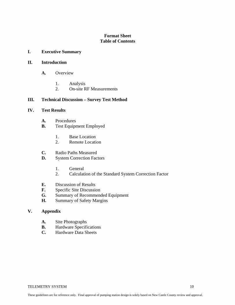
TELEMETRY SYSTEM 10 These guidelines are for reference only. Final approval of pumping station design is solely based on New Castle County review and approval.
Format Sheet
Table of Contents
I. Executive Summary II. Introduction A. Overview 1. Analysis 2. On-site RF Measurements III. Technical Discussion – Survey Test Method IV. Test Results A. Procedures B. Test Equipment Employed 1. Base Location 2. Remote Location C. Radio Paths Measured D. System Correction Factors 1. General 2. Calculation of the Standard System Correction Factor E. Discussion of Results F. Specific Site Discussion G. Summary of Recommended Equipment H. Summary of Safety Margins V. Appendix A. Site Photographs B. Hardware Specifications C. Hardware Data Sheets