Embed Size (px)
Citation preview

Pololu Orangutan USB Programmer User's Guide
1. Overview
The Orangutan USB Programmer is a compact solution for programming our Orangutan robot controllers or 3pi robotthrough a USB port. Our programmer incorporates a USB-to-serial adapter and emulates an AVR ISP programmer so that you can program your Orangutans or 3pi with any software that can talk through a serial port to an AVR ISP. The unit also doubles as a USB-to-serial adapter (TX and RX only), allowing you to communicate with your Orangutan, 3pi,or any other microcontroller, through a terminal program.
Unlike some other AVR programmers, the Orangutan USB programmer does not recieve its power from the circuit to be programmed. Instead, it receives its power via the USB A to mini-B cable that connects it to a personal computer. Thiscable is not included with your programmer; if you do not already have one, you can purchase it separately from our website. The 6-pin ISP programming cable that connects the programmer to your target device is included.
Note: The Orangutan USB programmer should be able to program all AVR microcontrollers that support paged program and EEPROM memory, but we can only support Orangutan and 3pi programming at this time. This product is not neededfor the Orangutan X2, which has its own built-in AVR ISP programmer.
For a Spanish version of this document, please see Pololu Orangutan USB Programmer Guia Usuario (1358k pdf) (provided by customer Jaume B.).
2. Module Pinout and Components

Pololu Orangutan USB Programmer labeled top view
Pololu Orangutan USB Programmer labeled bottom view
USB-to-Serial Adapter Mode:The location of the blue mode jumper determines whether the device will function as a programmer or a USB-to-serialadapter. When the mode jumper spans the two pins that are marked on the bottom of the board with a “U”, thecomputer’s RX line is connected to the pad labeled RX and the device will function as a basic USB-to-serial adapter. TheRX and TX pads are labeled from the computer’s perspective, so to make use of the USB-to-serial adapter you need toconnect the programmer’s RX pad to your target’s TX pin (PD1 on the Orangutan/3pi) and the TX pad to your target’sRX pin (PD0 on the Orangutan/3pi) while in USB-to-serial mode. These pads expect logic-level signals (i.e. 0 V lows,5 V highs).
Programmer Mode:When the blue mode jumper spans the two pins that are marked on the bottom of the board with a “P”, the computer’sRX line is connected to the programming microcontroller and the device will function as an in-circuit AVR ISPprogrammer. The computer’s TX line is always connected to both the pad labeled TX and the programmingmicrocontroller.
Revision Number:There are currently two versions of the Orangutan USB Programmer: PGM02A and PGM02B. The programmer’srevision number is written along the right side of the bottom of the PC board. The newer PGM02B revision has two key improvements over the original PGM02A: 1) it has the ability to accept firmware updates from Pololu and 2) it won’t letyou program your target device if that device is not powered, which can help prevent you from accidentally damagingyour Orangutan/3pi. Please take note of your programmer’s revision number so you know which statements in this user’sguide apply to your specific programmer.
LEDs:The green USB status LED near the mini-B connector will light when the Orangutan USB programmer is connected to apersonal computer and functioning properly as a serial port. If you have not installed the programmer’s drivers beforeconnecting it, this status LED will be off.
The red and green programming status LEDs near the center of the board will give you feedback when the Orangutan USB programmer is being used in programming mode. The green LED will flash every time the programmer receives a valid AVR ISP command packet from the personal computer to which it is connected. The red LED will flash every time the programmer sends information over the 6-pin ISP cable to the device being programmed. These LEDs do not do anything when the Orangutan USB programmer is in USB-to-serial mode.
If you have programmer version PGM02B, you will have additional LED feedback. Every time your programmer powersup (i.e. when you connect it to your computer), the red and green status LEDs will both light for five seconds. During thisperiod, the programmer is receptive to firmware updates; you should avoid trying to program until the initial five secondshave elapsed and the two status LEDs have turned off. Additionally, if your programmer is not connected to a targetdevice or if your target device is not powered, the programmer’s red LED will flash once per second to indicate that it will not let you program.
Connecting to Your 3pi Robot:

The Orangutan USB programmer connects to your 3pi robot via the included 6-pin ISP cable, which plugs into the 3pi’skeyed ISP port located just behind the right wheel as shown above.
Connecting to Your Orangutan:
Baby Orangutan ISP pins Orangutan ISP pins
The Orangutan USB programmer connects to your Orangutan or Baby Orangutan via the included 6-pin ISP cable. Thecable must be oriented so that the programmer’s ISP header pin 1 connects to your (Baby) Orangutan’s ISP header pin 1.Unlike the Orangutan and Orangutan LV-168, the Baby Orangutan does not come with a shrouded header to enforcecorrect cable orientation; the red wire and arrow mark on the cable’s ISP connector should be lined up with the arrow to pin 1 on the Baby Orangutan PCB. You will only be able to achieve this alignment by connecting to the top side of the Baby Orangutan PCB, so be very careful not to solder your 6-pin ISP header onto the wrong side of your Baby Orangutan!
Note: The programmer does not deliver power to the device it is programming, so your Orangutan must be turned on to be programmed. If you are using programmer version PGM02A, attempting to program anunpowered device will have unpredictable results; this might randomly change the fuse settings, which can in turnpermanently disable your Orangutan. If your programmer version is PGM02B, the programmer will not let you

program an unpowered device (you will see the red status LED blink once per second if your target device is not powered).
3. USB-to-Serial Drivers
Before you connect your Orangutan USB programmer to your computer, you must install the driver for theprogrammer’s CP2102 USB-to-UART bridge. Once you have successfully installed your this driver, you should see the green USB status LED near the mini-B connector lit whenever it is connected to your computer.
4. Getting Started Using Windows
After you’ve installed the necessary drivers, the next step is to download and install a compiler. WinAVR, located athttp://winavr.sourceforge.net/, is an open source suite of software development tools for the Atmel AVR series of microcontrollers. It includes the GNU GCC compiler for C and C++. Follow the installation instructions they provide.
WinAVR alone will give you all the tools you need to start programming your Orangutan or 3pi robot, but Atmel offers AVR Studio, a free integrated development environment that works with the GCC C/C++ compiler. AVR Studio includes a simulator and other useful tools, and supports the AVR ISP protocol used by the Orangutan USB programmer.You can download AVR Studio from http://www.atmel.com/avrstudio/. Follow Atmel’s installation instructions. Notethat newer versions of AVR Studio might not work with older versions of WinAVR, so we recommend you upgrade tothe newest version WinAVR every time you get a new version of AVR Studio.
5.a. Using AVR Studio
Note: The instructions in this section were written for AVR Studio version 4.13, build 528. The most recent version ofAVR Studio at the time of this update is version 4.13 Service Pack 2, build 571. The AVRISP dialog has changedslightly in this newer version, so the screen shots you see in this section may differ from what you see when you runAVR Studio.
Here we will show you step by step how to use AVR Studio make the red user LED blink on your Orangutan, Orangutan LV-168, Baby Orangutan, or 3pi robot. If you want to skip the steps that setup the LED-blinker code and jump straight into using your Orangutan USB programmer, you can download the AVR Studio project these steps would help youcreate—BlinkLED.zip (14k zip from pololu.com)—and proceed straight to step 4. Please note that this BlinkLEDprogram will not work on the Orangutan X2.
Open AVR Studio and click New Project. Select AVR GCC for the project type. We called our project“BlinkLED” and elected to have a folder called “C:\BlinkLED” created containing the blank file “BlinkLED.c”.Click Next >>. DO NOT click “Finish” yet. If you do accidentally click “Finish”, you will not be able to performstep 2 and will instead have to set the device by going to the Project menu and selecting “Configuration Options”.
1.
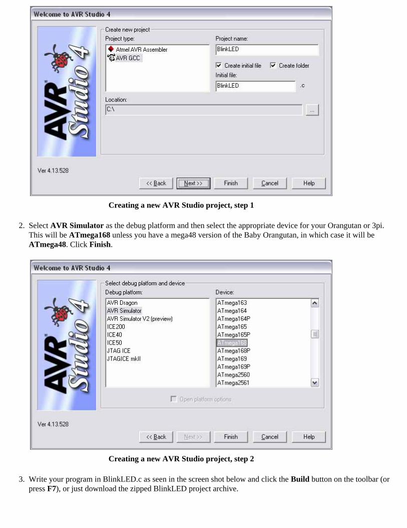
Creating a new AVR Studio project, step 1
Select AVR Simulator as the debug platform and then select the appropriate device for your Orangutan or 3pi. This will be ATmega168 unless you have a mega48 version of the Baby Orangutan, in which case it will be ATmega48. Click Finish.
Creating a new AVR Studio project, step 2
2.
Write your program in BlinkLED.c as seen in the screen shot below and click the Build button on the toolbar (or press F7), or just download the zipped BlinkLED project archive.
3.

Building a project with AVR Studio
Note: You will probably want to customize this program slightly if you are working with an Orangutan rather thana Baby Orangutan, Orangutan LV-168, or 3pi robot. F_CPU should be defined as the clock frequency of your target device in Hz. For the Orangutan this should be 8000000UL (8 MHz), while for the Orangutan LV-168, BabyOrangutan, and 3pi robot this should be 20000000UL (20 MHz). You can achieve this by commenting out line 3and uncommenting line 2. If you don’t make this change, the timing of delayms() will be off.
Make sure your Orangutan USB programmer is connected to your computer via its USB A to mini-B cable and then click the Display the ‘Connect’ Dialog button on the toolbar . You can also accomplish this by going to the Tools menu and selecting Program AVR -> Connect….
Connecting to the programmer with AVR Studio
4.
This will bring up a programmer selection dialog. The platform should be STK500 or AVRISP. The Orangutan 5.
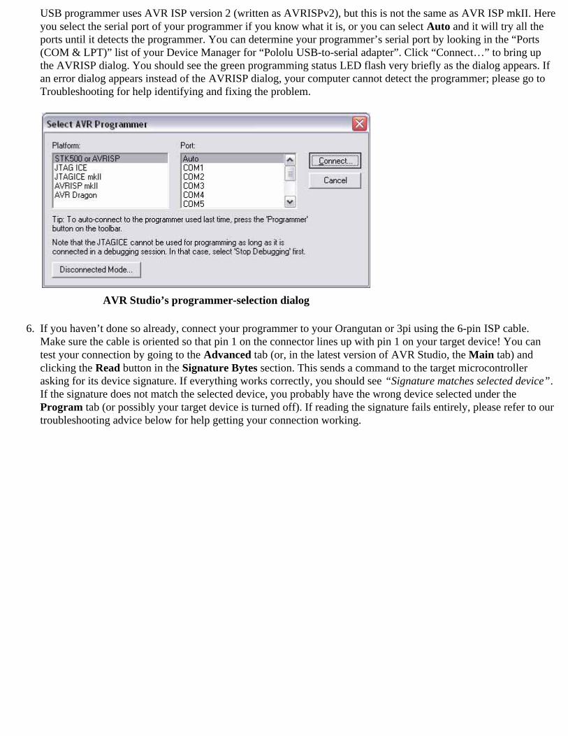
USB programmer uses AVR ISP version 2 (written as AVRISPv2), but this is not the same as AVR ISP mkII. Hereyou select the serial port of your programmer if you know what it is, or you can select Auto and it will try all theports until it detects the programmer. You can determine your programmer’s serial port by looking in the “Ports(COM & LPT)” list of your Device Manager for “Pololu USB-to-serial adapter”. Click “Connect…” to bring upthe AVRISP dialog. You should see the green programming status LED flash very briefly as the dialog appears. If an error dialog appears instead of the AVRISP dialog, your computer cannot detect the programmer; please go to Troubleshooting for help identifying and fixing the problem.
AVR Studio’s programmer-selection dialog
If you haven’t done so already, connect your programmer to your Orangutan or 3pi using the 6-pin ISP cable.Make sure the cable is oriented so that pin 1 on the connector lines up with pin 1 on your target device! You cantest your connection by going to the Advanced tab (or, in the latest version of AVR Studio, the Main tab) and clicking the Read button in the Signature Bytes section. This sends a command to the target microcontrollerasking for its device signature. If everything works correctly, you should see “Signature matches selected device”. If the signature does not match the selected device, you probably have the wrong device selected under the Program tab (or possibly your target device is turned off). If reading the signature fails entirely, please refer to ourtroubleshooting advice below for help getting your connection working.
6.
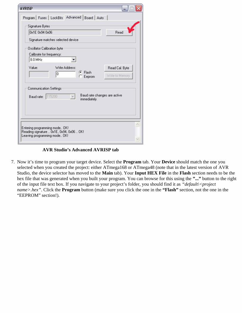
AVR Studio’s Advanced AVRISP tab
Now it’s time to program your target device. Select the Program tab. Your Device should match the one youselected when you created the project: either ATmega168 or ATmega48 (note that in the latest version of AVRStudio, the device selector has moved to the Main tab). Your Input HEX File in the Flash section needs to be the hex file that was generated when you built your program. You can browse for this using the ”...” button to the rightof the input file text box. If you navigate to your project’s folder, you should find it as “default\<projectname>.hex”. Click the Program button (make sure you click the one in the “Flash” section, not the one in the“EEPROM” section!).
7.
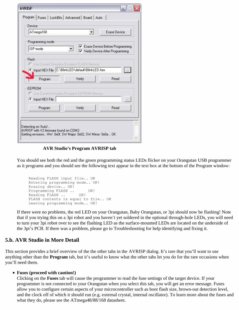
AVR Studio’s Program AVRISP tab
You should see both the red and the green programming status LEDs flicker on your Orangutan USB programmer as it programs and you should see the following text appear in the text box at the bottom of the Program window:
Reading FLASH input file.. OKEntering programming mode.. OK!Erasing device.. OK!Programming FLASH .. OK!Reading FLASH .. OK!FLASH contents is equal to file.. OKLeaving programming mode.. OK!
If there were no problems, the red LED on your Orangutan, Baby Orangutan, or 3pi should now be flashing! Notethat if you trying this on a 3pi robot and you haven’t yet soldered in the optional through-hole LEDs, you will needto turn your 3pi robot over to see the flashing LED as the surface-mounted LEDs are located on the underside ofthe 3pi’s PCB. If there was a problem, please go to Troubleshooting for help identifying and fixing it.
5.b. AVR Studio in More Detail
This section provides a brief overview of the the other tabs in the AVRISP dialog. It’s rare that you’ll want to useanything other than the Program tab, but it’s useful to know what the other tabs let you do for the rare occasions whenyou’ll need them.
Fuses (proceed with caution!)Clicking on the Fuses tab will cause the programmer to read the fuse settings of the target device. If yourprogrammer is not connected to your Orangutan when you select this tab, you will get an error message. Fusesallow you to configure certain aspects of your microcontroller such as boot flash size, brown-out detection level,and the clock off of which it should run (e.g. external crystal, internal oscillator). To learn more about the fuses andwhat they do, please see the ATmega48/88/168 datasheet.
Note: You can permanently disable your Orangutan by setting the fuses incorrectly. Only advanced userswho know precisely what they are doing should change these fuse settings!
Lock BitsClicking on the Lock Bits tab will cause the programmer to read the lock bits settings of the target device. If yourprogrammer is not connected to your Orangutan when you select this tab, you will get an error message. The lockbits allow you to secure your microcontroller by preventing further flash writing or reading. The lock bits can bereset to a fully unlocked state by performing a chip erase (i.e. by clicking the Erase Device button in the Programtab). Lock bits are usually only important if you wish to release a product to other people without giving themaccess to the program its running, or if you wish to make it slightly more difficult to overwrite a programmed chip.
Advanced (or Main)Reading the device signature is a good way to test if your programmer is properly connected to your Orangutan.You shouldn’t need to worry about Oscillator Calibration. Please see step 6 of the Section 5.a for more details on reading a device signature. Note that the latest version of AVR Studio has moved the device signature interface to the Main tab.
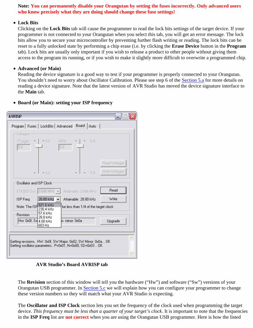
Board (or Main): setting your ISP frequency
AVR Studio’s Board AVRISP tab
The Revision section of this window will tell you the hardware (“Hw”) and software (“Sw”) versions of yourOrangutan USB programmer. In Section 5.c we will explain how you can configure your programmer to change these version numbers so they will match what your AVR Studio is expecting.
The Oscillator and ISP Clock section lets you set the frequency of the clock used when programming the target device. This frequency must be less than a quarter of your target’s clock. It is important to note that the frequencies in the ISP Freq list are not correct when you are using the Orangutan USB programmer. Here is how the listed
frequencies relate to the actual frequencies:
Listed Frequency Actual Frequency Allowed Target Frequency
921.6 kHz 2.5 MHz > 10 MHz230.4 kHz 1.25 MHz > 5 MHz57.6 kHz 625 kHz > 2.5 MHz28.8 kHz 156 kHz > 625 kHz4.00 kHz 3.91 kHz > 16 kHz603 Hz* 610 Hz* > 2.5 kHz*
* This ISP frequency is so low that AVR Studio times out when it tries to program flash or EEPROM, but it can be used to program fuses and lock bits. You should be able to program any device running 1 MHz or higher using the listed28.8 kHz setting, which is the Orangutan USB programmer’s default ISP frequency. An 8 MHz device (e.g. theOrangutan) can be safely programmed using the 230.4 kHz setting and a 20 MHz device (e.g. the OrangutanLV-168 and Baby Orangutan) can be safely programmed using the fastest 921.6 kHz setting. The two lowestfrequencies exist as a safety net in case you accidentally set the clock of your target device to something under1 MHz. The 603 Hz setting is too slow to actually program your target device (AVR Studio will time out waitingfor a response from your Orangutan), but it will still let you set the fuses. Be aware that if you attempt to programflash or EEPROM using the 4.00 kHz setting, it might take somewhere on the order of five to ten minutesdepending on the size of your program, so you should only use this ISP frequency as a last resort.
Note: In the latest version of AVR Studio, the interface for setting your programmer’s ISP frequency has moved to the Main tab.
AutoThis tab lets you automatically perform a scripted set of programming actions. If you are going to be configuringmany devices the same way, it might be convenient for you to do this using the Auto tab features.
5.c. Configuring Your Programmer for AVR Studio
Configuring your programmer’s version numbers is purely optional. Your programmer will still function with incorrector mismatched version numbers.
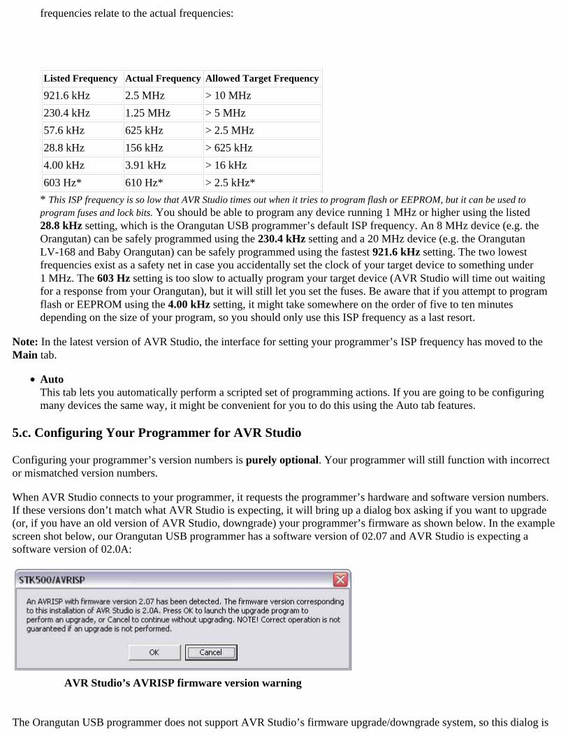
When AVR Studio connects to your programmer, it requests the programmer’s hardware and software version numbers.If these versions don’t match what AVR Studio is expecting, it will bring up a dialog box asking if you want to upgrade (or, if you have an old version of AVR Studio, downgrade) your programmer’s firmware as shown below. In the examplescreen shot below, our Orangutan USB programmer has a software version of 02.07 and AVR Studio is expecting a software version of 02.0A:
AVR Studio’s AVRISP firmware version warning
The Orangutan USB programmer does not support AVR Studio’s firmware upgrade/downgrade system, so this dialog is
nothing more than an annoyance that we will have to dismiss every time we try to bring up the AVRISP dialog. PressingOK will result in AVR Studio’s attempting (and failing) to upgrade our programmer’s firmware, so the proper response isto press Cancel to proceed to the AVRISP dialog. The warning can be safely ignored, so to stop AVR Studio fromissuing it we can configure the programmer’s software and version hardware numbers to match what AVR Studio is expecting.
The first step in the configuration process is to determine the COM port of your Orangutan USB programmer. One wayto do this is to bring up your computer’s Device Manager, expand the “Ports (COM & LPT)” list, and note the COM portassociated with “Pololu USB-to-serial adapter”. Use your favorite terminal program to connect to this port at 115,200baud with 8-bit characters, no parity and one stop bit. This is occasionally represented as 115200-8-N-1. In the screen shots below we use Hyper Terminal for this.
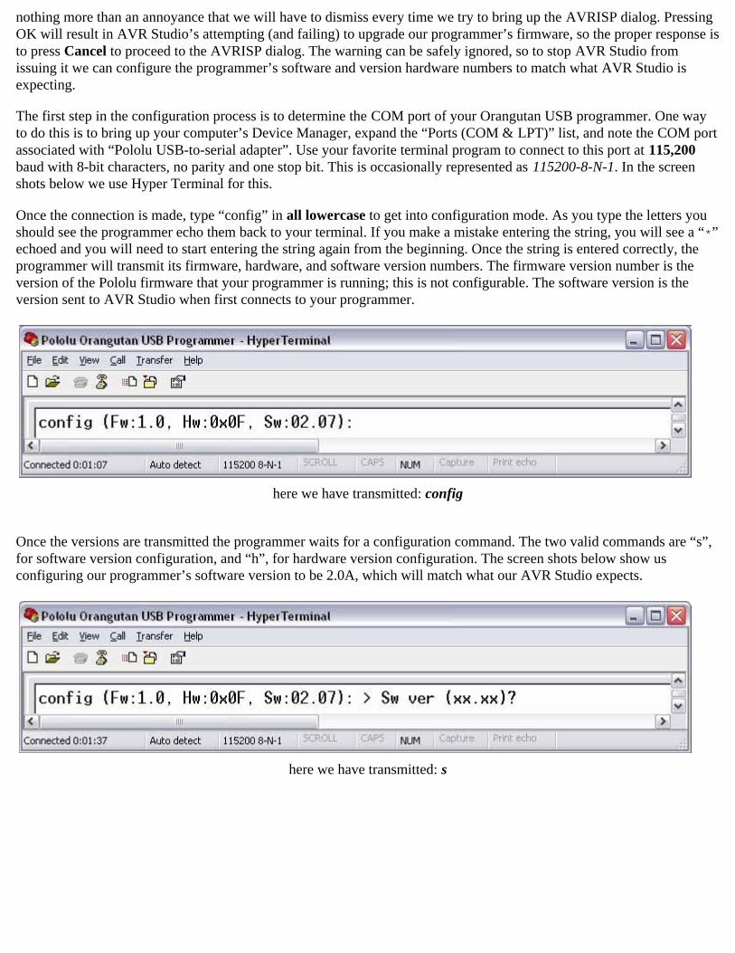
Once the connection is made, type “config” in all lowercase to get into configuration mode. As you type the letters youshould see the programmer echo them back to your terminal. If you make a mistake entering the string, you will see a “*”echoed and you will need to start entering the string again from the beginning. Once the string is entered correctly, theprogrammer will transmit its firmware, hardware, and software version numbers. The firmware version number is theversion of the Pololu firmware that your programmer is running; this is not configurable. The software version is theversion sent to AVR Studio when first connects to your programmer.
here we have transmitted: config
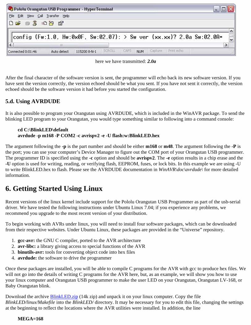
Once the versions are transmitted the programmer waits for a configuration command. The two valid commands are “s”,for software version configuration, and “h”, for hardware version configuration. The screen shots below show usconfiguring our programmer’s software version to be 2.0A, which will match what our AVR Studio expects.
here we have transmitted: s
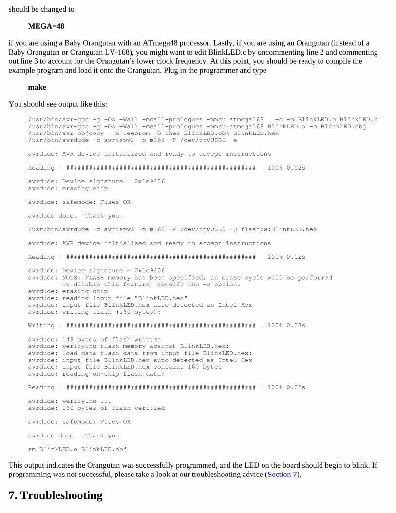
here we have transmitted: 2.0a
After the final character of the software version is sent, the programmer will echo back its new software version. If youhave sent the version correctly, the version echoed should be what you sent. If you have not sent it correctly, the versionechoed should be the software version it had before you started the configuration.
5.d. Using AVRDUDE
It is also possible to program your Orangutan using AVRDUDE, which is included in the WinAVR package. To send the blinking LED program to your Orangutan, you would type something similar to following into a command console:
cd C:\BlinkLED\defaultavrdude -p m168 -P COM2 -c avrispv2 -e -U flash:w:BlinkLED.hex
The argument following the -p is the part number and should be either m168 or m48. The argument following the -P isthe port; you can use your computer’s Device Manager to figure out the COM port of your Orangutan USB programmer. The programmer ID is specified using the -c option and should be avrispv2. The -e option results in a chip erase and the -U option is used for writing, reading, or verifying flash, EEPROM, fuses, or lock bits. In this example we are using -U to write BlinkLED.hex to flash. Please see the AVRDUDE documentation in WinAVR\doc\avrdude\ for more detailed information.
6. Getting Started Using Linux
Recent versions of the linux kernel include support for the Pololu Orangutan USB Programmer as part of the usb-serialdriver. We have tested the following instructions under Ubuntu Linux 7.04; if you experience any problems, werecommend you upgrade to the most recent version of your distribution.
To begin working with AVRs under linux, you will need to install four software packages, which can be downloadedfrom their respective websites. Under Ubuntu Linux, these packages are provided in the “Universe” repository.
gcc-avr: the GNU C compiler, ported to the AVR architecture 1.avr-libc: a library giving access to special functions of the AVR2.binutils-avr: tools for converting object code into hex files 3.avrdude: the software to drive the programmer4.
Once these packages are installed, you will be able to compile C programs for the AVR with gcc to produce hex files. Wewill not go into the details of writing C programs for the AVR here, but, as an example, we will show you how to use your linux computer and Orangutan USB programmer to make the user LED on your Orangutan, Orangutan LV-168, or Baby Orangutan blink.
Download the archive BlinkLED.zip (14k zip) and unpack it on your linux computer. Copy the file BlinkLED/linux/Makefile into the BlinkLED/ directory. It may be necessary for you to edit this file, changing the settingsat the beginning to reflect the locations where the AVR utilities were installed. In addition, the line
MEGA=168
should be changed to
MEGA=48
if you are using a Baby Orangutan with an ATmega48 processor. Lastly, if you are using an Orangutan (instead of aBaby Orangutan or Orangutan LV-168), you might want to edit BlinkLED.c by uncommenting line 2 and commentingout line 3 to account for the Orangutan’s lower clock frequency. At this point, you should be ready to compile theexample program and load it onto the Orangutan. Plug in the programmer and type
make
You should see output like this:
/usr/bin/avr-gcc -g -Os -Wall -mcall-prologues -mmcu=atmega168 -c -o BlinkLED.o BlinkLED.c/usr/bin/avr-gcc -g -Os -Wall -mcall-prologues -mmcu=atmega168 BlinkLED.o -o BlinkLED.obj/usr/bin/avr-objcopy -R .eeprom -O ihex BlinkLED.obj BlinkLED.hex/usr/bin/avrdude -c avrispv2 -p m168 -P /dev/ttyUSB0 -e
avrdude: AVR device initialized and ready to accept instructions
Reading | ################################################## | 100% 0.02s
avrdude: Device signature = 0x1e9406avrdude: erasing chip
avrdude: safemode: Fuses OK
avrdude done. Thank you.
/usr/bin/avrdude -c avrispv2 -p m168 -P /dev/ttyUSB0 -U flash:w:BlinkLED.hex
avrdude: AVR device initialized and ready to accept instructions
Reading | ################################################## | 100% 0.02s
avrdude: Device signature = 0x1e9406avrdude: NOTE: FLASH memory has been specified, an erase cycle will be performed To disable this feature, specify the -D option.avrdude: erasing chipavrdude: reading input file "BlinkLED.hex" avrdude: input file BlinkLED.hex auto detected as Intel Hexavrdude: writing flash (160 bytes):
Writing | ################################################## | 100% 0.07s
avrdude: 148 bytes of flash writtenavrdude: verifying flash memory against BlinkLED.hex:avrdude: load data flash data from input file BlinkLED.hex:avrdude: input file BlinkLED.hex auto detected as Intel Hexavrdude: input file BlinkLED.hex contains 160 bytesavrdude: reading on-chip flash data:
Reading | ################################################## | 100% 0.05s
avrdude: verifying ...avrdude: 160 bytes of flash verified
avrdude: safemode: Fuses OK
avrdude done. Thank you.
rm BlinkLED.o BlinkLED.obj
This output indicates the Orangutan was successfully programmed, and the LED on the board should begin to blink. Ifprogramming was not successful, please take a look at our troubleshooting advice (Section 7).
7. Troubleshooting

If Your Computer Fails to Connect to the Programmer
Make sure your programmer is connected to your computer via a USB A to mini-B cable. If it was previouslyworking and has since stopped, try cycling the power by unplugging it from your computer and then reconnectingit. Make sure you have installed the drivers the Orangutan USB programmer needs to operate. Is the programmer’s green USB status LED on? This is the single LED on the same side of the board as the mini-Bconnector. If this LED is not on, you do not have a valid USB-to-serial connection between your programmer and your computer. If you are running Windows, can you see your programmer listed among your Device Manager’s COM ports? Ifyou expand your Device Manager’s “Ports (COM & LPT)” list, you should see your programmer appear as“Pololu USB-to-serial adapter”.If you are running linux, examine the system messages generated when the programmer is connected, using thecommand “dmesg”.Your computer will only let one program have a given COM port open at a time. If you are connected to your Orangutan USB programmer’s COM port using another program, such as Hyper Terminal or a second instance of AVR Studio, you will not be able to connect to it with your programming software. Please make sure you don’thave any terminal programs connected to your programmer, and if you have multiple versions of AVR Studiorunning, make sure that you have closed the “AVRISP” programming dialogs in all of them. When the AVRISPdialog is open, that instance of AVR Studio has an open serial connection to your programmer. If you are using AVR Studio, try connecting to your programmer’s specific COM port instead of selecting the“Auto” option, which attempts to locate the port automatically.Is your programmer’s blue mode jumper selecting for programming mode? If the mode jumper is missing or isselecting USB-to-serial adapter mode, your computer will not detect it as a programmer.If none of the above work, try connecting to your programmer using a terminal program to verify that it’s alive.Please see the Configuring Your Programmer for AVR Studio section for instructions on how you can interact withyour Orangutan USB programmer using a terminal program.
If Your Programmer Has Problems Connecting to Your Target Device
The most common cause for this problem is an incorrect connection between your programmer and your target device. If the ISP pins are misaligned between your programmer and your target device, the two will not be able tocommunicate. Please make sure that the ISP pins as numbered in the Module Pinout & Components section arecorrectly connected between your Orangutan and your programmer (i.e. 1 goes to 1, 2 goes to 2, etc.).Your target must be powered for programming to work. Please make sure that your Orangutan has power and is turned on. Your programmer’s ISP frequency must not be more than a quarter of your target device’s clock frequency. If youare having trouble communicating with your target device, try lowering the ISP frequency using the Board tab of AVR Studio’s AVRISP dialog. For more information about ISP frequency, see the Board section. There may be a problem with your target device. It’s possible to kill a device with a static shock, by incorrectlyconnecting power, or by programming the fuses incorrectly. There could also be a short or cut trace somewhere onyour target device. The ideal way to test for this would be to try programming a different device with yourOrangutan USB programmer (or, conversely, try using a different programmer to program your target device). Ifthis is not an option, try verifying that your target device is still functional and perform some continuity tests tocheck for shorts or disconnections on the ISP programming lines. Don’t forget to check the 6-pin ISP cable for shorts as well.
If none of the above troubleshooting suggestions help, please contact us for support.
8. Updating Your Programmer's Firmware

Note: Only programmer revision PGM02B supports firmware upgrades. If you have revision PGM02A, this section does not apply to your product.
On August 20, 2008 we released a firmware update (firmware version 1.4) for the Orangutan USB programmer revision PGM02B that fixes a bug where the programmer could be left trying to drive some of its programming lines high if programming failed.
On July 31, 2008 we released a firmware update (firmware version 1.3) for the Orangutan USB Programmer revision PGM02B that causes the programmer to immediately abort if the target device loses power while programming is inprogress, which makes it much less likely for the AVR to be corrupted. It also allows the programmer to work better withthe 3pi robot, which has motor driver control lines that double as programming lines. Version 1.2 could cause motorsconnected to these devices to briefly kick during programming. Version 1.3 will not drive motors during programming.
Note that version 1.2 (and hence also version 1.3) fixed a serious bug in the programmer’s version 1.1 firmware. Thisbug causes the programmer to pull too much current while connected to the target device, which in turn can damage theprogrammer.
You can determine your firmware version number by following the steps listed in Section 5.c (Configuring Your Programmer for AVR Studio). The programmer used in the following screen shot has firmware version 1.0 (“Fw: 1.0”):
From this step, you can type x to exit without changing any version numbers.
If you have firmware version 1.1, 1.2, or 1.3, please download this file from Pololu.com:
pgm02b_firmware_v1.4.pgm (47k pgm)
and follow the firmware update procedure detailed in the rest of this section.
8.a. Upgrade Preparations
1. Install a suitable terminal program
To perform the firmware update, you will need a terminal program capable of sending binary files. We recommend TeraTerm Pro v2.3, available for free at http://hp.vector.co.jp/authors/VA002416/teraterm.html. Installation instructions areincluded in the downloaded .zip file.
2. Close any programmer serial port connections
Close any existing COM port connections you have that might interfere with the upgrading process. For example, if you have AVR Studio open, make sure the AVRISP programming window is closed as this window ties up the COM port your programmer is using.

3. Determine your COM port
Using the Windows device manager to identify the programmer’s COM port
Connect your programmer to your computer and bring up your computer’s device manager. One way to accomplish thisis through the hardware tab of the System control panel. Another way is to right-click on “My Computer” and select“manage,” which should bring up a window like the one shown above. Select “Device Manager” on the left and thenexpand the “Ports (COM & LPT)” list on the right. Make note of the COM port associated with “Pololu USB-to-serialadapter”. (If you have another Pololu device that uses the CP2102 USB adapter, you might see a different device description.) In our example below you can see the port is COM6. If your port is COM4 or less, or if your terminal program can use higher port numbers, please move on to Section 8.b otherwise, continue with the following step.
4. Make sure your port is COM1 through COM4 (TeraTerm only)
Tera Term cannot connect to COM6, so we need to change the COM port number. Right-click the “Pololu USB-to-serialadapter (COMx)” and select “Properties”. Select the “Port Settings” tab of the resulting dialog box and click the“Advanced…” button.
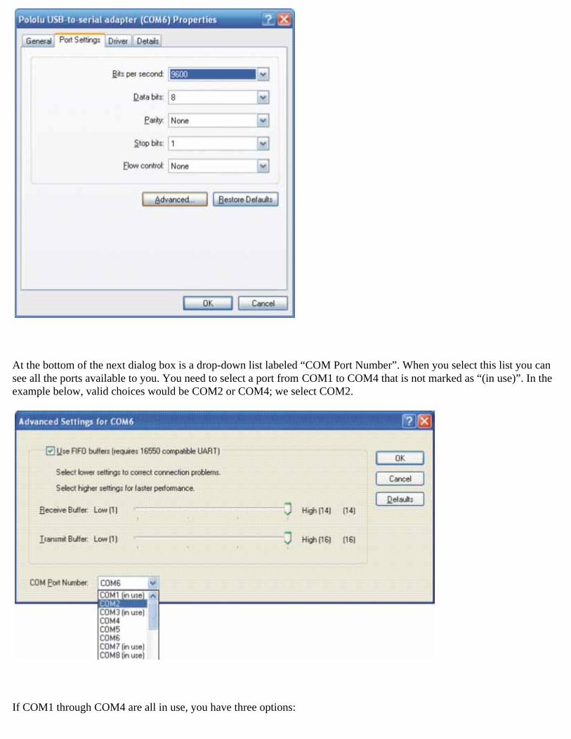
At the bottom of the next dialog box is a drop-down list labeled “COM Port Number”. When you select this list you cansee all the ports available to you. You need to select a port from COM1 to COM4 that is not marked as “(in use)”. In theexample below, valid choices would be COM2 or COM4; we select COM2.
If COM1 through COM4 are all in use, you have three options:
1) find a way to free up one of those ports by disconnecting something
2) find another terminal program that will let you send binary files to ports greater than COM4
3) reassign your programmer to an “in use” port that you know nothing is currently connected to.
Note that if you choose option 3, you might run into problems in the future if you ever simultaneously connect yourprogrammer and the other device that is configured to use that port. Once you have chosen your new port, click OK onboth the Advanced and Properties windows and close the Computer Management window. If you re-open ComputerManagement window, you should see your serial adapter mapped to your newly selected port.
8.b. Uploading the New Firmware
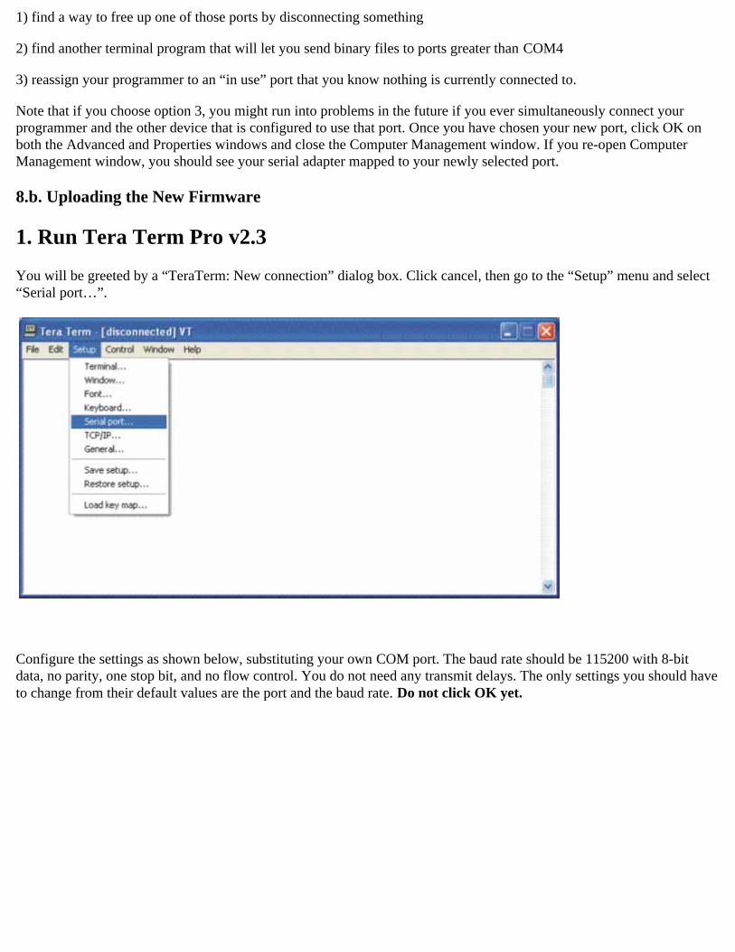
1. Run Tera Term Pro v2.3
You will be greeted by a “TeraTerm: New connection” dialog box. Click cancel, then go to the “Setup” menu and select“Serial port…”.
Configure the settings as shown below, substituting your own COM port. The baud rate should be 115200 with 8-bitdata, no parity, one stop bit, and no flow control. You do not need any transmit delays. The only settings you should haveto change from their default values are the port and the baud rate. Do not click OK yet.

2. Enter the programmer’s firmware update mode
When you connect your programmer to your computer via the USB cable, you should see both the red and green status LEDs light for approximately five seconds. During this time, the programmer is waiting for the proper input sequencethat will put it into firmware update mode. The procedure for entering firmware update mode is as follows:
Bring up the Tera Term serial port setup dialog as described in part 1 above, but do not connect yet.Plug your programmer into your computer via the USB cable and wait for the green USB status LED to light. Itusually takes around 0.5 s for the USB connection to be established.Once the green USB status LED is lit and while both red and green programmer status LEDs are still lit, click OKin the Tera Term serial port setup dialog to establish a connection and type fwbootload. This string must be in alllowercase. With every successfully entered letter, the 5-second timer resets, so the biggest difficulty is typing thatfirst “f” before the first 5-second period expires and the two status LEDs turn off.
As you type the string, you will see the uppercase version of the letters you type echoed back, so as you type“fwbootload”, you will see “FWBOOTLOAD”. If you enter a letter incorrectly, a ”?” will be echoed back to youand both status LEDs will turn off immediately. If this happens you will need to disconnect from Tera Term,unplug your programmer, and repeat the process again.
If you enter the string successfully, you will see the bootloader version number echoed back to you (probably“1.2”). Note that this bootloader version number is not the same as the the programmer’s firmware version number.This version number is the version of the small piece of code (called a “bootloader”) that is reprogramming theprogrammer’s flash.
At this point you can type x to exit firmware upgrade mode or s to load the new firmware. If you type s, there will be a brief delay as the current firmware is erased, after which you will see S echoed back. Now the programmer iswaiting for you to upload a binary data file containing the new firmware. This data file should have a .pgmextension.
3. Loading the new firmware
From the “File” menu, select “Send file….”
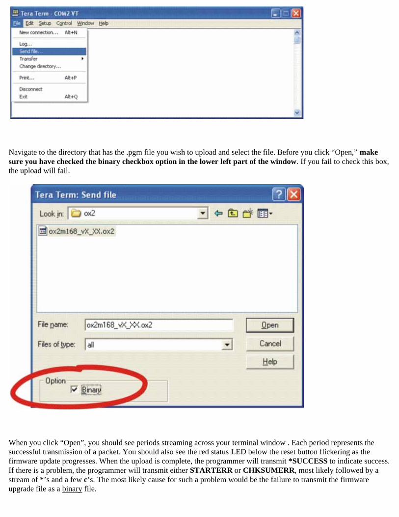
Navigate to the directory that has the .pgm file you wish to upload and select the file. Before you click “Open,” make sure you have checked the binary checkbox option in the lower left part of the window. If you fail to check this box,the upload will fail.
When you click “Open”, you should see periods streaming across your terminal window . Each period represents thesuccessful transmission of a packet. You should also see the red status LED below the reset button flickering as thefirmware update progresses. When the upload is complete, the programmer will transmit *SUCCESS to indicate success.If there is a problem, the programmer will transmit either STARTERR or CHKSUMERR, most likely followed by a stream of *’s and a few c’s. The most likely cause for such a problem would be the failure to transmit the firmwareupgrade file as a binary file.
![Pololu - Pololu USB AVR Programmer User's Guide · PDF filePololu USB AVR Programmer User's Guide 1. ... avr_development_bundle_110524.exe?file_id=0J481] ... settings of your programmer](https://img.pdfslide.net/doc/110x75/5aad6b997f8b9a59658e4476/pololu-pololu-usb-avr-programmer-users-guide-usb-avr-programmer-users-guide.jpg)