Embed Size (px)
Citation preview

Polybutylene Plumbing System
Installation Guidelines
®
2
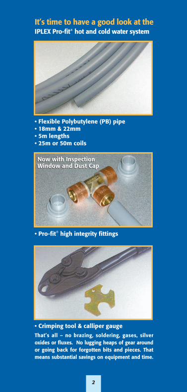
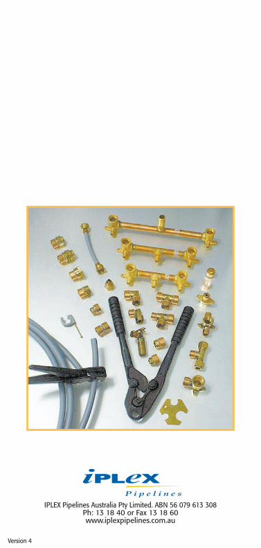
It’s time to have a good look at theIPLEX Pro-fit® hot and cold water system
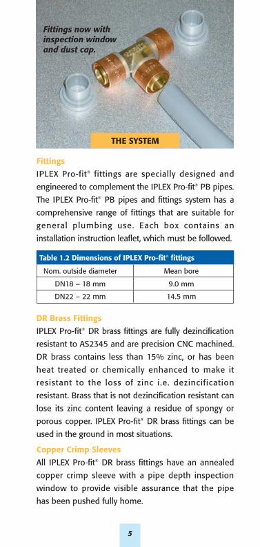
• Crimping tool & calliper gauge
That’s all – no brazing, soldering, gases, silveroxides or fluxes. No lugging heaps of gear aroundor going back for forgotten bits and pieces. Thatmeans substantial savings on equipment and time.
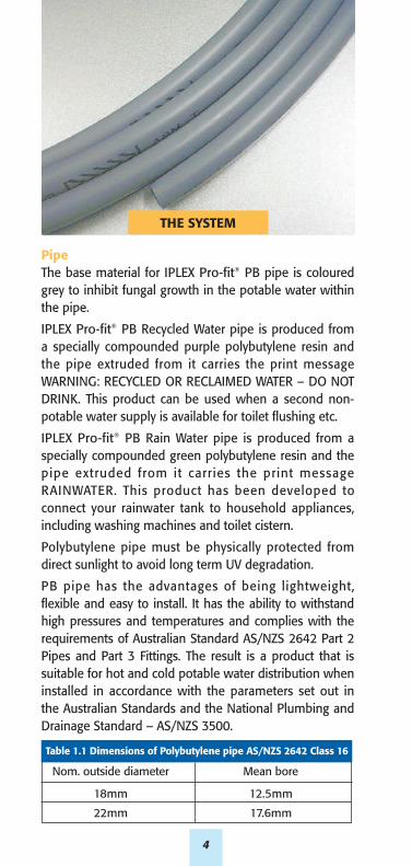
• Pro-fit® high integrity fittings
• Flexible Polybutylene (PB) pipe• 18mm & 22mm • 5m lengths • 25m or 50m coils
Now with InspectionWindow and Dust CapNow with InspectionWindow and Dust Cap

INTRODUCTION
This technical manual details features and installation
aspects of the three ranges of IPLEX Pro-fit® Polybutylene
(PB) pipes and fittings system:
IPLEX Pro-fit® PB Hot and Cold Water
– Grey Pipe
IPLEX Pro-fit® PB Recycled Water
– Purple Pipe
Fittings and tools for all three pipe systems are identical.
The IPLEX Pro-fit® system meets the equirements of
Australian Standard AS/NZS 2642 Parts 2 & 3. The
system is intended for use by licensed plumbing
tradesmen who are used to working in accordance with
accepted plumbing practice and the Australian/New
Zealand National Plumbing and Drainage Standard
AS/NZS 3500.
IPLEX Pro-fit® offers an integrated system that has been
well proven around the world and throughout Australia.
IPLEX Pro-fit® offers a system that is flexible enough to
be bent by hand, is extremely light weight, offers
corrosion resistance, and eliminates water hammer
noise. In particular, no brazing or soldering is necessary.
When installed by a licensed tradesman, the system has
proven to be both high quality and economical to use.
3
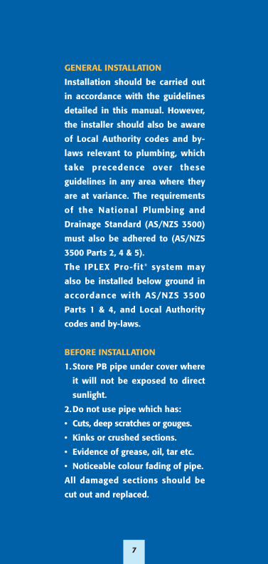
PipeThe base material for IPLEX Pro-fit® PB pipe is colouredgrey to inhibit fungal growth in the potable water withinthe pipe.
IPLEX Pro-fit® PB Recycled Water pipe is produced froma specially compounded purple polybutylene resin andthe pipe extruded from it carries the print messageWARNING: RECYCLED OR RECLAIMED WATER – DO NOTDRINK. This product can be used when a second non-potable water supply is available for toilet flushing etc.
IPLEX Pro-fit® PB Rain Water pipe is produced from aspecially compounded green polybutylene resin and thepipe extruded from it carries the print messageRAINWATER. This product has been developed toconnect your rainwater tank to household appliances,including washing machines and toilet cistern.
Polybutylene pipe must be physically protected fromdirect sunlight to avoid long term UV degradation.
PB pipe has the advantages of being lightweight, flexible and easy to install. It has the ability to withstandhigh pressures and temperatures and complies with therequirements of Australian Standard AS/NZS 2642 Part 2Pipes and Part 3 Fittings. The result is a product that issuitable for hot and cold potable water distribution wheninstalled in accordance with the parameters set out inthe Australian Standards and the National Plumbing andDrainage Standard – AS/NZS 3500.
4
Table 1.1 Dimensions of Polybutylene pipe AS/NZS 2642 Class 16
Nom. outside diameter Mean bore
18mm 12.5mm
22mm 17.6mm
THE SYSTEM
5
Fittings
IPLEX Pro-fit® fittings are specially designed and
engineered to complement the IPLEX Pro-fit® PB pipes.
The IPLEX Pro-fit® PB pipes and fittings system has a
comprehensive range of fittings that are suitable for
general plumbing use. Each box contains an
installation instruction leaflet, which must be followed.
DR Brass Fittings
IPLEX Pro-fit® DR brass fittings are fully dezincification
resistant to AS2345 and are precision CNC machined.
DR brass contains less than 15% zinc, or has been
heat treated or chemically enhanced to make it
resistant to the loss of zinc i.e. dezincification
resistant. Brass that is not dezincification resistant can
lose its zinc content leaving a residue of spongy or
porous copper. IPLEX Pro-fit® DR brass fittings can be
used in the ground in most situations.
Copper Crimp Sleeves
All IPLEX Pro-fit® DR brass fittings have an annealed
copper crimp sleeve with a pipe depth inspection
window to provide visible assurance that the pipe
has been pushed fully home.
THE SYSTEM
Table 1.2 Dimensions of IPLEX Pro-fit® fittings
Nom. outside diameter Mean bore
DN18 – 18 mm 9.0 mm
DN22 – 22 mm 14.5 mm
Fittings now withinspection windowand dust cap.

6
Crimping Tools
The crimping tools are precision instrumentsengineered to ensure a simple, effective joint. Theprinciple of this jointing method has been wellproven in many engineering applications in Australia.It is extensively used around the world for gas, hotand cold plumbing and in-floor heating.
With crimping tools, care should be taken to ensurethat moving parts are not damaged. Refer toindividual tool instructions for maintenance andcorrect use. Calliper gauges are supplied with alltools to check that the copper ring has been properlycrimped. Only use the correct IPLEX tools to crimpthe IPLEX Pro-fit® PB pipes and fittings system.
Do not attempt to crimp the IPLEX Pro-fit® systemwith any other type of tool. IPLEX Pro-fit® PB pipe andfittings offer the plumber an integrated system thathas been well proven around the world.
Some of the advantages are:
• Light weight and flexible – for ease of assembly.
• Simple jointing system – quick assembly, high integrity.
• No brazing, soldering, gases, silver solders or fluxes.
• No electrolysis.
• Corrosion resistant – for aggressive conditions.
• Little resale value – minimises theft.
• Long lengths, therefore less joints and fittings – forease of assembly.
• Tamper proof jointing system – once the system iscrimped it cannot be pulled apart.
• Virtually eliminates water hammer noise – reduced callbacks.
ADVANTAGES
GENERAL INSTALLATION
Installation should be carried out
in accordance with the guidelines
detailed in this manual. However,
the installer should also be aware
of Local Authority codes and by-
laws relevant to plumbing, which
take precedence over these
guidelines in any area where they
are at variance. The requirements
of the National Plumbing and
Drainage Standard (AS/NZS 3500)
must also be adhered to (AS/NZS
3500 Parts 2, 4 & 5).
The IPLEX Pro-fit® system may
also be installed below ground in
accordance with AS/NZS 3500
Parts 1 & 4, and Local Authority
codes and by-laws.
BEFORE INSTALLATION
1.Store PB pipe under cover where
it will not be exposed to direct
sunlight.
2.Do not use pipe which has:
• Cuts, deep scratches or gouges.
• Kinks or crushed sections.
• Evidence of grease, oil, tar etc.
• Noticeable colour fading of pipe.
All damaged sections should be
cut out and replaced.
7
8
JOINTING PROCEDURES
Crimped connections
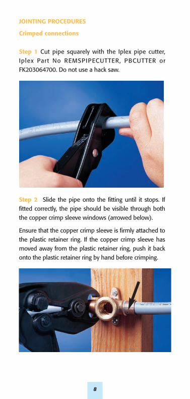
Step 1 Cut pipe squarely with the Iplex pipe cutter,Iplex Part No REMSPIPECUTTER, PBCUTTER orFK203064700. Do not use a hack saw.
Step 2 Slide the pipe onto the fitting until it stops. Iffitted correctly, the pipe should be visible through boththe copper crimp sleeve windows (arrowed below).
Ensure that the copper crimp sleeve is firmly attached tothe plastic retainer ring. If the copper crimp sleeve hasmoved away from the plastic retainer ring, push it backonto the plastic retainer ring by hand before crimping.
JOINTING PROCEDURES continued
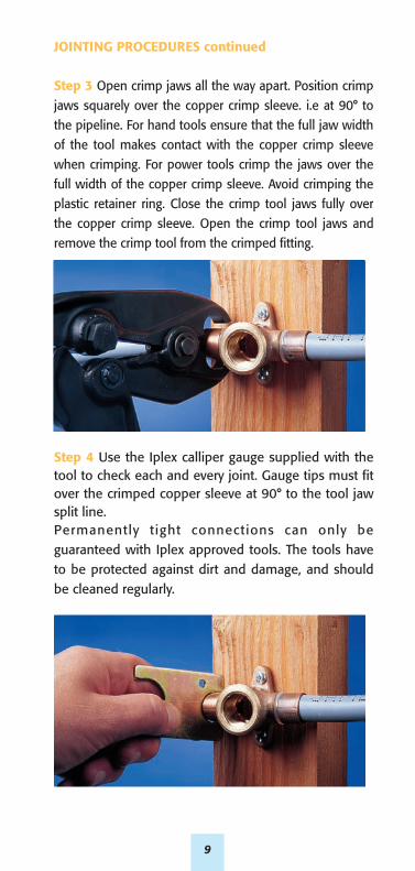
Step 3 Open crimp jaws all the way apart. Position crimpjaws squarely over the copper crimp sleeve. i.e at 90° tothe pipeline. For hand tools ensure that the full jaw widthof the tool makes contact with the copper crimp sleevewhen crimping. For power tools crimp the jaws over thefull width of the copper crimp sleeve. Avoid crimping theplastic retainer ring. Close the crimp tool jaws fully overthe copper crimp sleeve. Open the crimp tool jaws andremove the crimp tool from the crimped fitting.
Step 4 Use the Iplex calliper gauge supplied with thetool to check each and every joint. Gauge tips must fitover the crimped copper sleeve at 90° to the tool jawsplit line.Permanently tight connections can only beguaranteed with Iplex approved tools. The tools haveto be protected against dirt and damage, and shouldbe cleaned regularly.
9
JOINTING PROCEDURES Continued
Under-crimping
Under-crimping (i.e. when the gauge will not pass
over copper ring) can occur when:
1. The crimping tool has not been completely closed.
2. The crimping tool is out of adjustment
(readjustment should be made in accordance
with the instructions supplied with the tool).
How to avoid a faulty connection
The IPLEX Pro-fit® pipes and fittings system is simple
and effective to use when executed in accordance
with the jointing procedures. However, if sufficient
care is not taken, the consequences can be improper
sealing, and a potential for leaks.
The most likely causes of faulty connections are:
1. Copper crimp sleeve has moved away from the
body of the fitting.
2. The crimping tool has not been centred over the
copper crimp sleeve, and thus the sleeve has only
been partially crimped.
3. The pipe has not been pushed fully home on to
the fitting when the crimp was made.
4. Pipe has not been cut squarely.
5. Tools are poorly maintained or damaged.
If an incorrect joint is detected :
• Cut out the defective joint and replace with new
IPLEX Pro-fit® fitting.
If the pipe is kinked or damaged:
• The faulty section of the pipe should be replaced.
10
11
JOINTING PROCEDURES Continued
Iplex PRO-FIT® PB pipe to copper pipe, steel pipesystems or appliances.Threaded fittings – brass or copper threaded fittingsshould not be used with other non-metallic threadedfittings. Use an approved sealant to seal all threadedfittings.
• When using brazing tails to connect copper pipeor metal fittings to IPLEX Pro-fit® PB pipe, alwaysbraze the brazing tail to the copper pipe or metalfittings first and allow it to cool before assemblingthe IPLEX Pro-fit® PB pipe.
At least four ribs should be shown on the brazing tailsto allow for an effective joint to be made. It isrecommended that silver brazing alloys be used andthat all flux deposits are removed once the joint hasbeen made. Excessive heat can damage IPLEX Pro-fit®
PB pipes. When brazing copper pipes or fittings nearIPLEX Pro-fit® PB pipes it is recommended a damp ragbe used to protect the pipes.
Pipe bending
Due to the pipe’s inherent flexibility and its availability
in 50m coils for 18mm and 22mm pipe, polybutylene
can be bent easily around obstructions or through
studs and plates with minimum use of fittings. Care
should be taken not to kink or damage the pipe. It is
recommended that the minimum bending radius be
10 times the outside diameter of the pipe. If this is
not possible an IPLEX Pro-fit® elbow should be used.
If for any reason the pipe is kinked or damaged, the
faulty section should be replaced.
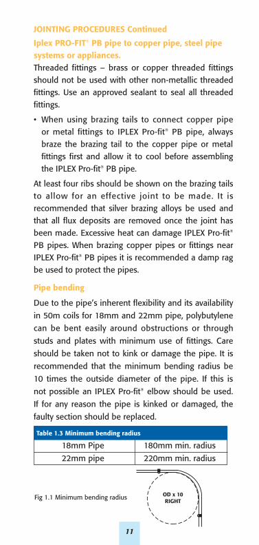
Table 1.3 Minimum bending radius
18mm Pipe 180mm min. radius
22mm pipe 220mm min. radius
Fig 1.1 Minimum bending radius OD x 10RIGHT
INSTALLATION
Hot water installation
1. It is recommended that the IPLEX Pro-fit® system be
installed in accordance with the manufacturers
installation requirements, AS/NZS 3500 Part 4 and
any local by-laws with particular reference to the
pressure and temperature relationship as described
in AS / NZS 2642 and detailed in Table 1.4.
2. The valves used in the installation of water heaters
should comply with the requirements as laid out in
AS/NZS 3500 Part 4, Tables 4.1 & 4.2.
The required set pressure of valves i.e. expansion
control valves and inlet pressure control valves shall
be:-
a. as specified by the water heater manufacturer; or
b. determined from the set pressure of the
temperature and pressure relief valve supplied
by the water heater manufacturer, with reference
to AS/NZS 3500 Part 4, Table 4.2.
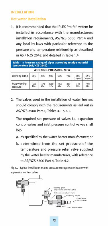
Fig 1.2 Typical installation mains pressure storage water heater with
expansion control valve
WORKING PRESSURE. MPa
Working temp 20C 40C 50C 60C 70C 80C 95C(25 years) (10 years)
Max working 1600 1370 1200 1050 880 740 490pressure kPa kPa kPa kPa kPa kPa kPa
Table 1.4 Pressure rating of pipes according to pipe material temperature (AS/NZS 2642)
12
Easing gearExpansion control valveIn line non-return valve
Isolating valveCold water supply line
Line strainer
INSTALLATION Continued
3. The use of tempering valves is required in some
capital cities and provincial areas. Check with
your Local Authority.
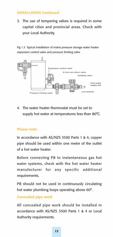
Fig 1.3 Typical installation of mains pressure storage water heater
expansion control valve and pressure limiting valve
4. The water heater thermostat must be set to
supply hot water at temperatures less than 80°C.
Please note:
In accordance with AS/NZS 3500 Parts 1 & 4, copper
pipe should be used within one metre of the outlet
of a hot water heater.
Before connecting PB to instantaneous gas hot
water systems, check with the hot water heater
manufacturer for any specific additional
requirements.
PB should not be used in continuously circulating
hot water plumbing loops operating above 60°.
Concealed pipe work
All concealed pipe work should be installed in
accordance with AS/NZS 3500 Parts 1 & 4 or Local
Authority requirements.
Expansion control valve
In line non-return valveIsolating valve
Cold water supply line
Line strainerPressure limiting valve
13
INSTALLATION Continued
Timber framework
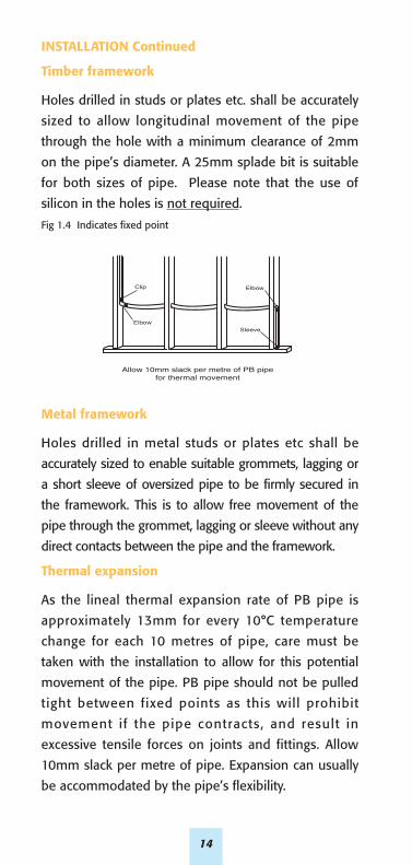
Holes drilled in studs or plates etc. shall be accurately
sized to allow longitudinal movement of the pipe
through the hole with a minimum clearance of 2mm
on the pipe’s diameter. A 25mm splade bit is suitable
for both sizes of pipe. Please note that the use of
silicon in the holes is not required.
Fig 1.4 Indicates fixed point
Metal framework
Holes drilled in metal studs or plates etc shall be
accurately sized to enable suitable grommets, lagging or
a short sleeve of oversized pipe to be firmly secured in
the framework. This is to allow free movement of the
pipe through the grommet, lagging or sleeve without any
direct contacts between the pipe and the framework.
Thermal expansion
As the lineal thermal expansion rate of PB pipe is
approximately 13mm for every 10°C temperature
change for each 10 metres of pipe, care must be
taken with the installation to allow for this potential
movement of the pipe. PB pipe should not be pulled
tight between fixed points as this will prohibit
movement if the pipe contracts, and result in
excessive tensile forces on joints and fittings. Allow
10mm slack per metre of pipe. Expansion can usually
be accommodated by the pipe’s flexibility.
Allow 10mm slack per metre of PB pipefor thermal movement
Elbow
Sleeve
Clip
Elbow
14
15
INSTALLATION Continued
Chases, ducts or conduits
As per AS/NZS 3500 Parts 1 & 4 or Local Authority
requirements.
Pipes in chases shall be continuously wrapped with
an impermeable flexible material.
Ducts shall be fitted with removable covers.
Pipes embedded in walls or floors shall comply with
the requirements of the appropriate building
authority and/or local regulations.
Under concrete slabs
PB pipe may be installed under concrete slabs in
accordance with AS/NZS 3500 Parts 1 & 4, or Local
Authority requirements.
When PB penetrates the slab it shall be at right
angles to the surface of the slab and shall be lagged
with an impermeable, flexible plastics material of not
less than 6mm thickness for the full depth of the
slab penetration ie PVC conduit or pressure pipe.
Clipping and supports
The use of pipe clips should be in accordance with
AS/NZS 3500 Parts 1 & 4 and in keeping with good
plumbing practice. The following table is based on
AS/NZS 3500.
Corrosive environment
As per the requirements of AS/NZS 3500 and/or
Local Authority or Regulatory requirements, PB pipe
and fittings installed in potentially corrosive
environment must be protected, i .e. marine
environment.
16
INSTALLATION Continued
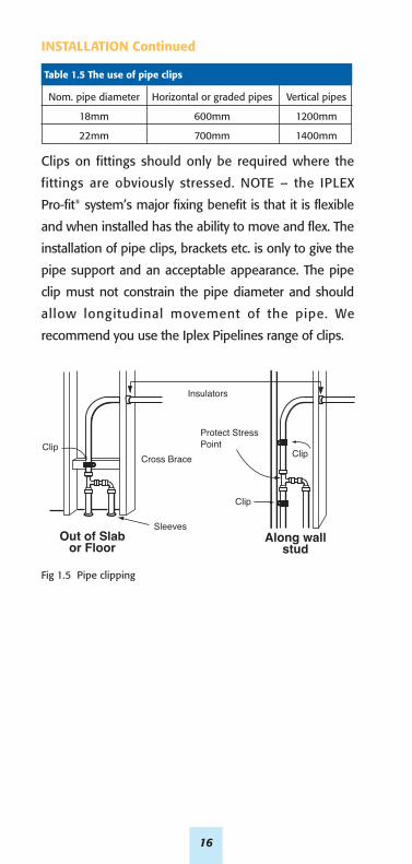
Clips on fittings should only be required where the
fittings are obviously stressed. NOTE – the IPLEX
Pro-fit® system’s major fixing benefit is that it is flexible
and when installed has the ability to move and flex. The
installation of pipe clips, brackets etc. is only to give the
pipe support and an acceptable appearance. The pipe
clip must not constrain the pipe diameter and should
allow longitudinal movement of the pipe. We
recommend you use the Iplex Pipelines range of clips.
Clip Clip
Clip
Sleeves
Insulators
Cross Brace
Out of Slabor Floor
Along wallstud
Protect StressPoint
Table 1.5 The use of pipe clips
Nom. pipe diameter Horizontal or graded pipes Vertical pipes
18mm 600mm 1200mm
22mm 700mm 1400mm
Fig 1.5 Pipe clipping
17
Tempering ValveHot water
Tempered water
Line Strainer& Check Valve
LEGEND: H-HotC-ColdM-Mix
Coldsupply
C
H
M
SolarPanel
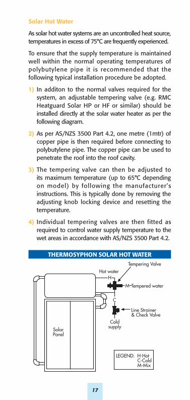
Solar Hot Water
As solar hot water systems are an uncontrolled heat source,temperatures in excess of 75°C are frequently experienced.
To ensure that the supply temperature is maintainedwell within the normal operating temperatures ofpolybutylene pipe it is recommended that thefollowing typical installation procedure be adopted.
1) In additon to the normal valves required for thesystem, an adjustable tempering valve (e.g. RMCHeatguard Solar HP or HF or similar) should beinstalled directly at the solar water heater as per thefollowing diagram.
2) As per AS/NZS 3500 Part 4.2, one metre (1mtr) ofcopper pipe is then required before connecting topolybutylene pipe. The copper pipe can be used topenetrate the roof into the roof cavity.
3) The tempering valve can then be adjusted toits maximum temperature (up to 65°C dependingon model) by following the manufacturer’sinstructions. This is typically done by removing theadjusting knob locking device and resetting thetemperature.
4) Individual tempering valves are then fitted asrequired to control water supply temperature to thewet areas in accordance with AS/NZS 3500 Part 4.2.
THERMOSYPHON SOLAR HOT WATER

18
TESTING & INSPECTION PROCEEDURES
Testing procedures should be as per the
requirements of AS/NZS 3500 part 1,4 & 5 and/or
any Local Authority or Regulatory requirements.
While the system is under test, all joints and fittings
should be inspected for leaks and to ensure that
the pipe has been fitted correctly and crimped
in accordance with IPLEX Pro-fit® Polybutylene
Plumbing System Installation Guidelines.
FIRE & EXCESSIVE HEAT
Keep PB pipe a minimum of 500mm from sources of
high heat such as heating appliances, flues, vents etc.
Keep PB pipe 1500mm from slow combustion type
stoves, vents and flues used to heat domestic hot
water, wet back boilers etc.
PB pipe should not be positioned closer than 150mm
to gas or central heating vents, nor located in any
confined space containing appliance vents or flues.
PB pipe and fittings are designed to meet the normal
operating temperatures of domestic hot and cold
water, however, in the case of uncontrolled heat
input such as slow combustion stoves or room
heaters with water heating coils, wet back boilers or
the like, and in the interest of safe water temperature
to protect the user, tempering valves must be
considered. The primary flow and returns on these
type of appliances should not be installed in PB pipe
and fittings.
Where PB pipe is installed and penetrates fire
resistant construction, the fire resistant integrity of
the construction must be retained. Refer to the local
building code.
19
PROTECTION
If a system is to be exposed to sunlight beyond
normal construction periods, the pipe should be
protected from sunlight (UV) damage.
Lineal thermal expansion rate for PB pipe is
approximately 13mm/10°C temperature change for
each 10 metres of pipe.
Leave 300mm minimum space between PB pipe and
recessed electric light fittings, as light fittings are
normally changed on a regular basis.
LIMITATIONS OF PB PIPE
When:
• Used as part of a water meter assembly or vertical riser.
• Used beyond the inlet stop valve to any water heater.
• Used where subject to direct sunlight.
• Used in areas subject to contaminat ion by
petroleum products.
• Used within one metre of the outlet of, or between
isolation valve and inlet of any water heater.
• Water temperature / pressure combinations should
not exceed the limitations as given in Table 1.4.
• Used on continuously circulating hot water loops
operating above 60°C.
• Buried underground and subject to flooding with a
termite treatment.
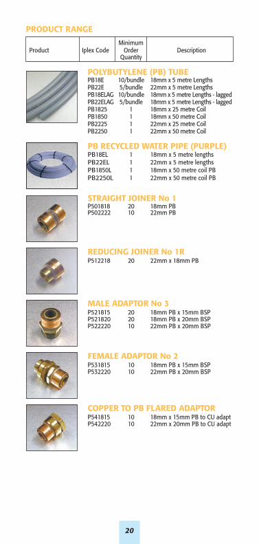
PRODUCT RANGE
MinimumProduct Iplex Code Order Description
Quantity
POLYBUTYLENE (PB) TUBEPB18E 10/bundle 18mm x 5 metre LengthsPB22E 5/bundle 22mm x 5 metre LengthsPB18ELAG 10/bundle 18mm x 5 metre Lengths - laggedPB22ELAG 5/bundle 18mm x 5 metre Lengths - laggedPB1825 1 18mm x 25 metre CoilPB1850 1 18mm x 50 metre CoilPB2225 1 22mm x 25 metre CoilPB2250 1 22mm x 50 metre Coil
PB RECYCLED WATER PIPE (PURPLE)PB18EL 1 18mm x 5 metre lengthsPB22EL 1 22mm x 5 metre lengthsPB1850L 1 18mm x 50 metre coil PBPB2250L 1 22mm x 50 metre coil PB
STRAIGHT JOINER No 1P501818 20 18mm PBP502222 10 22mm PB
REDUCING JOINER No 1RP512218 20 22mm x 18mm PB
MALE ADAPTOR No 3P521815 20 18mm PB x 15mm BSP P521820 20 18mm PB x 20mm BSP P522220 10 22mm PB x 20mm BSP
FEMALE ADAPTOR No 2P531815 10 18mm PB x 15mm BSP P532220 10 22mm PB x 20mm BSP
COPPER TO PB FLARED ADAPTORP541815 10 18mm x 15mm PB to CU adaptP542220 10 22mm x 20mm PB to CU adapt
20
21
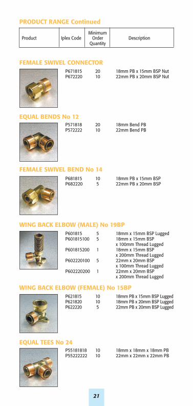
PRODUCT RANGE Continued
MinimumProduct Iplex Code Order Description
Quantity
FEMALE SWIVEL CONNECTORP671815 20 18mm PB x 15mm BSP Nut P672220 10 22mm PB x 20mm BSP Nut
EQUAL BENDS No 12P571818 20 18mm Bend PBP572222 10 22mm Bend PB
FEMALE SWIVEL BEND No 14P681815 10 18mm PB x 15mm BSP P682220 5 22mm PB x 20mm BSP
WING BACK ELBOW (MALE) No 19BPP601815 5 18mm x 15mm BSP LuggedP601815100 5 18mm x 15mm BSP
x 100mm Thread LuggedP601815200 1 18mm x 15mm BSP
x 200mm Thread LuggedP602220100 5 22mm x 20mm BSP
x 100mm Thread Lugged P602220200 1 22mm x 20mm BSP
x 200mm Thread Lugged
WING BACK ELBOW (FEMALE) No 15BPP621815 10 18mm PB x 15mm BSP LuggedP621820 10 18mm PB x 20mm BSP LuggedP622220 5 22mm PB x 20mm BSP Lugged
EQUAL TEES No 24P55181818 10 18mm x 18mm x 18mm PBP55222222 10 22mm x 22mm x 22mm PB
22
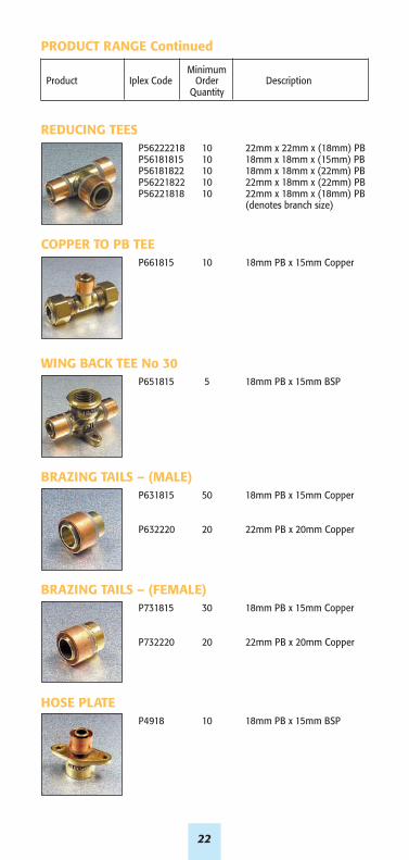
PRODUCT RANGE Continued
MinimumProduct Iplex Code Order Description
Quantity
REDUCING TEESP56222218 10 22mm x 22mm x (18mm) PBP56181815 10 18mm x 18mm x (15mm) PBP56181822 10 18mm x 18mm x (22mm) PBP56221822 10 22mm x 18mm x (22mm) PBP56221818 10 22mm x 18mm x (18mm) PB
(denotes branch size)
COPPER TO PB TEEP661815 10 18mm PB x 15mm Copper
WING BACK TEE No 30P651815 5 18mm PB x 15mm BSP
BRAZING TAILS – (MALE)P631815 50 18mm PB x 15mm Copper
P632220 20 22mm PB x 20mm Copper
BRAZING TAILS – (FEMALE)P731815 30 18mm PB x 15mm Copper
P732220 20 22mm PB x 20mm Copper
HOSE PLATEP4918 10 18mm PB x 15mm BSP
23
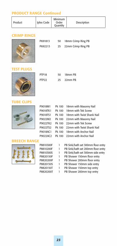
PRODUCT RANGE Continued
MinimumProduct Iplex Code Order Description
Quantity
CRIMP RINGSP691813 50 18mm Crimp Ring PB
P692213 25 22mm Crimp Ring PB
TEST PLUGSPTP18 50 18mm PB
PTP22 25 22mm PB
TUBE CLIPSP9018M1 Pk 100 18mm with Masonry NailP9018TK1 Pk 100 18mm with Tek ScrewP9018TS1 Pk 100 18mm with Twist Shank NailP9022M2 Pk 100 22mm with Masonry NailP9022TK2 Pk 100 22mm with Tek ScrewP9022TS2 Pk 100 22mm with Twist Shank NailP9018AC1 Pk 100 18mm with Anchor NailP9022AC2 Pk 100 22mm with Anchor Nail
BREECH RANGEP8810300F 1 PB Sink/bath set 300mm floor entryP8810200F 1 PB Sink/bath set 200mm floor entryP8810300S 1 PB Sink/bath set 300mm side entryP8820150F 1 PB Shower 150mm floor entryP8820200F 1 PB Shower 200mm floor entryP8820150S 1 PB Shower 150mm side entryP8820150T 1 PB Shower 150mm top entryP8820200T 1 PB Shower 200mm top entry
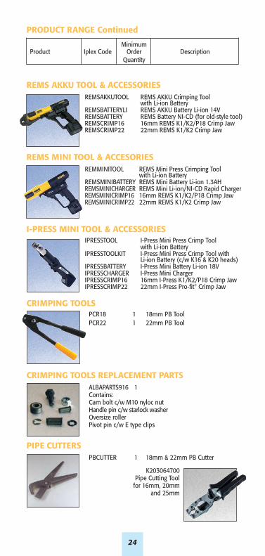
PRODUCT RANGE Continued
MinimumProduct Iplex Code Order Description
Quantity
REMS AKKU TOOL & ACCESSORIESREMSAKKUTOOL REMS AKKU Crimping Tool
with Li-ion BatteryREMSBATTERYLI REMS AKKU Battery Li-ion 14VREMSBATTERY REMS Battery NI-CD (for old-style tool)REMSCRIMP16 16mm REMS K1/K2/P18 Crimp JawREMSCRIMP22 22mm REMS K1/K2 Crimp Jaw
REMS MINI TOOL & ACCESORIESREMMINITOOL REMS Mini Press Crimping Tool
with Li-ion Battery REMSMINIBATTERY REMS Mini Battery Li-ion 1.3AHREMSMINICHARGER REMS Mini Li-ion/NI-CD Rapid ChargerREMSMINICRIMP16 16mm REMS K1/K2/P18 Crimp JawREMSMINICRIMP22 22mm REMS K1/K2 Crimp Jaw
I-PRESS MINI TOOL & ACCESSORIESIPRESSTOOL I-Press Mini Press Crimp Tool
with Li-ion BatteryIPRESSTOOLKIT I-Press Mini Press Crimp Tool with
Li-ion Battery (c/w K16 & K20 heads)IPRESSBATTERY I-Press Mini Battery Li-ion 18VIPRESSCHARGER I-Press Mini ChargerIPRESSCRIMP16 16mm I-Press K1/K2/P18 Crimp JawIPRESSCRIMP22 22mm I-Press Pro-fit® Crimp Jaw
CRIMPING TOOLSPCR18 1 18mm PB ToolPCR22 1 22mm PB Tool
CRIMPING TOOLS REPLACEMENT PARTSALBAPARTS916 1Contains:Cam bolt c/w M10 nyloc nutHandle pin c/w starlock washerOversize rollerPivot pin c/w E type clips
PIPE CUTTERSPBCUTTER 1 18mm & 22mm PB Cutter
K203064700Pipe Cutting Tool
for 16mm, 20mm and 25mm
24

25
CUSTOMER’S NEEDS CHANGE...PLUMBING MATERIALS CHANGEPB was first discovered in the early 1970’swhere it was quickly identified as an idealmaterial for hot and cold water plumbing.
It has gained wide acceptance because itmeets today’s needs in modern homes:• Mixer taps• Multiple high pressure appliances• Lots of variation in temperatures• Several bathrooms and ensues

DISCLAIMERThe information contained in thisdocument should serve as a guideonly and is subject to change withoutnotice. Iplex Pipelines Australia PtyLtd does not invite any person to actor rely upon such information andliability for such information isexcluded. In particular, as newtechnology is developed rapidly,product specifications, designs andcomponents may change and IplexPipelines Australia Pty Ltd reservesthe right at its discretion to makechanges as it see fit. The informationcontained in this document does notform part of the terms and conditionsof sale or constitute the descriptionof any goods to be supplied by IplexPipelines Australia Pty Ltd or itsdistributors. Before purchasinggoods, customers should sourcecurrent product information fromtheir distributor or seek expert adviceon their particular intended use andapplication for the product. No partof this document may be reproduced,stored in a retrieval system ortransmitted in any form, electronic,mechanical recording or otherwisewithout the prior written consent ofIplex Pipelines Australia Pty Ltd. Thedesigns, graphics, logos, tradenames,trademarks and other intellectualproperty contained in this documentare either owned by Iplex PipelinesAustralia Pty Ltd or used with thepermission of the owner or licensee,and must not be used without priorwritten consent. Copyright ©2013Iplex Pipelines Australia Pty Ltd. Allrights reserved.
26

27
WARRANTY
IPLEX Pipelines Australia Pty Limited. ABN 56 079 613 308Ph: 13 18 40 or Fax 13 18 60www.iplexpipelines.com.au
Version 4