Embed Size (px)
Citation preview
Polycom Headset Interface Adapter
User Manual
1725-33206-001 Rev. A
2
Trademark Information Polycom®, the Polycom logo design, SoundPoint® IP, SoundStation®, SoundStation VTX 1000®, ViaVideo®, ViewStation®, and Vortex® are registered trademarks of Polycom, Inc. Polycom HD Voice™, Conference Composer™, Global Management System™, ImageShare™, Instructor RP™, iPower™, MGC™, PathNavigator™, People+Content™, PowerCam™, Pro-Motion™, QSX™, ReadiManager™, Siren™, StereoSurround™, V2IU™, Visual Concert™, VS4000™, VSX®, SoundStructure™, and the industrial design of SoundStation are trademarks of Polycom, Inc. in the United States and various other countries. All other trademarks are the property of their respective owners.
Patent Information The accompanying product is protected by one or more U.S. and foreign patents and/or pending patent applications held by Polycom, Inc. Disclaimer Some countries, states, or provinces do not allow the exclusion or limitation of implied warranties or the limitation of incidental or consequential damages for certain products supplied to consumers, or the limitation of liability for personal injury, so the above limitations and exclusions may be limited in their application to you. When the implied warranties are not allowed to be excluded in their entirety, they will be limited to the duration of the applicable written warranty. This warranty gives you specific legal rights which may vary depending on local law. Copyright Notice
Permission is hereby granted, free of charge, to any person obtaining a copy of this software and associated documentation files (the “Software”), to deal in the Software without restriction, including without limitation the rights to use, copy, modify, merge, publish, distribute, sublicense, and/or sell copies of the Software, and to permit persons to whom the Software is furnished to do so, subject to the following conditions: The above copyright notice and this permission notice shall be included in all copies or substantial portions of the Software. THE SOFTWARE IS PROVIDED “AS IS”, WITHOUT WARRANTY OF ANY KIND, EXPRESS OR IMPLIED, INCLUDING BUT NOT LIMITED TO THE WARRANTIES OF MERCHANTABILITY, FITNESS FOR A PARTICULAR PURPOSE AND NONINFRINGEMENT. IN NO EVENT SHALL THE AUTHORS OR COPYRIGHT HOLDERS BE LIABLE FOR ANY CLAIM, DAMAGES OR OTHER LIABILITY, WHETHER IN AN ACTION OF CONTRACT, TORT OR OTHERWISE, ARISING FROM, OUT OF OR IN CONNECTION WITH THE SOFTWARE OR THE USE OR OTHER DEALINGS IN THE SOFTWARE.
© 2009, Polycom, Inc. All rights reserved. POLYCOM®, the Polycom "Triangles" logo and the names and marks associated with Polycom's products are trademarks and/or service marks of Polycom, Inc. and are registered and/or common law marks in the United States and various other countries. All other trademarks are property of their respective owners. No portion hereof may be reproduced or transmitted in any form or by any means, for any purpose other than the recipient's personal use, without the express written permission of Polycom.
Polycom Inc. 4750 Willow Road Pleasanton, CA 94588-2708 USA Every effort has been made to ensure that the information in this manual is accurate. Polycom, Inc. is not responsible for printing or clerical errors. Information in this document is subject to change without notice.
3
Introduction The Polycom Headset interface adapter is a Polycom® SoundStructure® accessory that enables the direct connection of a desktop telephone’s audio to a SoundStructure system. The headset interface adapter connects to the desktop phone via the phone’s headset interface and connects to the SoundStructure system using one analog input and one analog output channel.
In a typical user scenario, an installed room system has local microphones, a Polycom® HDX™ video codec, installed loudspeakers, and desktop phone that is used to communicate with remote telephone participants. With the headset adapter, a user may press the headset button on the desktop phone and send the desktop phone’s audio into the installed room via the SoundStructure system. The SoundStructure system will send the desktop phone audio to the HDX video codec and to the local room and use the installed microphones connected to send audio back to the remote telephone participant and any remote video participants.
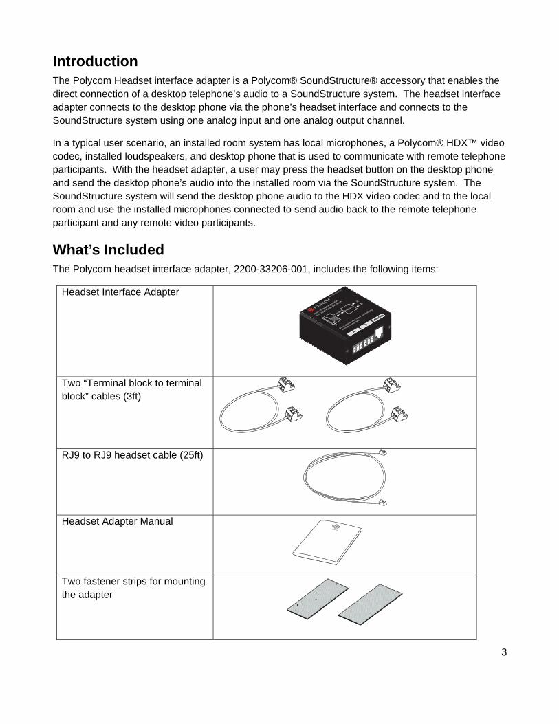
What’s Included The Polycom headset interface adapter, 2200-33206-001, includes the following items:
Headset Interface Adapter
Two “Terminal block to terminal block” cables (3ft)
RJ9 to RJ9 headset cable (25ft)
Headset Adapter Manual
Two fastener strips for mounting the adapter
4
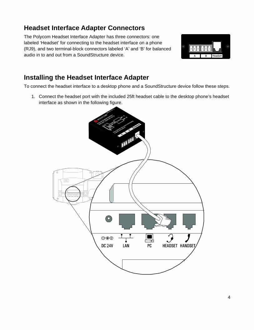
Headset Interface Adapter Connectors The Polycom Headset Interface Adapter has three connectors: one labeled ‘Headset’ for connecting to the headset interface on a phone (RJ9), and two terminal-block connectors labeled ‘A’ and ‘B’ for balanced audio in to and out from a SoundStructure device.
Installing the Headset Interface Adapter To connect the headset interface to a desktop phone and a SoundStructure device follow these steps.
1. Connect the headset port with the included 25ft headset cable to the desktop phone’s headset interface as shown in the following figure.
5
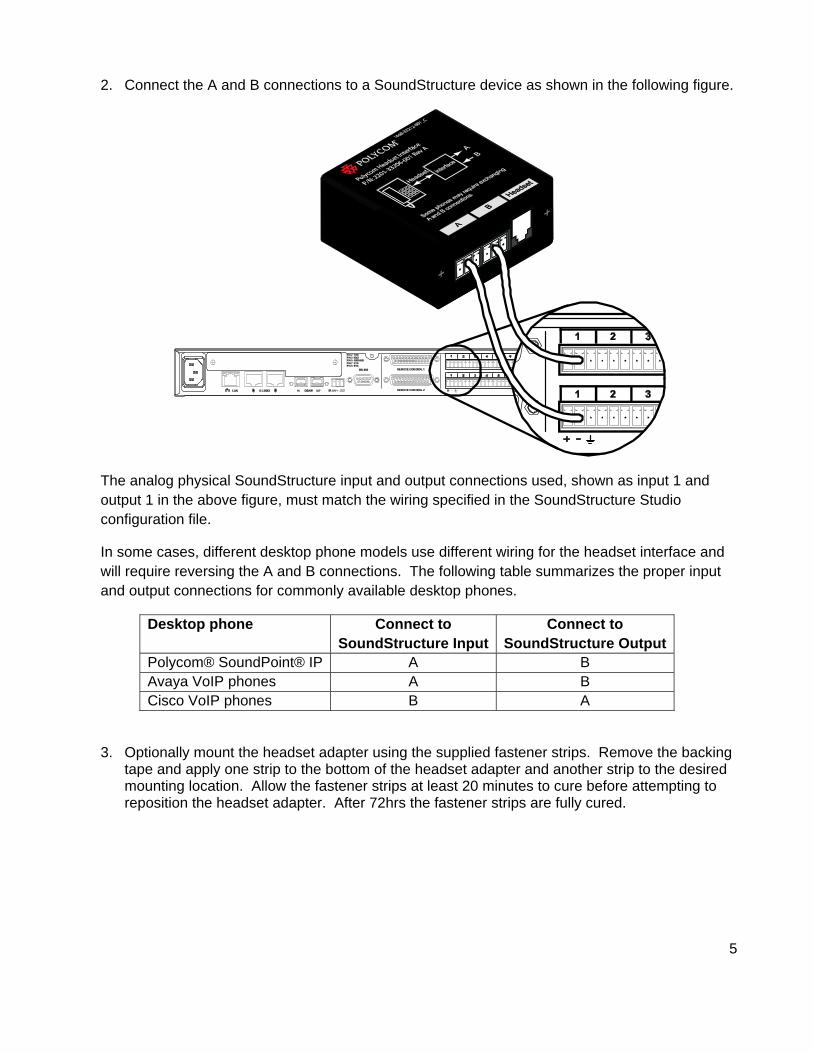
2. Connect the A and B connections to a SoundStructure device as shown in the following figure.
The analog physical SoundStructure input and output connections used, shown as input 1 and output 1 in the above figure, must match the wiring specified in the SoundStructure Studio configuration file.
In some cases, different desktop phone models use different wiring for the headset interface and will require reversing the A and B connections. The following table summarizes the proper input and output connections for commonly available desktop phones.
Desktop phone Connect to SoundStructure Input
Connect to SoundStructure Output
Polycom® SoundPoint® IP A B Avaya VoIP phones A B Cisco VoIP phones B A
3. Optionally mount the headset adapter using the supplied fastener strips. Remove the backing tape and apply one strip to the bottom of the headset adapter and another strip to the desired mounting location. Allow the fastener strips at least 20 minutes to cure before attempting to reposition the headset adapter. After 72hrs the fastener strips are fully cured.
6
Creating the SoundStructure Design File A SoundStructure configuration file must be loaded into the SoundStructure device that allows the signal from the headset interface to be used as an input to the SoundStructure and to allow the microphones connected to the SoundStructure and other signals to be sent to the headset interface. For information on how to use SoundStructure Studio, see the SoundStructure Design Guide that is available from the SoundStructure Studio Help menu. SoundStructure Studio may be downloaded from www.polycom.com .
A compatible SoundStructure configuration file may be created by considering the headset interface to be a video codec when designing a SoundStructure configuration file. The following steps show how to add the headset adapter to a SoundStructure Studio configuration file.
1. Design the SoundStructure configuration file for the application.
The configuration file should include all the microphones, any HDX video codecs, program audio, and the audio amplifiers that will be used as part of the design for the installed room. In this example, an HDX video codec is also included in the project.
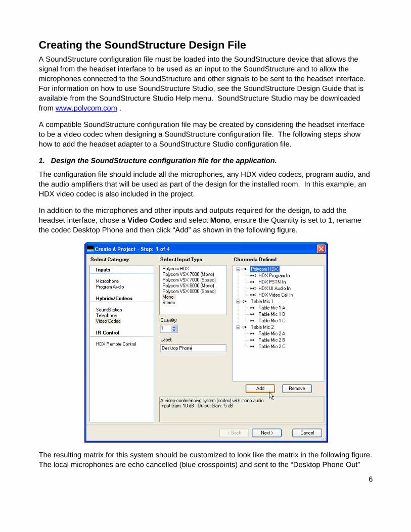
In addition to the microphones and other inputs and outputs required for the design, to add the headset interface, chose a Video Codec and select Mono, ensure the Quantity is set to 1, rename the codec Desktop Phone and then click “Add” as shown in the following figure.
The resulting matrix for this system should be customized to look like the matrix in the following figure. The local microphones are echo cancelled (blue crosspoints) and sent to the “Desktop Phone Out”
7
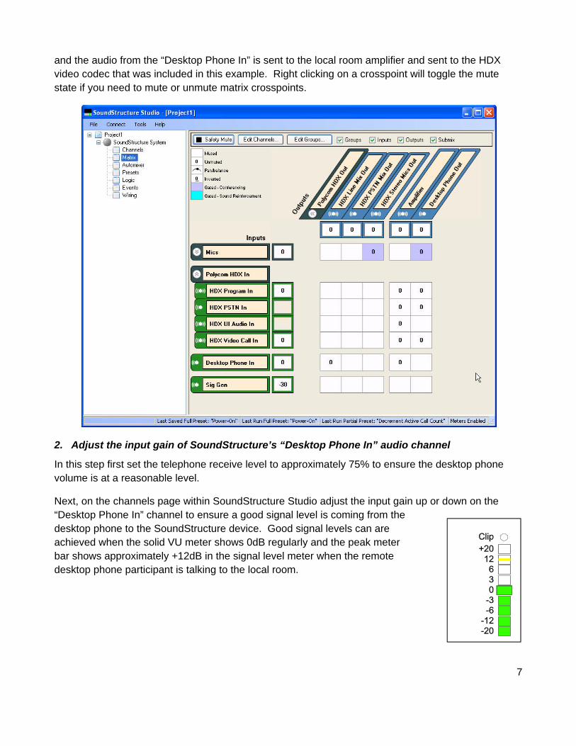
and the audio from the “Desktop Phone In” is sent to the local room amplifier and sent to the HDX video codec that was included in this example. Right clicking on a crosspoint will toggle the mute state if you need to mute or unmute matrix crosspoints.
2. Adjust the input gain of SoundStructure’s “Desktop Phone In” audio channel
In this step first set the telephone receive level to approximately 75% to ensure the desktop phone volume is at a reasonable level.
Next, on the channels page within SoundStructure Studio adjust the input gain up or down on the “Desktop Phone In” channel to ensure a good signal level is coming from the desktop phone to the SoundStructure device. Good signal levels can are achieved when the solid VU meter shows 0dB regularly and the peak meter bar shows approximately +12dB in the signal level meter when the remote desktop phone participant is talking to the local room.
8
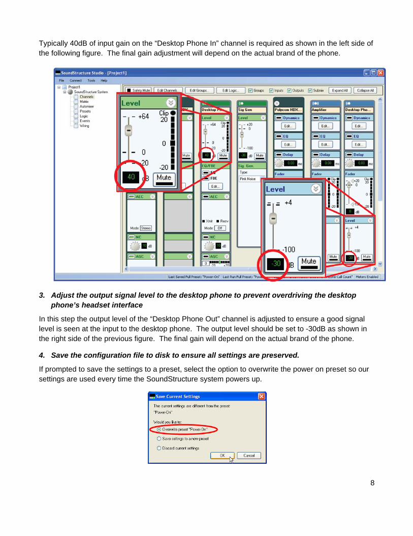
Typically 40dB of input gain on the “Desktop Phone In” channel is required as shown in the left side of the following figure. The final gain adjustment will depend on the actual brand of the phone.
3. Adjust the output signal level to the desktop phone to prevent overdriving the desktop phone’s headset interface
In this step the output level of the “Desktop Phone Out” channel is adjusted to ensure a good signal level is seen at the input to the desktop phone. The output level should be set to -30dB as shown in the right side of the previous figure. The final gain will depend on the actual brand of the phone.
4. Save the configuration file to disk to ensure all settings are preserved.
If prompted to save the settings to a preset, select the option to overwrite the power on preset so our settings are used every time the SoundStructure system powers up.
9
5. Customize the configuration to remove the headset sidetone
With telephone headsets and handsets, sidetone is an intentional echo of the local talker’s voice to the loudspeaker to provide feedback to the local talker that the system is operational. When using any installed system, the sidetone must be removed or it will be heard in the local room as an echo of the local talker’s voice.
If the sidetone on the headset interface may be turned off on the desktop phone, turn it off, and no further adjustments are required to the SoundStructure configuration file. If the sidetone of the headset cannot be disabled on the telephone, SoundStructure can remove the sidetone by creating a reference signal that contains any audio that will be sent to the desktop phone and using the SoundStructure echo canceller to remove the sidetone.
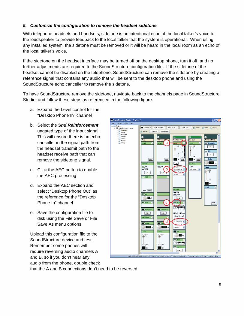
To have SoundStructure remove the sidetone, navigate back to the channels page in SoundStructure Studio, and follow these steps as referenced in the following figure.
a. Expand the Level control for the “Desktop Phone In” channel
b. Select the Snd Reinforcement ungated type of the input signal. This will ensure there is an echo canceller in the signal path from the headset transmit path to the headset receive path that can remove the sidetone signal.
c. Click the AEC button to enable the AEC processing
d. Expand the AEC section and select “Desktop Phone Out” as the reference for the “Desktop Phone In” channel
e. Save the configuration file to disk using the File Save or File Save As menu options
Upload this configuration file to the SoundStructure device and test. Remember some phones will require reversing audio channels A and B, so if you don’t hear any audio from the phone, double check that the A and B connections don’t need to be reversed.
10
Troubleshooting I need a longer cable from the headset adapter to my SoundStructure device.
You may build a longer cable for the balanced audio inputs and outputs to and from SoundStructure by using any two-conductor cable with a drain and terminating the cable in the same way the current “terminal block to terminal block” cables are terminated as a straight through connection.
The audio from the remote phone played into the installed room is too loud and sounds distorted
Different models of phones will require different input gain settings. Decrease the input gain on the channels page for the “Desktop Phone In” channel input on the SoundStructure device. Select a lower gain that does not exhibit audio clipping. Once you have adjusted the input gain, save your project using File Save or File Save As to ensure the settings are saved permanently in the SoundStructure project – both in the file and in the device if connected online.
The audio sent to the phone sounds too loud or too quiet
Adjust the output level on the Desktop Phone Out channel to be either lower or higher, respectively, so solve the problem. -30dB is the recommended level but the final level may vary by phone model.
I don’t hear the remote desktop phone participant’s audio in my installed room
Check the wiring page in SoundStructure Studio to see where the headset interface should be connected. Ensure the headset interface is physically plugged into the input and output shown on the wiring page.
If the headset interface is connected to the proper inputs and outputs and there is still no audio, ensure the Desktop Phone In channel is showing signal activity by looking at the signal meter on the Channels page in SoundStructure Studio. If there is no signal level there, make sure the input gain is set to +40dB. If you still see no signal level, try exchanging the connections on the A and B ports on the headset interface.
I hear myself in the installed room when I talk to the remote participants through the headset adapter
If the headset sidetone is not turned off on the desktop phone, the sidetone must be removed using an echo canceller channel on the SoundStructure system. Make sure there is a submix that contains all the audio that is being sent to the desktop phone and that submix is used as the echo canceller reference for the headset input to SoundStructure. Ensure that the ungated signal type of the headset input is set to ‘Snd Reinforcement’ to ensure the acoustic echo canceller is enabled for the ungated version of the input signal.
11
Limited Warranty Polycom warrants to the end user (‘‘Customer’’) that this product will be free from defects in workmanship and materials, under normal use and service, for one year from the date of purchase from Polycom or its authorized reseller. Polycom’s sole obligation under this express warranty shall be, at Polycom’s option and expense, to repair the defective product or part, deliver to Customer an equivalent product or part to replace the defective item, or if neither of the two foregoing options are reasonably available, Polycom may, on its sole discretion, refund to Customer the purchase price paid for the defective product. All products that are replaced will become the property of Polycom. Replacement products or parts may be new or reconditioned. Polycom warrants any replaced or repaired product or part for ninety (90) days from shipment, or the remainder of the initial warranty period, whichever is longer. Products returned to Polycom must be sent prepaid and packaged appropriately for safe shipment, and it is recommended that they be insured or sent by a method that provides for tracking of the package. Responsibility for loss or damage does not transfer to Polycom until the returned item is received by Polycom. The repaired or replaced item will be shipped to Customer, at Polycom’s expense, not later than thirty (30) days after Polycom receives the defective product, and Polycom will retain risk of loss or damage until the item is delivered to Customer.
EXCLUSIONS. Polycom will not be liable under this limited warranty if its testing and examination disclose that the alleged defect or malfunction in the product does not exist or results from: Failure to follow Polycom’s installation, operation, or maintenance instructions; Unauthorized product modification or alteration; Unauthorized use of common carrier communication services accessed through the product; Abuse, misuse, negligent acts or omissions of Customer and persons under Customer’s control; or; Acts of third parties, acts of God, accident, fire, lightening, power surges or outages, or other hazards.
WARRANTY EXCLUSIVE. IF A POLYCOM PRODUCT DOES NOT OPERATE AS WARRANTED ABOVE, CUSTOMER’S SOLE REMEDY FOR BREACH OF THAT WARRANTY SHALL BE REPAIR, REPLACEMENT, OR REFUND OF THE PURCHASE PRICE PAID, AT POLYCOM’S OPTION. TO THE FULL EXTENT ALLOWED BY LAW, THE FOREGOING WARRANTIES AND REMEDIES ARE EXCLUSIVE AND ARE IN LIEU OF ALL OTHER WARRANTIES, TERMS, OR CONDITIONS, EXPRESS OR IMPLIED, EITHER IN FACT OR BY OPERATION OF LAW, STATUTORY OR OTHERWISE, INCLUDING WARRANTIES, TERMS, OR CONDITIONS OF MERCHANTABILITY, FITNESS FOR A PARTICULAR PURPOSE, SATISFACTORY QUALITY, CORRESPONDENCE WITH DESCRIPTION, AND NON-INFRINGEMENT, ALL OF WHICH ARE EXPRESSLY DISCLAIMED. POLYCOM NEITHER ASSUMES NOR AUTHORIZES ANY OTHER PERSON TO ASSUME FOR IT ANY OTHER LIABILITY IN CONNECTION WITH THE SALE, INSTALLATION, MAINTENANCE OR USE OF ITS PRODUCTS.
SERVICE AGREEMENTS. Please contact your Polycom Authorized Reseller for information about service agreements applicable to your product.
SAFETY AND REGULATORY INFORMATION. This Headset Interface Adapter is an accessory of SoundStructure. SoundStructure and its accessories comply with EC Directives 2006/95/EC and 2004/108/EC. A full copy of the Declaration of Conformity can be obtained from Polycom Ltd., 270 Bath Road, Slough, Berkshire, SL1 4DX, UK. In accordance with Part 15 of the FCC Rules, the user is cautioned that any changes or modifications not expressly approved by Polycom, Inc. could void the user’s authority to operate the equipment. This device complies with Part 15 of the FCC Rules. Operation is subject to the following two conditions: (1) This device may not cause harmful interference, and (2) This device must accept any interferences received, including interference that may cause undesired operation. Note: This equipment is tested and complies with the limits for a Class A digital device, pursuant to Part 15 of the FCC Rules. These limits are designed to provide reasonable protection against harmful interference in a commercial installation. This equipment generates, uses, and can radiate radio frequency energy and, if not installed and used in accordance with the instructions, may cause harmful interference to radio communications. However, there is no guarantee that interference will not occur in a particular installation. If this equipment does cause harmful Interference to radio or television reception, which can be determined by turning the equipment off and on, the user is encouraged to try to correct the interference by one or more of the following measures: 1. Reorient or relocate the receiving antenna. 2. Increase the separation between the equipment and receiver. 3. Connect the equipment into an outlet on a circuit different from that to which the receiver is connected. 4. Consult the dealer or an experience radio/TV technician for help. http://www.polycom.com Polycom, Inc. 4750 Willow Road, Pleasanton, CA 94588-2708 USA
Contact Information: Please contact your Polycom Authorized Reseller.