Embed Size (px)
Citation preview
52
Polyester Standard
Applications
53
UL® / cUL®
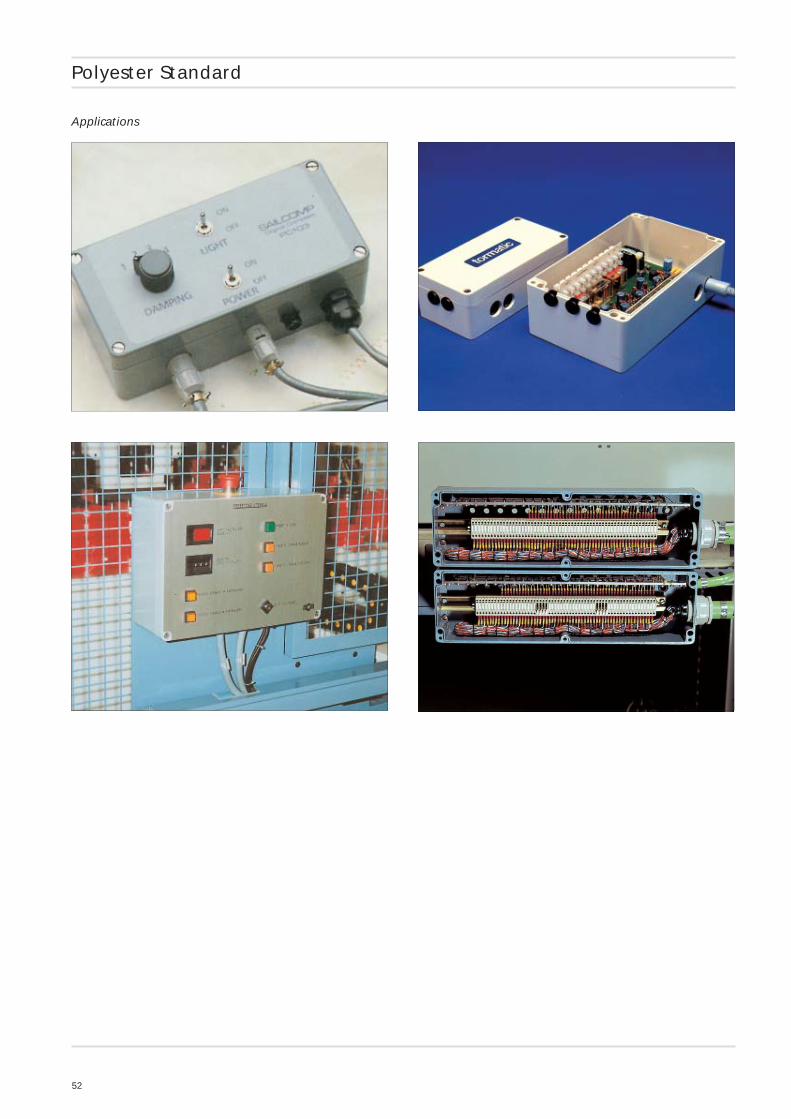
Polyester Standard
• Robust plastic enclosure for MCR and automation engineering• Fixing options for DIN rails and mounting plates• Universal configuration
Included in deliveryPlastic enclosure in glass fibre reinforcedpolyester, consisting of lid, seal, incl.captive +/- stainless steel screws, base with2 or 4 earthing screws
Technical data
Material:
glass fibre reinforced duroplastic polyester
Colour:
RAL 7000, squirrel grey
special colour on request
Ingress protection:
IP 66 to EN 60529
Impact resistance:
7 Joule to EN 60079-0
Surface resistance:
>1012 Ohm to IEC 60093
Flammability:
V0 / self-extinguishing, UL 94
Insulation:
fully insulated to VDE 0100
Disruptive strength:
18 KV/mm, IEC 60243-1
Toxicity:
halogen-free
Temperature range:
PU (polyurethane) seal (std.): -40°C to +90°C
CR (chloroprene) seal: -40°C to +100°C
VMQ (silicone) seal (optional): -60°C to +130°C
54
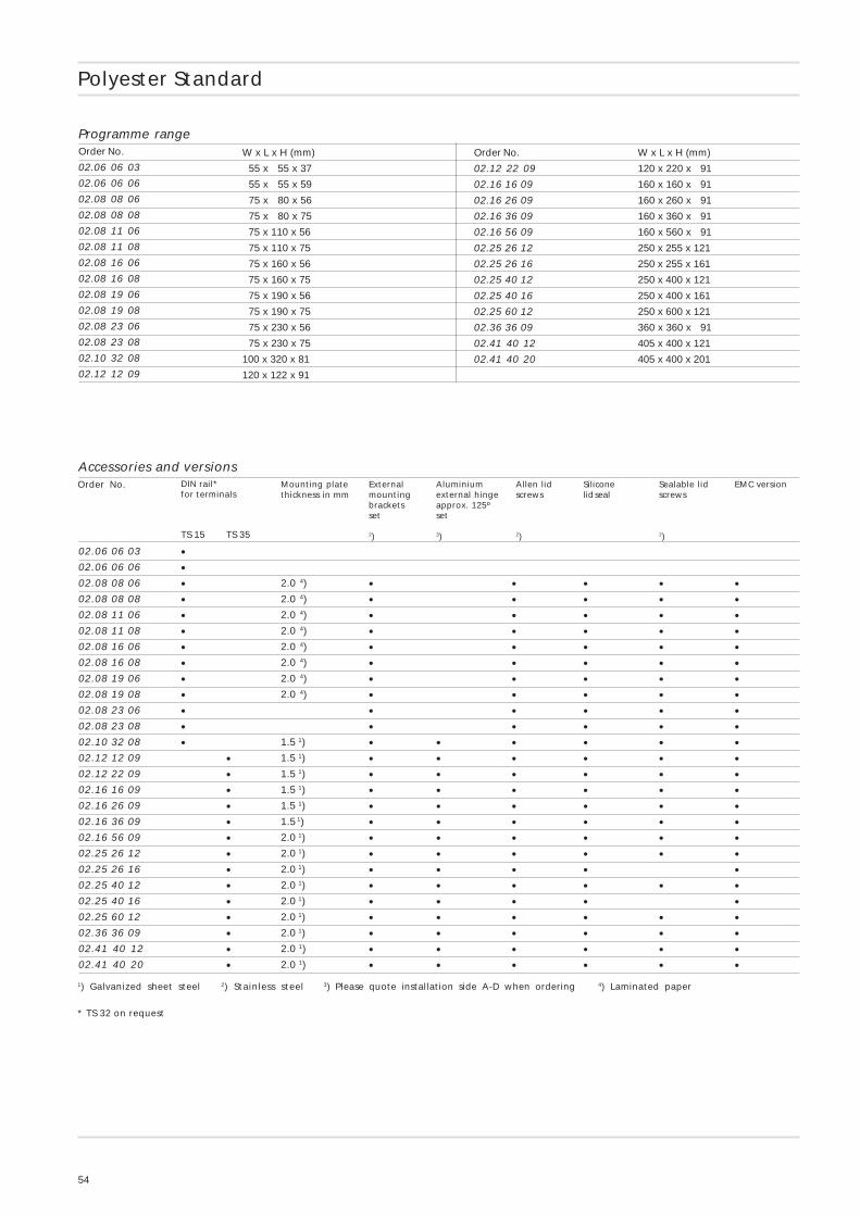
Programme rangeOrder No.
02.06 06 03
02.06 06 06
02.08 08 06
02.08 08 08
02.08 11 06
02.08 11 08
02.08 16 06
02.08 16 08
02.08 19 06
02.08 19 08
02.08 23 06
02.08 23 08
02.10 32 08
02.12 12 09
Polyester Standard
W x L x H (mm)
55 x 55 x 37
55 x 55 x 59
75 x 80 x 56
75 x 80 x 75
75 x 110 x 56
75 x 110 x 75
75 x 160 x 56
75 x 160 x 75
75 x 190 x 56
75 x 190 x 75
75 x 230 x 56
75 x 230 x 75
100 x 320 x 81
120 x 122 x 91
Order No.
02.12 22 09
02.16 16 09
02.16 26 09
02.16 36 09
02.16 56 09
02.25 26 12
02.25 26 16
02.25 40 12
02.25 40 16
02.25 60 12
02.36 36 09
02.41 40 12
02.41 40 20
W x L x H (mm)
120 x 220 x 91
160 x 160 x 91
160 x 260 x 91
160 x 360 x 91
160 x 560 x 91
250 x 255 x 121
250 x 255 x 161
250 x 400 x 121
250 x 400 x 161
250 x 600 x 121
360 x 360 x 91
405 x 400 x 121
405 x 400 x 201
Accessories and versionsMounting platethickness in mm
Externalmountingbracketsset
2)
Aluminiumexternal hingeapprox. 125ºset
3)
Allen lidscrews
2)
Siliconelid seal
Sealable lidscrews
2)
EMC versionDIN rail*for terminals
Order No.
02.06 06 03
02.06 06 06
02.08 08 06
02.08 08 08
02.08 11 06
02.08 11 08
02.08 16 06
02.08 16 08
02.08 19 06
02.08 19 08
02.08 23 06
02.08 23 08
02.10 32 08
02.12 12 09
02.12 22 09
02.16 16 09
02.16 26 09
02.16 36 09
02.16 56 09
02.25 26 12
02.25 26 16
02.25 40 12
02.25 40 16
02.25 60 12
02.36 36 09
02.41 40 12
02.41 40 20
2.0 4)
2.0 4)
2.0 4)
2.0 4)
2.0 4)
2.0 4)
2.0 4)
2.0 4)
1.5 1)
1.5 1)
1.5 1)
1.5 1)
1.5 1)
1.5 1)
2.0 1)
2.0 1)
2.0 1)
2.0 1)
2.0 1)
2.0 1)
2.0 1)
2.0 1)
2.0 1)
•••••••••••••
••••••••••••••
•••••••••••••••
•••••••••••••••••••••••••
••••••••••••••••••
•
••••
•••••••••••••••••••••••••
•••••••••••••••••••••••••
•••••••••••••••••••••••••
1) Galvanized sheet steel 2) Stainless steel 3) Please quote installation side A-D when ordering 4) Laminated paper
* TS 32 on request
TS 35TS 15
55
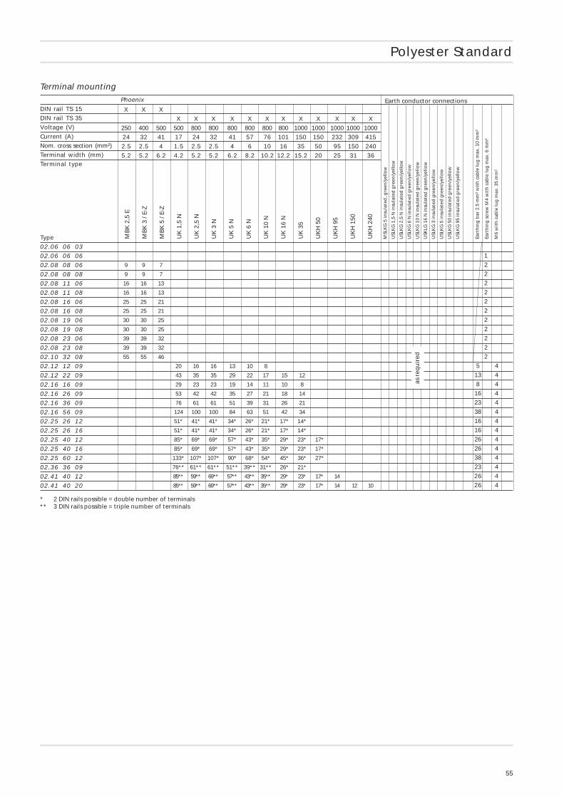
Polyester Standard
Phoenix
DIN rail TS 15
DIN rail TS 35
Voltage (V)
Current (A)
Nom. cross section (mm²)
Terminal width (mm)
Terminal type
Type
02.06 06 03
02.06 06 06
02.08 08 06
02.08 08 08
02.08 11 06
02.08 11 08
02.08 16 06
02.08 16 08
02.08 19 06
02.08 19 08
02.08 23 06
02.08 23 08
02.10 32 08
02.12 12 09
02.12 22 09
02.16 16 09
02.16 26 09
02.16 36 09
02.16 56 09
02.25 26 12
02.25 26 16
02.25 40 12
02.25 40 16
02.25 60 12
02.36 36 09
02.41 40 12
02.41 40 20
Terminal mounting
1
2
2
2
2
2
2
2
2
2
2
2
5 4
13 4
8 4
16 4
23 4
38 4
16 4
16 4
26 4
26 4
38 4
23 4
26 4
26 4
9 9 7
9 9 7
16 16 13
16 16 13
25 25 21
25 25 21
30 30 25
30 30 25
39 39 32
39 39 32
55 55 46
20 16 16 13 10 8
43 35 35 29 22 17 15 12
29 23 23 19 14 11 10 8
53 42 42 35 27 21 18 14
76 61 61 51 39 31 26 21
124 100 100 84 63 51 42 34
51* 41* 41* 34* 26* 21* 17* 14*
51* 41* 41* 34* 26* 21* 17* 14*
85* 69* 69* 57* 43* 35* 29* 23* 17*
85* 69* 69* 57* 43* 35* 29* 23* 17*
133* 107* 107* 90* 68* 54* 45* 36* 27*
76** 61** 61** 51** 39** 31** 26* 21*
85** 59** 69** 57** 43** 35** 29* 23* 17* 14
85** 59** 69** 57** 43** 35** 29* 23* 17* 14 12 10
MB
K 2
,5 E
MB
K 3
/ E-
Z
MB
K 5
/ E-
Z
UK
1,5
N
UK
2,5
N
UK
3 N
UK
5 N
UK
6 N
UK
10
N
UK
16
N
UK
35
UK
H 5
0
UK
H 9
5
UK
H 1
50
UK
H 2
40
X X X
X X X X X X X X X X X X
250 400 500 500 800 800 800 800 800 800 1000 1000 1000 1000 1000
24 32 41 17 24 32 41 57 76 101 150 150 232 309 415
2.5 2.5 4 1.5 2.5 2.5 4 6 10 16 35 50 95 150 240
5.2 5.2 6.2 4.2 5.2 5.2 6.2 8.2 10.2 12.2 15.2 20 25 31 36
Earth conductor connections
MSL
KG
5 in
sula
ted
, gre
en/y
ello
w
USL
KG
1,5
N in
sula
ted
gre
en/y
ello
w
USL
KG
2,5
N in
sula
ted
gre
en/y
ello
w
USL
KG
6 N
insu
late
d g
reen
/yel
low
USL
KG
10
N in
sula
ted
gre
en/y
ello
w
USK
LG 1
6 N
insu
late
d g
reen
/yel
low
USL
KG
3 in
sula
ted
gre
en/y
ello
w
USL
KG
5 in
sula
ted
gre
en/y
ello
w
USL
KG
50
insu
late
d g
reen
/yel
low
USL
KG
95
insu
late
d g
reen
/yel
low
Eart
hin
g b
ar 2
.5 m
m²
wit
h c
able
lug
max
. 10
mm
²
Eart
hin
g s
crew
M4
wit
h c
able
lug
max
. 6 m
m²
M6
wit
h c
able
lug
max
. 35
mm
²
as r
equ
ired
* 2 DIN rails possible = double number of terminals** 3 DIN rails possible = triple number of terminals
56
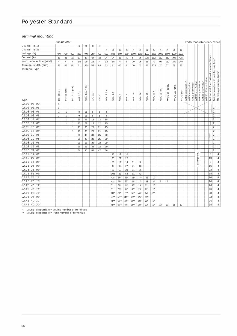
Polyester Standard
Weidmüller
DIN rail TS 15
DIN rail TS 35
Voltage (V)
Current (A)
Nom. cross section (mm²)
Terminal width (mm)
Terminal type
Type
02.06 06 03
02.06 06 06
02.08 08 06
02.08 08 08
02.08 11 06
02.08 11 08
02.08 16 06
02.08 16 08
02.08 19 06
02.08 19 08
02.08 23 06
02.08 23 08
02.10 32 08
02.12 12 09
02.12 22 09
02.16 16 09
02.16 26 09
02.16 36 09
02.16 56 09
02.25 26 12
02.25 26 16
02.25 40 12
02.25 40 16
02.25 60 12
02.36 36 09
02.41 40 12
02.41 40 20
Terminal mounting
1
2
2
2
2
2
2
2
2
2
2
2
5 4
13 4
8 4
16 4
23 4
38 4
16 4
16 4
26 4
26 4
38 4
23 4
26 4
26 4
1
1
1 1 8 11 8 6 8
1 1 9 11 8 6 8
1 1 15 21 15 12 15
1 1 15 21 15 12 15
1 25 36 25 21 25
1 25 36 25 21 25
30 43 30 25 30
30 43 30 25 30
39 56 39 32 39
39 56 39 32 39
56 80 56 47 56
16 13 10
35 29 22
23 19 14 11 9
43 36 27 21 18
63 52 39 31 26
103 86 64 51 43
42* 35* 26* 21* 17* 13 10
42* 35* 26* 21* 17* 13 10 7 7
71* 59* 44* 35* 29* 22* 17
71* 59* 44* 35* 29* 22* 17
111* 92* 69* 55* 46* 34* 27
63** 52** 39** 31** 26* 19*
71** 59** 44** 35** 29* 22* 17
71** 59** 44** 35** 29* 22* 17 13 13 11 10
BK
4 (
4 p
ole
)
BK
6 (
6 p
ole
)
BK
12
(12
po
le)
AK
Z 1
,5
WD
U 1
,5 /
R 3
,5
AK
Z 2
,5
AK
Z 4
WD
U 2
,5 N
WD
U 2
,5
WD
U 4
WD
U 6
WD
U 1
0
WD
U 1
6
WD
U 3
5
WD
U 7
0 N
WD
U 7
0 /
95
WD
U 9
5 / 1
20 N
WD
U 1
20 /
150
WD
U 2
40
X X X X
X X X X X X X X X X X X
400 400 400 250 400 250 400 500 800 800 800 1000 1000 1000 1000 1000 1000 1000 1000
32 32 32 17 17 24 32 24 24 32 41 57 76 125 192 232 269 309 415
4 4 4 1.5 1.5 2.5 4 2.5 2.5 4 6 10 16 35 70 95 120 150 240
38 52 92 5.1 3.5 5.1 6.1 5.1 5.1 6.1 8 10 12 16 20.5 27 27 32 36
Earth conductor connections
WPE
2,5
gre
en/y
ello
w
WPE
4 g
reen
/yel
low
WPE
6 g
reen
/yel
low
WPE
10
gre
en/y
ello
w
WPE
16
gre
en/y
ello
w
WPE
35
gre
en/y
ello
w
WPE
70
/ 95
gre
en/y
ello
w
Eart
hin
g b
ar 2
.5 m
m²
wit
h c
able
lug
max
. 10
mm
²
Eart
hin
g s
crew
M4
wit
h c
able
lug
max
. 6 m
m²
M6
wit
h c
able
lug
max
. 35
mm
²
as r
equ
ired
* 2 DIN rails possible = double number of terminals** 3 DIN rails possible = triple number of terminals
57
Polyester Standard
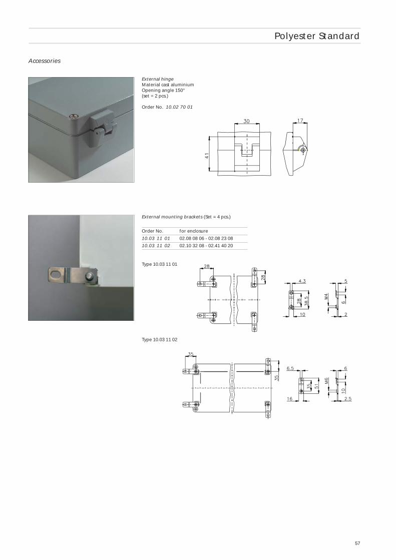
Accessories
External hingeMaterial cast aluminiumOpening angle 150°(set = 2 pcs.)
Order No. 10.02 70 01
External mounting brackets (Set = 4 pcs.)
Order No. for enclosure
10.03 11 01 02.08 08 06 - 02.08 23 08
10.03 11 02 02.10 32 08 - 02.41 40 20
Type 10.03 11 01
Type 10.03 11 02
58
DIN
rai
lle
ng
th in
mm
Mo
un
tin
g p
late
(th
ickn
ess
in m
m)
Exte
rnal
mo
un
tin
gb
rack
ets
Exte
rnal
hin
ge*
set
EMC
ver
sio
n
Alle
n li
d s
crew
s
Silic
on
e lid
seal
C DA
B
CD
M AB
PG
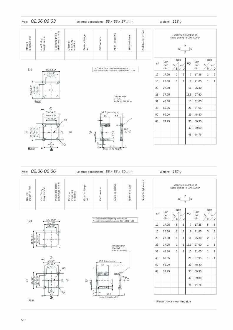
12 17.25 2 2 7 17.25 2 2
16 25.30 1 1 9 21.85 1 1
20 27.60 11 25.30
25 37.95 13.5 27.60
32 48.30 16 31.05
40 60.95 21 37.95
50 69.00 29 48.30
63 74.75 36 60.95
42 69.00
48 74.75
CD
AB
Maximum number ofcable glands to DIN 50262*
Cor-nerdim.
Cor-nerdim.
SideSide
Seal
able
lid
scr
ews
Type: 02.06 06 03 External dimensions: 55 x 55 x 37 mm Weight: 118 g
max
. fit
tin
gle
ng
th in
mm
C DA
B
CD
M AB
PG
12 17.25 5 5 7 17.25 5 5
16 25.30 2 2 9 21.85 3 3
20 27.60 1 1 11 25.30 2 2
25 37.95 1 1 13.5 27.60 1 1
32 48.30 1 1 16 31.05 1 1
40 60.95 21 37.95 1 1
50 69.00 29 48.30
63 74.75 36 60.95
42 69.00
48 74.75
CD
AB
Maximum number ofcable glands to DIN 50262*
Cor-nerdim.
Cor-nerdim.
SideSide
Type: 02.06 06 06 External dimensions: 55 x 55 x 59 mm Weight: 152 g
DIN
rai
lle
ng
th in
mm
Mo
un
tin
g p
late
(th
ickn
ess
in m
m)
Exte
rnal
mo
un
tin
gb
rack
ets
Exte
rnal
hin
ge*
set
EMC
ver
sio
n
Alle
n li
d s
crew
s
Silic
on
e lid
seal
Seal
able
lid
scr
ews
max
. fit
tin
gle
ng
th in
mm
Lid * = Conical form tapering downwardsFree dimensions-tolerance to DIN 16901 - 130
Cylinder screwM4x18/7similar to DIN 84
(total height)
(max. fitting height)Base
Lid* = Conical form tapering downwardsFree dimensions-tolerance to DIN 16901 - 130
Cylinder screwM4x18/7similar to DIN 84
(total height)
(max. fitting height)
Base
Top
Top
* Please quote mounting side
59
C DA
B
CD
M AB
PG
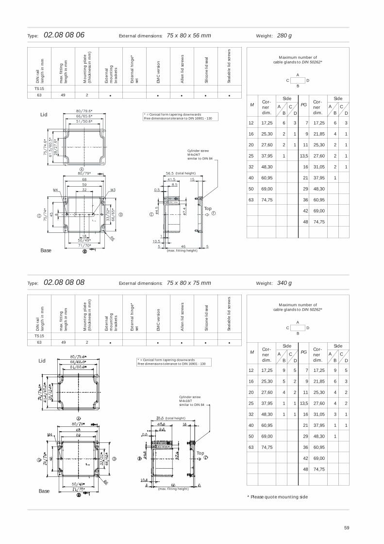
12 17,25 6 3 7 17,25 6 3
16 25,30 2 1 9 21,85 4 1
20 27,60 2 1 11 25,30 2 1
25 37,95 1 13,5 27,60 2 1
32 48,30 16 31,05 2 1
40 60,95 21 37,95 1
50 69,00 29 48,30
63 74,75 36 60,95
42 69,00
48 74,75
CD
AB
Maximum number ofcable glands to DIN 50262*
Cor-nerdim.
Cor-nerdim.
SideSide
Type: 02.08 08 06 External dimensions: 75 x 80 x 56 mm Weight: 280 g
C DA
B
CD
M AB
PG
12 17,25 9 5 7 17,25 9 5
16 25,30 5 2 9 21,85 6 3
20 27,60 4 2 11 25,30 4 2
25 37,95 1 1 13,5 27,60 4 2
32 48,30 1 1 16 31,05 3 1
40 60,95 21 37,95 1 1
50 69,00 29 48,30 1
63 74,75 36 60,95
42 69,00
48 74,75
CD
AB
Maximum number ofcable glands to DIN 50262*
Cor-nerdim.
Cor-nerdim.
SideSide
Type: 02.08 08 08 External dimensions: 75 x 80 x 75 mm Weight: 340 g
• • ••63
TS 15
•2
• • ••63
TS 15
•249
49
DIN
rai
lle
ng
th in
mm
Mo
un
tin
g p
late
(th
ickn
ess
in m
m)
Exte
rnal
mo
un
tin
gb
rack
ets
Exte
rnal
hin
ge*
set
EMC
ver
sio
n
Alle
n li
d s
crew
s
Silic
on
e lid
seal
Seal
able
lid
scr
ews
max
. fit
tin
gle
ng
th in
mm
DIN
rai
lle
ng
th in
mm
Mo
un
tin
g p
late
(th
ickn
ess
in m
m)
Exte
rnal
mo
un
tin
gb
rack
ets
Exte
rnal
hin
ge*
set
EMC
ver
sio
n
Alle
n li
d s
crew
s
Silic
on
e lid
seal
Seal
able
lid
scr
ews
max
. fit
tin
gle
ng
th in
mm
Lid * = Conical form tapering downwardsFree dimensions-tolerance to DIN 16901 - 130
Cylinder screwM4x24/7similar to DIN 84
(total height)
(max. fitting height)Base
Top
Lid * = Conical form tapering downwardsFree dimensions-tolerance to DIN 16901 - 130
Cylinder screwM4x18/7similar to DIN 84
(total height)
(max. fitting height)Base
Top
* Please quote mounting side
60
C DA
B
CD
M AB
PG
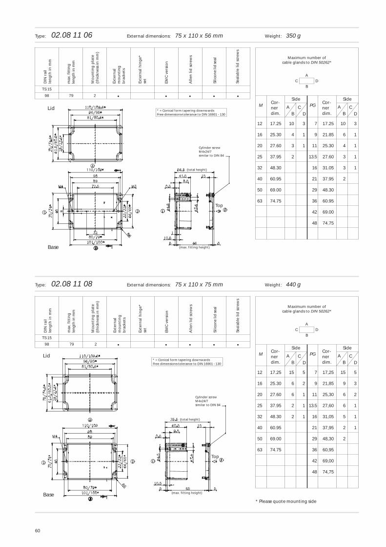
12 17.25 10 3 7 17.25 10 3
16 25.30 4 1 9 21.85 6 1
20 27.60 3 1 11 25.30 4 1
25 37.95 2 13.5 27.60 3 1
32 48.30 16 31.05 3 1
40 60.95 21 37.95 2
50 69.00 29 48.30
63 74.75 36 60.95
42 69.00
48 74.75
CD
AB
Maximum number ofcable glands to DIN 50262*
Cor-nerdim.
Cor-nerdim.
SideSide
Type: 02.08 11 06 External dimensions: 75 x 110 x 56 mm Weight: 350 g
C DA
B
CD
M AB
PG
12 17.25 15 5 7 17,25 15 5
16 25.30 6 2 9 21,85 9 3
20 27.60 6 1 11 25,30 6 2
25 37.95 2 1 13.5 27,60 6 1
32 48.30 2 1 16 31,05 5 1
40 60.95 21 37,95 2 1
50 69.00 29 48,30 2
63 74.75 36 60,95
42 69,00
48 74,75
CD
AB
Maximum number ofcable glands to DIN 50262*
Cor-nerdim.
Cor-nerdim.
SideSide
Type: 02.08 11 08 External dimensions: 75 x 110 x 75 mm Weight: 440 g
• • ••98
TS 15
•2
• • ••98
TS 15
•
79
79 2
DIN
rai
lle
ng
th in
mm
Mo
un
tin
g p
late
(th
ickn
ess
in m
m)
Exte
rnal
mo
un
tin
gb
rack
ets
Exte
rnal
hin
ge*
set
EMC
ver
sio
n
Alle
n li
d s
crew
s
Silic
on
e lid
seal
Seal
able
lid
scr
ews
max
. fit
tin
gle
ng
th in
mm
DIN
rai
lle
ng
th in
mm
Mo
un
tin
g p
late
(th
ickn
ess
in m
m)
Exte
rnal
mo
un
tin
gb
rack
ets
Exte
rnal
hin
ge*
set
EMC
ver
sio
n
Alle
n li
d s
crew
s
Silic
on
e lid
seal
Seal
able
lid
scr
ews
max
. fit
tin
gle
ng
th in
mm
Base
Lid * = Conical form tapering downwardsFree dimensions-tolerance to DIN 16901 - 130
Cylinder screwM4x24/7similar to DIN 84
(total height)
(max. fitting height)
Top
Base
Lid* = Conical form tapering downwardsFree dimensions-tolerance to DIN 16901 - 130
Cylinder screwM4x24/7similar to DIN 84
(total height)
(max. fitting height)
Top
* Please quote mounting side
61
C DA
B
CD
M AB
PG
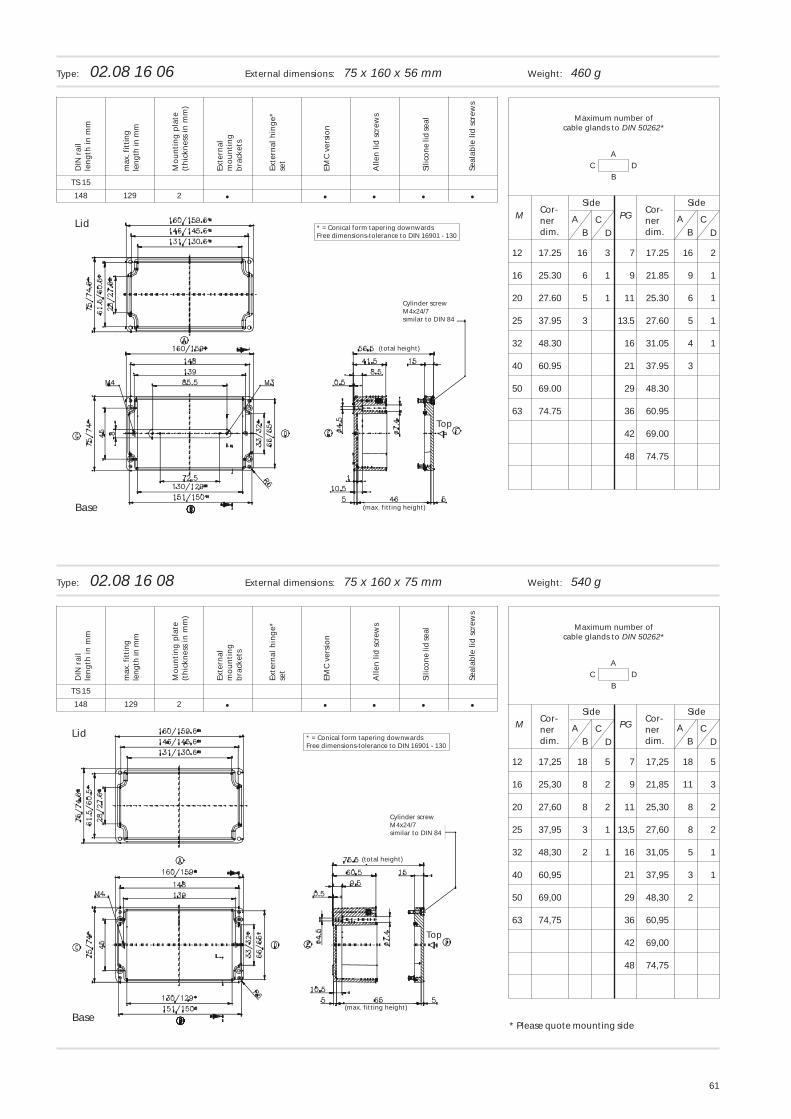
12 17.25 16 3 7 17.25 16 2
16 25.30 6 1 9 21.85 9 1
20 27.60 5 1 11 25.30 6 1
25 37.95 3 13.5 27.60 5 1
32 48.30 16 31.05 4 1
40 60.95 21 37.95 3
50 69.00 29 48.30
63 74.75 36 60.95
42 69.00
48 74.75
CD
AB
Maximum number ofcable glands to DIN 50262*
Cor-nerdim.
Cor-nerdim.
SideSide
Type: 02.08 16 06 External dimensions: 75 x 160 x 56 mm Weight: 460 g
C DA
B
CD
M AB
PG
12 17,25 18 5 7 17,25 18 5
16 25,30 8 2 9 21,85 11 3
20 27,60 8 2 11 25,30 8 2
25 37,95 3 1 13,5 27,60 8 2
32 48,30 2 1 16 31,05 5 1
40 60,95 21 37,95 3 1
50 69,00 29 48,30 2
63 74,75 36 60,95
42 69,00
48 74,75
CD
AB
Maximum number ofcable glands to DIN 50262*
Cor-nerdim.
Cor-nerdim.
SideSide
Type: 02.08 16 08 External dimensions: 75 x 160 x 75 mm Weight: 540 g
• • ••148
TS 15
•2
• • ••148
TS 15
•129
129
2
DIN
rai
lle
ng
th in
mm
Mo
un
tin
g p
late
(th
ickn
ess
in m
m)
Exte
rnal
mo
un
tin
gb
rack
ets
Exte
rnal
hin
ge*
set
EMC
ver
sio
n
Alle
n li
d s
crew
s
Silic
on
e lid
seal
Seal
able
lid
scr
ews
max
. fit
tin
gle
ng
th in
mm
DIN
rai
lle
ng
th in
mm
Mo
un
tin
g p
late
(th
ickn
ess
in m
m)
Exte
rnal
mo
un
tin
gb
rack
ets
Exte
rnal
hin
ge*
set
EMC
ver
sio
n
Alle
n li
d s
crew
s
Silic
on
e lid
seal
Seal
able
lid
scr
ews
max
. fit
tin
gle
ng
th in
mm
Base
Lid * = Conical form tapering downwardsFree dimensions-tolerance to DIN 16901 - 130
Cylinder screwM4x24/7similar to DIN 84
(total height)
(max. fitting height)
Top
Base
Lid * = Conical form tapering downwardsFree dimensions-tolerance to DIN 16901 - 130
Cylinder screwM4x24/7similar to DIN 84
(total height)
(max. fitting height)
Top
* Please quote mounting side
62
C DA
B
CD
M AB
PG
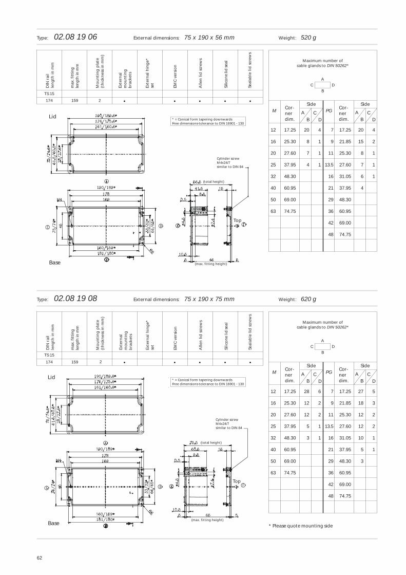
12 17.25 20 4 7 17.25 20 4
16 25.30 8 1 9 21.85 15 2
20 27.60 7 1 11 25.30 8 1
25 37.95 4 1 13.5 27.60 7 1
32 48.30 16 31.05 6 1
40 60.95 21 37.95 4
50 69.00 29 48.30
63 74.75 36 60.95
42 69.00
48 74.75
CD
AB
Maximum number ofcable glands to DIN 50262*
Cor-nerdim.
Cor-nerdim.
SideSide
Type: 02.08 19 06 External dimensions: 75 x 190 x 56 mm Weight: 520 g
C DA
B
CD
M AB
PG
12 17.25 28 6 7 17.25 27 5
16 25.30 12 2 9 21.85 18 3
20 27.60 12 2 11 25.30 12 2
25 37.95 5 1 13.5 27.60 12 2
32 48.30 3 1 16 31.05 10 1
40 60.95 21 37.95 5 1
50 69.00 29 48.30 3
63 74.75 36 60.95
42 69.00
48 74.75
CD
AB
Maximum number ofcable glands to DIN 50262*
Cor-nerdim.
Cor-nerdim.
SideSide
Type: 02.08 19 08 External dimensions: 75 x 190 x 75 mm Weight: 620 g
• • ••174
TS 15
•2
• • ••174
TS 15
•
159
159 2
DIN
rai
lle
ng
th in
mm
Mo
un
tin
g p
late
(th
ickn
ess
in m
m)
Exte
rnal
mo
un
tin
gb
rack
ets
Exte
rnal
hin
ge*
set
EMC
ver
sio
n
Alle
n li
d s
crew
s
Silic
on
e lid
seal
Seal
able
lid
scr
ews
max
. fit
tin
gle
ng
th in
mm
DIN
rai
lle
ng
th in
mm
Mo
un
tin
g p
late
(th
ickn
ess
in m
m)
Exte
rnal
mo
un
tin
gb
rack
ets
Exte
rnal
hin
ge*
set
EMC
ver
sio
n
Alle
n li
d s
crew
s
Silic
on
e lid
seal
Seal
able
lid
scr
ews
max
. fit
tin
gle
ng
th in
mm
Base
Lid* = Conical form tapering downwardsFree dimensions-tolerance to DIN 16901 - 130
Cylinder screwM4x24/7similar to DIN 84
(total height)
(max. fitting height)
Top
Base
Lid* = Conical form tapering downwardsFree dimensions-tolerance to DIN 16901 - 130
Cylinder screwM4x24/7similar to DIN 84
(total height)
(max. fitting height)
Top
* Please quote mounting side
63
C DA
B
CD
M AB
PG
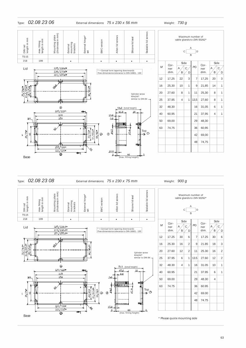
12 17,25 22 3 7 17,25 20 3
16 25,30 10 1 9 21,85 14 1
20 27,60 8 1 11 25,30 8 1
25 37,95 4 1 13,5 27,60 8 1
32 48,30 16 31,05 6 1
40 60,95 21 37,95 4 1
50 69,00 29 48,30
63 74,75 36 60,95
42 69,00
48 74,75
CD
AB
Maximum number ofcable glands to DIN 50262*
Cor-nerdim.
Cor-nerdim.
SideSide
Type: 02.08 23 06 External dimensions: 75 x 230 x 56 mm Weight: 730 g
C DA
B
CD
M AB
PG
12 17.25 30 6 7 17.25 30 6
16 25.30 16 2 9 21.85 18 3
20 27.60 12 2 11 25.30 16 2
25 37.95 6 1 13.5 27.60 12 2
32 48.30 4 1 16 31.05 10 1
40 60.95 21 37.95 6 1
50 69.00 29 48.30 4
63 74.75 36 60.95
42 69.00
48 74.75
CD
AB
Maximum number ofcable glands to DIN 50262*
Cor-nerdim.
Cor-nerdim.
SideSide
Type: 02.08 23 08 External dimensions: 75 x 230 x 75 mm Weight: 900 g
• • ••218
TS 15
•
• • ••218
TS 15
•
199
199
DIN
rai
lle
ng
th in
mm
Mo
un
tin
g p
late
(th
ickn
ess
in m
m)
Exte
rnal
mo
un
tin
gb
rack
ets
Exte
rnal
hin
ge*
set
EMC
ver
sio
n
Alle
n li
d s
crew
s
Silic
on
e lid
seal
Seal
able
lid
scr
ews
max
. fit
tin
gle
ng
th in
mm
DIN
rai
lle
ng
th in
mm
Mo
un
tin
g p
late
(th
ickn
ess
in m
m)
Exte
rnal
mo
un
tin
gb
rack
ets
Exte
rnal
hin
ge*
set
EMC
ver
sio
n
Alle
n li
d s
crew
s
Silic
on
e lid
seal
Seal
able
lid
scr
ews
max
. fit
tin
gle
ng
th in
mm
Base
Lid* = Conical form tapering downwardsFree dimensions-tolerance to DIN 16901 - 130
Cylinder screwM4x24/7similar to DIN 84
(total height)
(max. fitting height)
Top
Base
Lid * = Conical form tapering downwardsFree dimensions-tolerance to DIN 16901 - 130
Cylinder screwM4x24/7similar to DIN 84
(total height)
(max. fitting height)
Top
* Please quote mounting side
64
C DA
B
CD
M AB
PG
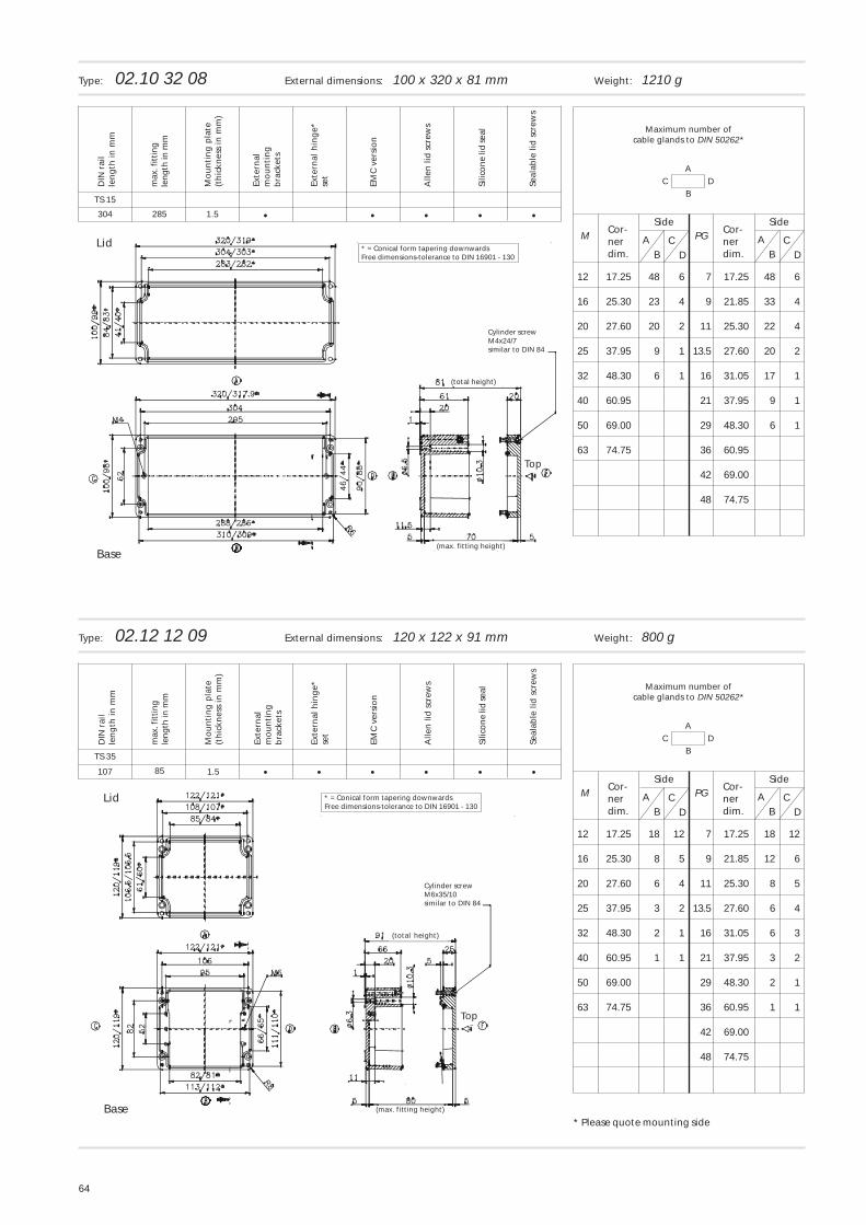
12 17.25 48 6 7 17.25 48 6
16 25.30 23 4 9 21.85 33 4
20 27.60 20 2 11 25.30 22 4
25 37.95 9 1 13.5 27.60 20 2
32 48.30 6 1 16 31.05 17 1
40 60.95 21 37.95 9 1
50 69.00 29 48.30 6 1
63 74.75 36 60.95
42 69.00
48 74.75
CD
AB
Maximum number ofcable glands to DIN 50262*
Cor-nerdim.
Cor-nerdim.
SideSide
Type: 02.10 32 08 External dimensions: 100 x 320 x 81 mm Weight: 1210 g
C DA
B
CD
M AB
PG
12 17.25 18 12 7 17.25 18 12
16 25.30 8 5 9 21.85 12 6
20 27.60 6 4 11 25.30 8 5
25 37.95 3 2 13.5 27.60 6 4
32 48.30 2 1 16 31.05 6 3
40 60.95 1 1 21 37.95 3 2
50 69.00 29 48.30 2 1
63 74.75 36 60.95 1 1
42 69.00
48 74.75
CD
AB
Maximum number ofcable glands to DIN 50262*
Cor-nerdim.
Cor-nerdim.
SideSide
Type: 02.12 12 09 External dimensions: 120 x 122 x 91 mm Weight: 800 g
• • ••304
TS 15
•1.5
• • ••107
TS 35
•1.5 •
285
85
DIN
rai
lle
ng
th in
mm
Mo
un
tin
g p
late
(th
ickn
ess
in m
m)
Exte
rnal
mo
un
tin
gb
rack
ets
Exte
rnal
hin
ge*
set
EMC
ver
sio
n
Alle
n li
d s
crew
s
Silic
on
e lid
seal
Seal
able
lid
scr
ews
max
. fit
tin
gle
ng
th in
mm
DIN
rai
lle
ng
th in
mm
Mo
un
tin
g p
late
(th
ickn
ess
in m
m)
Exte
rnal
mo
un
tin
gb
rack
ets
Exte
rnal
hin
ge*
set
EMC
ver
sio
n
Alle
n li
d s
crew
s
Silic
on
e lid
seal
Seal
able
lid
scr
ews
max
. fit
tin
gle
ng
th in
mm
Base
Lid * = Conical form tapering downwardsFree dimensions-tolerance to DIN 16901 - 130
Cylinder screwM4x24/7similar to DIN 84
(total height)
(max. fitting height)
Top
Base
Lid * = Conical form tapering downwardsFree dimensions-tolerance to DIN 16901 - 130
Cylinder screwM6x35/10similar to DIN 84
(total height)
(max. fitting height)
Top
* Please quote mounting side
65
C DA
B
CD
M AB
PG
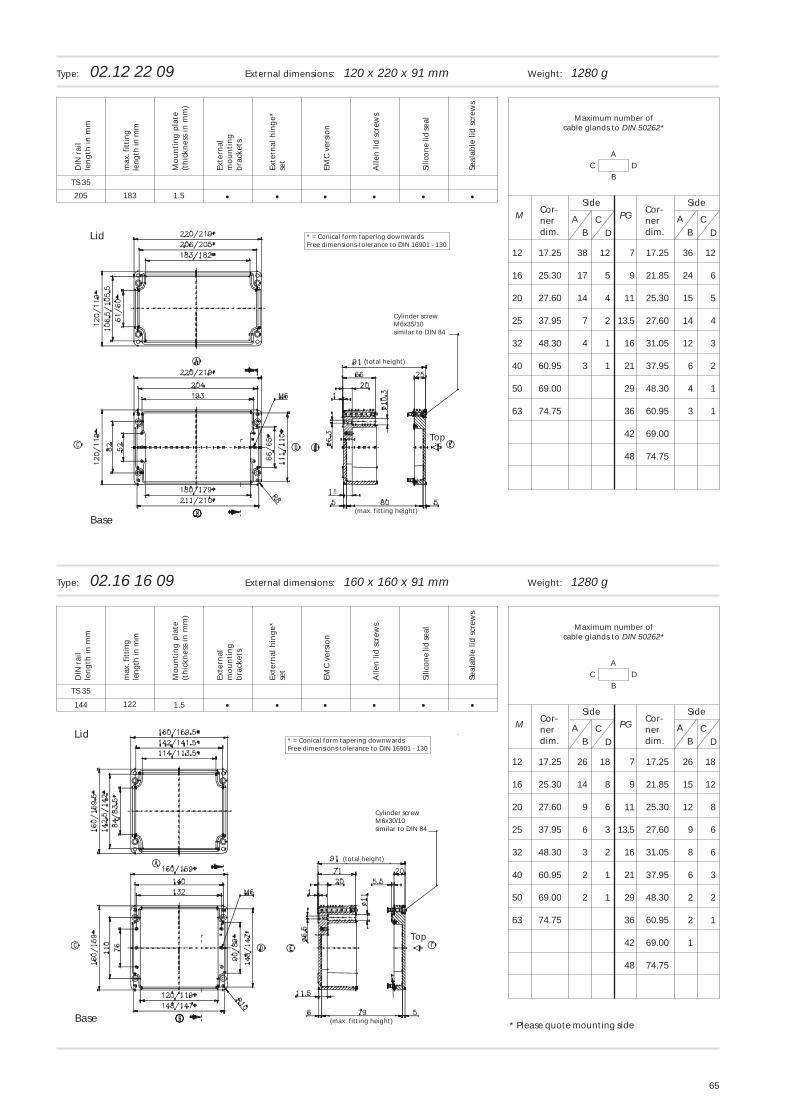
12 17.25 38 12 7 17.25 36 12
16 25.30 17 5 9 21.85 24 6
20 27.60 14 4 11 25.30 15 5
25 37.95 7 2 13.5 27.60 14 4
32 48.30 4 1 16 31.05 12 3
40 60.95 3 1 21 37.95 6 2
50 69.00 29 48.30 4 1
63 74.75 36 60.95 3 1
42 69.00
48 74.75
CD
AB
Maximum number ofcable glands to DIN 50262*
Cor-nerdim.
Cor-nerdim.
SideSide
Type: 02.12 22 09 External dimensions: 120 x 220 x 91 mm Weight: 1280 g
C DA
B
CD
M AB
PG
12 17.25 26 18 7 17.25 26 18
16 25.30 14 8 9 21.85 15 12
20 27.60 9 6 11 25.30 12 8
25 37.95 6 3 13.5 27.60 9 6
32 48.30 3 2 16 31.05 8 6
40 60.95 2 1 21 37.95 6 3
50 69.00 2 1 29 48.30 2 2
63 74.75 36 60.95 2 1
42 69.00 1
48 74.75
CD
AB
Maximum number ofcable glands to DIN 50262*
Cor-nerdim.
Cor-nerdim.
SideSide
Type: 02.16 16 09 External dimensions: 160 x 160 x 91 mm Weight: 1280 g
• • ••205
TS 35
•
• • ••144
TS 35
•
1.5 •
1.5 •122
183
DIN
rai
lle
ng
th in
mm
Mo
un
tin
g p
late
(th
ickn
ess
in m
m)
Exte
rnal
mo
un
tin
gb
rack
ets
Exte
rnal
hin
ge*
set
EMC
ver
sio
n
Alle
n li
d s
crew
s
Silic
on
e lid
seal
Seal
able
lid
scr
ews
max
. fit
tin
gle
ng
th in
mm
DIN
rai
lle
ng
th in
mm
Mo
un
tin
g p
late
(th
ickn
ess
in m
m)
Exte
rnal
mo
un
tin
gb
rack
ets
Exte
rnal
hin
ge*
set
EMC
ver
sio
n
Alle
n li
d s
crew
s
Silic
on
e lid
seal
Seal
able
lid
scr
ews
max
. fit
tin
gle
ng
th in
mm
Base
Lid * = Conical form tapering downwardsFree dimensions-tolerance to DIN 16901 - 130
Cylinder screwM6x35/10similar to DIN 84
(total height)
(max. fitting height)
Top
Base
Lid* = Conical form tapering downwardsFree dimensions-tolerance to DIN 16901 - 130
Cylinder screwM6x30/10similar to DIN 84
(total height)
(max. fitting height)
Top
* Please quote mounting side
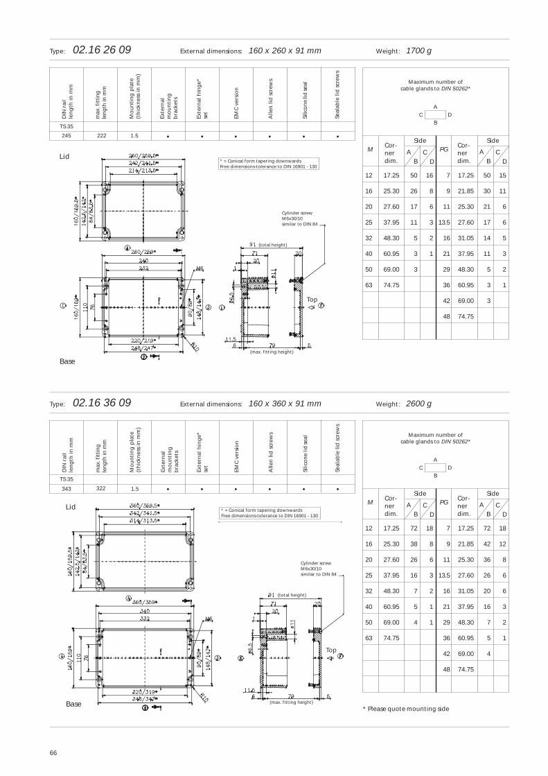
66
C DA
B
CD
M AB
PG
12 17.25 50 16 7 17.25 50 15
16 25.30 26 8 9 21.85 30 11
20 27.60 17 6 11 25.30 21 6
25 37.95 11 3 13.5 27.60 17 6
32 48.30 5 2 16 31.05 14 5
40 60.95 3 1 21 37.95 11 3
50 69.00 3 29 48.30 5 2
63 74.75 36 60.95 3 1
42 69.00 3
48 74.75
CD
AB
Maximum number ofcable glands to DIN 50262*
Cor-nerdim.
Cor-nerdim.
SideSide
Type: 02.16 26 09 External dimensions: 160 x 260 x 91 mm Weight: 1700 g
C DA
B
CD
M AB
PG
12 17.25 72 18 7 17.25 72 18
16 25.30 38 8 9 21.85 42 12
20 27.60 26 6 11 25.30 36 8
25 37.95 16 3 13.5 27.60 26 6
32 48.30 7 2 16 31.05 20 6
40 60.95 5 1 21 37.95 16 3
50 69.00 4 1 29 48.30 7 2
63 74.75 36 60.95 5 1
42 69.00 4
48 74.75
CD
AB
Maximum number ofcable glands to DIN 50262*
Cor-nerdim.
Cor-nerdim.
SideSide
Type: 02.16 36 09 External dimensions: 160 x 360 x 91 mm Weight: 2600 g
• • ••245
TS 35
•1.5
• • ••343
TS 35
•1.5 •
•222
322
DIN
rai
lle
ng
th in
mm
Mo
un
tin
g p
late
(th
ickn
ess
in m
m)
Exte
rnal
mo
un
tin
gb
rack
ets
Exte
rnal
hin
ge*
set
EMC
ver
sio
n
Alle
n li
d s
crew
s
Silic
on
e lid
seal
Seal
able
lid
scr
ews
max
. fit
tin
gle
ng
th in
mm
DIN
rai
lle
ng
th in
mm
Mo
un
tin
g p
late
(th
ickn
ess
in m
m)
Exte
rnal
mo
un
tin
gb
rack
ets
Exte
rnal
hin
ge*
set
EMC
ver
sio
n
Alle
n li
d s
crew
s
Silic
on
e lid
seal
Seal
able
lid
scr
ews
max
. fit
tin
gle
ng
th in
mm
Base
Lid* = Conical form tapering downwardsFree dimensions-tolerance to DIN 16901 - 130
Cylinder screwM6x30/10similar to DIN 84
(total height)
(max. fitting height)
Top
Base
Lid * = Conical form tapering downwardsFree dimensions-tolerance to DIN 16901 - 130
Cylinder screwM6x30/10similar to DIN 84
(total height)
(max. fitting height)
Top
* Please quote mounting side
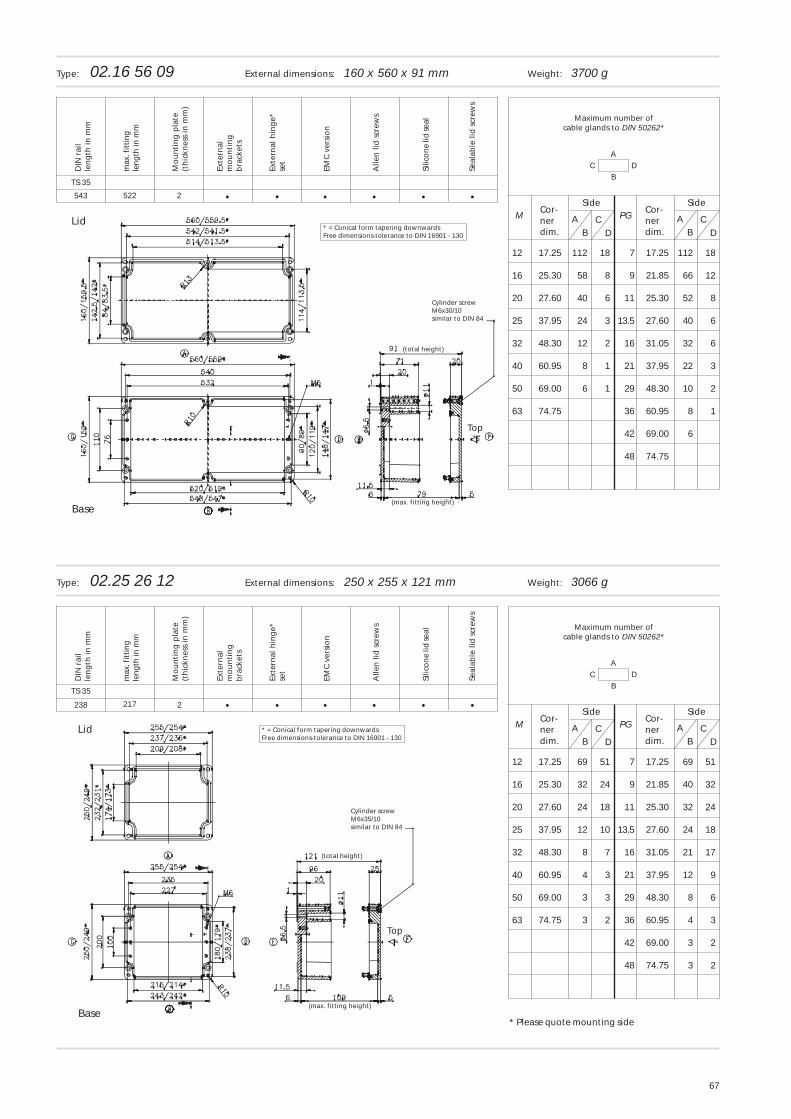
67
C DA
B
CD
M AB
PG
12 17.25 112 18 7 17.25 112 18
16 25.30 58 8 9 21.85 66 12
20 27.60 40 6 11 25.30 52 8
25 37.95 24 3 13.5 27.60 40 6
32 48.30 12 2 16 31.05 32 6
40 60.95 8 1 21 37.95 22 3
50 69.00 6 1 29 48.30 10 2
63 74.75 36 60.95 8 1
42 69.00 6
48 74.75
CD
AB
Maximum number ofcable glands to DIN 50262*
Cor-nerdim.
Cor-nerdim.
SideSide
Type: 02.16 56 09 External dimensions: 160 x 560 x 91 mm Weight: 3700 g
C DA
B
CD
M AB
PG
12 17.25 69 51 7 17.25 69 51
16 25.30 32 24 9 21.85 40 32
20 27.60 24 18 11 25.30 32 24
25 37.95 12 10 13.5 27.60 24 18
32 48.30 8 7 16 31.05 21 17
40 60.95 4 3 21 37.95 12 9
50 69.00 3 3 29 48.30 8 6
63 74.75 3 2 36 60.95 4 3
42 69.00 3 2
48 74.75 3 2
CD
AB
Maximum number ofcable glands to DIN 50262*
Cor-nerdim.
Cor-nerdim.
SideSide
Type: 02.25 26 12 External dimensions: 250 x 255 x 121 mm Weight: 3066 g
• • ••543
TS 35
•
• • ••238
TS 35
•
2 •
2 •
522
217
DIN
rai
lle
ng
th in
mm
Mo
un
tin
g p
late
(th
ickn
ess
in m
m)
Exte
rnal
mo
un
tin
gb
rack
ets
Exte
rnal
hin
ge*
set
EMC
ver
sio
n
Alle
n li
d s
crew
s
Silic
on
e lid
seal
Seal
able
lid
scr
ews
max
. fit
tin
gle
ng
th in
mm
DIN
rai
lle
ng
th in
mm
Mo
un
tin
g p
late
(th
ickn
ess
in m
m)
Exte
rnal
mo
un
tin
gb
rack
ets
Exte
rnal
hin
ge*
set
EMC
ver
sio
n
Alle
n li
d s
crew
s
Silic
on
e lid
seal
Seal
able
lid
scr
ews
max
. fit
tin
gle
ng
th in
mm
Base
Lid * = Conical form tapering downwardsFree dimensions-tolerance to DIN 16901 - 130
Cylinder screwM6x35/10similar to DIN 84
(total height)
(max. fitting height)
Top
Base
Lid* = Conical form tapering downwardsFree dimensions-tolerance to DIN 16901 - 130
Cylinder screwM6x30/10similar to DIN 84
(total height)
(max. fitting height)
Top
* Please quote mounting side
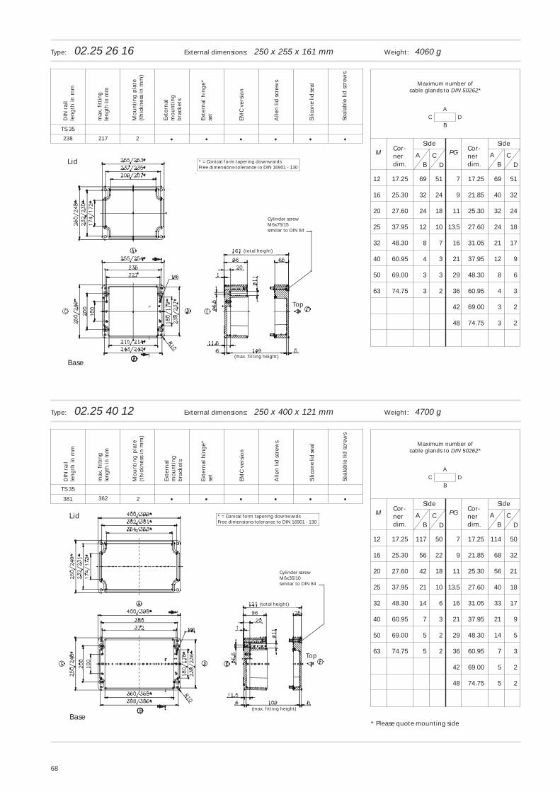
68
C DA
B
CD
M AB
PG
12 17.25 69 51 7 17.25 69 51
16 25.30 32 24 9 21.85 40 32
20 27.60 24 18 11 25.30 32 24
25 37.95 12 10 13.5 27.60 24 18
32 48.30 8 7 16 31.05 21 17
40 60.95 4 3 21 37.95 12 9
50 69.00 3 3 29 48.30 8 6
63 74.75 3 2 36 60.95 4 3
42 69.00 3 2
48 74.75 3 2
CD
AB
Maximum number ofcable glands to DIN 50262*
Cor-nerdim.
Cor-nerdim.
SideSide
Type: 02.25 26 16 External dimensions: 250 x 255 x 161 mm Weight: 4060 g
C DA
B
CD
M AB
PG
12 17.25 117 50 7 17.25 114 50
16 25.30 56 22 9 21.85 68 32
20 27.60 42 18 11 25.30 56 21
25 37.95 21 10 13.5 27.60 40 18
32 48.30 14 6 16 31.05 33 17
40 60.95 7 3 21 37.95 21 9
50 69.00 5 2 29 48.30 14 5
63 74.75 5 2 36 60.95 7 3
42 69.00 5 2
48 74.75 5 2
CD
AB
Maximum number ofcable glands to DIN 50262*
Cor-nerdim.
Cor-nerdim.
SideSide
Type: 02.25 40 12 External dimensions: 250 x 400 x 121 mm Weight: 4700 g
• • ••238
TS 35
•2
• • ••381
TS 35
•2 •
•217
362
DIN
rai
lle
ng
th in
mm
Mo
un
tin
g p
late
(th
ickn
ess
in m
m)
Exte
rnal
mo
un
tin
gb
rack
ets
Exte
rnal
hin
ge*
set
EMC
ver
sio
n
Alle
n li
d s
crew
s
Silic
on
e lid
seal
Seal
able
lid
scr
ews
max
. fit
tin
gle
ng
th in
mm
DIN
rai
lle
ng
th in
mm
Mo
un
tin
g p
late
(th
ickn
ess
in m
m)
Exte
rnal
mo
un
tin
gb
rack
ets
Exte
rnal
hin
ge*
set
EMC
ver
sio
n
Alle
n li
d s
crew
s
Silic
on
e lid
seal
Seal
able
lid
scr
ews
max
. fit
tin
gle
ng
th in
mm
Base
Lid * = Conical form tapering downwardsFree dimensions-tolerance to DIN 16901 - 130
Cylinder screwM6x75/15similar to DIN 84
(total height)
(max. fitting height)
Top
Base
Lid * = Conical form tapering downwardsFree dimensions-tolerance to DIN 16901 - 130
Cylinder screwM6x35/10similar to DIN 84
(total height)
(max. fitting height)
Top
* Please quote mounting side
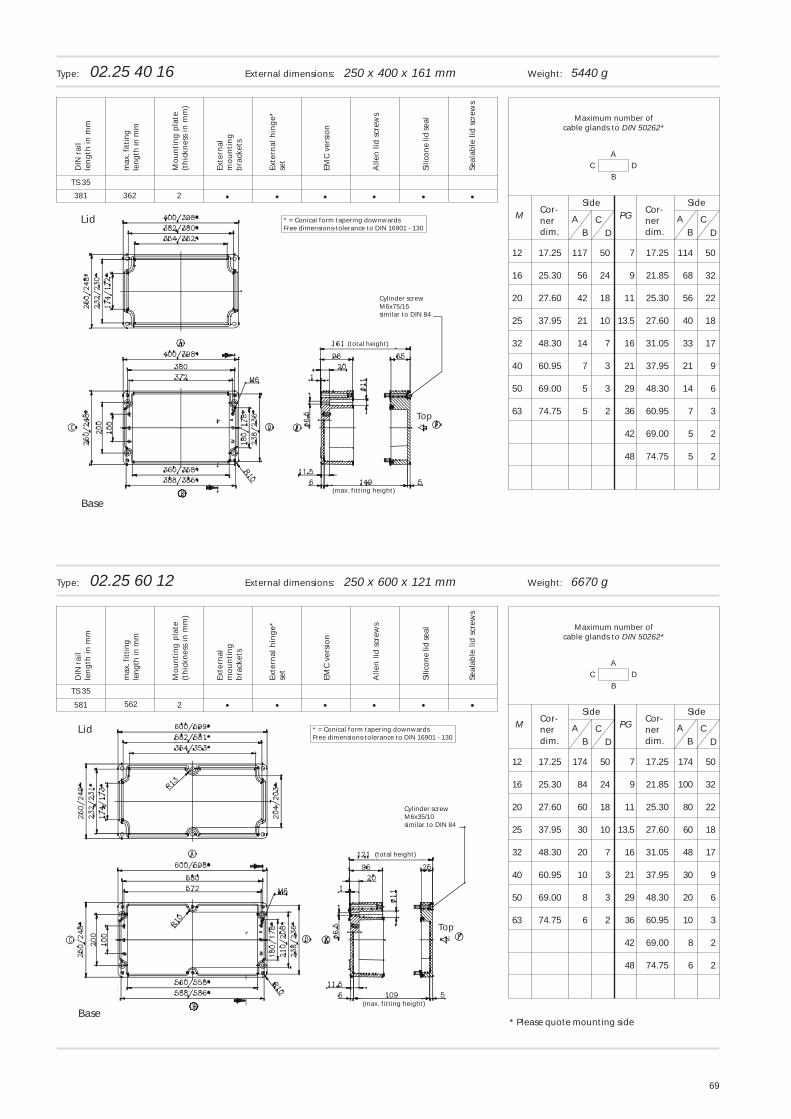
69
C DA
B
CD
M AB
PG
12 17.25 117 50 7 17.25 114 50
16 25.30 56 24 9 21.85 68 32
20 27.60 42 18 11 25.30 56 22
25 37.95 21 10 13.5 27.60 40 18
32 48.30 14 7 16 31.05 33 17
40 60.95 7 3 21 37.95 21 9
50 69.00 5 3 29 48.30 14 6
63 74.75 5 2 36 60.95 7 3
42 69.00 5 2
48 74.75 5 2
CD
AB
Maximum number ofcable glands to DIN 50262*
Cor-nerdim.
Cor-nerdim.
SideSide
Type: 02.25 40 16 External dimensions: 250 x 400 x 161 mm Weight: 5440 g
C DA
B
CD
M AB
PG
12 17.25 174 50 7 17.25 174 50
16 25.30 84 24 9 21.85 100 32
20 27.60 60 18 11 25.30 80 22
25 37.95 30 10 13.5 27.60 60 18
32 48.30 20 7 16 31.05 48 17
40 60.95 10 3 21 37.95 30 9
50 69.00 8 3 29 48.30 20 6
63 74.75 6 2 36 60.95 10 3
42 69.00 8 2
48 74.75 6 2
CD
AB
Maximum number ofcable glands to DIN 50262*
Cor-nerdim.
Cor-nerdim.
SideSide
Type: 02.25 60 12 External dimensions: 250 x 600 x 121 mm Weight: 6670 g
• • ••381
TS 35
•
• • ••581
TS 35
•
2 •
2 •562
362
DIN
rai
lle
ng
th in
mm
Mo
un
tin
g p
late
(th
ickn
ess
in m
m)
Exte
rnal
mo
un
tin
gb
rack
ets
Exte
rnal
hin
ge*
set
EMC
ver
sio
n
Alle
n li
d s
crew
s
Silic
on
e lid
seal
Seal
able
lid
scr
ews
max
. fit
tin
gle
ng
th in
mm
DIN
rai
lle
ng
th in
mm
Mo
un
tin
g p
late
(th
ickn
ess
in m
m)
Exte
rnal
mo
un
tin
gb
rack
ets
Exte
rnal
hin
ge*
set
EMC
ver
sio
n
Alle
n li
d s
crew
s
Silic
on
e lid
seal
Seal
able
lid
scr
ews
max
. fit
tin
gle
ng
th in
mm
Base
Lid * = Conical form tapering downwardsFree dimensions-tolerance to DIN 16901 - 130
Cylinder screwM6x75/15similar to DIN 84
(total height)
(max. fitting height)
Top
Base
Lid * = Conical form tapering downwardsFree dimensions-tolerance to DIN 16901 - 130
Cylinder screwM6x35/10similar to DIN 84
(total height)
(max. fitting height)
Top
* Please quote mounting side
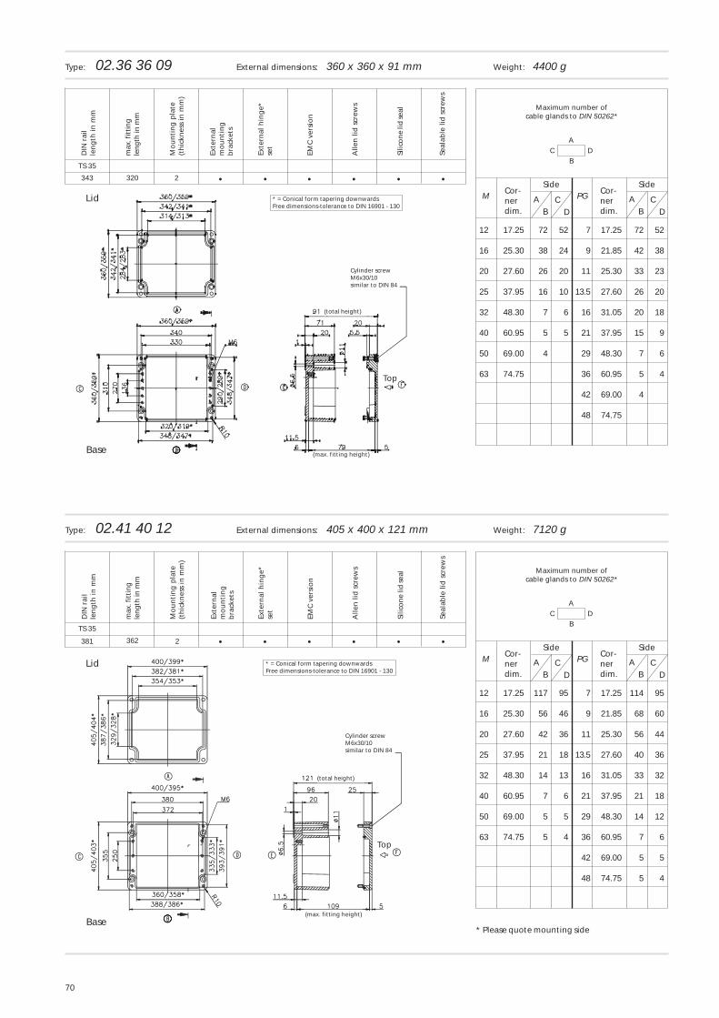
70
C DA
B
CD
M AB
PG
12 17.25 72 52 7 17.25 72 52
16 25.30 38 24 9 21.85 42 38
20 27.60 26 20 11 25.30 33 23
25 37.95 16 10 13.5 27.60 26 20
32 48.30 7 6 16 31.05 20 18
40 60.95 5 5 21 37.95 15 9
50 69.00 4 29 48.30 7 6
63 74.75 36 60.95 5 4
42 69.00 4
48 74.75
CD
AB
Maximum number ofcable glands to DIN 50262*
Cor-nerdim.
Cor-nerdim.
SideSide
Type: 02.36 36 09 External dimensions: 360 x 360 x 91 mm Weight: 4400 g
C DA
B
CD
M AB
PG
12 17.25 117 95 7 17.25 114 95
16 25.30 56 46 9 21.85 68 60
20 27.60 42 36 11 25.30 56 44
25 37.95 21 18 13.5 27.60 40 36
32 48.30 14 13 16 31.05 33 32
40 60.95 7 6 21 37.95 21 18
50 69.00 5 5 29 48.30 14 12
63 74.75 5 4 36 60.95 7 6
42 69.00 5 5
48 74.75 5 4
CD
AB
Maximum number ofcable glands to DIN 50262*
Cor-nerdim.
Cor-nerdim.
SideSide
Type: 02.41 40 12 External dimensions: 405 x 400 x 121 mm Weight: 7120 g
• • ••343
TS 35
•2
• • ••381
TS 35
•2 •
•320
362
DIN
rai
lle
ng
th in
mm
Mo
un
tin
g p
late
(th
ickn
ess
in m
m)
Exte
rnal
mo
un
tin
gb
rack
ets
Exte
rnal
hin
ge*
set
EMC
ver
sio
n
Alle
n li
d s
crew
s
Silic
on
e lid
seal
Seal
able
lid
scr
ews
max
. fit
tin
gle
ng
th in
mm
DIN
rai
lle
ng
th in
mm
Mo
un
tin
g p
late
(th
ickn
ess
in m
m)
Exte
rnal
mo
un
tin
gb
rack
ets
Exte
rnal
hin
ge*
set
EMC
ver
sio
n
Alle
n li
d s
crew
s
Silic
on
e lid
seal
Seal
able
lid
scr
ews
max
. fit
tin
gle
ng
th in
mm
Base
Lid * = Conical form tapering downwardsFree dimensions-tolerance to DIN 16901 - 130
Cylinder screwM6x30/10similar to DIN 84
(total height)
(max. fitting height)
Top
Base
Lid * = Conical form tapering downwardsFree dimensions-tolerance to DIN 16901 - 130
Cylinder screwM6x30/10similar to DIN 84
(total height)
(max. fitting height)
Top
* Please quote mounting side
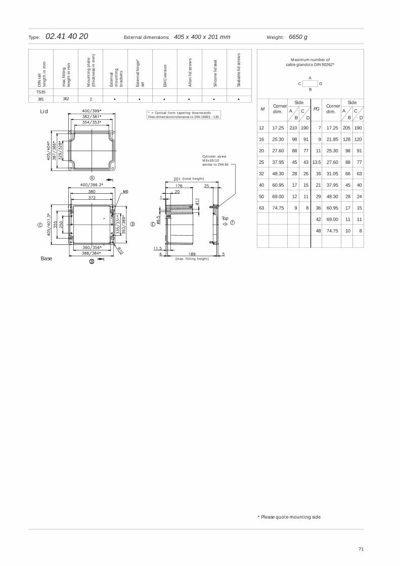
71
C DA
B
CD
M AB
PG
12 17.25 210 190 7 17.25 205 190
16 25.30 98 91 9 21.85 128 120
20 27.60 88 77 11 25.30 98 91
25 37.95 45 43 13.5 27.60 88 77
32 48.30 28 26 16 31.05 66 63
40 60.95 17 15 21 37.95 45 40
50 69.00 12 11 29 48.30 28 24
63 74.75 9 8 36 60.95 17 15
42 69.00 11 11
48 74.75 10 8
CD
AB
Maximum number ofcable glands to DIN 50262*
Cornerdim.
Cornerdim.
SideSide
Type: 02.41 40 20 External dimensions: 405 x 400 x 201 mm Weight: 6650 g
• • ••381
TS 35
•2 •362
DIN
rai
lle
ng
th in
mm
Mo
un
tin
g p
late
(th
ickn
ess
in m
m)
Exte
rnal
mo
un
tin
gb
rack
ets
Exte
rnal
hin
ge*
set
EMC
ver
sio
n
Alle
n li
d s
crew
s
Silic
on
e lid
seal
Seal
able
lid
scre
ws
max
. fitt
ing
len
gth
in m
m
Base
Lid * = Conical form tapering downwardsFree dimensions-tolerance to DIN 16901 - 130
Cylinder screwM6x35/10similar to DIN 84
(total height)
(max. fitting height)
Top
* Please quote mounting side