Embed Size (px)
Citation preview
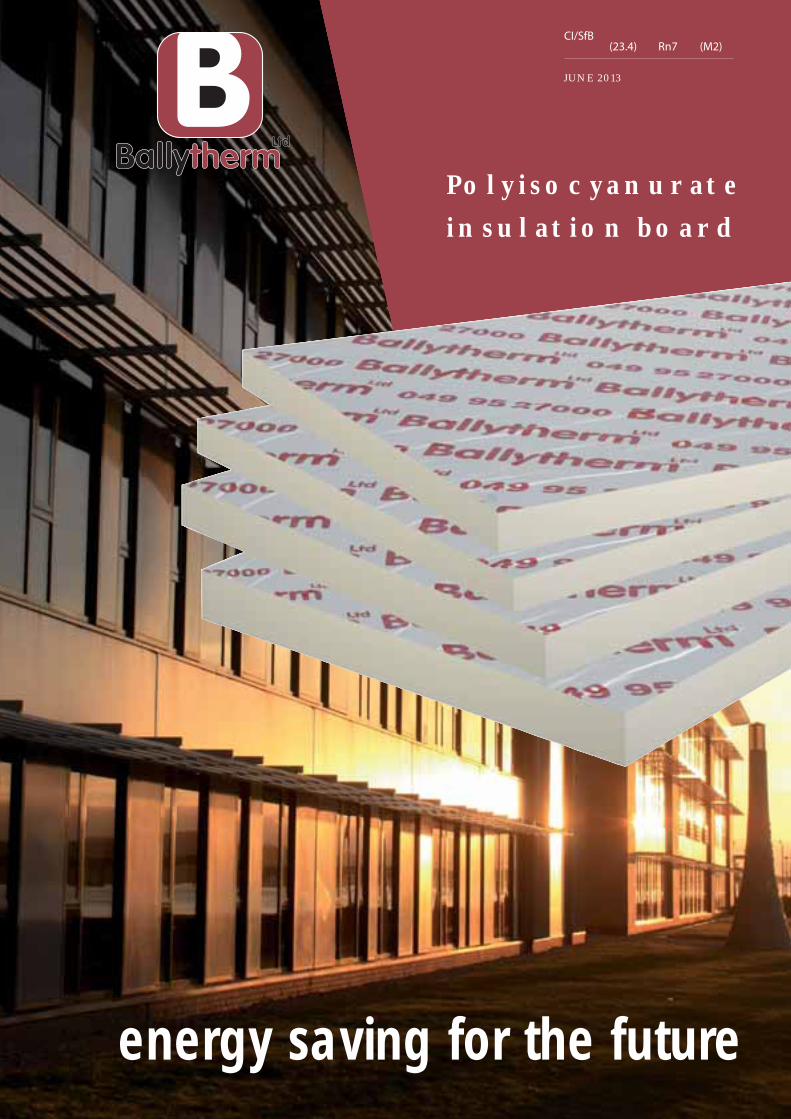
JUNE 2013
CI/SfB(23.4) Rn7 (M2)
Polyisocyanurateinsulation board
energy saving for the future
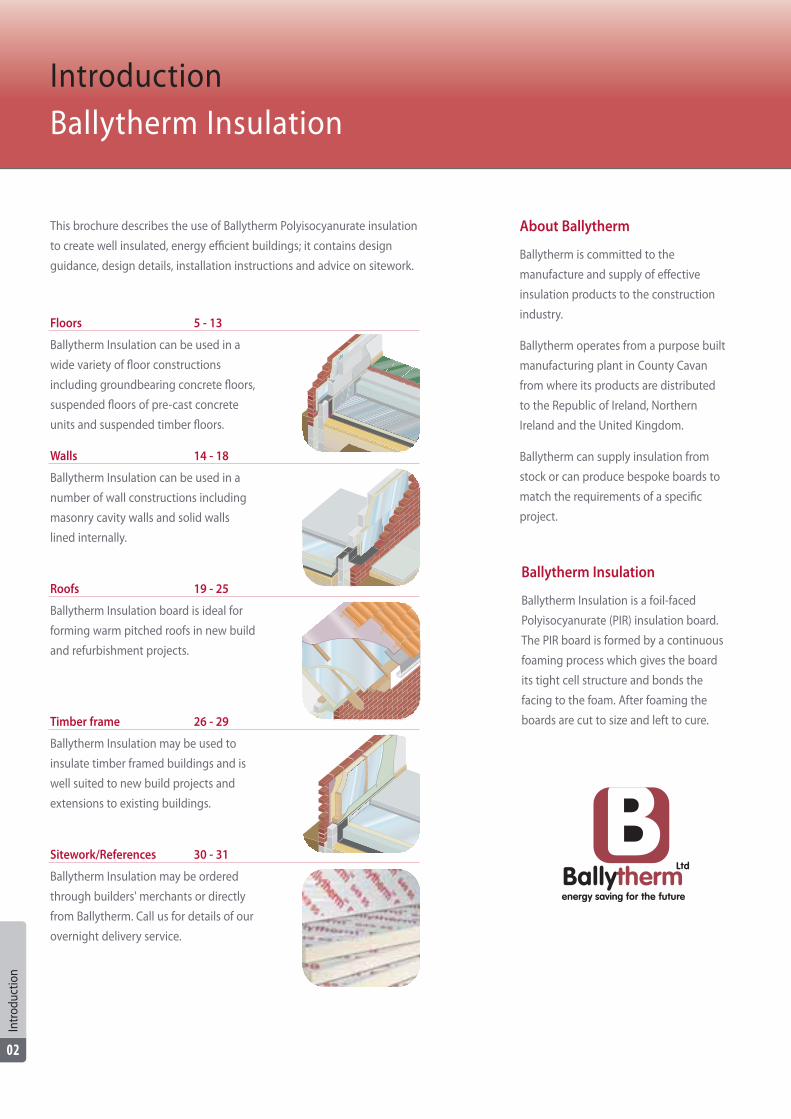
Floors 5 - 13
Ballytherm Insulation can be used in a
wide variety of floor constructions
including groundbearing concrete floors,
suspended floors of pre-cast concrete
units and suspended timber floors.
Walls 14 - 18
Ballytherm Insulation can be used in a
number of wall constructions including
masonry cavity walls and solid walls
lined internally.
Roofs 19 - 25
Ballytherm Insulation board is ideal for
forming warm pitched roofs in new build
and refurbishment projects.
Timber frame 26 - 29
Ballytherm Insulation may be used to
insulate timber framed buildings and is
well suited to new build projects and
extensions to existing buildings.
Sitework/References 30 - 31
Ballytherm Insulation may be ordered
through builders' merchants or directly
from Ballytherm. Call us for details of our
overnight delivery service.
About Ballytherm
Ballytherm is committed to the
manufacture and supply of effective
insulation products to the construction
industry.
Ballytherm operates from a purpose built
manufacturing plant in County Cavan
from where its products are distributed
to the Republic of Ireland, Northern
Ireland and the United Kingdom.
Ballytherm can supply insulation from
stock or can produce bespoke boards to
match the requirements of a specific
project.
IntroductionBallytherm Insulation
This brochure describes the use of Ballytherm Polyisocyanurate insulation
to create well insulated, energy efficient buildings; it contains design
guidance, design details, installation instructions and advice on sitework.
Intr
oduc
tion
02
Ballytherm Insulation
Ballytherm Insulation is a foil-faced
Polyisocyanurate (PIR) insulation board.
The PIR board is formed by a continuous
foaming process which gives the board
its tight cell structure and bonds the
facing to the foam. After foaming the
boards are cut to size and left to cure.
Cavity Wall BoardsLengthWidthThicknesses
mm120045030, 35, 40, 50, 60, 65, 70, 75, 80, 90 & 100
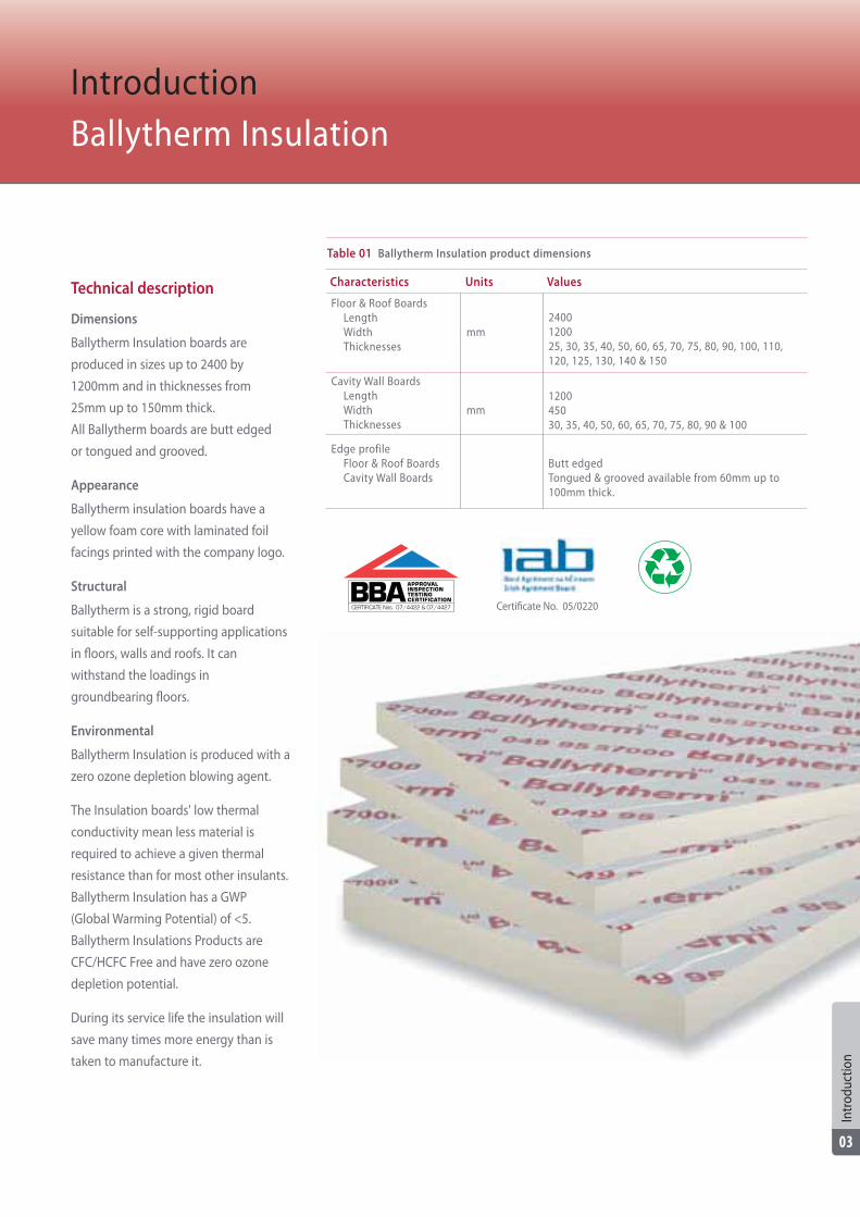
Technical description
Dimensions
Ballytherm Insulation boards are
produced in sizes up to 2400 by
1200mm and in thicknesses from
25mm up to 150mm thick.
All Ballytherm boards are butt edged
or tongued and grooved.
Appearance
Ballytherm insulation boards have a
yellow foam core with laminated foil
facings printed with the company logo.
Structural
Ballytherm is a strong, rigid board
suitable for self-supporting applications
in floors, walls and roofs. It can
withstand the loadings in
groundbearing floors.
Environmental
Ballytherm Insulation is produced with a
zero ozone depletion blowing agent.
The Insulation boards' low thermal
conductivity mean less material is
required to achieve a given thermal
resistance than for most other insulants.
Ballytherm Insulation has a GWP
(Global Warming Potential) of <5.
Ballytherm Insulations Products are
CFC/HCFC Free and have zero ozone
depletion potential.
During its service life the insulation will
save many times more energy than is
taken to manufacture it.
IntroductionBallytherm Insulation
Table 01 Ballytherm Insulation product dimensions
Characteristics Units Values
Floor & Roof BoardsLengthWidthThicknesses
mm2400120025, 30, 35, 40, 50, 60, 65, 70, 75, 80, 90, 100, 110,120, 125, 130, 140 & 150
Edge profileFloor & Roof BoardsCavity Wall Boards
Butt edgedTongued & grooved available from 60mm up to100mm thick.
Certificate No. 05/0220
Intr
oduc
tion
03
CERTIFICATE Nos. 07/4422 & 07/4427
Fire
Ballytherm Insulation remains stable at
temperatures up to 400ºC; at higher
temperatures a protective char forms on
the surface, slowing the spread of flame.
Ballytherm insulation may be used safely
behind non-flammable materials such as
plasterboard; it has achieved a Class 1
surface spread of flame rating when
tested to BS 476-7:1997.
Moisture
The PIR core of Ballytherm Insulation
boards has a low moisture absorption
capacity, making Ballytherm Insulation
suitable for use in damp environments.
The foil laminate facing gives the boards
a high vapour resistance.
Biological
Ballytherm Insulation does not rot and
does not contribute to the growth of
mould, nor does it support insects or
other pests.
Thermal
The PIR core of Ballytherm Insulation
boards has an extremely low thermal
conductivity, making the required
thickness of insulation less than for most
other insulants. The foil laminate facings
of Ballytherm boards can also contribute
to improved thermal performance: the
low emissivity surface of the reflective
foil can cut radiation heat transfer across
an adjoining air space.
Durability
When Ballytherm Insulation is installed
in accordance with manufacturer's
guidance and industry codes of practice
it has a service life comparable to that of
the rest of the building.
IntroductionBallytherm Insulation
Table 02 Performance of Ballytherm Insulation
Properties Standards Units Values
Thermal conductivityFloor, Cavity Wall and Roof boardsDry lining boards (combined)
Compressive strengthFloor boardsCavity wall. Dry lining and Roof boards
Dimensional stability
Water absorption
I.S. EN 12667
EN 826
EN 1604
EN 12087
W/mK
kPa
% vol
0.0220.026
>140CS (10\Y) 50
DS(TH) 6
Foil 1.2
Table 03 Ballytherm Insulation pack sizes and thermal performance
ThicknessSheetsper lift
Floor & Roof Boards25mm30mm 35mm40mm50mm60mm65mm70mm75mm80mm90mm
100mm110mm120mm125mm130mm140mm150mm
5747403528232120181715141211111010
9
1149480705646424036343028242222202018
328.32270.72230.40201.60161.28132.48120.96115.20103.68
97.9286.4080.6469.1263.3663.3657.6057.6051.84
1.136m2K/W1.364m2K/W1.590m2K/W1.818m2K/W2.272m2K/W2.727m2K/W2.955m2K/W3.181m2K/W3.409m2K/W3.636m2K/W4.091m2K/W4.545m2K/W5.000m2K/W5.454m2K/W5.681m2K/W5.909m2K/W6.363m2K/W6.818m2K/W
Sheetsper pallet
m2
per palletThermal
resistance
Intr
oduc
tion
04
ThicknessSheets
per pack
Cavity Wall Boards30mm 35mm40mm50mm60mm65mm70mm75mm80mm90mm
100mm
101111
97766544
Packsper pack
1212121212121212121212
160132132108
84847272604848
86.4071.2871.2858.3245.3645.3638.8838.8832.4025.9225.92
1.364m2K/W1.590m2K/W1.818m2K/W2.272m2K/W2.727m2K/W2.955m2K/W3.181m2K/W3.409m2K/W3.636m2K/W4.091m2K/W4.545m2K/W
Sheetsper pallet
m2
per palletThermal
resistance
Other sizes available on request.
Introduction
Ballytherm Insulation can be used in a
wide variety of floor constructions
including groundbearing concrete floors,
suspended floors of pre-cast concrete
units and suspended timber floors.
Loading
Floor insulation must be able to
withstand the deadload of the floor
construction and the imposed loads
resulting from occupation of the
building. Ballytherm has a sufficiently
high compressive strength for it to be
used in domestic projects.
Consult Ballytherm for advice on using
the material in projects with more
demanding loadings.
Thermal bridging
Improved standards of thermal
insulation within building elements have
focussed attention upon the amount of
heat lost at junctions between elements
where there is no continuity of insulation
or there are exposed heat paths.
The simplest method to avoid thermal
bridging at the floor/wall junction is be
to ensure the insulation in the two
elements meet. Where structural
considerations make that impossible, for
example when the wall insulation is
inside a cavity, thermal bridging may be
avoided by continuing the floor
insulation vertically at the perimeter of
the floor so it overlaps the wall
insulation. The minimum thickness of
Ballytherm boards for edge insulation is
20mm. It is sometimes more convenient
to use the same board thickness as
specified for the rest of the floor.
Thermal performance
U-values for ground floors are calculated
according to EN ISO 13770: 2007.
Because the ground has an innate
thermal resistance the overall thermal
performance of the floor depends upon
the floor's dimensions and form factor,
represented by the ratio P/A (the floor
perimeter, P, divided by the floor area, A)
as well as the insulation and other layers
in the construction.
The thickness of Ballytherm Insulation
required to meet the U-values required
by regulations is shown in tables 04 to
07. To use the tables, calculate the ratio
P/A and consult the appropriate column
in the table. Contact Ballytherm for
U-value calculations for other floor
constructions.
Building Regulations andStandards
Building Regulations and Building
Standards set targets for the overall
energy efficiency of buildings, as well as
setting limiting U-values for building
elements.
The U-value tables in this brochure
indicate the maximum area-weighted
U-values permitted by local regulations.
However, it may be necessary to achieve
U-values lower than those shown, in
order to attain the whole-building
energy efficiency target.
Radon protection
Radon is a naturally occurring gas which
is generated during the radioactive
decay of uranium to lead. High
concentrations of radon can cause
cancer.
For the most part radon percolating to
the surface disperses harmlessly in the
atmosphere; however, radon generated
beneath buildings can seep in through
gaps and cracks in the structure and
build-up to dangerous concentrations.
To protect building occupants from risk
of harm, buildings in at-risk areas must
include radon protection measures*.
The minimum measure will be the
provision of a radon barrier across the
entire footprint of the building.
The detailing of the barrier will depend
upon the floor construction, but in many
cases one membrane can act as damp-
proof membrane (DPM) and radon
barrier. Difficulties can arise at external
walls, where the radon barrier has to be
carried across a cavity: one solution is to
seal the radon barrier to a gas-proof
damp-proof course (DPC) which is
stepped down from the inner to outer
leaf.
For details of radon protection measures
refer to:
• BR 211. Radon: guidance on
protective measures for new
buildings. 2007.
• Radon in the workplace. A guide for
building owners and managers. 2011.
• HomeBond House Building Manual.
7th edition.
* In the Republic of Ireland all new dwellings
must include a radon barrier. In England and
Wales, Scotland and Northern Ireland radon
protection measures are required in areas
assessed as high risk.
FloorsGeneral considerations
Floo
rs
05
“...is well suited to new build andrefurbishment projects where a
timber floor is to be replaced by a concrete floor...”
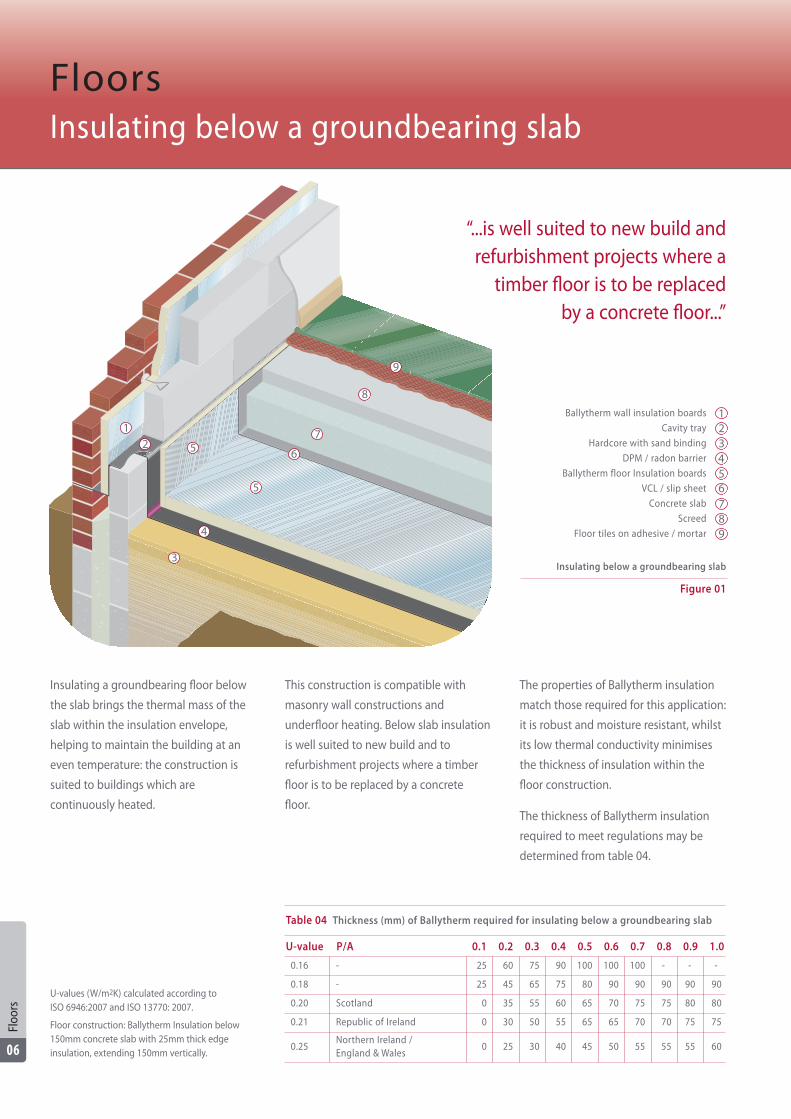
Ballytherm wall insulation boards
Cavity tray
Hardcore with sand binding
DPM / radon barrier
Ballytherm floor Insulation boards
VCL / slip sheet
Concrete slab
Screed
Floor tiles on adhesive / mortar
12
3
4
5 6
7
8
9
Insulating a groundbearing floor below
the slab brings the thermal mass of the
slab within the insulation envelope,
helping to maintain the building at an
even temperature: the construction is
suited to buildings which are
continuously heated.
This construction is compatible with
masonry wall constructions and
underfloor heating. Below slab insulation
is well suited to new build and to
refurbishment projects where a timber
floor is to be replaced by a concrete
floor.
The properties of Ballytherm insulation
match those required for this application:
it is robust and moisture resistant, whilst
its low thermal conductivity minimises
the thickness of insulation within the
floor construction.
The thickness of Ballytherm insulation
required to meet regulations may be
determined from table 04.
FloorsInsulating below a groundbearing slab
Table 04 Thickness (mm) of Ballytherm required for insulating below a groundbearing slab
U-value P/A 0.1 0.2 0.3 0.4 0.5 0.6 0.7 0.8 0.9 1.0
0.16 - 25 60 75 90 100 100 100 - - -
0.18 - 25 45 65 75 80 90 90 90 90 90
0.20 Scotland 0 35 55 60 65 70 75 75 80 80
0.21 Republic of Ireland 0 30 50 55 65 65 70 70 75 75
0.25Northern Ireland / England & Wales
0 25 30 40 45 50 55 55 55 60
U-values (W/m2K) calculated according to ISO 6946:2007 and ISO 13770: 2007.
Floor construction: Ballytherm Insulation below150mm concrete slab with 25mm thick edgeinsulation, extending 150mm vertically.
Figure 01
Insulating below a groundbearing slab
5
123456789
Floo
rs
06
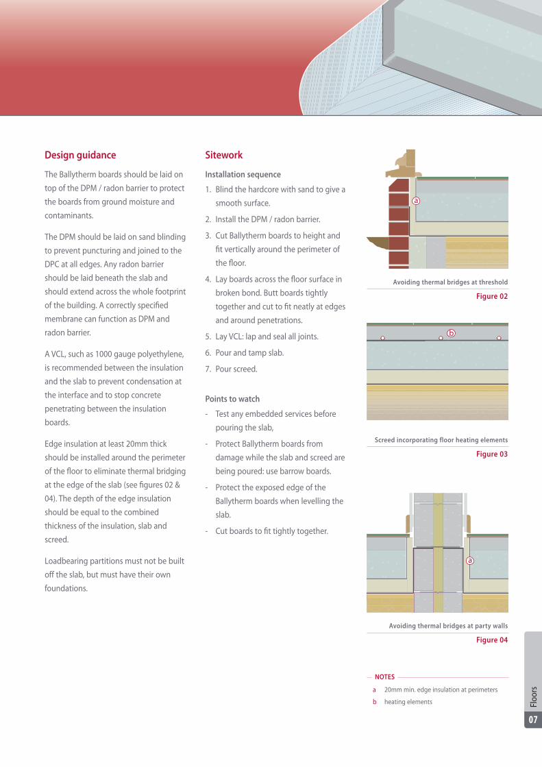
Design guidance
The Ballytherm boards should be laid on
top of the DPM / radon barrier to protect
the boards from ground moisture and
contaminants.
The DPM should be laid on sand blinding
to prevent puncturing and joined to the
DPC at all edges. Any radon barrier
should be laid beneath the slab and
should extend across the whole footprint
of the building. A correctly specified
membrane can function as DPM and
radon barrier.
A VCL, such as 1000 gauge polyethylene,
is recommended between the insulation
and the slab to prevent condensation at
the interface and to stop concrete
penetrating between the insulation
boards.
Edge insulation at least 20mm thick
should be installed around the perimeter
of the floor to eliminate thermal bridging
at the edge of the slab (see figures 02 &
04). The depth of the edge insulation
should be equal to the combined
thickness of the insulation, slab and
screed.
Loadbearing partitions must not be built
off the slab, but must have their own
foundations.
Sitework
Installation sequence
1. Blind the hardcore with sand to give a
smooth surface.
2. Install the DPM / radon barrier.
3. Cut Ballytherm boards to height and
fit vertically around the perimeter of
the floor.
4. Lay boards across the floor surface in
broken bond. Butt boards tightly
together and cut to fit neatly at edges
and around penetrations.
5. Lay VCL: lap and seal all joints.
6. Pour and tamp slab.
7. Pour screed.
Points to watch
- Test any embedded services before
pouring the slab,
- Protect Ballytherm boards from
damage while the slab and screed are
being poured: use barrow boards.
- Protect the exposed edge of the
Ballytherm boards when levelling the
slab.
- Cut boards to fit tightly together.
Figure 02
Avoiding thermal bridges at threshold
Figure 04
Avoiding thermal bridges at party walls
Figure 03
Screed incorporating floor heating elements
NOTES
a 20mm min. edge insulation at perimeters
b heating elements
a
a
b
Floo
rs
07
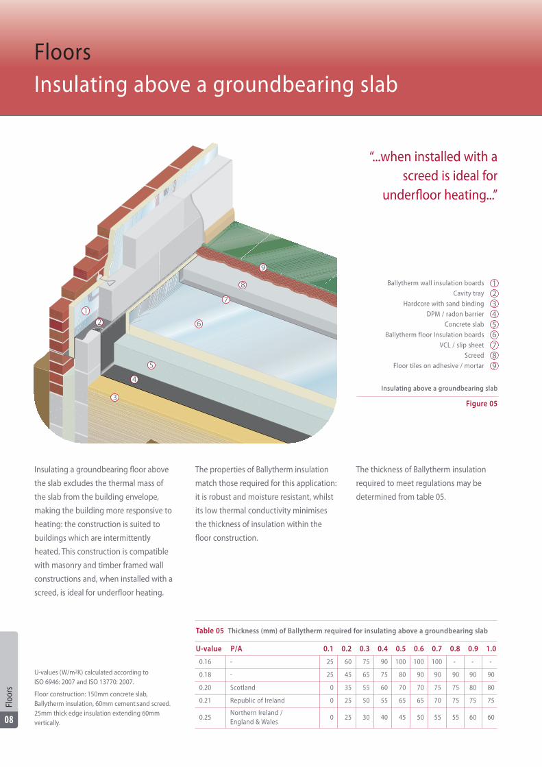
Insulating a groundbearing floor above
the slab excludes the thermal mass of
the slab from the building envelope,
making the building more responsive to
heating: the construction is suited to
buildings which are intermittently
heated. This construction is compatible
with masonry and timber framed wall
constructions and, when installed with a
screed, is ideal for underfloor heating.
The properties of Ballytherm insulation
match those required for this application:
it is robust and moisture resistant, whilst
its low thermal conductivity minimises
the thickness of insulation within the
floor construction.
The thickness of Ballytherm insulation
required to meet regulations may be
determined from table 05.
FloorsInsulating above a groundbearing slab
U-values (W/m2K) calculated according to ISO 6946: 2007 and ISO 13770: 2007.
Floor construction: 150mm concrete slab,Ballytherm insulation, 60mm cement:sand screed.25mm thick edge insulation extending 60mmvertically.
“...when installed with ascreed is ideal for
underfloor heating...”
Ballytherm wall insulation boards
Cavity tray
Hardcore with sand binding
DPM / radon barrier
Concrete slab
Ballytherm floor Insulation boards
VCL / s lip sheet
Screed
Floor tiles on adhesive / mortar
Figure 05
Insulating above a groundbearing slab
123456789
12
3
4
5
6
7
8
9
Floo
rs
08
Table 05 Thickness (mm) of Ballytherm required for insulating above a groundbearing slab
U-value P/A 0.1 0.2 0.3 0.4 0.5 0.6 0.7 0.8 0.9 1.0
0.16 - 25 60 75 90 100 100 100 - - -
0.18 - 25 45 65 75 80 90 90 90 90 90
0.20 Scotland 0 35 55 60 70 70 75 75 80 80
0.21 Republic of Ireland 0 25 50 55 65 65 70 75 75 75
0.25Northern Ireland / England & Wales
0 25 30 40 45 50 55 55 60 60
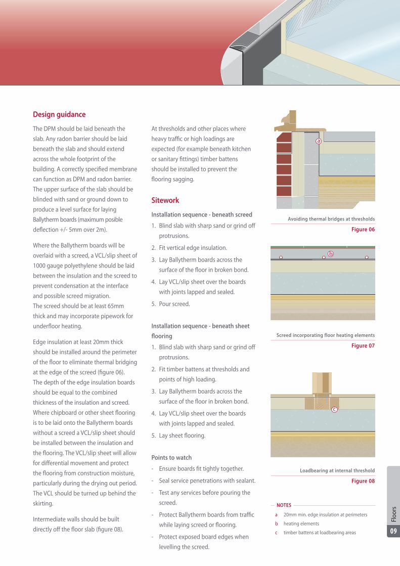
Design guidance
The DPM should be laid beneath the
slab. Any radon barrier should be laid
beneath the slab and should extend
across the whole footprint of the
building. A correctly specified membrane
can function as DPM and radon barrier.
The upper surface of the slab should be
blinded with sand or ground down to
produce a level surface for laying
Ballytherm boards (maximum posible
deflection +/- 5mm over 2m).
Where the Ballytherm boards will be
overlaid with a screed, a VCL/slip sheet of
1000 gauge polyethylene should be laid
between the insulation and the screed to
prevent condensation at the interface
and possible screed migration.
The screed should be at least 65mm
thick and may incorporate pipework for
underfloor heating.
Edge insulation at least 20mm thick
should be installed around the perimeter
of the floor to eliminate thermal bridging
at the edge of the screed (figure 06).
The depth of the edge insulation boards
should be equal to the combined
thickness of the insulation and screed.
Where chipboard or other sheet flooring
is to be laid onto the Ballytherm boards
without a screed a VCL/slip sheet should
be installed between the insulation and
the flooring. The VCL/slip sheet will allow
for differential movement and protect
the flooring from construction moisture,
particularly during the drying out period.
The VCL should be turned up behind the
skirting.
Intermediate walls should be built
directly off the floor slab (figure 08).
At thresholds and other places where
heavy traffic or high loadings are
expected (for example beneath kitchen
or sanitary fittings) timber battens
should be installed to prevent the
flooring sagging.
Sitework
Installation sequence - beneath screed
1. Blind slab with sharp sand or grind off
protrusions.
2. Fit vertical edge insulation.
3. Lay Ballytherm boards across the
surface of the floor in broken bond.
4. Lay VCL/slip sheet over the boards
with joints lapped and sealed.
5. Pour screed.
Installation sequence - beneath sheet
flooring
1. Blind slab with sharp sand or grind off
protrusions.
2. Fit timber battens at thresholds and
points of high loading.
3. Lay Ballytherm boards across the
surface of the floor in broken bond.
4. Lay VCL/slip sheet over the boards
with joints lapped and sealed.
5. Lay sheet flooring.
Points to watch
- Ensure boards fit tightly together.
- Seal service penetrations with sealant.
- Test any services before pouring the
screed.
- Protect Ballytherm boards from traffic
while laying screed or flooring.
- Protect exposed board edges when
levelling the screed.
Figure 06
Avoiding thermal bridges at thresholds
Figure 07
Figure 08
Loadbearing at internal threshold
Screed incorporating floor heating elements
NOTES
a 20mm min. edge insulation at perimeters
b heating elements
c timber battens at loadbearing areas
b
c
a
Floo
rs
09
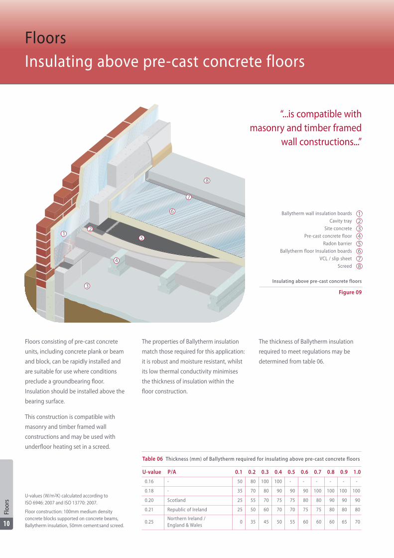
Floors consisting of pre-cast concrete
units, including concrete plank or beam
and block, can be rapidly installed and
are suitable for use where conditions
preclude a groundbearing floor.
Insulation should be installed above the
bearing surface.
This construction is compatible with
masonry and timber framed wall
constructions and may be used with
underfloor heating set in a screed.
The properties of Ballytherm insulation
match those required for this application:
it is robust and moisture resistant, whilst
its low thermal conductivity minimises
the thickness of insulation within the
floor construction.
The thickness of Ballytherm insulation
required to meet regulations may be
determined from table 06.
FloorsInsulating above pre-cast concrete floors
U-values (W/m2K) calculated according to ISO 6946: 2007 and ISO 13770: 2007.
Floor construction: 100mm medium densityconcrete blocks supported on concrete beams,Ballytherm insulation, 50mm cement:sand screed.
“...is compatible withmasonry and timber framed
wall constructions...”
Ballytherm wall insulation boards
Cavity tray
Site concrete
Pre-cast concrete floor
Radon barrier
Ballytherm floor Insulation boards
VCL / slip sheet
Screed
Figure 09
Insulating above pre-cast concrete floors
12345678
12
3
4
5
6
7
8
Floo
rs
10
Table 06 Thickness (mm) of Ballytherm required for insulating above pre-cast concrete floors
U-value P/A 0.1 0.2 0.3 0.4 0.5 0.6 0.7 0.8 0.9 1.0
0.16 - 50 80 100 100 - - - - - -
0.18 - 35 70 80 90 90 90 100 100 100 100
0.20 Scotland 25 55 70 75 75 80 80 90 90 90
0.21 Republic of Ireland 25 50 60 70 70 75 75 80 80 80
0.25Northern Ireland / England & Wales
0 35 45 50 55 60 60 60 65 70
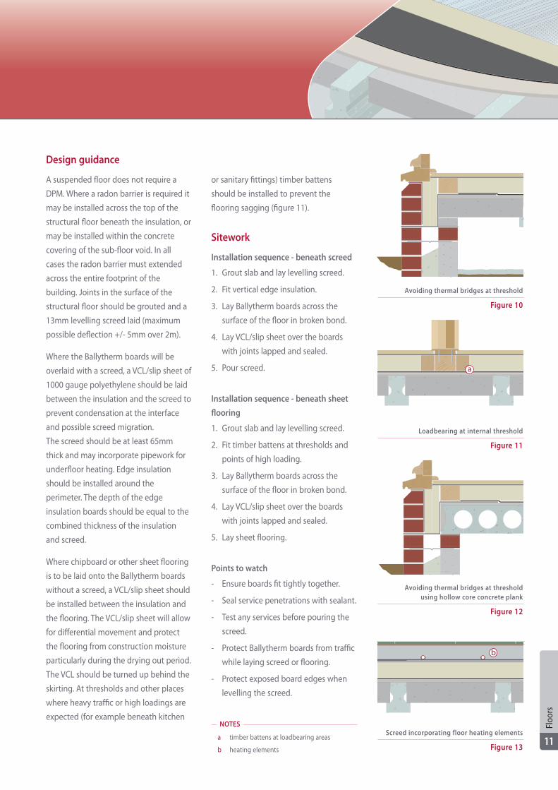
Design guidance
A suspended floor does not require a
DPM. Where a radon barrier is required it
may be installed across the top of the
structural floor beneath the insulation, or
may be installed within the concrete
covering of the sub-floor void. In all
cases the radon barrier must extended
across the entire footprint of the
building. Joints in the surface of the
structural floor should be grouted and a
13mm levelling screed laid (maximum
possible deflection +/- 5mm over 2m).
Where the Ballytherm boards will be
overlaid with a screed, a VCL/slip sheet of
1000 gauge polyethylene should be laid
between the insulation and the screed to
prevent condensation at the interface
and possible screed migration.
The screed should be at least 65mm
thick and may incorporate pipework for
underfloor heating. Edge insulation
should be installed around the
perimeter. The depth of the edge
insulation boards should be equal to the
combined thickness of the insulation
and screed.
Where chipboard or other sheet flooring
is to be laid onto the Ballytherm boards
without a screed, a VCL/slip sheet should
be installed between the insulation and
the flooring. The VCL/slip sheet will allow
for differential movement and protect
the flooring from construction moisture
particularly during the drying out period.
The VCL should be turned up behind the
skirting. At thresholds and other places
where heavy traffic or high loadings are
expected (for example beneath kitchen
or sanitary fittings) timber battens
should be installed to prevent the
flooring sagging (figure 11).
Sitework
Installation sequence - beneath screed
1. Grout slab and lay levelling screed.
2. Fit vertical edge insulation.
3. Lay Ballytherm boards across the
surface of the floor in broken bond.
4. Lay VCL/slip sheet over the boards
with joints lapped and sealed.
5. Pour screed.
Installation sequence - beneath sheet
flooring
1. Grout slab and lay levelling screed.
2. Fit timber battens at thresholds and
points of high loading.
3. Lay Ballytherm boards across the
surface of the floor in broken bond.
4. Lay VCL/slip sheet over the boards
with joints lapped and sealed.
5. Lay sheet flooring.
Points to watch
- Ensure boards fit tightly together.
- Seal service penetrations with sealant.
- Test any services before pouring the
screed.
- Protect Ballytherm boards from traffic
while laying screed or flooring.
- Protect exposed board edges when
levelling the screed.
Figure 11
Loadbearing at internal threshold
Figure 12
Avoiding thermal bridges at thresholdusing hollow core concrete plank
Figure 10
Avoiding thermal bridges at threshold
Figure 13
Screed incorporating floor heating elementsNOTES
a timber battens at loadbearing areas
b heating elements
a
b
Floo
rs
11
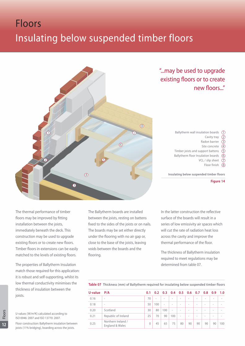
The thermal performance of timber
floors may be improved by fitting
installation between the joists,
immediately beneath the deck. This
construction may be used to upgrade
existing floors or to create new floors.
Timber floors in extensions can be easily
matched to the levels of existing floors.
The properties of Ballytherm Insulation
match those required for this application:
it is robust and self-supporting, whilst its
low thermal conductivity minimises the
thickness of insulation between the
joists.
The Ballytherm boards are installed
between the joists, resting on battens
fixed to the sides of the joists or on nails.
The boards may be set either directly
under the flooring with no air gap or,
close to the base of the joists, leaving
voids between the boards and the
flooring.
In the latter construction the reflective
surface of the boards will result in a
series of low emissivity air spaces which
will cut the rate of radiation heat loss
across the cavity and improve the
thermal performance of the floor.
The thickness of Ballytherm insulation
required to meet regulations may be
determined from table 07.
FloorsInsulating below suspended timber floors
U-values (W/m2K) calculated according to ISO 6946: 2007 and ISO 13770: 2007.
Floor construction: Ballytherm insulation betweenjoists (11% bridging), boarding across the joists.
Ballytherm wall insulation boards
Cavity tray
Radon barrier
Site concrete
Timber joists and support battens
Ballytherm floor Insulation boards
VCL / slip sheet
Floor finish
Figure 14
Insulating below suspended timber floors
12345678
“...may be used to upgradeexisting floors or to create
new floors...”
1
2
3
4
6
7
8
5
Floo
rs
12
Table 07 Thickness (mm) of Ballytherm required for insulating below suspended timber floors
U-value P/A 0.1 0.2 0.3 0.4 0.5 0.6 0.7 0.8 0.9 1.0
0.16 - 70 - - - - - - - - -
0.18 - 50 100 - - - - - - - -
0.20 Scotland 30 80 100 - - - - - - -
0.21 Republic of Ireland 25 70 90 100 - - - - - -
0.25Northern Ireland / England & Wales
0 45 65 75 80 90 90 90 90 100
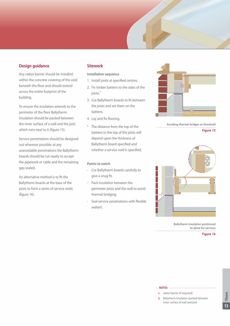
Design guidance
Any radon barrier should be installed
within the concrete covering of the void
beneath the floor and should extend
across the entire footprint of the
building.
To ensure the insulation extends to the
perimeter of the floor Ballytherm
Insulation should be packed between
the inner surface of a wall and the joist
which runs next to it (figure 15).
Service penetrations should be designed
out wherever possible: at any
unavoidable penetrations the Ballytherm
boards should be cut neatly to accept
the pipework or cable and the remaining
gap sealed.
An alternative method is to fit the
Ballytherm boards at the base of the
joists to form a series of service voids
(figure 16).
Sitework
Installation sequence
1. Install joists at specified centres.
2. Fix timber battens to the sides of the
joists.*
3. Cut Ballytherm boards to fit between
the joists and set them on the
battens.
4. Lay and fix flooring.
* The distance from the top of the
battens to the top of the joists will
depend upon the thickness of
Ballytherm board specified and
whether a service void is specified.
Points to watch
- Cut Ballytherm boards carefully to
give a snug fit.
- Pack insulation between the
perimeter joists and the wall to avoid
thermal bridging.
- Seal service penetrations with flexible
sealant.
Figure 15
Avoiding thermal bridges at threshold
Figure 16
Ballytherm Insulation positionedto allow for services
NOTES
a radon barrier (if required)
b Ballytherm Insulation packed between inner surface of wall and joist
a
b
Floo
rs
13
Introduction
Ballytherm insulation can be used in a
number of wall constructions including
masonry cavity walls and internally lined
solid walls.
Moisture
Walls must be designed to prevent
damage to the structure and to the
health of the occupants as a result of
water penetration.
There are three sources of moisture to
consider:
1. To prevent ground moisture rising
into the building, walls must have an
effective DPC which should be joined
to any DPM. Where radon protection
is required the radon barrier must
extend to the outer face of the
external walls: this may be achieved
by using pre-formed cavity trays and
sealing them to the radon barrier
within the cavity. A DPC and radon
barrier should not be set within the
same mortar joint as there is a risk of
creating a slip plane between the two
membranes.
2. Rain driven by the wind onto the
surface of walls can penetrate to the
building's interior. The risk of water
penetration is affected by the severity
of the environmental conditions, the
surface finish and joint treatment, and
the type and positioning of the
insulation.
Because Ballytherm has a very low
thermal resistance, a wall can have
the required thermal performance
with a residual clear cavity without a
great increase in thickness.
Further guidance is given in
BS EN 1996-2: 2006 (with national
annex) and PD 6697: 2010.
3. Water vapour can condense within
walls as it passes from a warm interior
to cold exterior. Ballytherm foil-faced
boards can be of great benefit: in
drylining, the joints between boards
can be sealed with metalised tape to
form a vapour control layer
immediately behind the plasterboard.
Condensation risk analysis should be
carried out for all walls, using the
method in ISO 13788: contact
Ballytherm for details.
Thermal bridging
Maintaining continuity of insulation at
the wall/roof junction can be difficult to
achieve: with cold roofs (insulation
between and above ceiling joists) fibrous
insulation should be pushed between
the rafters onto the wall head. In warm
roofs (with rigid insulation in the plane
of the rafters) Ballytherm insulation may
be extended vertically from the wall
head, between the rafters, to the
underside of the roof insulation.
Openings should be detailed to ensure
insulation meets door and window
frames: setting the windows and doors
behind reveals makes it easier to butt
insulation to the framing and enables a
better seal at the junction of the frame
and wall.
Fixings which penetrate wall insulation,
such as wall ties or screws, will reduce
the thermal performance of the
insulation layer: the use of stainless steel
fixings or plastic ties and fixings with
small cross-sectional areas will minimise
the effect.
Heating flues
Where flues from boilers and other
heating appliances penetrate the walls
precautions must be taken to avoid the
hot pipe coming into contact with the
insulation. There should either be a
25mm gap between the insulation and
the flue - provided by a pipe sleeve - or a
combination flue should be specified.
WallsGeneral considerations
Wal
ls
14
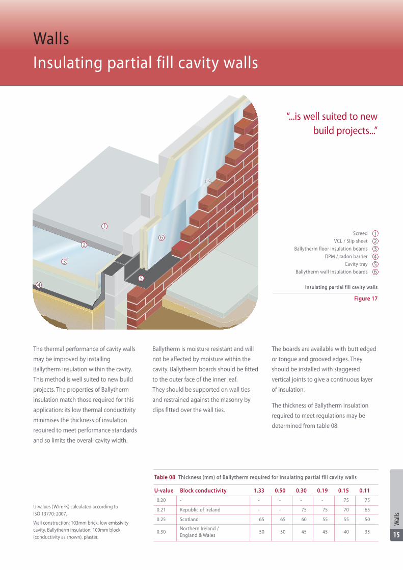
The thermal performance of cavity walls
may be improved by installing
Ballytherm insulation within the cavity.
This method is well suited to new build
projects. The properties of Ballytherm
insulation match those required for this
application: its low thermal conductivity
minimises the thickness of insulation
required to meet performance standards
and so limits the overall cavity width.
Ballytherm is moisture resistant and will
not be affected by moisture within the
cavity. Ballytherm boards should be fitted
to the outer face of the inner leaf.
They should be supported on wall ties
and restrained against the masonry by
clips fitted over the wall ties.
The boards are available with butt edged
or tongue and grooved edges. They
should be installed with staggered
vertical joints to give a continuous layer
of insulation.
The thickness of Ballytherm insulation
required to meet regulations may be
determined from table 08.
WallsInsulating partial fill cavity walls
Table 08 Thickness (mm) of Ballytherm required for insulating partial fill cavity walls
U-value Block conductivity 1.33 0.50 0.30 0.19 0.15 0.11
0.20 - - - - - 75 75
0.21 Republic of Ireland - - 75 75 70 65
0.25 Scotland 65 65 60 55 55 50
0.30Northern Ireland / England & Wales
50 50 45 45 40 35
U-values (W/m2K) calculated according to ISO 13770: 2007.
Wall construction: 103mm brick, low emissivitycavity, Ballytherm insulation, 100mm block(conductivity as shown), plaster.
Screed
VCL / Slip sheet
Ballytherm floor insulation boards
DPM / radon barrier
Cavity tray
Ballytherm wall Insulation boards
Figure 17
Insulating partial fill cavity walls
123456
“...is well suited to newbuild projects...”
1
2
3
4
6
5
Wal
ls
15
Design guidance
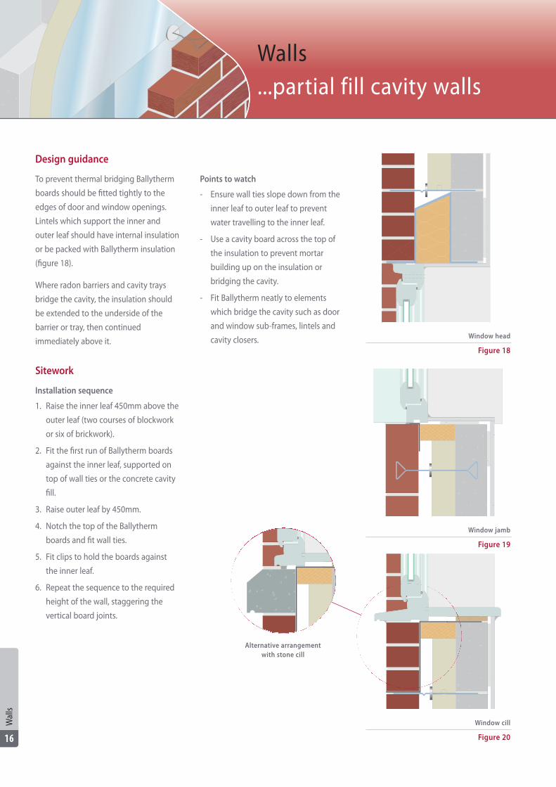
To prevent thermal bridging Ballytherm
boards should be fitted tightly to the
edges of door and window openings.
Lintels which support the inner and
outer leaf should have internal insulation
or be packed with Ballytherm insulation
(figure 18).
Where radon barriers and cavity trays
bridge the cavity, the insulation should
be extended to the underside of the
barrier or tray, then continued
immediately above it.
Sitework
Installation sequence
1. Raise the inner leaf 450mm above the
outer leaf (two courses of blockwork
or six of brickwork).
2. Fit the first run of Ballytherm boards
against the inner leaf, supported on
top of wall ties or the concrete cavity
fill.
3. Raise outer leaf by 450mm.
4. Notch the top of the Ballytherm
boards and fit wall ties.
5. Fit clips to hold the boards against
the inner leaf.
6. Repeat the sequence to the required
height of the wall, staggering the
vertical board joints.
Points to watch
- Ensure wall ties slope down from the
inner leaf to outer leaf to prevent
water travelling to the inner leaf.
- Use a cavity board across the top of
the insulation to prevent mortar
building up on the insulation or
bridging the cavity.
- Fit Ballytherm neatly to elements
which bridge the cavity such as door
and window sub-frames, lintels and
cavity closers.
Walls...partial fill cavity walls
Figure 18
Window head
Figure 19
Window jamb
Figure 20
Window cill
Alternative arrangement with stone cill
Wal
ls
16
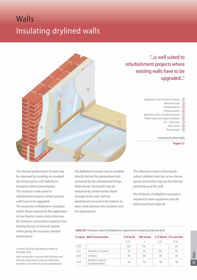
The thermal performance of walls may
be improved by installing an insulated
dry-lining system with Ballytherm
Insulation behind plasterboard.
This method is well suited to
refurbishment projects where existing
walls have to be upgraded.
The properties of Ballytherm insulation
match those required for this application:
its low thermal conductivity minimises
the thickness of insulation required, thus
limiting the loss of internal volume
whilst giving the necessary thermal
performance.
The Ballytherm boards may be installed
directly behind the plasterboard and
restrained by the plasterboard fixings.
Alternatively, the boards may be
restrained by timber battens fixed
through to the wall, with the
plasterboard secured to the battens to
leave voids between the insulation and
the plasterboard.
The reflective surface of the boards
reduce radiation heat loss across the air
spaces and further improve the thermal
performance of the wall.
The thickness of Ballytherm insulation
required to meet regulations may be
determined from table 09.
WallsInsulating drylined walls
Table 09 Thickness (mm) of Ballytherm required for insulating drylined walls
U-value Wall Construction 215 brick 500 stone 215 block 215 aircrete
0.75 2 0.19
-0.20 100 100 - 85
Republic of Ireland0.21 95 95 100 80
Scotland0.25 80 80 80 60
Northern Ireland / England & Wales
0.30 60 60 60 40
U-values (W/m2K) calculated according to ISO 6946: 2007.
Wall construction: masonry wall (thickness andthermal conductivity as shown), Ballytherminsulation, low emissivity cavity, plasterboard.
Ballytherm wall insulation boards
Metalised tape
Timber battens
Existing plaster
Ballytherm floor insulation boards
Timber joists and support battens
VCL / slip sheet
Floor finish
Plasterboard
Figure 21
Insulating drylined walls
123456789
“...is well suited torefurbishment projects where
existing walls have to beupgraded...”
1
2
3
4
6
7
8
5
Wal
ls
17
1.33
9
Design guidance
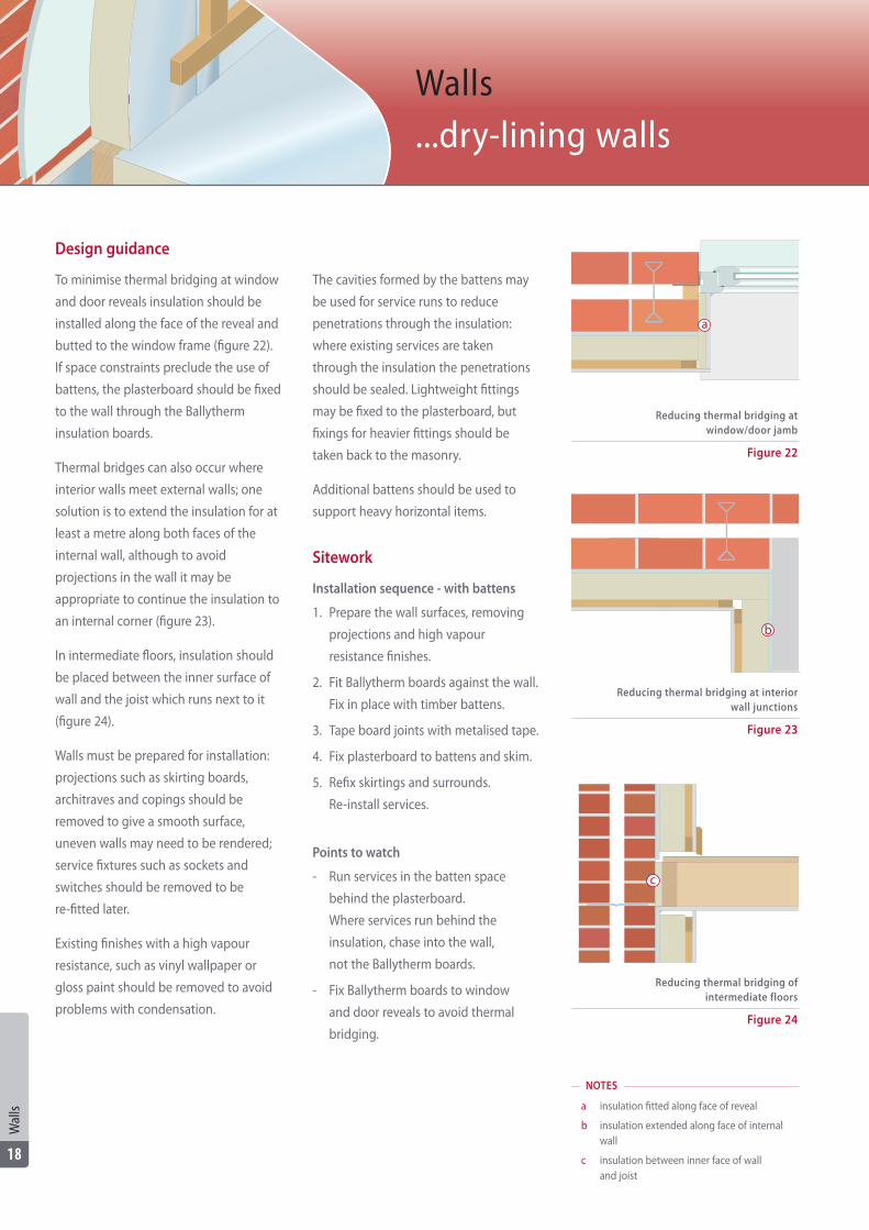
To minimise thermal bridging at window
and door reveals insulation should be
installed along the face of the reveal and
butted to the window frame (figure 22).
If space constraints preclude the use of
battens, the plasterboard should be fixed
to the wall through the Ballytherm
insulation boards.
Thermal bridges can also occur where
interior walls meet external walls; one
solution is to extend the insulation for at
least a metre along both faces of the
internal wall, although to avoid
projections in the wall it may be
appropriate to continue the insulation to
an internal corner (figure 23).
In intermediate floors, insulation should
be placed between the inner surface of
wall and the joist which runs next to it
(figure 24).
Walls must be prepared for installation:
projections such as skirting boards,
architraves and copings should be
removed to give a smooth surface,
uneven walls may need to be rendered;
service fixtures such as sockets and
switches should be removed to be
re-fitted later.
Existing finishes with a high vapour
resistance, such as vinyl wallpaper or
gloss paint should be removed to avoid
problems with condensation.
The cavities formed by the battens may
be used for service runs to reduce
penetrations through the insulation:
where existing services are taken
through the insulation the penetrations
should be sealed. Lightweight fittings
may be fixed to the plasterboard, but
fixings for heavier fittings should be
taken back to the masonry.
Additional battens should be used to
support heavy horizontal items.
Sitework
Installation sequence - with battens
1. Prepare the wall surfaces, removing
projections and high vapour
resistance finishes.
2. Fit Ballytherm boards against the wall.
Fix in place with timber battens.
3. Tape board joints with metalised tape.
4. Fix plasterboard to battens and skim.
5. Refix skirtings and surrounds.
Re-install services.
Points to watch
- Run services in the batten space
behind the plasterboard.
Where services run behind the
insulation, chase into the wall,
not the Ballytherm boards.
- Fix Ballytherm boards to window
and door reveals to avoid thermal
bridging.
Walls...dry-lining walls
Figure 24
Reducing thermal bridging of intermediate floors
Figure 23
Reducing thermal bridging at interiorwall junctions
Figure 22
Reducing thermal bridging atwindow/door jamb
NOTES
a insulation fitted along face of reveal
b insulation extended along face of internal wall
c insulation between inner face of wall and joist
b
c
a
Wal
ls
18
Introduction
In warm roof constructions the insulation
is fitted in the plane of the rafters rather
than at ceiling line.
Warm roofs enable all the space within
the building envelope to be utilised,
whether that means maximising the
usable floor area, creating dramatic
cathedral roofs or simply providing a
controlled environment for running
complex services. Warm roof
construction has benefits for the roof
structure, protecting it from the effects
of wide variations in temperature and
humidity and also increases the racking
strength.
Ballytherm insulation boards are ideal for
forming warm pitched roofs: in new
build the insulation can be fitted over
and between the rafters, or between and
beneath the rafters, while in
refurbishment projects the insulation
can be installed from inside the loft to
upgrade the thermal performance of the
roof without disturbing the existing roof
covering.
General considerations
Structural
The insulation in warm roof applications
must be self-supporting. Where it is laid
across the top of the rafters it must be
able to withstand the imposed loads
from the roof covering transferred
through the counterbattens. Ballytherm
Insulation is strong enough for that
application.
Thermal performance
Ballytherm insulation installed above or
below the rafters is not affected by
thermal bridging by the roof structure,
whereas the thermal performance of an
insulation layer set between the rafters is
reduced by as much as a third.
Although using more insulation above
the rafters will improve the thermal
performance it can create problems: the
forces upon the fixings increase, so more
fixings are required; detailing at eaves
becomes more complex, and it also
becomes more difficult to drive the
fixings accurately into the rafters.
Consequently, it is important to avoid an
excessive amount of insulation above
the rafters by installing some insulation
between the rafters.
Cavities
Where Ballytherm insulation takes up
only part of the rafter depth, the
resulting cavities will each have a low
emissivity surface formed by the
reflective foil face of the board.
Those surfaces will then reduce the rate
of radiation heat transfer across the
cavity and improve the thermal
performance of the roof.
However, in refurbishment projects the
air movement through the cavities will
eliminate much of the benefit from the
low emissivity surface.
Condensation
Roofs must be designed to avoid the
formation of condensation which can
threaten the structural stability of the
roof and promote the growth of mould
and rot. Designers should carry out
condensation risk analysis to assess the
likelihood of problems and modify the
roof design if condensation is predicted.
To reduce condensation risk, designers
should:
- minimise the amount of moisture
entering the roof: moisture generated
by activities such as washing and
cooking should be extracted at source
and a vapour control layer - such as
1000 gauge polyethylene - should be
specified on the warm side of the
insulation.
- ensure any moisture which does enter
can escape to atmosphere: specify a
vapour open underlay which will
allow water vapour to disperse into
the batten space and ensure there is
sufficient air movement between the
batten space and atmosphere (it may
be necessary to vent the batten space
beneath tight coverings such as sheet
metal). In refurbishment projects
where the underlay has a high vapour
resistance there must be a 50mm
vented cavity beneath the underlay.
Further guidance on controlling
condensation may be found in
BS 5250: 2011.
RoofsGeneral considerations
Roof
s
19

Ballytherm insulation may be used to
form warm pitched roofs by applying it
over and between the rafters.
Applying a layer of insulation over the
rafters brings the whole roof within the
insulated envelope and maximises the
available head room. This method is well
suited to new build projects and to
refurbishments where the roof covering
is being stripped off and replaced.
The properties of Ballytherm insulation
match those required for this application:
its low thermal conductivity minimises
the thickness of insulation required,
whilst it is strong enough to support the
loads imposed from the roof covering via
the battens.
The Ballytherm boards should be set in
two layers, one extending in a
continuous layer over the top of the
rafters, which is restrained by
counterbattens, and the second cut to fit
between the rafters and held in place by
battens, clips or partially driven nails.
The insulation is protected by the
internal finish fixed to the underside of
the rafters. The reflective surface of the
boards reduce radiation heat loss across
the air spaces and further improve the
thermal performance of the roof.
The thickness of Ballytherm insulation
required to meet regulations may be
determined from table 10.
Warm RoofInsulating above and between the rafters
Table 10 Thickness (mm) of Ballytherm required for insulating above and between rafters
U-value Above and between
0.14 - 70 + 90
0.16 Republic of Ireland 55 + 95
Above
-
-
0.18 Scotland 50 + 70-
0.20Northern Ireland / England & Wales
50 + 5595
U-values (W/m2K) calculated according to ISO 6946: 2007.
Roof construction: tiles, battens and counterbattencavity, vapour open underlay, Ballytherm board aboverafters, Ballytherm board between rafters (secondcolumn only), low emissivity cavity, plasterboard.
“...is well suited to newbuild projects and to
refurbishments...”
Ballytherm wall insulation boards
Ballytherm roof insulation boardsabove rafters
Stop batten
Counterbatten
Eaves piece
Breather membrane
Roof covering
Figure 25
Insulating above and between the rafters
12
3
45678
1
2
3
4
6
7
8
5
Roof
s
20
Ballytherm roof insulation boards between rafters
Design guidance
Where condensation risk analysis
indicates a risk of condensation a vapour
control layer should be installed behind
the finish.
The underlay should have a vapour
resistance of less than 0.25MNs/g and
may be laid directly over the insulation
or draped over the counterbattens.
A rigid eaves carrier may be required to
prevent ponding and avoid UV
degradation. Counterbattens should be a
minimum of 38 x 50mm and should be
fixed through the Ballytherm boards to
the rafters with fixings such as Helfix
Inscrew or Proctor PR nails: consult the
fixing manufacturer for information on
loadings and spacings. There should be a
stop batten fixed across the rafters at
eaves to prevent the insulation slipping
down the roof.
There is no need to ventilate beneath
the underlay, but there must be
sufficient air movement between the
batten space and outside air to allow
moisture to disperse. Roof coverings
such as tiles and slates will allow enough
air flow through the laps, however, air
spaces beneath tight coverings should
be vented.
To avoid thermal bridging the roof
insulation should meet that in the walls:
if a cavity wall is finished with a closer,
additional insulation should be fitted
from the top of the closer to the upper
face of the rafters, where it will butt the
over-rafter insulation. At verges the wall
insulation should run to the top of the
wall and butt the underside of the over-
rafter insulation which is extended
across the wall head.
At ridges, hips and valleys where roof
planes intersect, the over-rafter
insulation should be cut to form a
continuous layer of insulation. Junctions
may be sealed with expanding foam
insulation.
Sitework
When working at a height ensure risk
assessments have been carried out and
that all necessary protective measures
are in place.
Do not walk on Ballytherm boards nor
use them as a working platform.
Installation sequence (working from
the outside)
1. Fit battens to the sides of the rafters
to support the between rafter
insulation.
2. Cut Ballytherm insulation to fit tightly
between the rafters. Set insulation on
the battens.
3. Fix a stop batten across the ends of
the rafters.
4. Lay the first row of Ballytherm
insulation boards across the rafters,
resting firmly against the stop batten.
Tack in place with clout nails.
5. Lay the next rows of Ballytherm
insulation boards. Stagger board
junctions between rows.
6. Fix counterbattens to the rafters.*
7. Lay the underlay, following
manufacturer's instructions.
8. Install the roof covering
Points to watch
- Cut boards to fit neatly around
penetrations such as SVPs.
- Seal gaps and junctions with
expanding foam.
* where the underlay is installed under
the counterbattens reverse the order
of points 6 and 7.
Figure 26
Eaves
Figure 27
Abutment
Figure 28
Verge
Roof
s
21
Ballytherm insulation may be used to
form warm pitched roofs when applied
between and below the rafters.
Applying a layer of insulation beneath
the rafters avoids the use of long fixings
and enables all the insulation to be
applied from inside the roof.
This method is well suited to new build
projects and to refurbishments where
the roof covering is being stripped off
and replaced.
The properties of Ballytherm insulation
match those required for this application:
its low thermal conductivity minimises
the thickness of insulation required,
whilst it is strong enough to span the
distances between the rafters without
bowing. The Ballytherm boards should
be set in two layers, one set between the
rafters and the second extending in a
continuous layer across the underside of
the rafters and restrained by battens.
The insulation is protected by the
internal finish. The reflective surface of
the boards reduce radiation heat loss
across the air spaces and further improve
the thermal performance of the roof.
The thickness of Ballytherm insulation
required to meet regulations may be
determined from table 11.
Warm RoofsInsulating between and below the rafters
Table 11 Thickness (mm) of Ballytherm required for insulating between and below rafters
U-value Between and below
0.14 - 100 + 60
0.16 Republic of Ireland 100 + 50
0.18 Scotland 100 + 30
0.20Northern Ireland / England & Wales
100 + 25
U-values (W/m2K) calculated according to ISO 6946: 2007.
Roof construction: tiles, batten cavity, vapour openunderlay, Ballytherm board between rafters,Ballytherm board beneath rafters, low emissivitycavity, plasterboard.
Ballytherm wall insulation boards
Ballytherm roof insulation boards beneath rafters
Ballytherm roof insulation boards between rafters
Ballytherm roof insulation infill
Eaves piece
Breather membrane
Figure 29
Insulating between and below the rafters
12
3
456
Roof covering 7
“...is well suited to projectswhere the roof covering
is being stripped offand replaced...”
Roof
s
22
1
2
3
4
6
7
5
Design guidance
Where condensation risk analysis
indicates a risk of condensation a vapour
control layer should be installed behind
the finish. The two layers of insulation
should be in contact to minimise air
movement between them: timber
battens fixed to the sides of the rafters
may be used to restrain the insulation
between the rafters.
The underlay should have a vapour
resistance of less than 0.25MNs/g and
may be draped over the rafters or the
counterbattens. A rigid eaves carrier may
be required to prevent ponding and
avoid UV degradation. There is no need
to ventilate beneath the underlay, but
there must be sufficient air movement
between the batten space and outside
air to allow moisture to disperse:
counterbattens (min. 38 x 50mm) may
be used to form a deep air space above
the underlay. Roof coverings such as tiles
and slates will allow enough air flow
through the laps, however, air spaces
beneath tight coverings should be
vented.
To avoid thermal bridging the roof
insulation should meet the insulation in
the walls: where a cavity wall is finished
with a closer, additional insulation
should be fitted from the top of the
closer to the upper face of the rafters,
where it will butt the Ballytherm
insulation between the rafters (figure
30). At verges the wall insulation should
extend to the top of the wall, the gap
between the wall and the first rafter
should be packed with insulation and
the insulation under the rafter should be
butted and sealed against the wall
(figure 32).
At ridges, hips and valleys where roof
planes intersect, the under-rafter
insulation should be cut to form a
continuous layer of insulation. Junctions
may be sealed with expanding foam
insulation.
Sitework
When working at a height ensure risk
assessments have been carried out and
that all necessary protective measures
are in place. Do not walk on Ballytherm
boards nor use them as a working
platform.
Installation sequence (working from
inside the roof)
1. Fix timber battens to the sides of the
rafters so the space below the battens
matches the thickness of the
Ballytherm Insulation boards.
2. Cut Ballytherm insulation boards to fit
tightly between the rafters. Starting at
eaves, fit the boards between the
rafters, starting at eaves and working
towards the ridge. Push the boards
against the battens.
3. Set Ballytherm boards across the
underside of the rafters in a
continuous layer. Secure with timber
battens. Tape board joints with
Ballytherm metalised tape.
4. Fix plasterboard to the battens and
skim.
Points to watch
- At verges cut and fit Ballytherm
insulation between the wall and first
rafter.
- Cut boards to fit neatly around
penetrations such as SVPs.
- Seal gaps and junctions with
expanding foam.
Figure 30
Eaves
Figure 31
Abutment
Figure 32
Verge
NOTES
a additional insulation to avoid thermal bridging
b insulation between inner face of wall and joist
a
b
Roof
s
23
Ballytherm insulation may be used to
form warm pitched roofs when applied
between and below the rafters.
This method is well suited to loft
conversions and refurbishment projects
where the roof covering is being
retained. The properties of Ballytherm
insulation match those required for this
application: its low thermal conductivity
minimises the thickness of insulation
required, whilst it is strong enough to
span the distances between the rafters
without bowing.
The Ballytherm boards should be set in
two layers, one layer between the rafters
and the second extending across the
underside of the rafters and restrained
by battens. The insulation is protected by
the internal finish fixed to the underside
of the rafters.
The reflective surface of the boards
reduce radiation heat loss across the air
spaces and further improves the thermal
performance of the roof.
The thickness of Ballytherm insulation
required to meet regulations may be
determined from table 12.
Design guidance
Where the existing construction includes
an underlay with a high vapour
resistance, such as a 1F bituminous felt,
there is a risk of condensation forming
on the underside of the underlay and
damaging the roof.
Loft conversionsInsulating between and below the rafters
U-values (W/m2K) calculated according to ISO 6946: 2007.
Roof construction: tiles, batten cavity, bituminousunderlay, ventilated cavity, Ballytherm boardbetween rafters, Ballytherm board beneath rafters,plasterboard.
*For Scotland the lower U-value limit applies if theoriginal roof has a U-value worse than 0.25W/m2K.
Figure 33
Loft conversions
Internal finish
Ballytherm roof insulation boards beneath rafters
Ballytherm roof insulation boards between rafters
Roof underlayRoof covering
1
4
5
67
Ballytherm wall insulation boards 2Ballytherm wall insulation boards
between timber studs3
“...is well suited to loftconversions and refurbishment
projects where the roofcovering is being
retained...”
1
2
3
4
6
7
5
Roof
s
24
Table 12 Thickness (mm) of Ballytherm required for insulating loft conversions
U-value Between and below
0.15 Scotland* 100 + 65
0.18England & Wales / Scotland* /Northern Ireland
100 + 45
0.20 - 100 + 30
0.25 Republic of Ireland 100 + 25
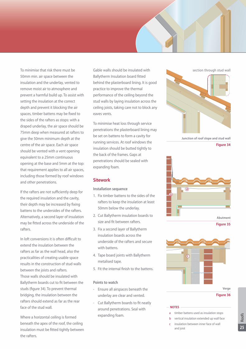
To minimise that risk there must be
50mm min. air space between the
insulation and the underlay, vented to
remove moist air to atmosphere and
prevent a harmful build up. To assist with
setting the insulation at the correct
depth and prevent it blocking the air
spaces, timber battens may be fixed to
the sides of the rafters as stops: with a
draped underlay, the air space should be
75mm deep when measured at rafters to
give the 50mm minimum depth at the
centre of the air space. Each air space
should be vented with a vent opening
equivalent to a 25mm continuous
opening at the base and 5mm at the top:
that requirement applies to all air spaces,
including those formed by roof windows
and other penetrations.
If the rafters are not sufficiently deep for
the required insulation and the cavity,
their depth may be increased by fixing
battens to the undersides of the rafters.
Alternatively, a second layer of insulation
may be fitted across the underside of the
rafters.
In loft conversions it is often difficult to
extend the insulation between the
rafters as far as the wall head, also the
practicalities of creating usable space
results in the construction of stud walls
between the joists and rafters.
Those walls should be insulated with
Ballytherm boards cut to fit between the
studs (figure 34). To prevent thermal
bridging, the insulation between the
rafters should extend as far as the rear
face of the stud wall.
Where a horizontal ceiling is formed
beneath the apex of the roof, the ceiling
insulation must be fitted tightly between
the rafters.
Gable walls should be insulated with
Ballytherm Insulation board fitted
behind the plasterboard lining. It is good
practice to improve the thermal
performance of the ceiling beyond the
stud walls by laying insulation across the
ceiling joists, taking care not to block any
eaves vents.
To minimise heat loss through service
penetrations the plasterboard lining may
be set on battens to form a cavity for
running services. At roof windows the
insulation should be butted tightly to
the back of the frames. Gaps at
penetrations should be sealed with
expanding foam.
Sitework
Installation sequence
1. Fix timber battens to the sides of the
rafters to keep the insulation at least
50mm below the underlay.
2. Cut Ballytherm insulation boards to
size and fit between rafters.
3. Fix a second layer of Ballytherm
insulation boards across the
underside of the rafters and secure
with battens.
4. Tape board joints with Ballytherm
metalised tape.
5. Fit the internal finish to the battens.
Points to watch
- Ensure all airspaces beneath the
underlay are clear and vented.
- Cut Ballytherm boards to fit neatly
around penetrations. Seal with
expanding foam.
Figure 34
Junction of roof slope and stud wall
Figure 35
Abutment
Figure 36
Verge
section through stud wall
NOTES
a timber battens used as insulation stops
b vertical insulation extended up wall face
c insulation between inner face of wall and joist
a
b
c
Roof
s
25
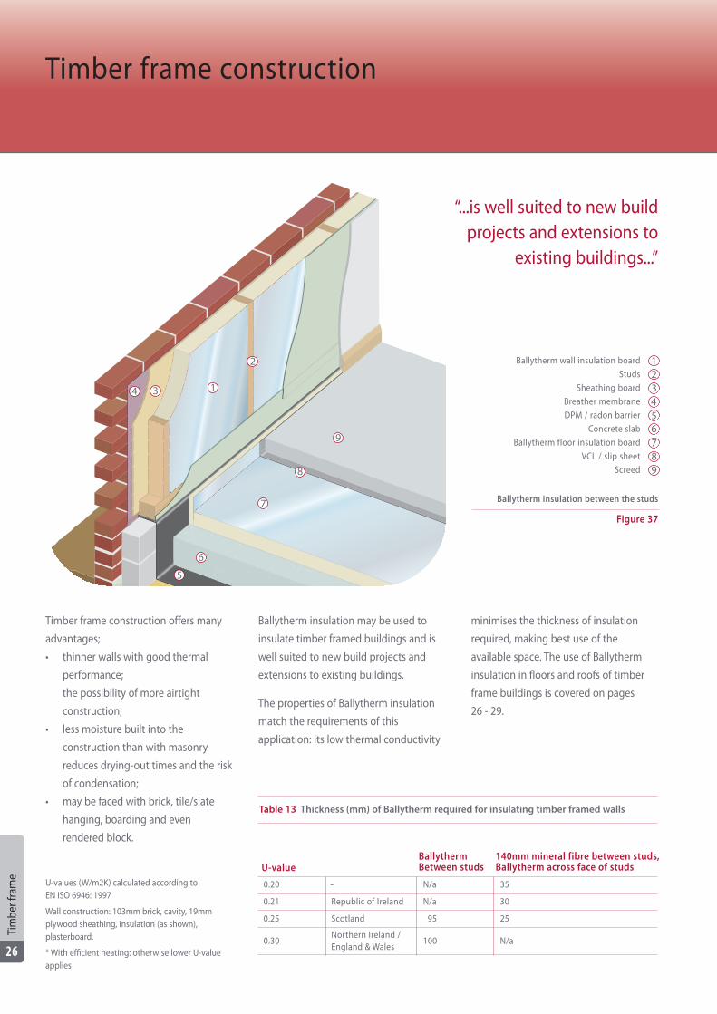
Timber frame construction offers many
advantages;
• thinner walls with good thermal
performance;
the possibility of more airtight
construction;
• less moisture built into the
construction than with masonry
reduces drying-out times and the risk
of condensation;
• may be faced with brick, tile/slate
hanging, boarding and even
rendered block.
Ballytherm insulation may be used to
insulate timber framed buildings and is
well suited to new build projects and
extensions to existing buildings.
The properties of Ballytherm insulation
match the requirements of this
application: its low thermal conductivity
minimises the thickness of insulation
required, making best use of the
available space. The use of Ballytherm
insulation in floors and roofs of timber
frame buildings is covered on pages
26 - 29.
Timber frame construction
Table 13 Thickness (mm) of Ballytherm required for insulating timber framed walls
U-valueBallythermBetween studs
140mm mineral fibre between studs,Ballytherm across face of studs
0.20 - N/a 35
0.21 Republic of Ireland N/a 30
0.25 Scotland 95 25
0.30Northern Ireland / England & Wales
100 N/a
U-values (W/m2K) calculated according to EN ISO 6946: 1997
Wall construction: 103mm brick, cavity, 19mmplywood sheathing, insulation (as shown),plasterboard.
* With efficient heating: otherwise lower U-valueapplies
Ballytherm wall insulation board
Studs
Sheathing board
Breather membrane
DPM / radon barrier
Concrete slab
Ballytherm floor insulation board
VCL / slip sheet
Screed
Figure 37
Ballytherm Insulation between the studs
123456789
“...is well suited to new buildprojects and extensions to
existing buildings...”
1
2
34
6
7
8
9
5
Tim
ber f
ram
e
26
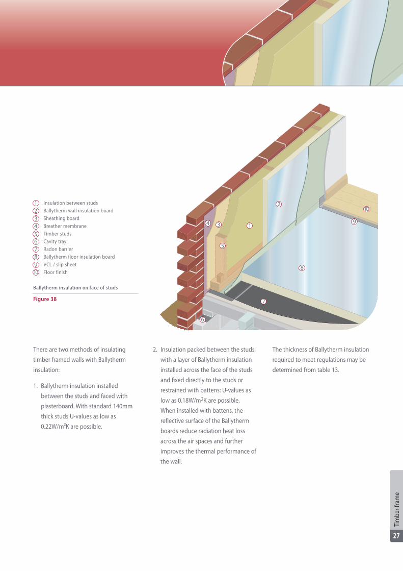
There are two methods of insulating
timber framed walls with Ballytherm
insulation:
1. Ballytherm insulation installed
between the studs and faced with
plasterboard. With standard 140mm
thick studs U-values as low as
0.22W/m²K are possible.
2. Insulation packed between the studs,
with a layer of Ballytherm insulation
installed across the face of the studs
and fixed directly to the studs or
restrained with battens: U-values as
low as 0.18W/m2K are possible.
When installed with battens, the
reflective surface of the Ballytherm
boards reduce radiation heat loss
across the air spaces and further
improves the thermal performance of
the wall.
The thickness of Ballytherm insulation
required to meet regulations may be
determined from table 13.
Insulation between studs
Ballytherm wall insulation board
Sheathing board
Breather membrane
Timber studs
Cavity tray
Radon barrier
Ballytherm floor insulation board
VCL / slip sheet
Floor finish
Figure 38
Ballytherm insulation on face of studs
12345678910
1
2
34
6
7
8
9
5
Tim
ber f
ram
e
27
10
Design guidance
Control of condensation is vital for
timber framed buildings. To prevent the
build up of moisture which can lead to
condensation the designer must:
a. make provision for extracting
moisture at the point of generation
(e.g. bathrooms and kitchens)
b. prevent moisture from entering the
construction, means of a vapour
control layer (VCL)
c. allow moisture within the
construction to pass to atmosphere,
by using materials with high vapour
resistance on the warm side of the
insulation and those with low vapour
resistance on the cold side of the
insulation. To avoid problems which
may arise because of the high vapour
resistance of the plywood
conventionally set on the outside of
the studs, the designer may specify
materials with a lower vapour
resistance, site the plywood on the
inside of the studs or specify a high
performance VCL.
Condensation risk analysis to
EN ISO 13788 should be carried out
for all projects.
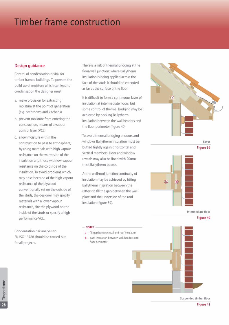
There is a risk of thermal bridging at the
floor/wall junction: where Ballytherm
insulation is being applied across the
face of the studs it should be extended
as far as the surface of the floor.
It is difficult to form a continuous layer of
insulation at intermediate floors, but
some control of thermal bridging may be
achieved by packing Ballytherm
insulation between the wall headers and
the floor perimeter (figure 40).
To avoid thermal bridging at doors and
windows Ballytherm insulation must be
butted tightly against horizontal and
vertical members. Door and window
reveals may also be lined with 20mm
thick Ballytherm boards.
At the wall/roof junction continuity of
insulation may be achieved by fitting
Ballytherm insulation between the
rafters to fill the gap between the wall
plate and the underside of the roof
insulation (figure 39).
Timber frame construction
Figure 39
Eaves
Figure 40
Intermediate floor
Figure 41
Suspended timber floor
NOTES
a fill gap between wall and roof insulation
b pack insulation between wall headers and floor perimeter
a
b b
Tim
ber f
ram
e
28
Design guidance
Fixings which penetrate wall insulation,
such as wall ties or screws, will reduce
the thermal performance of the
insulation layer: the use of stainless steel
fixings or plastic ties and fixings with
small cross-sectional areas will minimise
that effect.
Where flues from boilers and other
heating appliances penetrate the walls
precautions must be taken to avoid the
hot pipe coming into contact with the
insulation. There should either be a
25mm gap between the insulation and
the flue - provided by a pipe sleeve - or a
combination flue should be specified.
Sitework
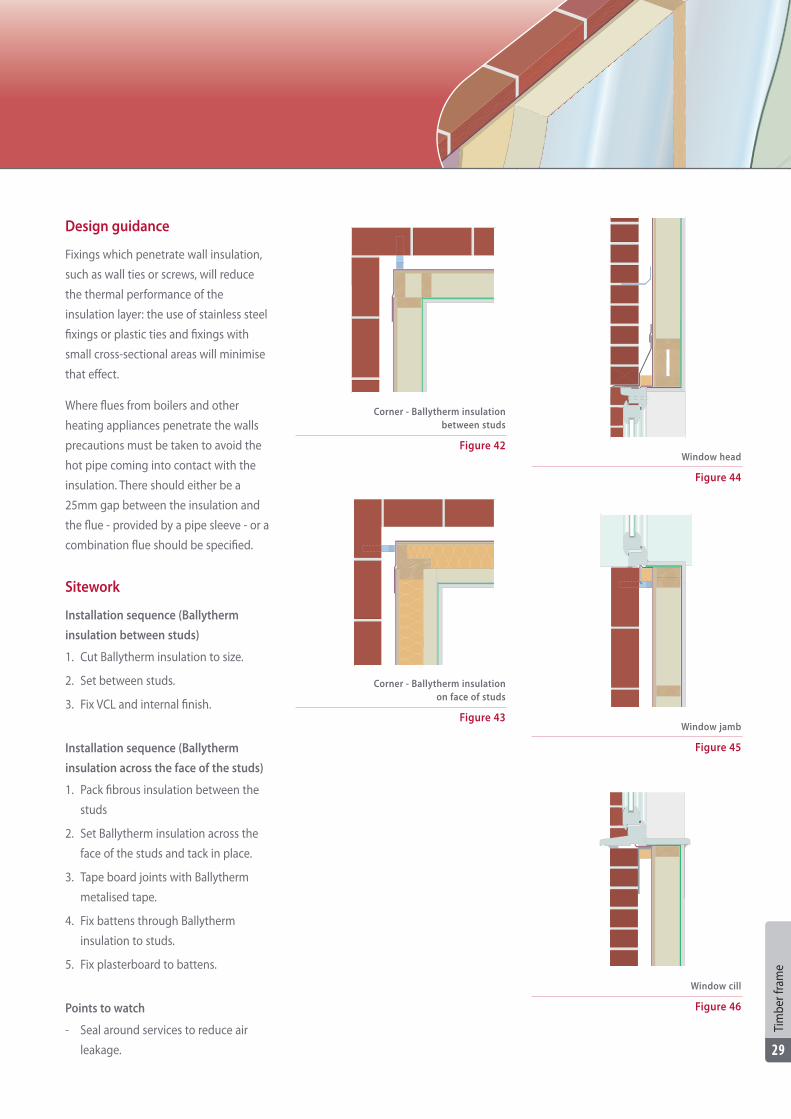
Installation sequence (Ballytherm
insulation between studs)
1. Cut Ballytherm insulation to size.
2. Set between studs.
3. Fix VCL and internal finish.
Installation sequence (Ballytherm
insulation across the face of the studs)
1. Pack fibrous insulation between the
studs
2. Set Ballytherm insulation across the
face of the studs and tack in place.
3. Tape board joints with Ballytherm
metalised tape.
4. Fix battens through Ballytherm
insulation to studs.
5. Fix plasterboard to battens.
Points to watch
- Seal around services to reduce air
leakage.
Figure 46
Window cill
Figure 44
Window head
Figure 45
Window jambFigure 43
Corner - Ballytherm insulation on face of studs
Figure 42
Corner - Ballytherm insulation between studs
Tim
ber f
ram
e
29
Site
wor
k
30
Ballytherm insulation may be ordered
through your local builders' merchants
or distributor.
Ballytherm insulation is supplied in
shrink wrapped packs on pallets.
For pack sizes see table 3.
Handling and storage
Store Ballytherm boards on a level
surface supported on battens.
Protect boards from moisture and
direct sunlight.
Only unpack the quantity of boards
required for the day's work. Take care not
to knock and damage board edges and
corners.
Working
Ballytherm insulation can be worked
with normal hand tools and may be cut
with a fine tooth saw or craft knife.
Where a large amount of cutting is
expected make arrangements for dust
extraction.
Technical support
Ballytherm Ltd. offers designers and
installers a full technical support service
to advise them on the best way of
utilising Ballytherm insulation in new
build and renovation projects.
The service includes:
- Technical literature
- Copies of reports and certificates
- U-value calculations
- Condensation risk analysis
- Design advice
- Samples
- Site visits
Disclaimer: the information contained in
this brochure is based on our best
information at the time of issue, however
Ballytherm Ltd, cannot accept any
responsibility for errors or any liability
out of the use of information provided
on the material supplied.
SiteworkOrdering, supply and delivery
Refe
renc
es
31
References
Building regulations - England and
Wales:
• Approved Document C Site
preparation and resistance to
contaminants and moisture.
• Approved Document L1A
Conservation of fuel and power in
new dwellings.
• Approved Document L1B
Conservation of fuel and power in
existing dwellings.
• Approved Document L2A
Conservation of fuel and power in
new buildings other than dwellings.
• Approved Document L2B
Conservation of fuel and power in
existing buildings other than
dwellings.
Building regulations - Republic of
Ireland
• Technical Guidance Document C - Site
Preparation and Resistance to
Moisture.
• Technical Guidance Document L -
Conservation of Fuel and Energy -
Dwellings.
• Technical Guidance Document L -
Conservation of Fuel and Energy -
Buildings other than dwellings.
Building regulations - Northern Ireland
• Technical booklet C Site preparation
and resistance to moisture.
• Technical booklet F1 Conservation of
fuel and power in dwellings.
• Technical Booklet F2 Conservation of
fuel and power in buildings other
than dwellings.
Building regulations - Scotland
• Technical handbook - domestic
buildings, sections 3 and 6.
• Technical handbook - non-domestic
buildings, sections 3 and 6.
Standards
• BS 5250: 2011. Code of practice for
control of condensation in buildings.
• BS 5534: 2003+A1:2010. Code of
practice for slating and tiling
(including shingles).
• PD 6697: 2010. Recommendations for
the design of masonry structures to
BS EN 1996-1-1 and BS EN 1996-2.
• EN 1604: 1996. Thermal insulating
products for building applications.
Determination of dimensional
stability under specified temperature
and humidity conditions.
• EN 1991-1-4: 2005+A1:2010. Eurocode
1. Actions on structures. General
actions. Wind actions.
• EN 1996-2: 2006. Eurocode 6. Design
of masonry structures. Design
considerations, selection of materials
and execution of masonry.
• EN 826: 2013. Thermal insulating
products for building applications.
Determination of compression
behaviour.
• EN 1606: 2013. Thermal insulating
products for building applications.
Determination of compressive creep.
• EN 12086: 2013. Thermal insulating
products for building applications.
Determination of water vapour
transmission properties.
• EN 12087: 1997. Thermal insulating
products for building applications.
Determination of long term water
absorption by immersion.
• EN 13165: 2012. Thermal insulation
products for buildings. Factory made
rigid polyurethane foam (PUR)
products. Specification.
• EN ISO 6946: 2007. Building
components and building elements.
Thermal resistance and thermal
transmittance. Calculation method.
• EN ISO 13370: 2007. Thermal
performance of buildings.
Heat transfer via the ground.
Calculation methods.
• EN ISO 13788: 2012. Hygrothermal
performance of building components
and building elements - Internal
surface temperature to avoid critical
surface humidity and interstitial
condensation - Calculation methods.
Other guidance
• BRE Digest 465. U-values for light
steel-frame construction.
• BRE 443. Conventions for U-value
calculations. 2006 edition.
• National House Building Council
Standards. NHBC.
• House building manual 7th edition
(Homebond). NHBGS.
• BR 211. Radon: guidance on
protective measures for new
buildings. 2007.
• Radon in the workplace. A guide for
building owners and managers.
BRE. 2011.
References

Ballytherm LtdAnnagh Industrial Park
BallyconnellCo. Cavan
Ireland
Tel: +353 4995 27000Fax: +353 4995 27002
E-mail: [email protected]
www.ballytherm.ie