Embed Size (px)
Citation preview
Communications
692 Ó WILEY-VCH Verlag GmbH, D-69469 Weinheim, 1998 0935-9648/98/0906-0692 $ 17.50+.50/0 Adv. Mater. 1998, 10, No. 9
[16] A. I. Prokofev, S. P. Solodovnikov, D. Kh. Rasuleva, A. A. Volodkin,V. V. Ershov, Izv. Akad. Nauk SSSR, Ser. Khim. 1970, 7, 1656.
[17] L. I. Kudinova, A. A. Volodkin, V. V. Ershov, A. I. Prokofev, Izv.Akad. Nauk SSSR, Ser. Khim. 1978, 7, 1503.
[18] F. N. Merete, S. Spriggs, J. H. P. Utley, Y. Gao, J. Chem. Soc., Chem.Commun. 1994, 11, 1395.
[19] M. O. F. Goulart, J. H. P. Utley, J. Org. Chem. 1988, 53, 2520.[20] J. Veciana, A. D. Martinez, O. Armet, Rev. Chem. Intermed. 1988, 10,
35.[21] S. J. Jacobs, D. A. Shultz, R. Jain, J. Novak, D. A. Dougherty, J. Am.
Chem. Soc. 1993, 115, 1744.[22] P. G. Wenthold, J. B. Kim, W. C. Lineberger, J. Am. Chem. Soc. 1997,
119, 1354.[23] S. A. Miller, California Institute of Technology, unpublished results.
See also: V. Percec, S. Okita, J. Polym. Sci., Part A: Polym. Chem.1993, 31, 877.
[24] R. L. Carlin, Magnetochemistry, Springer, New York 1986.[25] S. J. Jacobs, Ph.D. Thesis, California Institute of Technology 1994.[26] The likely cause of the increased background current is partial clog-
ging of the frit between the counter and working cells, caused by oxi-dation of the electrolyte solution at the counter electrode. Typicallythis is avoided [27] by the use of sacrificial ferrocene in the countercell, but for obvious reasons we could not afford the possibility of Fecontamination.
[27] Organic Electrochemistry (Eds: M. M. Baizer, H. Lund), Marcel Dek-ker, New York 1983.
[28] C. K. Mann, Electroanal. Chem. 1969, 3, 57.[29] C. K. Mann, K. K. Barnes, Electrochemical Reactions in Nonaqueous
Systems, Marcel Dekker, New York 1970.
Polymer p-i-n Junction Photovoltaic Cells**
By Jun Gao, Gang Yu, and Alan J. Heeger*
In this communication, polymer p-i-n junction photovol-taic cells are described in which the p-i-n junction is gener-ated by electrochemical doping and subsequently stabilizedin the frozen junction mode. As in inorganic p-n junctiondevices, the built-in potential arises from the difference inelectrochemical potentials of the p-doped and n-doped re-gions of the active material. Consequently, the device per-formance is not sensitive to electrode materials or to filmthickness. High conversion efficiency can be achieved byusing polymer donor±acceptor blends as the active materi-als.
Polymer-based photovoltaic cells continue to be ofinterest because of the potential for making large-area,flexible, and low-cost solar cells.[1±21] Many conjugatedpolymers have been found to show the photovoltaic effect,including polyacetylenes,[1±7] polythiophene and its deriva-tives,[8±10] and poly(phenylene vinylene) (PPV) and itsderivatives.[11±13] Depending on materials and the cell con-
figuration, the polymer photovoltaic effect has been attrib-uted to metal/polymer Schottky barriers,[1±11] metal-insula-tor-metal (MIM) structures,[12,13] and heterojunctions.[15,19]
For photovoltaic cells made of single polymers, efficienciesare commonly very low as a result of poor charge separa-tion and/or a small built-in field.
The discovery of ultra-fast photo-induced charge transferbetween conjugated polymers (donor, D) and fullerene(C60) (acceptor, A) provides a route to high efficiencyphotovoltaic conversion.[14] Since the charge transfer takesplace about 1000 times faster than the radiative and/ornon-radiative decay of photoexcitations, the quantum effi-ciency for charge transfer and charge separation in such D/A blends is near unity. Efficient photovoltaic cells havebeen made from phase-separated composites of solubleconjugated polymers and C60 as well as from phase-sepa-rated D/A polymer blends. An important step towards highefficiency conversion involves the formation of bicontinu-ous networks; the D/A composites function as bulk hetero-junction materials with carrier collection efficiency as highas 29 % and power conversion efficiency near 3 %.[16±21]
Although the quantum efficiency for photo-inducedcharge separation is near unity for a D/A pair, the separat-ed electrons and holes must be collected by opposite elec-trodes under a built-in electric field. For photovoltaic cellsmade of D/A blends, the polymers are not intentionallydoped, and there is no ground-state electron transfer be-tween donors and acceptors. Under these circumstances,the built-in potential (Vbi) is approximately equal to theenergy difference between the anode and the LUMO ofthe acceptor (for cells made of a pure semiconducting poly-mer, Vbi is equal to the workfunction difference betweenthe two electrodes).
Polymer light-emitting electrochemical cells (LECs) pro-vide a new approach to the fabrication of polymer light-emitting devices.[22±29] In polymer LECs, a solid-state poly-mer electrolyte and the semiconducting polymer form a bi-continuous interpenetrating network (IPN).[24] When a biasgreater than the bandgap is applied, electrochemical redoxoccurs, and a dynamic p-i-n junction is created in situ. Poly-mer LECs exhibit advantages such as low light turn-onvoltage, insensitivity to electrode materials, and relativelyhigh quantum efficiency. In initial studies, the p-i-n junctionformed in LECs was dynamic, i.e., when the external biaswas removed, the junction relaxed and disappeared. Re-cent work has demonstrated, however, that by lowering thetemperature below the glass transition temperature (Tg) ofthe ion-transport polymer, the p-i-n junction formed in situat room can be ªfrozenº, or stabilized.[28] Because of thestabilized p-i-n junction, photovoltaic measurements werecarried out for the first time on a LEC; the built-in poten-tial of the p-i-n polymer diode was approximately 1.3 V.[28]
In this communication, we demonstrate a new deviceconfiguration, polymer p-i-n junction photovoltaic cells, inwhich a blend of poly[5-(2¢-ethylhexyloxy)-2-methoxy-1,4-phenylene vinylene] (MEH-PPV) and cyano-PPV (CN-
±
[*] Prof. A. J. Heeger, Dr. J. GaoInstitute for Polymers and Organic SolidsUniversity of CaliforniaSanta Barbara, CA 93106 (USA)
Prof. A. J. Heeger, Dr. G. YuUNIAX Corporation6780 Cortona Drive, Santa Barbara, CA 93117 (USA)
[**] This work was supported by the National Science Foundation underGrant No. ECE-9528204. The authors thank Dr. Fumitomo Hide forvaluable discussions.
PPV)[21] functions as the donor±acceptor IPN and as thephotoactive medium that facilitates charge separation. Thereversible diode behavior and the photovoltaic responseclearly reveal the p-i-n junction nature of these thin-filmsolid-state devices. The relatively low resistance of the p-and n-doped regions reduces the series resistance andthereby enhances the collection efficiency.
The preparation and the operation of the photovoltaicdevices are similar to those of frozen-junction LECs.[28]
However, instead of using a single semiconducting polymer(as in LECs), a donor±acceptor blend of MEH-PPV:CN-PPV, phase-separated to form an IPN, was used to quenchthe luminescence and facilitate charge separation and col-lection.[20,21] The electrolyte was PEO:LiCF3SO3, the sameas that used in previous work on LECs. Therefore, the ac-tive material in these photovoltaic cells was a four-compo-nent mixture: MEH-PPV:CN-PPV:PEO:LiCF3SO3. Thesandwich configuration was used with indium tin oxide(ITO) as the transparent electrode and aluminum (Al) asthe back electrode, as shown in Figure 1. The device was
mounted in a temperature-controllable cryostat. A Keith-ley 236 source measurement unit was used to measure thecurrent±voltage (I±V) characteristics; positive bias is de-fined with the ITO electrode positive. At room tempera-ture, the photovoltaic cell exhibited typical LEC behaviorexcept that the electroluminescence was significantlyquenched.
To operate and evaluate the device as a photovoltaic cell,a prebias (e.g., +3 V) was applied at room temperature,with another unbiased cell serving as a reference (there aretwo identical cells on each substrate). After the current sta-
bilized (i.e., after electrochemical equilibrium wasreached), the devices were cooled to 100 K under constantbias (prebias). After thermal equilibrium had beenreached, the prebias was removed and I±V characteristicswere measured under illumination.[30]
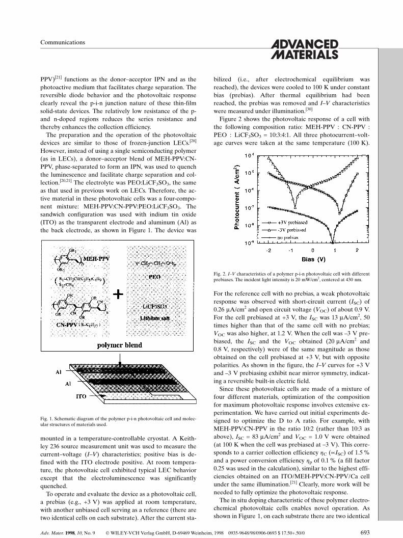
Figure 2 shows the photovoltaic response of a cell withthe following composition ratio: MEH-PPV : CN-PPV :PEO : LiCF3SO3 = 10:3:4:1. All three photocurrent±volt-age curves were taken at the same temperature (100 K).
For the reference cell with no prebias, a weak photovoltaicresponse was observed with short-circuit current (ISC) of0.26 mA/cm2 and open circuit voltage (VOC) of about 0.9 V.For the cell prebiased at +3 V, the ISC was 13 mA/cm2, 50times higher than that of the same cell with no prebias;VOC was also higher, at 1.2 V. When the cell was ±3 V pre-biased, the ISC and the VOC obtained (20 mA/cm2 and0.8 V, respectively) were of the same magnitude as thoseobtained on the cell prebiased at +3 V, but with oppositepolarities. As shown in the figure, the I±V curves for +3 Vand ±3 V prebiasing exhibit near mirror symmetry, indicat-ing a reversible built-in electric field.
Since these photovoltaic cells are made of a mixture offour different materials, optimization of the compositionfor maximum photovoltaic response involves extensive ex-perimentation. We have carried out initial experiments de-signed to optimize the D to A ratio. For example, withMEH-PPV:CN-PPV in the ratio 10:2 (rather than 10:3 asabove), ISC = 83 mA/cm2 and VOC = 1.0 V were obtained(at 100 K when the cell was prebiased at ±3 V). This corre-sponds to a carrier collection efficiency ZC (µISC) of 1.5 %and a power conversion efficiency Zp of 0.1 % (a fill factor0.25 was used in the calculation), similar to the highest effi-ciencies obtained on an ITO/MEH-PPV:CN-PPV/Ca cellunder the same illumination.[21] Clearly, more work will beneeded to fully optimize the photovoltaic response.
The in situ doping characteristic of these polymer electro-chemical photovoltaic cells enables novel operation. Asshown in Figure 1, on each substrate there are two identical
Adv. Mater. 1998, 10, No. 9 Ó WILEY-VCH Verlag GmbH, D-69469 Weinheim, 1998 0935-9648/98/0906-0693 $ 17.50+.50/0 693
Communications
Fig. 1. Schematic diagram of the polymer p-i-n photovoltaic cell and molec-ular structures of materials used.
Fig. 2. I±V characteristics of a polymer p-i-n photovoltaic cell with differentprebiases. The incident light intensity is 20 mW/cm2, centered at 430 nm.
Communications
694 Ó WILEY-VCH Verlag GmbH, D-69469 Weinheim, 1998 0935-9648/98/0906-0694 $ 17.50+.50/0 Adv. Mater. 1998, 10, No. 9
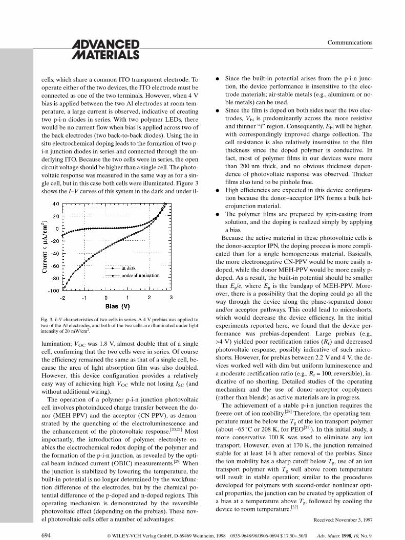
cells, which share a common ITO transparent electrode. Tooperate either of the two devices, the ITO electrode must beconnected as one of the two terminals. However, when 4 Vbias is applied between the two Al electrodes at room tem-perature, a large current is observed, indicative of creatingtwo p-i-n diodes in series. With two polymer LEDs, therewould be no current flow when bias is applied across two ofthe back electrodes (two back-to-back diodes). Using the insitu electrochemical doping leads to the formation of two p-i-n junction diodes in series and connected through the un-derlying ITO. Because the two cells were in series, the opencircuit voltage should be higher than a single cell. The photo-voltaic response was measured in the same way as for a sin-gle cell, but in this case both cells were illuminated. Figure 3shows the I±V curves of this system in the dark and under il-
lumination; VOC was 1.8 V, almost double that of a singlecell, confirming that the two cells were in series. Of coursethe efficiency remained the same as that of a single cell, be-cause the area of light absorption film was also doubled.However, this device configuration provides a relativelyeasy way of achieving high VOC while not losing ISC (andwithout additional wiring).
The operation of a polymer p-i-n junction photovoltaiccell involves photoinduced charge transfer between the do-nor (MEH-PPV) and the acceptor (CN-PPV), as demon-strated by the quenching of the electroluminescence andthe enhancement of the photovoltaic response.[20,21] Mostimportantly, the introduction of polymer electrolyte en-ables the electrochemical redox doping of the polymer andthe formation of the p-i-n junction, as revealed by the opti-cal beam induced current (OBIC) measurements.[29] Whenthe junction is stabilized by lowering the temperature, thebuilt-in potential is no longer determined by the workfunc-tion difference of the electrodes, but by the chemical po-tential difference of the p-doped and n-doped regions. Thisoperating mechanism is demonstrated by the reversiblephotovoltaic effect (depending on the prebias). These nov-el photovoltaic cells offer a number of advantages:
l Since the built-in potential arises from the p-i-n junc-tion, the device performance is insensitive to the elec-trode materials; air-stable metals (e.g., aluminum or no-ble metals) can be used.
l Since the film is doped on both sides near the two elec-trodes, Vbi is predominantly across the more resistiveand thinner ªiº region. Consequently, Ebi will be higher,with correspondingly improved charge collection. Thecell resistance is also relatively insensitive to the filmthickness since the doped polymer is conductive. Infact, most of polymer films in our devices were morethan 200 nm thick, and no obvious thickness depen-dence of photovoltaic response was observed. Thickerfilms also tend to be pinhole free.
l High efficiencies are expected in this device configura-tion because the donor±acceptor IPN forms a bulk het-erojunction material.
l The polymer films are prepared by spin-casting fromsolution, and the doping is realized simply by applyinga bias.
Because the active material in these photovoltaic cells isthe donor-acceptor IPN, the doping process is more compli-cated than for a single homogeneous material. Basically,the more electronegative CN-PPV would be more easily n-doped, while the donor MEH-PPV would be more easily p-doped. As a result, the built-in potential should be smallerthan Eg/e, where Eg is the bandgap of MEH-PPV. More-over, there is a possibility that the doping could go all theway through the device along the phase-separated donorand/or acceptor pathways. This could lead to microshorts,which would decrease the device efficiency. In the initialexperiments reported here, we found that the device per-formance was prebias-dependent. Large prebias (e.g.,>4 V) yielded poor rectification ratios (Rr) and decreasedphotovoltaic response, possibly indicative of such micro-shorts. However, for prebias between 2.2 V and 4 V, the de-vices worked well with dim but uniform luminescence anda moderate rectification ratio (e.g., Rr = 100, reversible), in-dicative of no shorting. Detailed studies of the operatingmechanism and the use of donor±acceptor copolymers(rather than blends) as active materials are in progress.
The achievement of a stable p-i-n junction requires thefreeze-out of ion mobility.[28] Therefore, the operating tem-perature must be below the Tg of the ion transport polymer(about ±65 �C or 208 K, for PEO[31]). In this initial study, amore conservative 100 K was used to eliminate any iontransport. However, even at 170 K, the junction remainedstable for at least 14 h after removal of the prebias. Sincethe ion mobility has a sharp cutoff below Tg, use of an iontransport polymer with Tg well above room temperaturewill result in stable operation; similar to the proceduresdeveloped for polymers with second-order nonlinear opti-cal properties, the junction can be created by application ofa bias at a temperature above Tg, followed by cooling thedevice to room temperature.[32]
Received: November 3, 1997
Fig. 3. I±V characteristics of two cells in series. A 4 V prebias was applied totwo of the Al electrodes, and both of the two cells are illuminated under lightintensity of 20 mW/cm2.
±[1] T. Tani, P. M. Grant, W. D. Gill, G. B. Street, T. C. Clarke, Solid State
Commun. 1980, 33, 499.[2] J. Tsukamoto, H. Ohigrashi, K. Matsumura, A. Takahashi, Synth. Met.
1982, 4, 177.[3] B. R. Weinberger, M. Akhtar, S. C. Gau, Synth. Met. 1982, 4, 187.[4] M. Cadene, M. Rolland, M. Abd Lefdil, J. Bougnot, M. J. M. Abadie,
Mol. Cryst. Liq. Cryst. 1985, 121, 297.[5] A. Usuki, M. Murase, T. Kurauchi, Synth. Met. 1987, 18, 705.[6] J. Kanicki, in Handbook of Conducting Polymers (Ed: T. A. Skot-
heim), Marcel Dekker, New York 1986.[7] H. Sasabe, T. Furuno, T. Wada, Mol. Cryst. Liq. Cryst. 1988, 160, 281.[8] S. Glenis, G. Horowitz, G. Tourillon, F. Garnier, Thin Solid Films 1984,
111, 93.[9] S. Glenis, G. Tourillon, F. Garnier, Thin Solid Films 1986, 139, 221.
[10] G. Horowitz, F. Garnier, Sol. Energy Mater. 1986, 13, 47.[11] S. Karg, W. Riess, M. Meier, M. Schwoerer, Synth. Met. 1993, 55±57,
4186.[12] R. N. Marks, J. J. M. Halls, D. D. C. Bradley, R. H. Friend, A. B.
Holmes, J. Phys.: Condens. Matter 1994, 6, 1379.[13] G. Yu, C. Zhang, A. J. Heeger, Appl. Phys. Lett. 1994, 64, 1540.[14] N. S. Sariciftci, L. Smilowitz, A. J. Heeger, F. Wudl, Science 1992, 258,
1474.[15] N. S. Sariciftci, D. Braun, C. Zhang, V. I. Srdanov, A. J. Heeger, F.
Wudl, Appl. Phys. Lett. 1993, 62, 585.[16] G. Yu, J. Gao, J. C. Hummelen, F. Wudl, A. J. Heeger, Science 1995,
270, 1789.
[17] J. Gao, H. Wang, F. Hide, Synth. Met. 1997, 84, 979.[18] S. C. Veenstra, G. G. Malliaras, H. J. Brouwer, F. J. Esselink, V. V.
Krasnikov, P. F. van Hutten, J. Wildeman, H. T. Jonkman, G. A. Sa-watzky, G. Hadziioannou, Synth. Met. 1997, 84, 973.
[19] K. Yoshino, K. Tada, A. Fujii, E. M. Conwell, A. A. Zakhidov, IEEETrans. Electron Dev. 1997, 44, 1315.
[20] J. J. M. Halls, C. A. Walsh, N. C. Greenham, E. A. Marseglia, R. H.Friend, S. C. Moratti, A. B. Holmes, Nature 1995, 376, 498.
[21] G. Yu, A. J. Heeger, J. Appl. Phys. 1995, 78, 4510.[22] Q. Pei, G. Yu, C. Zhang, Y. Yang, A. J. Heeger, Science 1995, 269,
1086.[23] Q. Pei, Y. Yang, G. Yu, C. Zhang, A. J. Heeger, J. Am. Chem. Soc.
1996, 118, 3922.[24] Y. Cao, G. Yu, C. Y. Yang, A. J. Heeger, Appl. Phys. Lett. 1996, 68, 3218.[25] Y. Yang, Q. Pei, J. Appl. Phys. 1996, 68, 2708.[26] D. L. Smith, J. Appl. Phys. 1997, 81, 2869.[27] I. Riess, D. Cohen, J. Appl. Phys., 1997, 82, 3147.[28] J. Gao, G. Yu, A. J. Heeger, Appl. Phys. Lett. 1997, 71, 1293.[29] D. J. Dick, A. J. Heeger, Y. Yang, Q. Pei, Adv. Mater. 1996, 8, 985.[30] The illumination is filtered light from a tungsten lamp, centered at
430 nm and with an intensity of 20 mW/cm2.[31] M. D. Glass, in Electrochemical Science and Technology of Polymers
(Ed: R. G. Linford), Elsevier Applied Science, London 1987.[32] G. Yu, Y. Cao, M. Andersson, J. Gao, A. J. Heeger, Adv. Mater. 1998,
10, 385.
Adv. Mater. 1998, 10, No. 9 Ó WILEY-VCH Verlag GmbH, D-69469 Weinheim, 1998 0935-9648/98/0906-0695 $ 17.50+.50/0 695
Communications
_______________________