Embed Size (px)
Citation preview

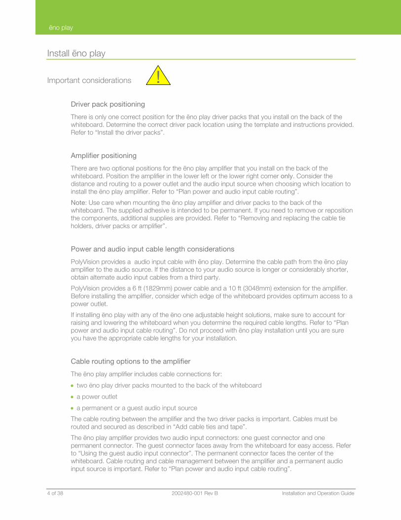

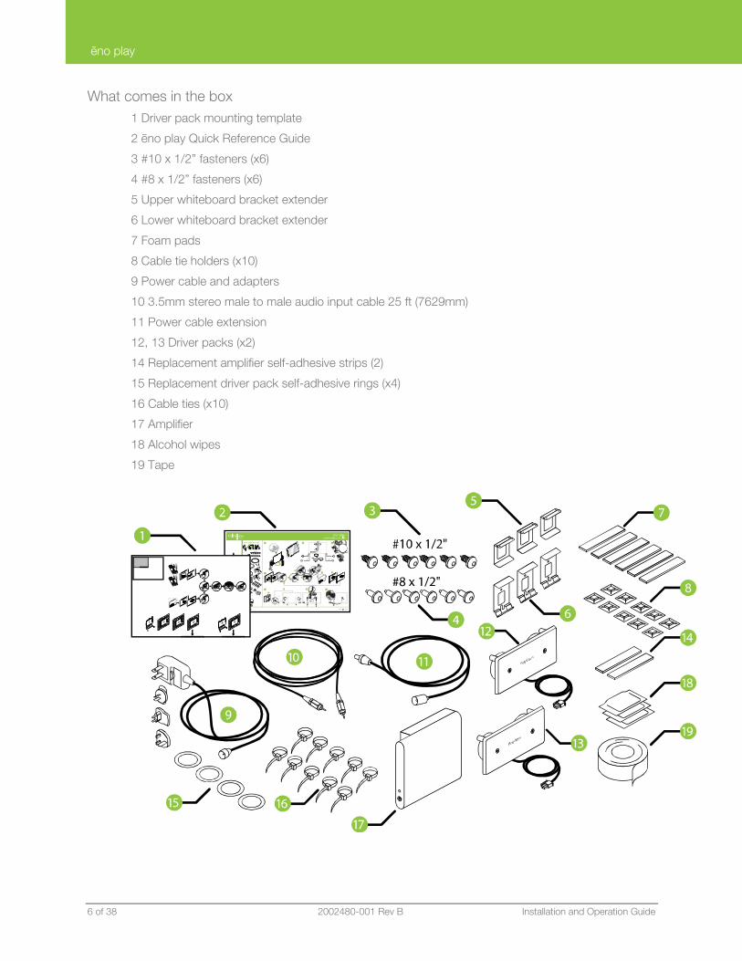
ēno play
PolyVision 2002480-001 Rev B 7 of 38
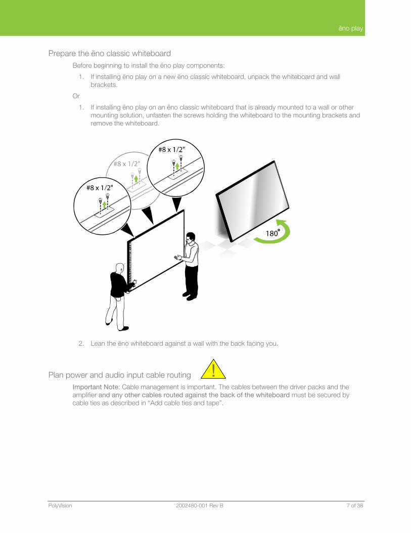
Prepare the ēno classic whiteboard Before beginning to install the ēno play components:
1. If installing ēno play on a new ēno classic whiteboard, unpack the whiteboard and wall brackets.
Or
1. If installing ēno play on an ēno classic whiteboard that is already mounted to a wall or other mounting solution, unfasten the screws holding the whiteboard to the mounting brackets and remove the whiteboard.
2. Lean the ēno whiteboard against a wall with the back facing you.
Plan power and audio input cable routing Important Note: Cable management is important. The cables between the driver packs and the amplifier and any other cables routed against the back of the whiteboard must be secured by cable ties as described in “Add cable ties and tape”.
!
ēno play
8 of 38 2002480-001 Rev B Installation and Operation Guide
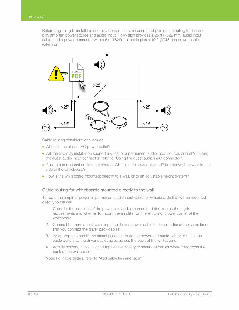
Before beginning to install the ēno play components, measure and plan cable routing for the ēno play amplifier power source and audio input. PolyVision provides a 25 ft (7629 mm) audio input cable, and a power connector with a 6 ft (1829mm) cable plus a 10 ft (3048mm) power cable extension.
Cable routing considerations include:
• Where is the closest AC power outlet?
• Will the ēno play installation support a guest or a permanent audio input source, or both? If using the guest audio input connector, refer to “Using the guest audio input connector”.
• If using a permanent audio input source, Where is the source located? Is it above, below or to one side of the whiteboard?
• How is the whiteboard mounted: directly to a wall, or to an adjustable height system?
Cable routing for whiteboards mounted directly to the wall
To route the amplifier power or permanent audio input cable for whiteboards that will be mounted directly to the wall:
1. Consider the locations of the power and audio sources to determine cable length requirements and whether to mount the amplifier on the left or right lower corner of the whiteboard.
2. Connect the permanent audio input cable and power cable to the amplifier at the same time that you connect the driver pack cables.
3. As appropriate and to the extent possible, route the power and audio cables in the same cable bundle as the driver pack cables across the back of the whiteboard.
4. Add tie holders, cable ties and tape as necessary to secure all cables where they cross the back of the whiteboard.
Note: For more details, refer to “Add cable ties and tape”.
ēno play
PolyVision 2002480-001 Rev B 9 of 38
Cable routing for adjustable height mobile stand or wall mount options
Note: When installing ēno play on a whiteboard that will be mounted using an adjustable height system, do not connect the power or permanent audio input cable to the amplifier until after cable routing is complete.
The adjustable height mobile stand and adjustable height wall mount provide a variety of cable routing options for the power and permanent audio input cable, including:
• routing cables to sources above the whiteboard through the lift system turret within a split corrugated conduit that is provided with the mounting solution
• routing cables from sources below the whiteboard
• for the adjustable height mobile stand, routing the audio input cable from a laptop tray fastened to the back of the lift system
For more cable routing details relating to these options, refer to the installation and operation manuals for your whiteboard mounting solution.
To route the amplifier power or permanent audio input cable when the whiteboard is mounted to an adjustable height system:
1. Consider the locations of the power and audio sources to determine cable length requirements, routing options, and whether to mount the amplifier on the lower left or lower right corner of the whiteboard.
2. If the source is located above the whiteboard, route the cable down through the lift system turret. Then route the cable from the turret base to the amplifier by passing the cable between the lift system tubular structure and the whiteboard.
3. If the source is located below the whiteboard, route the cable from the source to the amplifier by passing the cable between the lift system tubular structure and the whiteboard.
4. Add a cable tie to the base of the lift system, assuring a service loop between the cable tie and the amplifier:
• ēno 2610 requires 27” (685mm) audio and power service loop
• ēno 2810 requires 35” (889mm) audio and power service loop
Note: For details, refer to “Option: Cable management for adjustable height systems”.
ēno play
10 of 38 2002480-001 Rev B Installation and Operation Guide
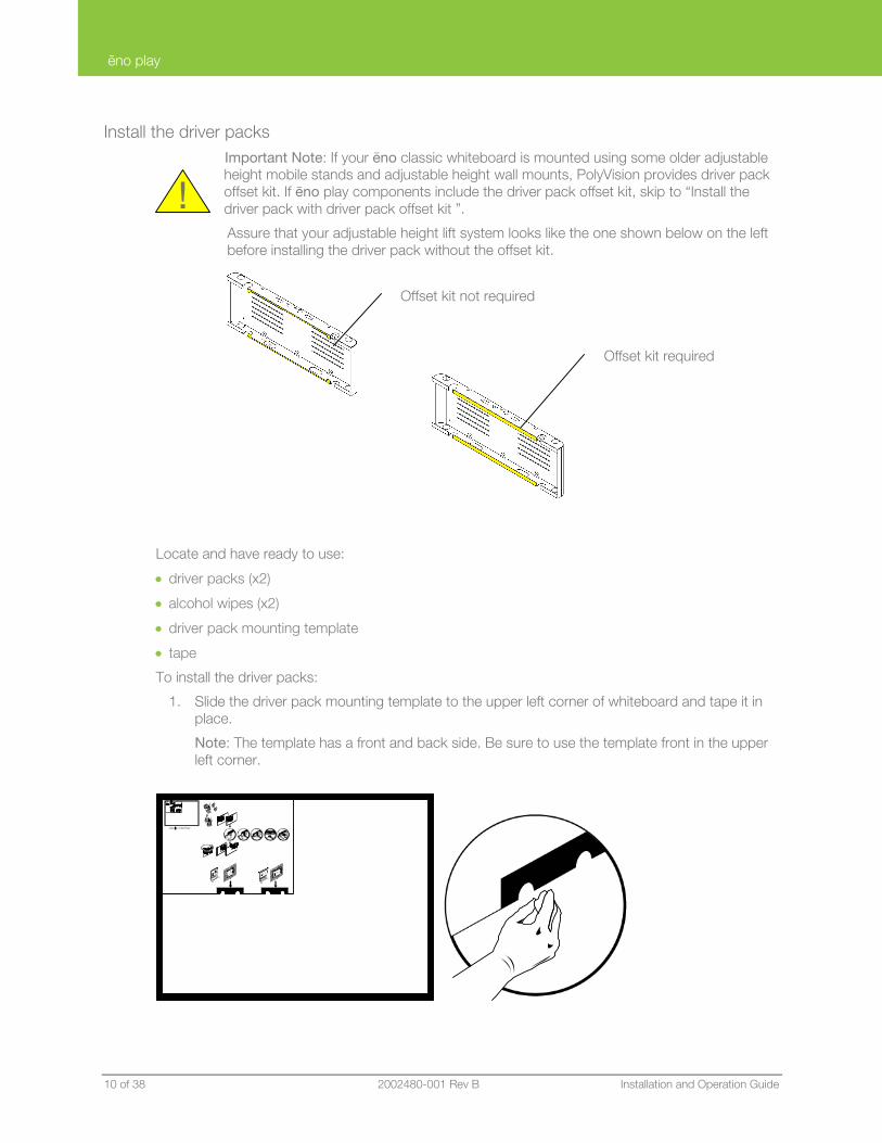
Install the driver packs Important Note: If your ēno classic whiteboard is mounted using some older adjustable height mobile stands and adjustable height wall mounts, PolyVision provides driver pack offset kit. If ēno play components include the driver pack offset kit, skip to “Install the driver pack with driver pack offset kit ”.
Assure that your adjustable height lift system looks like the one shown below on the left before installing the driver pack without the offset kit.
Locate and have ready to use:
• driver packs (x2)
• alcohol wipes (x2)
• driver pack mounting template
• tape
To install the driver packs:
1. Slide the driver pack mounting template to the upper left corner of whiteboard and tape it in place.
Note: The template has a front and back side. Be sure to use the template front in the upper left corner.
!
Offset kit required
Offset kit not required
ēno play
PolyVision 2002480-001 Rev B 11 of 38
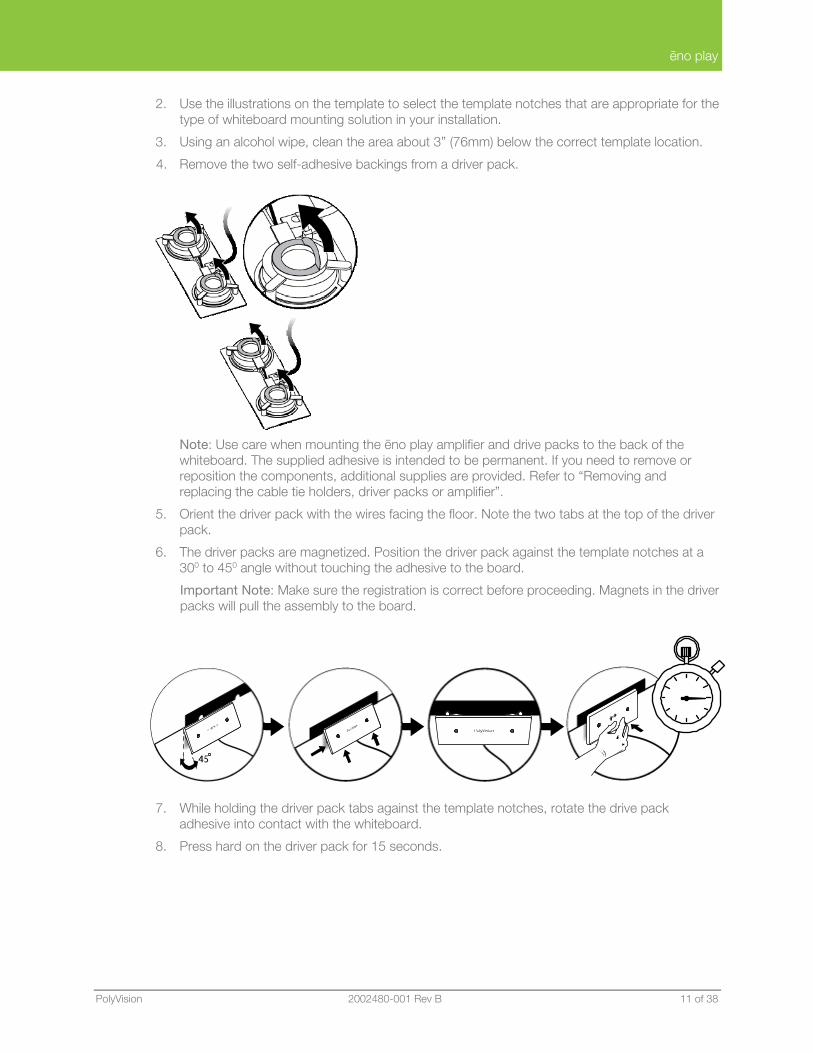
2. Use the illustrations on the template to select the template notches that are appropriate for the type of whiteboard mounting solution in your installation.
3. Using an alcohol wipe, clean the area about 3” (76mm) below the correct template location.
4. Remove the two self-adhesive backings from a driver pack.
Note: Use care when mounting the ēno play amplifier and drive packs to the back of the whiteboard. The supplied adhesive is intended to be permanent. If you need to remove or reposition the components, additional supplies are provided. Refer to “Removing and replacing the cable tie holders, driver packs or amplifier”.
5. Orient the driver pack with the wires facing the floor. Note the two tabs at the top of the driver pack.
6. The driver packs are magnetized. Position the driver pack against the template notches at a 300 to 450 angle without touching the adhesive to the board.
Important Note: Make sure the registration is correct before proceeding. Magnets in the driver packs will pull the assembly to the board.
7. While holding the driver pack tabs against the template notches, rotate the drive pack adhesive into contact with the whiteboard.
8. Press hard on the driver pack for 15 seconds.
ēno play
12 of 38 2002480-001 Rev B Installation and Operation Guide
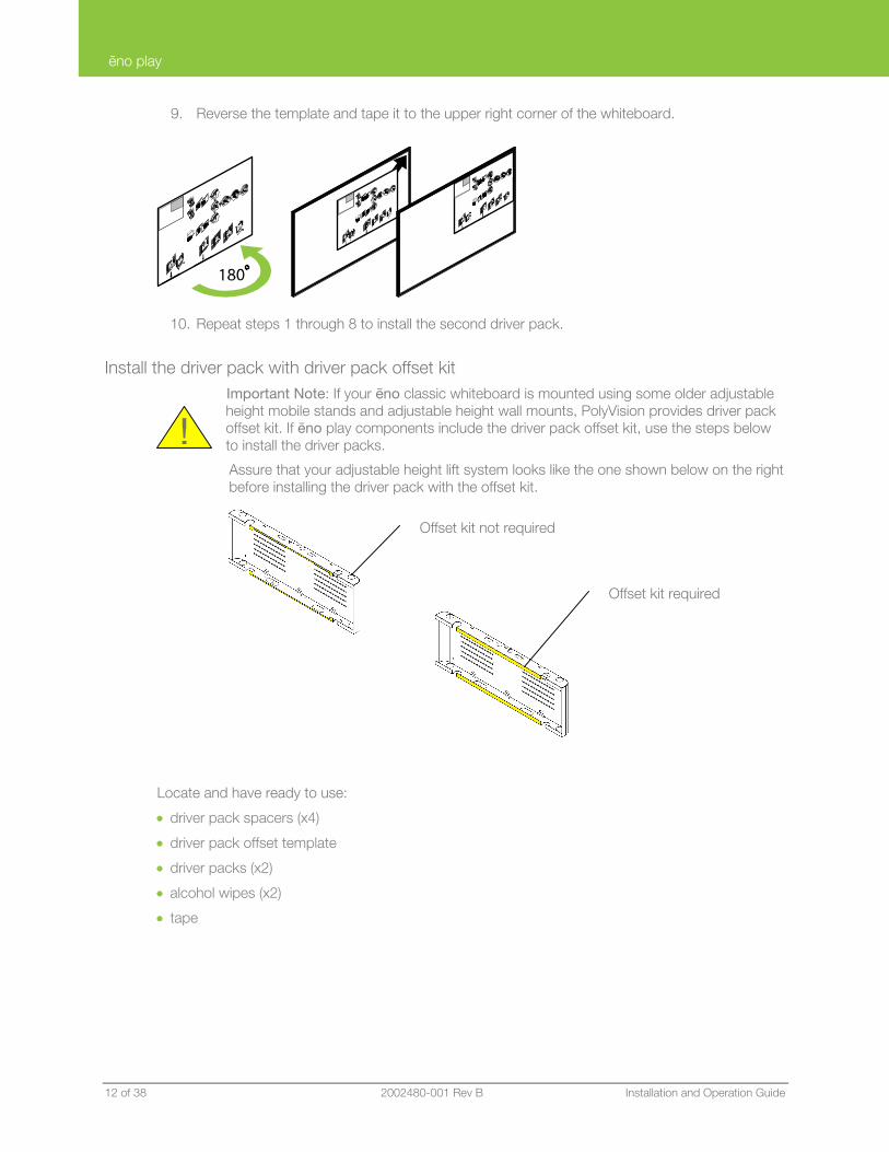
9. Reverse the template and tape it to the upper right corner of the whiteboard.
10. Repeat steps 1 through 8 to install the second driver pack.
Install the driver pack with driver pack offset kit Important Note: If your ēno classic whiteboard is mounted using some older adjustable height mobile stands and adjustable height wall mounts, PolyVision provides driver pack offset kit. If ēno play components include the driver pack offset kit, use the steps below to install the driver packs.
Assure that your adjustable height lift system looks like the one shown below on the right before installing the driver pack with the offset kit.
Locate and have ready to use:
• driver pack spacers (x4)
• driver pack offset template
• driver packs (x2)
• alcohol wipes (x2)
• tape
!
Offset kit required
Offset kit not required
ēno play
PolyVision 2002480-001 Rev B 13 of 38
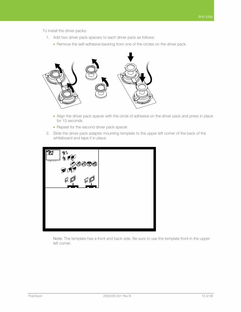
To install the driver packs:
1. Add two driver pack spacers to each driver pack as follows:
• Remove the self-adhesive backing from one of the circles on the driver pack.
• Align the driver pack spacer with the circle of adhesive on the driver pack and press in place for 15 seconds.
• Repeat for the second driver pack spacer.
2. Slide the driver pack adapter mounting template to the upper left corner of the back of the whiteboard and tape it in place.
Note: The template has a front and back side. Be sure to use the template front in the upper left corner.
ēno play
14 of 38 2002480-001 Rev B Installation and Operation Guide
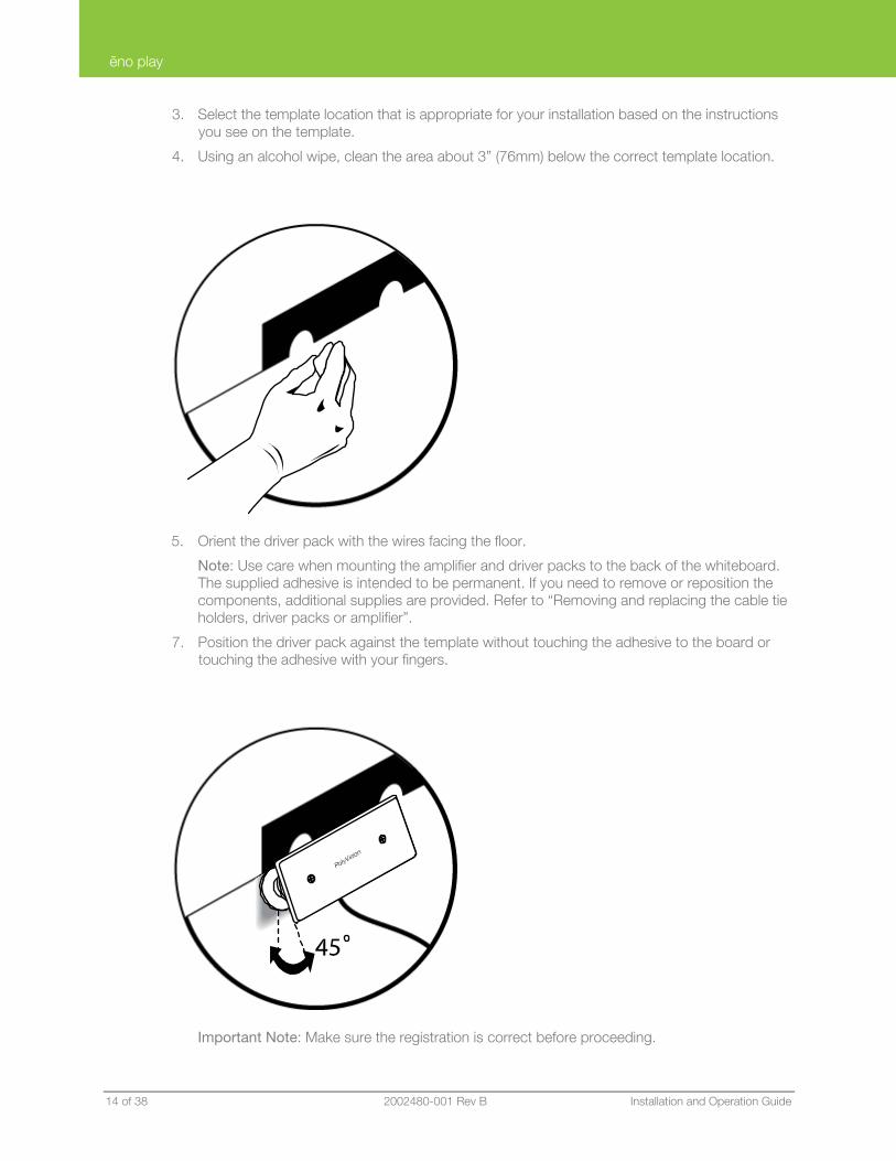
3. Select the template location that is appropriate for your installation based on the instructions you see on the template.
4. Using an alcohol wipe, clean the area about 3” (76mm) below the correct template location.
5. Orient the driver pack with the wires facing the floor.
Note: Use care when mounting the amplifier and driver packs to the back of the whiteboard. The supplied adhesive is intended to be permanent. If you need to remove or reposition the components, additional supplies are provided. Refer to “Removing and replacing the cable tie holders, driver packs or amplifier”.
7. Position the driver pack against the template without touching the adhesive to the board or touching the adhesive with your fingers.
Important Note: Make sure the registration is correct before proceeding.
ēno play
PolyVision 2002480-001 Rev B 15 of 38
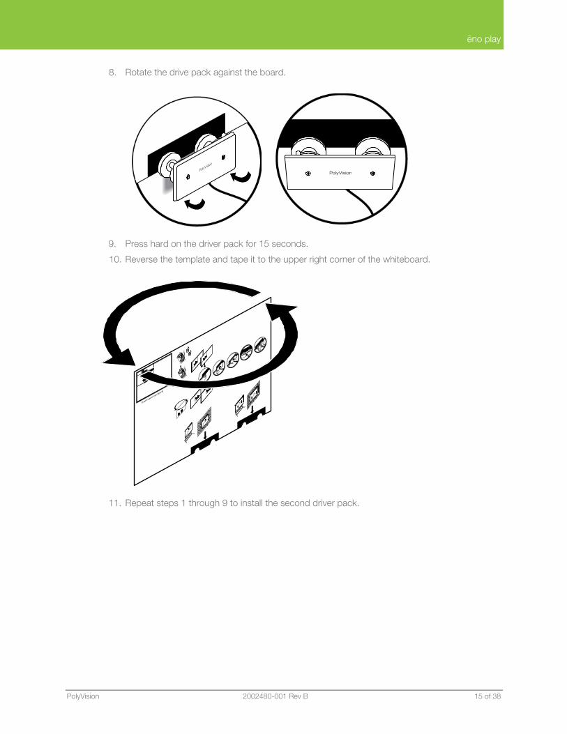
8. Rotate the drive pack against the board.
9. Press hard on the driver pack for 15 seconds.
10. Reverse the template and tape it to the upper right corner of the whiteboard.
11. Repeat steps 1 through 9 to install the second driver pack.
ēno play
16 of 38 2002480-001 Rev B Installation and Operation Guide
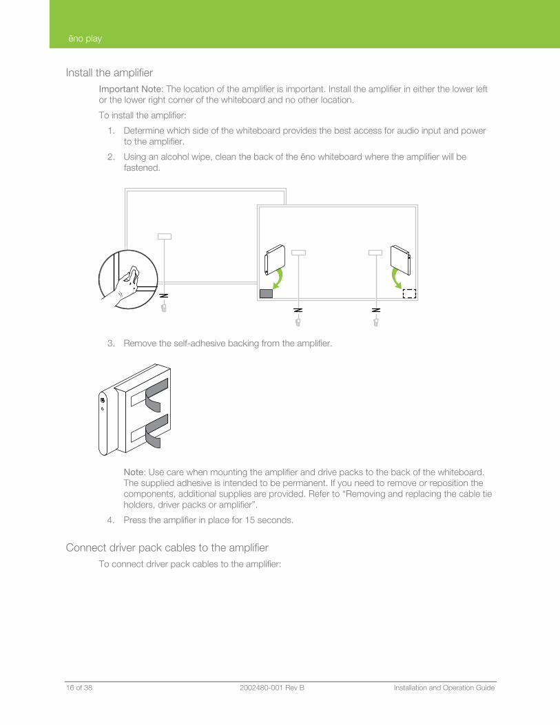
Install the amplifier Important Note: The location of the amplifier is important. Install the amplifier in either the lower left or the lower right corner of the whiteboard and no other location.
To install the amplifier:
1. Determine which side of the whiteboard provides the best access for audio input and power to the amplifier.
2. Using an alcohol wipe, clean the back of the ēno whiteboard where the amplifier will be fastened.
3. Remove the self-adhesive backing from the amplifier.
Note: Use care when mounting the amplifier and drive packs to the back of the whiteboard. The supplied adhesive is intended to be permanent. If you need to remove or reposition the components, additional supplies are provided. Refer to “Removing and replacing the cable tie holders, driver packs or amplifier”.
4. Press the amplifier in place for 15 seconds.
Connect driver pack cables to the amplifier To connect driver pack cables to the amplifier:
ēno play
PolyVision 2002480-001 Rev B 17 of 38
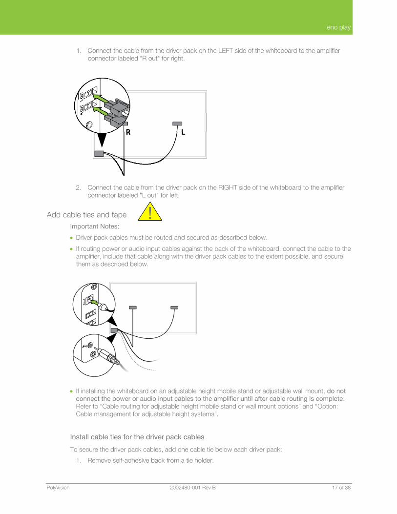
1. Connect the cable from the driver pack on the LEFT side of the whiteboard to the amplifier connector labeled "R out" for right.
2. Connect the cable from the driver pack on the RIGHT side of the whiteboard to the amplifier connector labeled "L out" for left.
Add cable ties and tape Important Notes:
• Driver pack cables must be routed and secured as described below.
• If routing power or audio input cables against the back of the whiteboard, connect the cable to the amplifier, include that cable along with the driver pack cables to the extent possible, and secure them as described below.
• If installing the whiteboard on an adjustable height mobile stand or adjustable wall mount, do not connect the power or audio input cables to the amplifier until after cable routing is complete. Refer to “Cable routing for adjustable height mobile stand or wall mount options” and “Option: Cable management for adjustable height systems”.
Install cable ties for the driver pack cables
To secure the driver pack cables, add one cable tie below each driver pack:
1. Remove self-adhesive back from a tie holder.
!
ēno play
18 of 38 2002480-001 Rev B Installation and Operation Guide
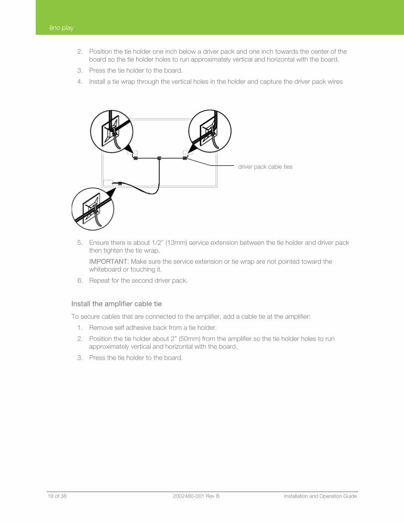
2. Position the tie holder one inch below a driver pack and one inch towards the center of the board so the tie holder holes to run approximately vertical and horizontal with the board.
3. Press the tie holder to the board.
4. Install a tie wrap through the vertical holes in the holder and capture the driver pack wires
5. Ensure there is about 1/2” (13mm) service extension between the tie holder and driver pack then tighten the tie wrap.
IMPORTANT: Make sure the service extension or tie wrap are not pointed toward the whiteboard or touching it.
6. Repeat for the second driver pack.
Install the amplifier cable tie
To secure cables that are connected to the amplifier, add a cable tie at the amplifier:
1. Remove self adhesive back from a tie holder.
2. Position the tie holder about 2” (50mm) from the amplifier so the tie holder holes to run approximately vertical and horizontal with the board.
3. Press the tie holder to the board.
driver pack cable ties
ēno play
PolyVision 2002480-001 Rev B 19 of 38
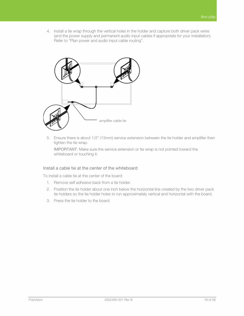
4. Install a tie wrap through the vertical holes in the holder and capture both driver pack wires (and the power supply and permanent audio input cables if appropriate for your installation). Refer to “Plan power and audio input cable routing”.
5. Ensure there is about 1/2” (13mm) service extension between the tie holder and amplifier then tighten the tie wrap.
IMPORTANT: Make sure the service extension or tie wrap is not pointed toward the whiteboard or touching it.
Install a cable tie at the center of the whiteboard
To install a cable tie at the center of the board:
1. Remove self adhesive back from a tie holder.
2. Position the tie holder about one inch below the horizontal line created by the two driver pack tie holders so the tie holder holes to run approximately vertical and horizontal with the board.
3. Press the tie holder to the board.
amplifier cable tie
ēno play
20 of 38 2002480-001 Rev B Installation and Operation Guide
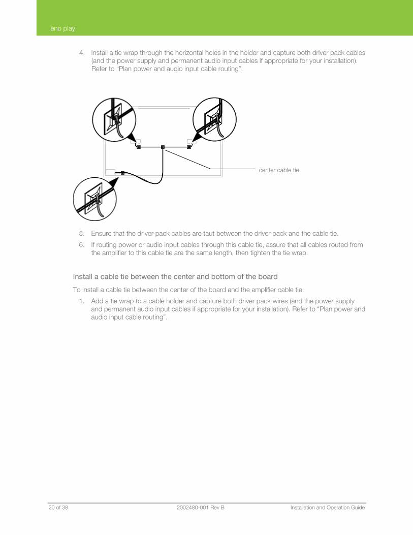
4. Install a tie wrap through the horizontal holes in the holder and capture both driver pack cables (and the power supply and permanent audio input cables if appropriate for your installation). Refer to “Plan power and audio input cable routing”.
5. Ensure that the driver pack cables are taut between the driver pack and the cable tie.
6. If routing power or audio input cables through this cable tie, assure that all cables routed from the amplifier to this cable tie are the same length, then tighten the tie wrap.
Install a cable tie between the center and bottom of the board
To install a cable tie between the center of the board and the amplifier cable tie:
1. Add a tie wrap to a cable holder and capture both driver pack wires (and the power supply and permanent audio input cables if appropriate for your installation). Refer to “Plan power and audio input cable routing”.
center cable tie
ēno play
PolyVision 2002480-001 Rev B 21 of 38
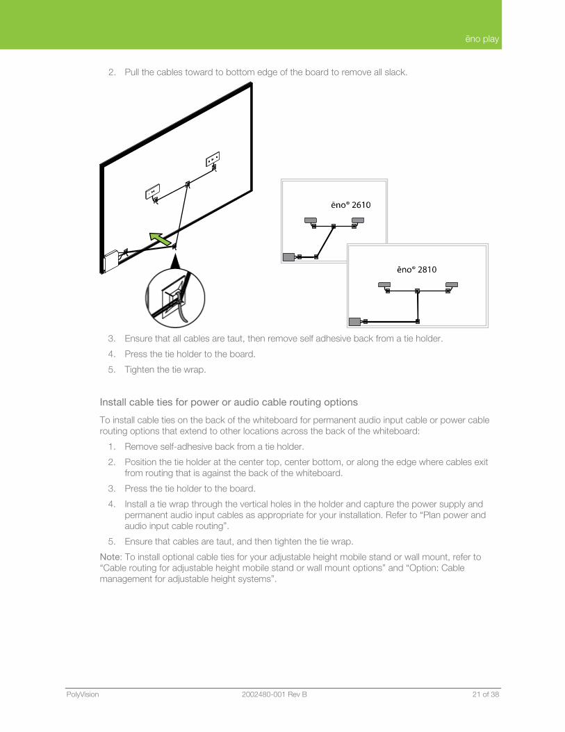
2. Pull the cables toward to bottom edge of the board to remove all slack.
3. Ensure that all cables are taut, then remove self adhesive back from a tie holder.
4. Press the tie holder to the board.
5. Tighten the tie wrap.
Install cable ties for power or audio cable routing options
To install cable ties on the back of the whiteboard for permanent audio input cable or power cable routing options that extend to other locations across the back of the whiteboard:
1. Remove self-adhesive back from a tie holder.
2. Position the tie holder at the center top, center bottom, or along the edge where cables exit from routing that is against the back of the whiteboard.
3. Press the tie holder to the board.
4. Install a tie wrap through the vertical holes in the holder and capture the power supply and permanent audio input cables as appropriate for your installation. Refer to “Plan power and audio input cable routing”.
5. Ensure that cables are taut, and then tighten the tie wrap.
Note: To install optional cable ties for your adjustable height mobile stand or wall mount, refer to “Cable routing for adjustable height mobile stand or wall mount options” and “Option: Cable management for adjustable height systems”.
ēno play
22 of 38 2002480-001 Rev B Installation and Operation Guide
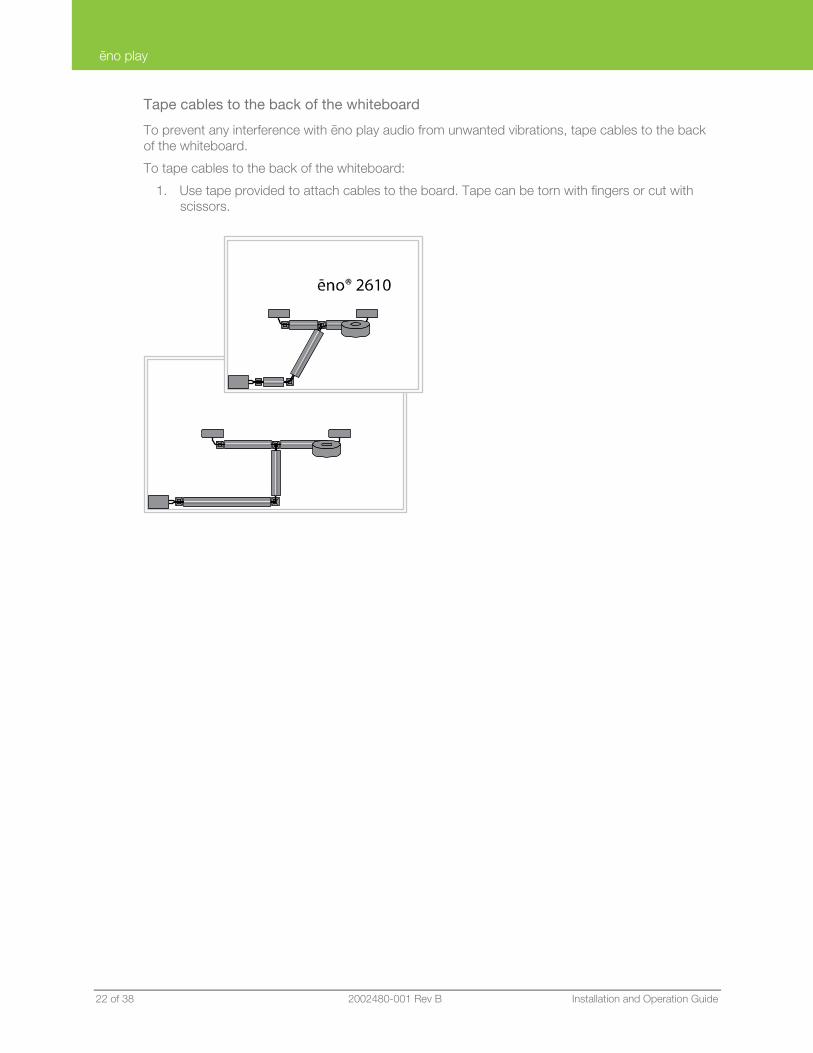
Tape cables to the back of the whiteboard
To prevent any interference with ēno play audio from unwanted vibrations, tape cables to the back of the whiteboard.
To tape cables to the back of the whiteboard:
1. Use tape provided to attach cables to the board. Tape can be torn with fingers or cut with scissors.
ēno play
PolyVision 2002480-001 Rev B 23 of 38
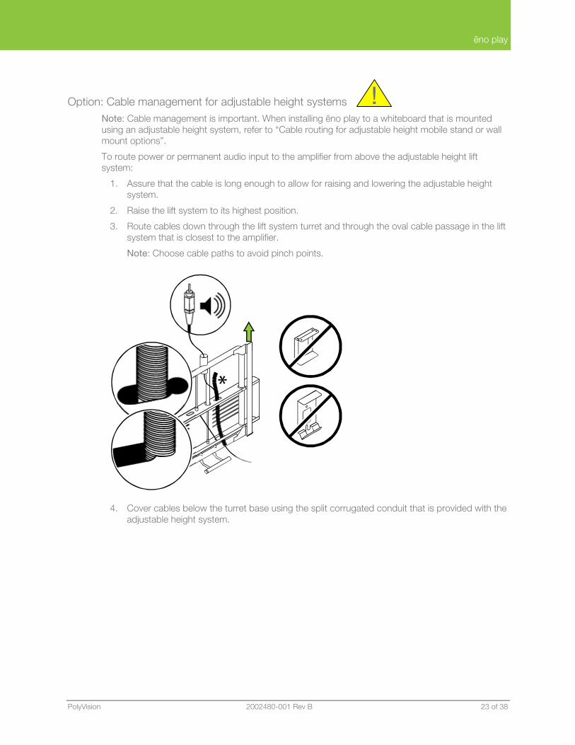
Option: Cable management for adjustable height systems Note: Cable management is important. When installing ēno play to a whiteboard that is mounted using an adjustable height system, refer to “Cable routing for adjustable height mobile stand or wall mount options”.
To route power or permanent audio input to the amplifier from above the adjustable height lift system:
1. Assure that the cable is long enough to allow for raising and lowering the adjustable height system.
2. Raise the lift system to its highest position.
3. Route cables down through the lift system turret and through the oval cable passage in the lift system that is closest to the amplifier.
Note: Choose cable paths to avoid pinch points.
4. Cover cables below the turret base using the split corrugated conduit that is provided with the adjustable height system.
!
ēno play
24 of 38 2002480-001 Rev B Installation and Operation Guide
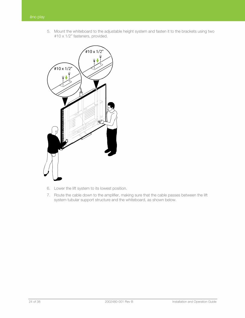
5. Mount the whiteboard to the adjustable height system and fasten it to the brackets using two #10 x 1/2” fasteners, provided.
6. Lower the lift system to its lowest position.
7. Route the cable down to the amplifier, making sure that the cable passes between the lift system tubular support structure and the whiteboard, as shown below.
ēno play
PolyVision 2002480-001 Rev B 25 of 38
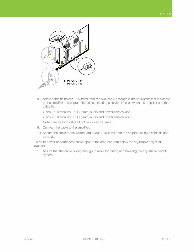
8. Add a cable tie holder 2” (50mm) from the oval cable passage in the lift system that is closest to the amplifier and capture the cable, ensuring a service loop between the amplifier and the cable tie:
• ēno 2610 requires 27” (685mm) audio and power service loop
• ēno 2810 requires 35” (889mm) audio and power service loop
Note: Service loops should not be in view of users.
9. Connect the cable to the amplifier.
10. Secure the cable to the whiteboard about 2” (50mm) from the amplifier using a cable tie and tie holder.
To route power or permanent audio input to the amplifier from below the adjustable height lift system:
1. Assure that the cable is long enough to allow for raising and lowering the adjustable height system.
ēno play
26 of 38 2002480-001 Rev B Installation and Operation Guide
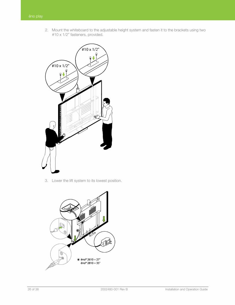
2. Mount the whiteboard to the adjustable height system and fasten it to the brackets using two #10 x 1/2” fasteners, provided.
3. Lower the lift system to its lowest position.
ēno play
PolyVision 2002480-001 Rev B 27 of 38
4. Route the cable to the amplifier, making sure that the cable passes between the lift system tubular support structure and the whiteboard, as shown above.
5. Add a cable tie holder 2” (50mm) from the oval cable passage in the lift system that is closest to the amplifier and capture the cable, ensuring a service loop between the amplifier and the cable tie:
• ēno 2610 requires 27” (685mm) audio and power service loop
• ēno 2810 requires 35” (889mm) audio and power service loop
Note: Service loops should not be in view of users.
6. Connect the cable to the amplifier.
7. Secure the cable to the whiteboard about 2” (50mm) from the amplifier using a cable tie and tie holder.
Option: Install whiteboard wall bracket extenders for fixed wall mounts Important Note: Do not install the wall bracket extenders if the whiteboard mounts to an adjustable height mobile stand or adjustable height wall mount.
!
ēno play
28 of 38 2002480-001 Rev B Installation and Operation Guide
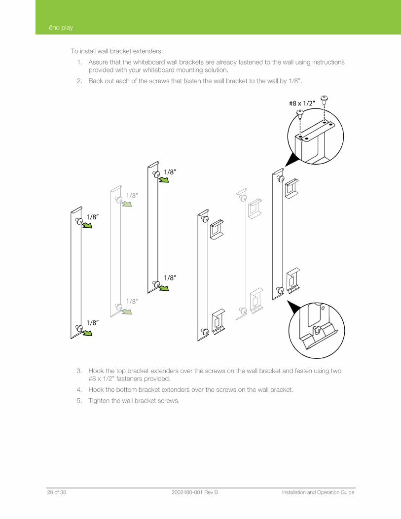
To install wall bracket extenders:
1. Assure that the whiteboard wall brackets are already fastened to the wall using instructions provided with your whiteboard mounting solution.
2. Back out each of the screws that fasten the wall bracket to the wall by 1/8”.
3. Hook the top bracket extenders over the screws on the wall bracket and fasten using two #8 x 1/2” fasteners provided.
4. Hook the bottom bracket extenders over the screws on the wall bracket.
5. Tighten the wall bracket screws.
ēno play
PolyVision 2002480-001 Rev B 29 of 38
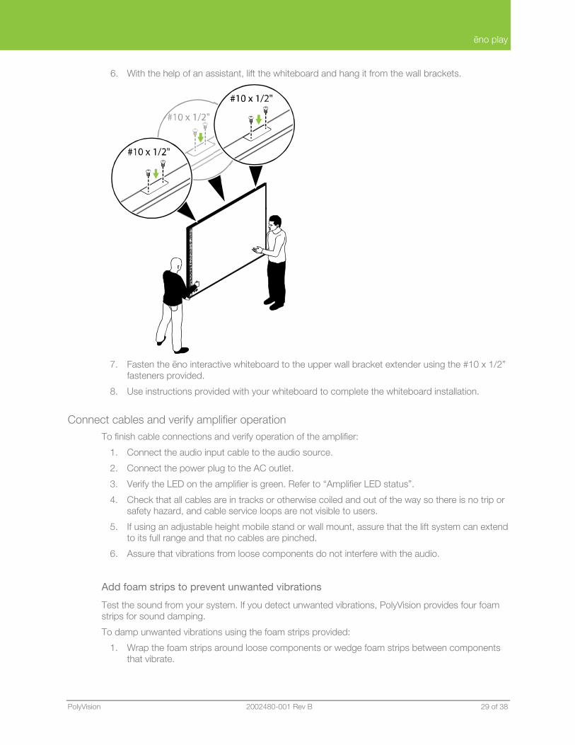
6. With the help of an assistant, lift the whiteboard and hang it from the wall brackets.
7. Fasten the ēno interactive whiteboard to the upper wall bracket extender using the #10 x 1/2”
fasteners provided.
8. Use instructions provided with your whiteboard to complete the whiteboard installation.
Connect cables and verify amplifier operation To finish cable connections and verify operation of the amplifier:
1. Connect the audio input cable to the audio source.
2. Connect the power plug to the AC outlet.
3. Verify the LED on the amplifier is green. Refer to “Amplifier LED status”.
4. Check that all cables are in tracks or otherwise coiled and out of the way so there is no trip or safety hazard, and cable service loops are not visible to users.
5. If using an adjustable height mobile stand or wall mount, assure that the lift system can extend to its full range and that no cables are pinched.
6. Assure that vibrations from loose components do not interfere with the audio.
Add foam strips to prevent unwanted vibrations
Test the sound from your system. If you detect unwanted vibrations, PolyVision provides four foam strips for sound damping.
To damp unwanted vibrations using the foam strips provided:
1. Wrap the foam strips around loose components or wedge foam strips between components that vibrate.
ēno play
30 of 38 2002480-001 Rev B Installation and Operation Guide
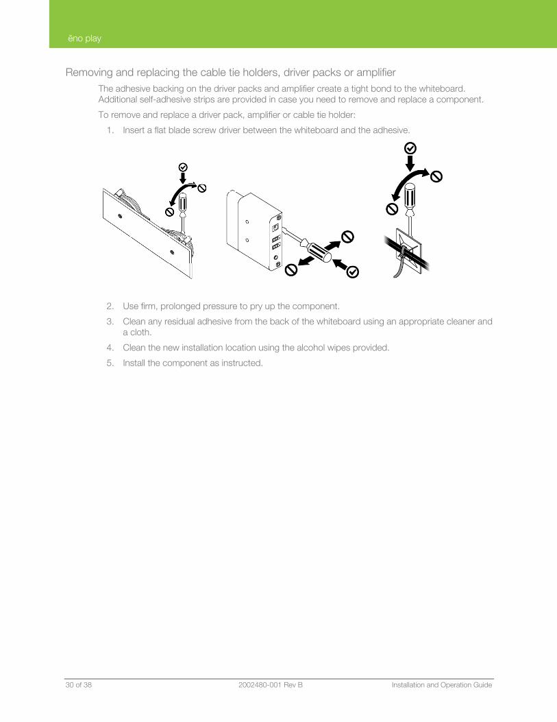
Removing and replacing the cable tie holders, driver packs or amplifier The adhesive backing on the driver packs and amplifier create a tight bond to the whiteboard. Additional self-adhesive strips are provided in case you need to remove and replace a component.
To remove and replace a driver pack, amplifier or cable tie holder:
1. Insert a flat blade screw driver between the whiteboard and the adhesive.
2. Use firm, prolonged pressure to pry up the component.
3. Clean any residual adhesive from the back of the whiteboard using an appropriate cleaner and a cloth.
4. Clean the new installation location using the alcohol wipes provided.
5. Install the component as instructed.
ēno play
PolyVision 2002480-001 Rev B 31 of 38
Install the PolyVision driver
NOTE: Install the PolyVision driver version 2.2.2 or higher to control ēno play audio from the whiteboard.
System requirements Your Windows-based computer must have:
• 500 MHz Pentium processor
• 512 MB Ram
• Windows XP SP2, Tablet XP SP2, Vista, or Windows 7
• VGA HD-15 video port
• USB port
Your Macintosh computer must have:
• PowerBook, G4, iBook, or iMac
• PowerPC G3 or higher or Intel-based processor
• 512 MB Ram
• OS X 10.4 or higher
• USB port
Your Linux system must have:
• Ubuntu 9.10 or Fedora 11 or later
• 600 MB free disk space
• 512 MB Ram
• USB port
PolyVision driver installation To install the PolyVision driver in Windows:
1. Insert the PolyVision Getting Started CD in your computer.
2. Double-click “My Computer” on your desktop.
3. Double-click the disk named “ēno® one.”
4. Double-click the Windows folder to open it.
5. Double-click “Setup.” Installation begins.
To install the PolyVision driver in Linux:
1. Insert the PolyVision Getting Started CD in your computer.
2. Double-click “My Computer” on your desktop.
3. Double-click the disk named “ēno® one.”
4. Double-click the Linux folder to open it.
5. Right-click “Setup” and choose “Properties.”
6. On the “Permissions” tab, click the “Allow executing file as program” check box.
7. Click “Close.”

ēno play
32 of 38 2002480-001 Rev B Installation and Operation Guide
8. Double-click “Setup.” Installation begins.
9. Follow the prompts you see on the screen to complete the installation.
To install the PolyVision driver on a Macintosh:
1. Insert the PolyVision Getting Started CD in your computer.
2. Double-click “My Computer” on your desktop.
3. Double-click the disk Macintosh folder to open it.
5. Double-click “Setup.” Installation begins.
6. Follow the prompts you see on the screen to complete the installation.
ēno play
PolyVision 2002480-001 Rev B 33 of 38
Operating ēno play
ēno play amplifies audio from sources including:
• the computer with the PolyVision driver installed that controls the ēno interactive whiteboard
• audio devices (ipod, CD, etc.)
• multimedia devices (DVD, VHS, etc.)
Audio and multimedia devices should normally be connected to the computer, but can also be connected directly to the ēno play amplifier.
Software options PolyVision driver (version 2.2.2 or higher) enables the ēno interactive whiteboard computer to pass microphone input directly to ēno play, bypassing the need to use the input device’s software.
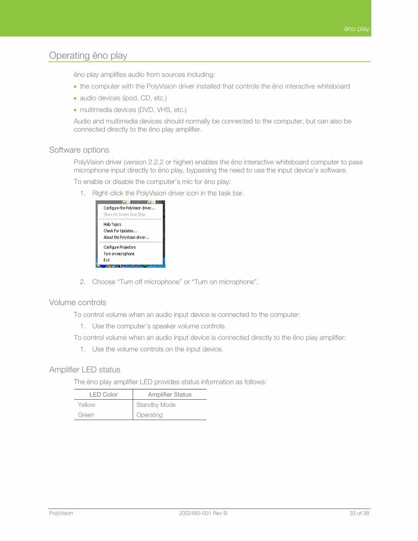
To enable or disable the computer’s mic for ēno play:
1. Right-click the PolyVision driver icon in the task bar.
2. Choose “Turn off microphone” or “Turn on microphone”.
Volume controls To control volume when an audio input device is connected to the computer:
1. Use the computer’s speaker volume controls.
To control volume when an audio input device is connected directly to the ēno play amplifier:
1. Use the volume controls on the input device.
Amplifier LED status The ēno play amplifier LED provides status information as follows:
LED Color Amplifier Status
Yellow
Green
Standby Mode
Operating
ēno play
34 of 38 2002480-001 Rev B Installation and Operation Guide
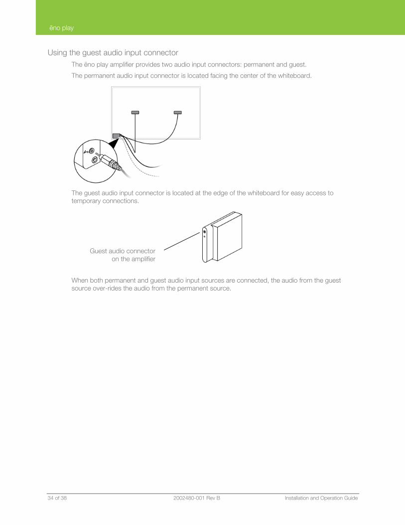
Using the guest audio input connector The ēno play amplifier provides two audio input connectors: permanent and guest.
The permanent audio input connector is located facing the center of the whiteboard.
The guest audio input connector is located at the edge of the whiteboard for easy access to temporary connections.
When both permanent and guest audio input sources are connected, the audio from the guest source over-rides the audio from the permanent source.
Guest audio connectoron the amplifier
ēno play
PolyVision 2002480-001 Rev B 35 of 38
Warranty
What Is Covered
PolyVision Corporation warrants to the original consumer or other end-user purchaser that this product is free from defects in material and workmanship for a period of five years from the date of purchase.
During the warranty period, and upon proof of purchase, the product will be repaired or replaced (with the same or similar model) at PolyVision’s option, without charge for either parts or repair labor. Shipping costs will apply. Please keep your original sales receipt or delivery invoice for proof of purchase. Without proof of the purchase date, your warranty will be defined as beginning on the date of manufacture, which is recorded by serial number at the factory. This warranty applies only to the first end-user purchaser and only when the product is used in a country for which it is labeled for sale. Some factory-reconditioned parts may be used in the assembly of this product.
What Is Not Covered
1. Any product that is sold or used outside of North America and Europe unless the product was specifically labeled for sale in that country.
2. Any product on which the serial number has been defaced, modified, or removed.
3. Damage, deterioration, or malfunction resulting from, but not limited to:
• Accident, misuse, abuse, neglect, fire, water, lightning or other acts of nature, unauthorized product modification, or failure to follow instructions supplied with the product.
• Excessive force on mechanical or electronic components or vandalism.
• Use of any power adapter not designed for the product.
• Use of non-approved cleaning materials or solvents.
• Repair or attempted repair by anyone not authorized by PolyVision.
• Any damage incurred in shipping.
• Removal or installation of the product.
• Any other cause that does not relate to a product defect.
4. Whiteboards, cartons, carrying cases, cables, external cabinets, easels, or any accessories used in connection with the product.
5. Removal and/or installation charges.
6. Shipping charges to and from our factory or authorized repair depot.
How to Get Warranty Service
If you experience a problem with this product, contact your local dealer or PolyVision Product Support (1.800.620.POLY in the USA, or +32 (0) 89 32 31 30 in Europe) to resolve the problem. If the product is diagnosed as being defective, return the product to the original place of purchase. If you are directed to return the product directly to PolyVision, you must obtain a Return Materials Authorization (RMA) number from PolyVision. All products returned to PolyVision must have an RMA number assigned, regardless of reason for return. The RMA number must be clearly marked on the outside of the shipping carton; any unit without an RMA number will be returned to the sender.
ēno play
36 of 38 2002480-001 Rev B Installation and Operation Guide
Limitation of Damages and Implied Warranties
POLYVISION WARRANTS THAT THE PRODUCT WILL OPERATE SUBSTANTIALLY IN CONFORMITY TO THE POLYVISION DOCUMENTATION AND PUBLISHED SPECIFICATIONS FOR A PERIOD OF FIVE YEARS AFTER CONSUMER PURCHASE, PROVIDED IT IS USED IN ACCORDANCE WITH POLYVISION’S USER INSTRUCTIONS. POLYVISION’S SOLE AND EXCLUSIVE LIABILITY, AND YOUR EXCLUSIVE REMEDY, FOR ANY BREACH OF THIS WARRANTY IS THAT, IF THE BREACH IS REPORTED TO POLYVISION IN WRITING WITHIN THE WARRANTY PERIOD, POLYVISION WILL CORRECT THE NONCONFORMITY, EITHER BY CORRECTING THE PRODUCT OR (WHERE APPROPRIATE) DOCUMENTATION; REPLACING THE PRODUCT; OR, WHERE POLYVISION DETERMINES THAT CORRECTION OR REPLACEMENT IS NOT FEASIBLE, REFUNDING THE FEE ACTUALLY PAID FOR THE PRODUCT. NO OTHER REMEDY SHALL BE AVAILABLE TO YOU. EXCEPT AS EXPRESSLY SET FORTH HEREIN, POLYVISION MAKES NO WARRANTY OF ANY KIND, EXPRESSED OR IMPLIED. POLYVISION DISCLAIMS ANY IMPLIED WARRANTY OF MERCHANTABILITY OR FITNESS FOR A PARTICULAR PURPOSE. POLYVISION SHALL HAVE NO LIABILITY BEYOND THE OBLIGATIONS SET FORTH ABOVE. IN NO EVENT SHALL POLYVISION BE LIABLE FOR ANY INDIRECT DAMAGES, WHETHER INCIDENTAL, CONSEQUENTIAL, OR OTHERWISE (AND EXPRESSLY INCLUDING LOST PROFITS AND LOSS OF DATA) OR FOR ANY DAMAGES IN EXCESS OF THE PURCHASE PRICE OF THIS PRODUCT UNDER THIS OR RELATED AGREEMENTS, WHICH DAMAGES ARISE OUT OF THE USE OF THE HARDWARE, IRRESPECTIVE OF WHETHER POLYVISION SHALL HAVE BEEN INFORMED OF THE POSSIBILITY OF SUCH DAMAGES AND IRRESPECTIVE OF THE CAUSE OF DAMAGE, INCLUDING NEGLIGENCE. SOME STATES OR COUNTRIES RESTRICT THE RIGHT TO EXCLUDE CERTAIN WARRANTIES, THEREFORE, THE ABOVE EXCLUSIONS MAY NOT APPLY TO YOU.
How State Law Relates to the Warranty
In the USA, this warranty gives you specific legal rights, and you may also have other rights, which vary from state to state. PolyVision Corporation products are warranted in accordance with the terms of the applicable PolyVision Corporation limited warranty. Product performance is affected by system configuration. Software, the application, customer data, and operator control of products are considered to be compatible with many systems. The specific suitability of a product for a specific purpose or application must be determined by the customer and is not warranted by PolyVision Corporation.
ēno play
PolyVision 2002480-001 Rev B 37 of 38
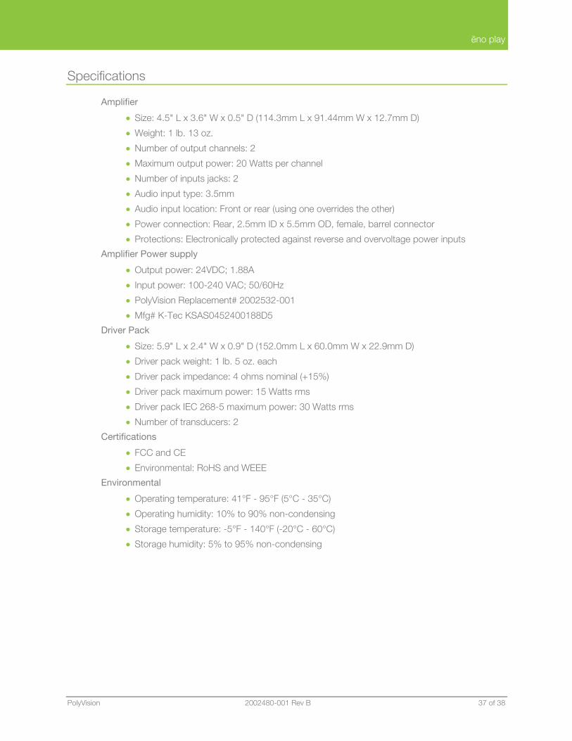
Specifications
Amplifier
• Size: 4.5" L x 3.6" W x 0.5" D (114.3mm L x 91.44mm W x 12.7mm D)
• Weight: 1 lb. 13 oz.
• Number of output channels: 2
• Maximum output power: 20 Watts per channel
• Number of inputs jacks: 2
• Audio input type: 3.5mm
• Audio input location: Front or rear (using one overrides the other)
• Power connection: Rear, 2.5mm ID x 5.5mm OD, female, barrel connector
• Protections: Electronically protected against reverse and overvoltage power inputs
Amplifier Power supply
• Output power: 24VDC; 1.88A
• Input power: 100-240 VAC; 50/60Hz
• PolyVision Replacement# 2002532-001
• Mfg# K-Tec KSAS0452400188D5
Driver Pack
• Size: 5.9" L x 2.4" W x 0.9" D (152.0mm L x 60.0mm W x 22.9mm D)
• Driver pack weight: 1 lb. 5 oz. each
• Driver pack impedance: 4 ohms nominal (+15%)
• Driver pack maximum power: 15 Watts rms
• Driver pack IEC 268-5 maximum power: 30 Watts rms
• Number of transducers: 2
Certifications
• FCC and CE
• Environmental: RoHS and WEEE
Environmental
• Operating temperature: 41°F - 95°F (5°C - 35°C)
• Operating humidity: 10% to 90% non-condensing
• Storage temperature: -5°F - 140°F (-20°C - 60°C)
• Storage humidity: 5% to 95% non-condensing

ēno play
38 of 38 2002480-001 Rev B Installation and Operation Guide
Index
adjustable height system cable management, 21 amplifier cable tie, 18 amplifier installation, 15 amplifier status LED, 29 audio input devices, 29 center cable tie, 18 driver pack cable connections, 16 driver pack cable ties, 17 driver pack installation, 10 foam strips, 25 guest audio connector, 30 install wall bracket extender, 24 LED status, 29
on-line registration, 3 PolyVision driver installation, 27 register with PolyVision, 3 removing driver packs or amp, 25 software installation, 27 software options, 29 system requirements;, 27 taping cables, 20 Ubuntu, 27 vibrations, 25 volume control, 29 wall bracket extenders, 24 what comes in the box, 6