Embed Size (px)
Citation preview
Produktový list Vydanie 14/11/2011 Identifikačné č.: 02 07 03 80 Sika® Waterbar WT
1 1/12 Tricosal® Elastomer tesniace pásy
Con
stru
ctio
n
Tricosal® Elastomer tesniace pásy Tesniace pásy na tesnenie škár vo vodonepriepustných konštrukciách podľa DIN 7865-1-2
Popis produktu Tricosal® Elastomer tesniace pásy sú trvalo flexibilné tesniace pásy zhotovené z elastomerov, SBR (styrén butadien guma) na tesnenie dilatačných a pracovných škár vo vodonepriepustných betónových konštrukciách. Sú k dispozícii v širokej škále rôznych typov, profilov a veľkostí pre možnosť výberu pre rôzne typy konštrukcií a pre rôzne alternatívy tesnenia škár.
Označenie ���� Tricosal® Elastomer tesniace pásy typ DIN 7865-1-2 SBR alebo iné elastomery
Použitie ���� Tesnenie škár v betónových konštrukciách
���� Tesnenie dilatačných a pracovných škár pri betonáži na stavbe
���� Napojenie nových a existujúcich konštrukcií pomocou Tricosal Elastomer tesniacich pásov s prírubou podľa DIN 7865-2
���� Typické konštrukcie:
- Základy komerčných budov, podzemné parkoviská
- Mosty, vrátane konštrukcií mostných žľabov
- Železničné a cestné tunely
- Čističky odpadových vôd
- Hrádze
- Elektrárne a priehrady (tesniace pásy v kombinácii s injektážnymi hadičkami pre možnosť dodatočného doinjektovania)
Charakteristiky/ výhody ���� Vysoká pevnosť v ťahu a prieťažnosť
���� Vysoká trvalá flexibilita a nd high resilience
���� Vhodné na vysoký tlak vody a namáhanie
���� Odolné voči všetkých prírodným médiam agresívnym pre betón
���� Odolné voči širokému spektru chemických prostriedkov (pre každú inú špecifickú situáciu je potrebné skúšanie)
���� Tvarovo stále v kontakte s horúcim bitumenom
���� Vulkanizácia pre spájanie tesniacich pásov na tupo na stavbe
Princípy použitia ���� Princípy pre návrh a zabudovanie podľa DIN V 18197
���� Tesniace systémy podľa DIN V 18197 a DIN 7865
2/12
Tricosal® Waterstops Elastomer
Con
stru
ctio
n
Skúšky
Osved čenia / normy DIN V 18197
DIN 7865-1-2
German WU Directive DAfStb.
ZTV-ING, RiZ-ING
German DS 804.6201 of DB AG
Vulcanizing instructions
Vulcanizing equipment instruction manual
Skúšobné certifikáty / osved čenia
Manufacturer’s test certificate
Certificate of Conformity DIN 7865
External monitoring by MPA NRW, Germany
Standard external monitoring inspection certificates
HPQ manufacturer based product qualification of DB AG, Germany
Specified for joint sealing in civil engineering structures according to ZTV-ING, RiZ-ING and DB AG RiLi 804.6201
Údaje o produkte
Forma
Chemická báza Standard Grades
SBR Elastomer based: Styrene Butadiene Rubber For internally and externally fixed waterstops
EPDM Elastomer based: Ethylene Propylene Diene Monomer rubber For exposed / capping joint waterstops FAE
Farba Black for internally and externally fixed waterstops
Black with grey visible surface for exposed / capping joint waterstops FAE
Balenie Dodávané v štandardných rolkách po 20, 25, 35 alebo 40 m v závislosti od profilu a od typu palety, na ktorej sa bude prepravovať.
Fabricated waterstopping systems in coils, on Euro or disposable pallets dependent on size
Skladovanie
Skladovacie podmienky / životnos ť
Stored on the pallets as supplied on a flat base
For long-term storage ≥ 6 months in enclosed areas: The recommendations of DIN 7716 apply.
The storage area should be covered, cool, dry, free from dust and moderately ventilated.
The Elastomer waterstops must be protected from heat sources and strong artificial lights with a high UV content.
Short-term storage > 6 weeks and < 6 months in enclosed areas: The principles of DIN 7716 apply.
On construction sites, outdoors:
- In dry storage, protected by suitable covers from direct sunlight, snow and ice, or any other form of contamination
- Store separate from other potentially harmful materials, plant and equipment such as structural steel, reinforcements or fuels etc.
- Store away from traffic and site roads
Short-term storage ≤ 6 weeks on construction sites, outdoors:
- Protected from contamination or damage
- Protected by suitable covers from strong sunlight, snow or ice etc.
Vulcanizing materials should be covered and stored in a cool, dry area free from dust and contamination. It is recommended that the stock requirements be coordinated for a maximum storage period of about 6 weeks.
3/12
Tricosal® Waterstops Elastomer
Con
stru
ctio
n
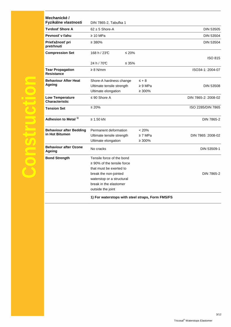
Mechanické / Fyzikálne vlastnosti DIN 7865-2, Tabuľka 1
Tvrdos ť Shore A 62 ± 5 Shore-A DIN 53505
Pevnos ť v ťahu ≥ 10 MPa DIN 53504
Prieťažnos ť pri pretrhnutí
≥ 380% DIN 53504
Compression Set 168 h / 23°C ≤ 20%
ISO 815
24 h / 70°C ≤ 35%
Tear Propagation Resistance
≥ 8 N/mm ISO34-1: 2004-07
Behaviour After Heat Ageing
Shore-A hardness change ≤ + 8
Ultimate tensile strength ≥ 9 MPa DIN 53508
Ultimate elongation ≥ 300%
Low Temperature Characteristic
≤ 90 Shore A DIN 7865-2: 2008-02
Tension Set ≤ 20% ISO 2285/DIN 7865
Adhesion to Metal 1) ≥ 1.50 kN DIN 7865-2
Behaviour after Bedding in Hot Bitumen
Permanent deformation < 20%
Ultimate tensile strength ≥ 7 MPa DIN 7865: 2008-02
Ultimate elongation ≥ 300%
Behaviour after Ozone Ageing
No cracks DIN 53509-1
Bond Strength Tensile force of the bond
≥ 90% of the tensile force
that must be exerted to
break the non-jointed DIN 7865-2
waterstop or a structural
break in the elastomer
outside the joint
1) For waterstops with steel straps, Form FMS/FS
4/12
Tricosal® Waterstops Elastomer
Con
stru
ctio
n
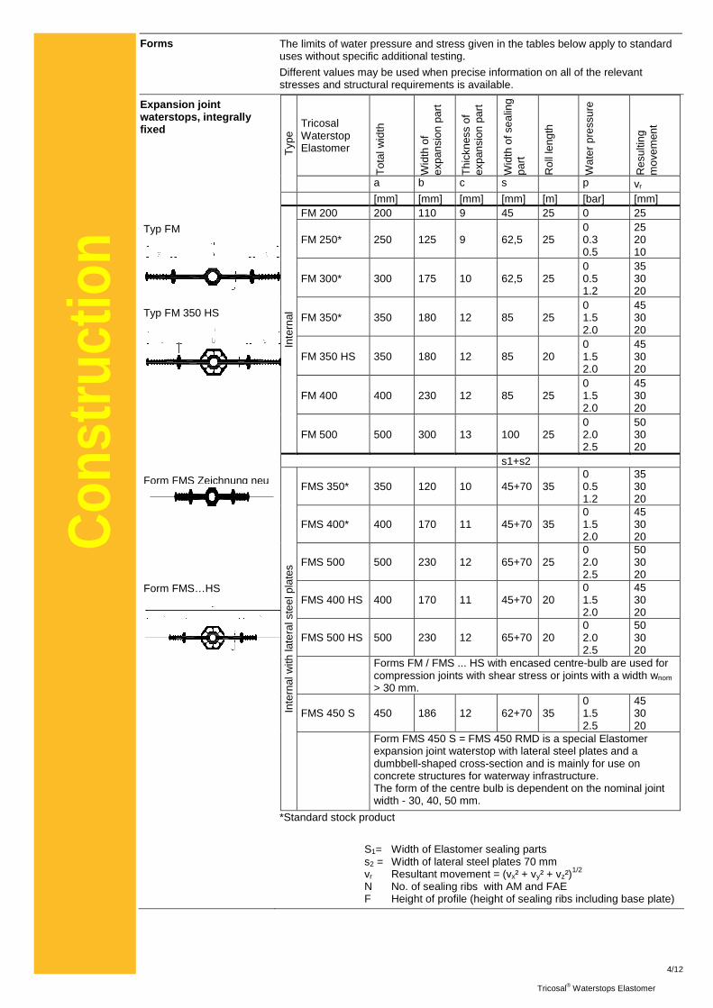
Forms The limits of water pressure and stress given in the tables below apply to standard uses without specific additional testing.
Different values may be used when precise information on all of the relevant stresses and structural requirements is available.
Expansion joint waterstops, integrally fixed Typ FM Typ FM 350 HS Form FMS Zeichnung neu
Form FMS…HS
Tricosal Waterstop Elastomer
Tot
al w
idth
Wid
th o
f ex
pans
ion
part
Thi
ckne
ss o
f ex
pans
ion
part
Wid
th o
f sea
ling
part
Rol
l len
gth
Wat
er p
ress
ure
Res
ultin
g m
ovem
ent
Typ
e
a b c s p vr [mm] [mm] [mm] [mm] [m] [bar] [mm]
FM 200 200 110 9 45 25 0 25
FM 250* 250 125 9 62,5 25 0 0.3 0.5
25 20 10
FM 300* 300 175 10 62,5 25 0 0.5 1.2
35 30 20
FM 350* 350 180 12 85 25 0 1.5 2.0
45 30 20
FM 350 HS 350 180 12 85 20 0 1.5 2.0
45 30 20
FM 400 400 230 12 85 25 0 1.5 2.0
45 30 20
Inte
rnal
FM 500 500 300 13 100 25 0 2.0 2.5
50 30 20
s1+s2
FMS 350* 350 120 10 45+70 35 0 0.5 1.2
35 30 20
FMS 400* 400 170 11 45+70 35 0 1.5 2.0
45 30 20
FMS 500 500 230 12 65+70 25 0 2.0 2.5
50 30 20
FMS 400 HS 400 170 11 45+70 20 0 1.5 2.0
45 30 20
FMS 500 HS 500 230 12 65+70 20 0 2.0 2.5
50 30 20
Forms FM / FMS ... HS with encased centre-bulb are used for compression joints with shear stress or joints with a width wnom > 30 mm.
FMS 450 S 450 186 12 62+70 35 0 1.5 2.5
45 30 20
Inte
rnal
with
late
ral s
teel
pla
tes
Form FMS 450 S = FMS 450 RMD is a special Elastomer expansion joint waterstop with lateral steel plates and a dumbbell-shaped cross-section and is mainly for use on concrete structures for waterway infrastructure. The form of the centre bulb is dependent on the nominal joint width - 30, 40, 50 mm.
*Standard stock product
S1= Width of Elastomer sealing parts s2 = Width of lateral steel plates 70 mm vr Resultant movement = (vx² + vy² + vz²)
1/2 N No. of sealing ribs with AM and FAE F Height of profile (height of sealing ribs including base plate)
5/12
Tricosal® Waterstops Elastomer
Con
stru
ctio
n
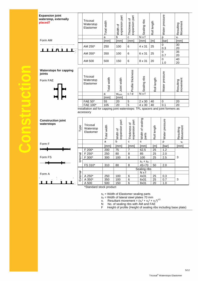
Expansion joint waterstop, externally placed7 Form AM Waterstops for capping joints Form FAE Construction joint waterstops Form F Form FS Form A
Tricosal Waterstop Elastomer
Tot
al w
idth
Wid
th o
f ex
pans
ion
part
Thi
ckne
ss o
f ex
pans
ion
part
Sea
ling
ribs
Rol
l len
gth
Wat
er p
ress
ure
Res
ultin
g M
ovem
ent
a b c N x f p vr [mm] [mm] [mm] [mm] [m] [bar] [mm]
AM 250* 250 100 6 4 x 31 25 0 0.3
30 20
AM 350* 350 100 6 6 x 31 25 0 0.7
35 20
AM 500 500 150 6 8 x 31 20 0
1.0 40 20
Tricosal Waterstop Elastomer
Tot
al w
idth
Join
t wid
th
Pro
file
thic
knes
s
Sea
ling
ribs
Rol
l len
gth
Wat
er p
ress
ure
Res
ultin
g m
ovem
ent
a wnom c / d N x f [mm] [mm]
FAE 50* 55 20 5 2 x 30 40 0 20 FAE 100* 105 20 5 4 x 30 40 0.1 20
Installation aid for capping joint waterstops: TFL spacers and joint formers as accessory
Typ
e Tricosal Waterstop Elastomer
Tot
al w
idth
Wid
th o
f ex
pans
ion
part
Thi
ckne
ss o
f ex
pans
ion
part
Wid
th o
f sea
ling
part
s
Rol
l len
gth
Wat
er p
ress
ure
Res
ultin
g M
ovem
ent
a b c s p vr [mm] [mm] [mm] [mm] [m] [bar] [mm]
F 200* 200 75 7 62,5 25 1.2 F 250* 250 80 8 85 25 2.0 F 300* 300 100 8 100 25 2.5 s1 + s2 In
tern
al
FS 310* 310 80 8 45+70 50 2.0
3
Sealing ribs N x f A 250* 250 100 6 4x31 25 0.3 A 350* 350 100 6 6x31 25 0.7 E
xter
nal
A 500 500 150 6 8x31 20 1.0 3
*Standard stock product s1 = Width of Elastomer sealing parts s2 = Width of lateral steel plates 70 mm vr Resultant movement = (vx² + vy² + vz²)
1/2 N No. of sealing ribs with AM and FAE F Height of profile (Height of sealing ribs including base plate)
6/12
Tricosal® Waterstops Elastomer
Con
stru
ctio
n
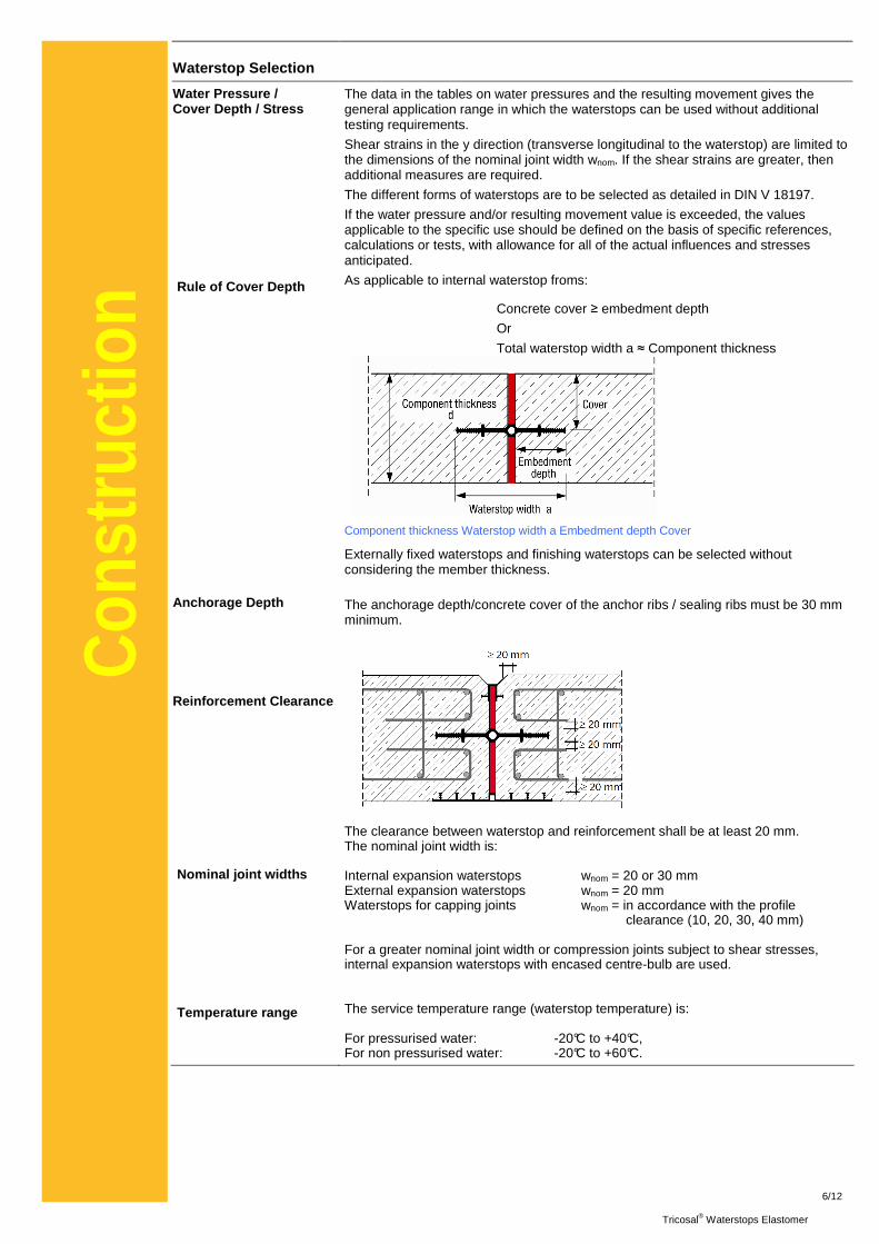
Waterstop Selection
Water Pressure / Cover Depth / Stress
Rule of Cover Depth
Anchorage Depth
Reinforcement Clearance
Nominal joint widths
Temperature range
The data in the tables on water pressures and the resulting movement gives the general application range in which the waterstops can be used without additional testing requirements.
Shear strains in the y direction (transverse longitudinal to the waterstop) are limited to the dimensions of the nominal joint width wnom. If the shear strains are greater, then additional measures are required.
The different forms of waterstops are to be selected as detailed in DIN V 18197.
If the water pressure and/or resulting movement value is exceeded, the values applicable to the specific use should be defined on the basis of specific references, calculations or tests, with allowance for all of the actual influences and stresses anticipated.
As applicable to internal waterstop froms:
Concrete cover ≥ embedment depth
Or
Total waterstop width a ≈ Component thickness Component thickness Waterstop width a Embedment depth Cover
Externally fixed waterstops and finishing waterstops can be selected without considering the member thickness.
The anchorage depth/concrete cover of the anchor ribs / sealing ribs must be 30 mm minimum.
The clearance between waterstop and reinforcement shall be at least 20 mm. The nominal joint width is: Internal expansion waterstops wnom = 20 or 30 mm External expansion waterstops wnom = 20 mm Waterstops for capping joints wnom = in accordance with the profile clearance (10, 20, 30, 40 mm) For a greater nominal joint width or compression joints subject to shear stresses, internal expansion waterstops with encased centre-bulb are used. The service temperature range (waterstop temperature) is: For pressurised water: -20°C to +40°C, For non pressurised water: -20°C to +60°C.
7/12
Tricosal® Waterstops Elastomer
Con
stru
ctio
n
Special stresses and exposure
Exposure to Different Temperatures and Chemical Agents
For special stresses and exposures due to different temperatures and/or chemical mediums outside the substances or situations specifically defined in DIN 4033. Separate tests are always necessary. Where required other materials are available in addition to the standard SBR (styrene butadiene rubber).
Tricosal Elastomer waterstops made from materials ot her than the standard SBR Grade are produced to order when required. They are not held in stock.
Informácie o systéme
Only butt joints should be formed on site with Tricosal Elastomer waterstops; the other junctions / joints should all be factory produced.
The factory production of different waterstop systems and junctions reduces the joints required to be formed on site to a minimum.
Special junctions or waterstopping systems can be factory produced for specific projects.
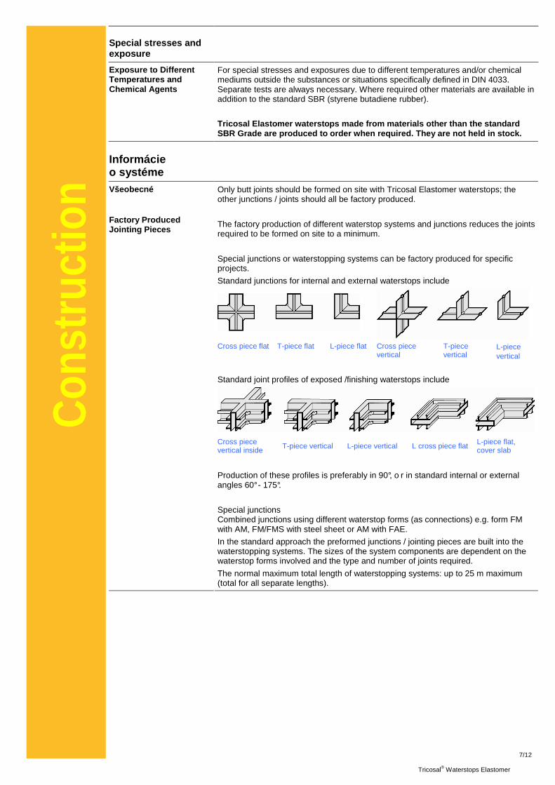
Standard junctions for internal and external waterstops include
Cross piece flat T-piece flat L-piece flat Cross piece vertical
T-piece vertical
L-piece vertical
Standard joint profiles of exposed /finishing waterstops include
Cross piece vertical inside T-piece vertical L-piece vertical L cross piece flat L-piece flat,
cover slab
Všeobecné
Factory Produced Jointing Pieces
Production of these profiles is preferably in 90°, o r in standard internal or external angles 60° - 175°.
Special junctions Combined junctions using different waterstop forms (as connections) e.g. form FM with AM, FM/FMS with steel sheet or AM with FAE.
In the standard approach the preformed junctions / jointing pieces are built into the waterstopping systems. The sizes of the system components are dependent on the waterstop forms involved and the type and number of joints required.
The normal maximum total length of waterstopping systems: up to 25 m maximum (total for all separate lengths).
8/12
Tricosal® Waterstops Elastomer
Con
stru
ctio
n
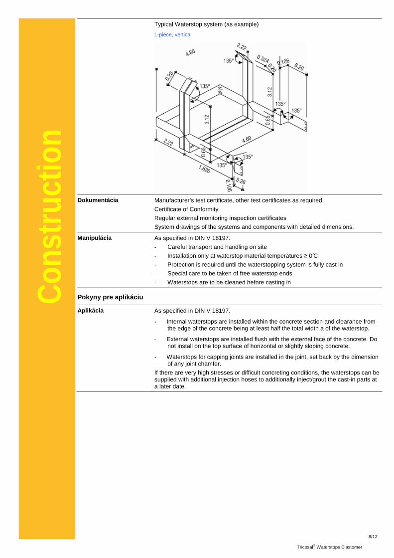
Typical Waterstop system (as example)
L-piece, vertical
Dokumentácia Manufacturer’s test certificate, other test certificates as required
Certificate of Conformity
Regular external monitoring inspection certificates
System drawings of the systems and components with detailed dimensions.
Manipulácia As specified in DIN V 18197.
- Careful transport and handling on site
- Installation only at waterstop material temperatures ≥ 0°C
- Protection is required until the waterstopping system is fully cast in
- Special care to be taken of free waterstop ends
- Waterstops are to be cleaned before casting in
Pokyny pre aplikáciu
Aplikácia As specified in DIN V 18197.
- Internal waterstops are installed within the concrete section and clearance from the edge of the concrete being at least half the total width a of the waterstop.
- External waterstops are installed flush with the external face of the concrete. Do not install on the top surface of horizontal or slightly sloping concrete.
- Waterstops for capping joints are installed in the joint, set back by the dimension of any joint chamfer.
If there are very high stresses or difficult concreting conditions, the waterstops can be supplied with additional injection hoses to additionally inject/grout the cast-in parts at a later date.
9/12
Tricosal® Waterstops Elastomer
Con
stru
ctio
n
Jointing on Site: Site Joints
The Elastomer waterstops are butt jointed together by vulcanization, i.e. with added Tricosal rubber strips and the action of heat and pressure in a site vulcanizing equipment with moulds dependent on the profile used and longitudinal strain and specified vulcanizing parameters for the specific forms (temperature and time).
Jointing with other vulcanizing agents without heat or using adhesives or adhesive tape is not permitted.
Site joints must only be formed as stated in the vulcanizing instructions.
Requirement: Minimum ambient temperature + 5 °C and dry weather conditions.
Site joints must be formed only by trained and qualified personnel.
The key steps in the vulcanizing for all Tricosal Elastomer waterstopping forms FM/F, FMS/FS, FMS…HS, AM/A, FAE are fully described in the detailed instructions.
These key steps for site jointing complying with the vulcanizing instructions are:
Cut the waterstop ends, straight and square Roughen the waterstop ends on the front, top and bottom Grind the steel plates until smooth, for FMS/FS
Application of vulcanizing solvent, For FMS/FS also Apply 2 coats of bonding agent before application of vulcanizing solvent Plug the centre bulb with a foam stopper and Elastomer stopper from adhesion foil Apply the bonding agent on the front Bring together the waterstop ends and apply the tensioning harness Wrap in strip tape 0 Wrap in strip tape 1 Sprinkle the wrapped joint with talcum release agent Place the prepared joint in the preheated vulcanizing equipment with the oulds for the form Vulcanize the butt joint for about 35 minutes Remove from the vulcanizing equipment Cool (by ambient temperature - do not use coolant)
After cooling for about half an hour, the joint is finished and may be fixed / installed / stressed.
Further steps may be necessary dependent on the specific jointing requirements and the waterstop form.
The vulcanizing instructions are enclosed with the vulcanizing equipment.
All vulcanizing work is subject to the relevant local Health and Safety regulations and the Equipment and Materials Safety Information.
Formation of these site joints takes about 1 – 2 hours of working time per joint dependent on the specific waterstop form and therefore this time must be scheduled and the work completed properly before the next operations proceed.
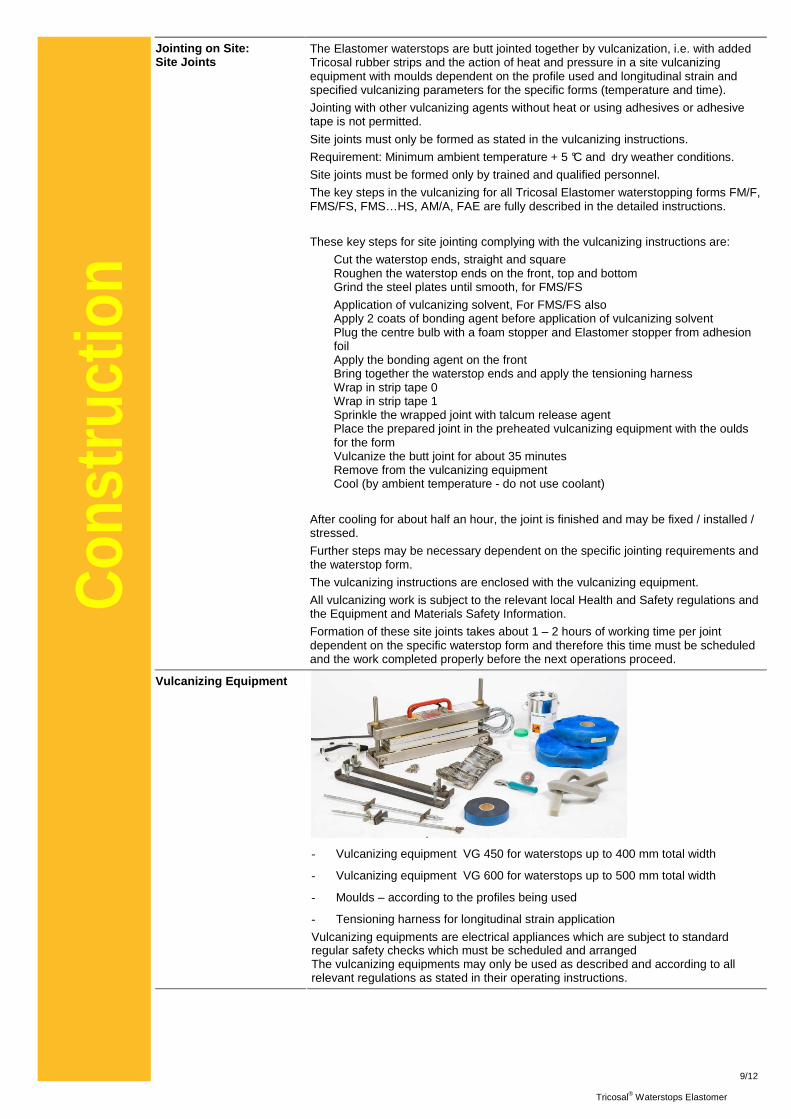
- Vulcanizing equipment VG 450 for waterstops up to 400 mm total width
- Vulcanizing equipment VG 600 for waterstops up to 500 mm total width
- Moulds – according to the profiles being used
- Tensioning harness for longitudinal strain application
Vulcanizing Equipment
Vulcanizing equipments are electrical appliances which are subject to standard regular safety checks which must be scheduled and arranged The vulcanizing equipments may only be used as described and according to all relevant regulations as stated in their operating instructions.
10/12
Tricosal® Waterstops Elastomer
Con
stru
ctio
n
Tools, other Supplies and Protective Clothing
Cutting Tape measure, metre ruler, set square,marker pen, rubber cutter
Roughening Goggles, protective gloves, hand drill, abrasive gel/carbide abrasive wheel with mounting
Removing abrasion dust
Hand brush or paintbrush Vulcanizing solution Paintbrush/round brush with long bristles Adhesion foil Scissors, roller 4 mm Cover strip Scissors, roller 4 mm and roller 12 mm
Tensioning the vulcanizing equipment
Screwdriver/ring spanner SW 32 Heat insulated gloves Demoulding Screwdriver
Additionally for the waterstop forms FMS/FS with lateral steel plates:
Cutting Jigsaw with metal blade
Preparation of steel plates: Angle grinder with steel roughing disc (small unit) Priming Paintbrush/round brush with long bristles Bonding agent Paintbrush/round brush with long bristles
Welding the steel plates: Thin plate welding jig, gas or solid rod electrodes Welder’s protective clothing
Vulcanizing Materials Stopper Profile 1 metre Heat solution Can ca. 1 kg Adhesion foil 35 x 0.6 mm Roll ca. 33 m Cover strip 035 x 2 mm Roll ca. 26 m Cover strip 150 x 2.5 mm Roll ca. 27 m Talcum PE bottle ca. 200 g
For waterstops FMS with lateral steel plates Priming Can ca. 250 g Bonding agent Can ca. 250 g
Vulcanizing materials are supplied to order and the quantity stocked should be based on a 6-week usage requirement.
Vulcanizing material is non-vulcanized raw rubber and must be stored in a cool, dry, dark area free from dust.
11/12
Tricosal® Waterstops Elastomer
Con
stru
ctio
n
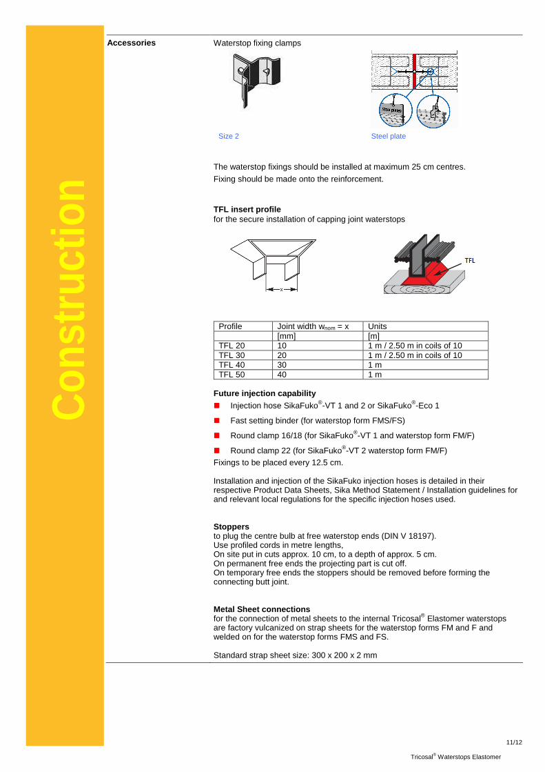
Accessories Waterstop fixing clamps
Size 2 Steel plate
The waterstop fixings should be installed at maximum 25 cm centres.
Fixing should be made onto the reinforcement.
TFL insert profile for the secure installation of capping joint waterstops
Profile Joint width wnom = x Units [mm] [m] TFL 20 10 1 m / 2.50 m in coils of 10 TFL 30 20 1 m / 2.50 m in coils of 10 TFL 40 30 1 m TFL 50 40 1 m
Future injection capability ���� Injection hose SikaFuko®-VT 1 and 2 or SikaFuko®-Eco 1
���� Fast setting binder (for waterstop form FMS/FS)
���� Round clamp 16/18 (for SikaFuko®-VT 1 and waterstop form FM/F)
���� Round clamp 22 (for SikaFuko®-VT 2 waterstop form FM/F) Fixings to be placed every 12.5 cm. Installation and injection of the SikaFuko injection hoses is detailed in their respective Product Data Sheets, Sika Method Statement / Installation guidelines for and relevant local regulations for the specific injection hoses used. Stoppers to plug the centre bulb at free waterstop ends (DIN V 18197). Use profiled cords in metre lengths, On site put in cuts approx. 10 cm, to a depth of approx. 5 cm. On permanent free ends the projecting part is cut off. On temporary free ends the stoppers should be removed before forming the connecting butt joint. Metal Sheet connections for the connection of metal sheets to the internal Tricosal® Elastomer waterstops are factory vulcanized on strap sheets for the waterstop forms FM and F and welded on for the waterstop forms FMS and FS. Standard strap sheet size: 300 x 200 x 2 mm
12/12
Tricosal® Waterstops Elastomer
Con
stru
ctio
n
Miestne obmedzenia
Prosím všimnite si, že v dôsledku špecifických miestnych podmienok sa správanie tohto produktu môže meniť v závislosti od krajiny. Prosím vyžiadajte si na miestny produktový list pre presný popis aplikácie.
Informácie o ochrane zdravia a bezpečnosti
Podrobné informácie ohľadom bezpečnosti a ochrany zdravia ako aj podrobné preventívne opatrenia, ako napr. fyzikálne, toxikologické a ekologické údaje sú uvedené v karte bezpečnostných údajov materiálu.
Právne oznámenia Informácie, a najmä odporúčania, vzťahujúce sa na aplikáciu a konečné využitie Sika produktov sa podávajú v dobrej viere vyplývajúcej zo súčasných poznatkov a skúseností s výrobkami pri správnom skladovaní, manipulácii a aplikácii za normálnych podmienok v súlade s doporučeniami Sika.
V praxi rozdiely v materiáloch, substrátoch a v skutočných podmienkach na stavbe sú také, že nemôže byť poskytnutá žiadna záruka, čo sa týka predajnosti alebo vhodnosti a použiteľnosti pre určitý účel, ani žiadny záväzok vyplývajúci z akéhokoľvek právneho vzťahu. Nemôže byť vyvodený žiadny záväzok ani z tejto informácie, ani zo žiadnych písomných odporúčaní alebo poskytnutých rád. Spracovávateľ produktu musí overiť vhodnosť produktu pre plánované použitie a účel. Sika si vyhradzuje právo na zmenu vlastností jej produktov.
Vlastnícke práva tretích strán musia byť dodržané. Všetky objednávky sa akceptujú podliehajúc našim platným všeobecným a obchodným podmienkam. Užívatelia by sa mali vždy odvolávať na posledné vydanie miestnych produktových listov pre konkrétny výrobok.