Embed Size (px)
Citation preview
Rev.0 20Jan2015 GT Projectors 2015 Page 1 of 29
Porsche 986 & 996 Headlights
Bi-xenon HID conversion
Converting a headlight consists of:
1. Opening the headlight
2. Painting (if desired)
3. Installing the projector
4. Installing the ballast
5. Wiring
6. Testing
7. Initial leveling
8. Cleaning and sealing
9. Final leveling
Parts in kit:
1. Bezels (shrouds)with MH1 projectors
2. 35w ballasts (if ordered)
3. H1 HID bulbs (if ordered)
4. Hardware kit:
o spacer kit
o sanding wheels for rotary tool
o two Porsche emblems
Materials not supplied:
1. Paint (if required) in aerosol cans
o Plastic primer (Rustoleum, PlastiKote or equal)
o High temperature paint (Rustoleum High Heat Engine Enamel, PlastiKote
Engine Enamel, or equal)
2. Sandpaper (if painting; see Section 2)
3. RTV sealant (Permatex Black Silicone Adhesive Sealant, 3M Ultrapro Silicon
Gasket or equal)
4. Clean plastic bags big enough to fit the main outer lens
5. Thread locker (Loctite Blue or equal)
6. Misc small hardware, zip ties (if mounting ballast outside headlight; see Section
4)
7. Wire connectors, spade type, 0.250" male, for 18-22 ga. wire
Rev.0 20Jan2015 GT Projectors 2015 Page 2 of 29
Tools required:
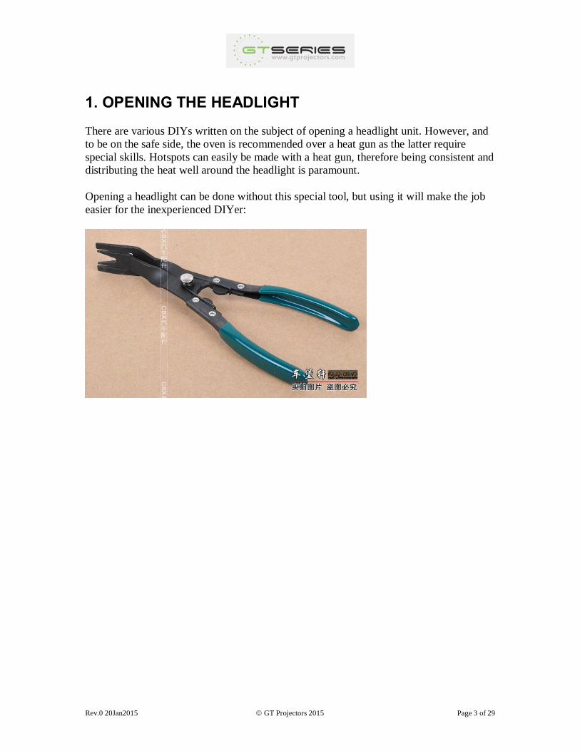
1. Special tool for opening sealed headlights (as shown below), or small flat metal
pry bars, flat bladed screwdrivers and putty knife. Plastic body tools are not
recommended as they are too flexible.
2. Rotary tool (Dremel or equal)
3. Rotary tool accessory: 536 Brass Brush. (optional)
4. Rotary tool accessory: thin flat cutoff disc (optional; for mounting ballast outside
headlight)
5. 3/4 - 1" drill or hole saw (optional; for mounting ballast outside headlight)
6. Regular and needle nose pliers
7. Screwdrivers
8. Utility knife
9. Tape measure
10. Mini-spirit level (optional)
11. Air compressor (optional)
Safety
Wear all appropriate personal protective equipment, including gloves, eye protection,
dust masks, etc. as required. Follow the manufacturer's safety instructions for all tools.
READ THROUGH ALL OF THE INSTRUCTIONS BEFORE STARTING THE
PROJECT.
Rev.0 20Jan2015 GT Projectors 2015 Page 3 of 29
1. OPENING THE HEADLIGHT
There are various DIYs written on the subject of opening a headlight unit. However, and
to be on the safe side, the oven is recommended over a heat gun as the latter require
special skills. Hotspots can easily be made with a heat gun, therefore being consistent and
distributing the heat well around the headlight is paramount.
Opening a headlight can be done without this special tool, but using it will make the job
easier for the inexperienced DIYer:
Rev.0 20Jan2015 GT Projectors 2015 Page 4 of 29
1. Remove the headlight assembly from the car using the instructions found in the user's
manual and the special tool from the car's tool kit.
2. Clean the headlight assembly with a soft sponge and warm, soapy water.
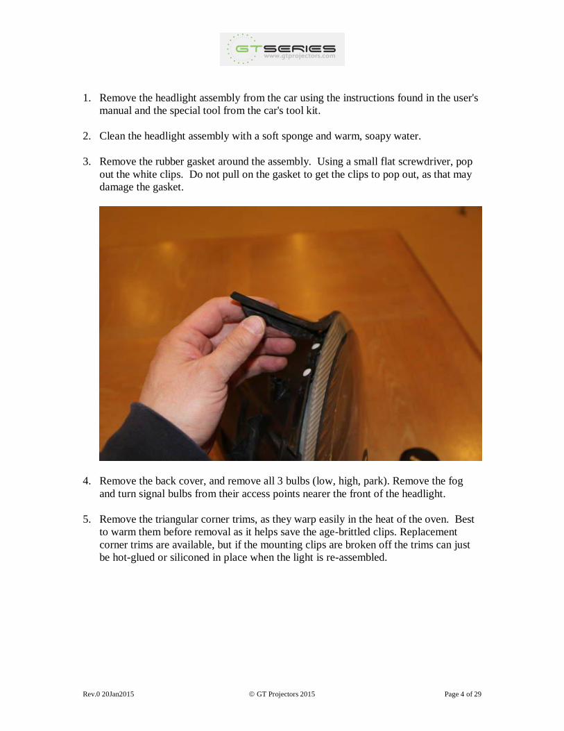
3. Remove the rubber gasket around the assembly. Using a small flat screwdriver, pop
out the white clips. Do not pull on the gasket to get the clips to pop out, as that may
damage the gasket.
4. Remove the back cover, and remove all 3 bulbs (low, high, park). Remove the fog
and turn signal bulbs from their access points nearer the front of the headlight.
5. Remove the triangular corner trims, as they warp easily in the heat of the oven. Best
to warm them before removal as it helps save the age-brittled clips. Replacement
corner trims are available, but if the mounting clips are broken off the trims can just
be hot-glued or siliconed in place when the light is re-assembled.
Rev.0 20Jan2015 GT Projectors 2015 Page 5 of 29
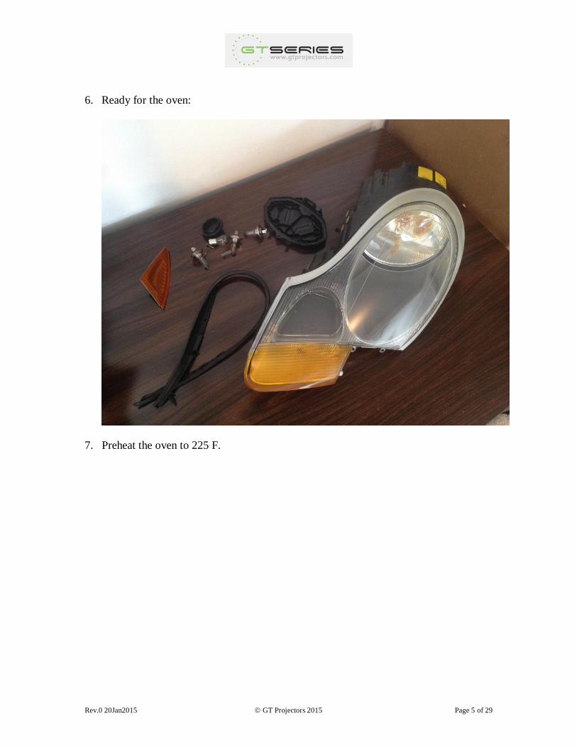
6. Ready for the oven:
7. Preheat the oven to 225 F.
Rev.0 20Jan2015 GT Projectors 2015 Page 6 of 29
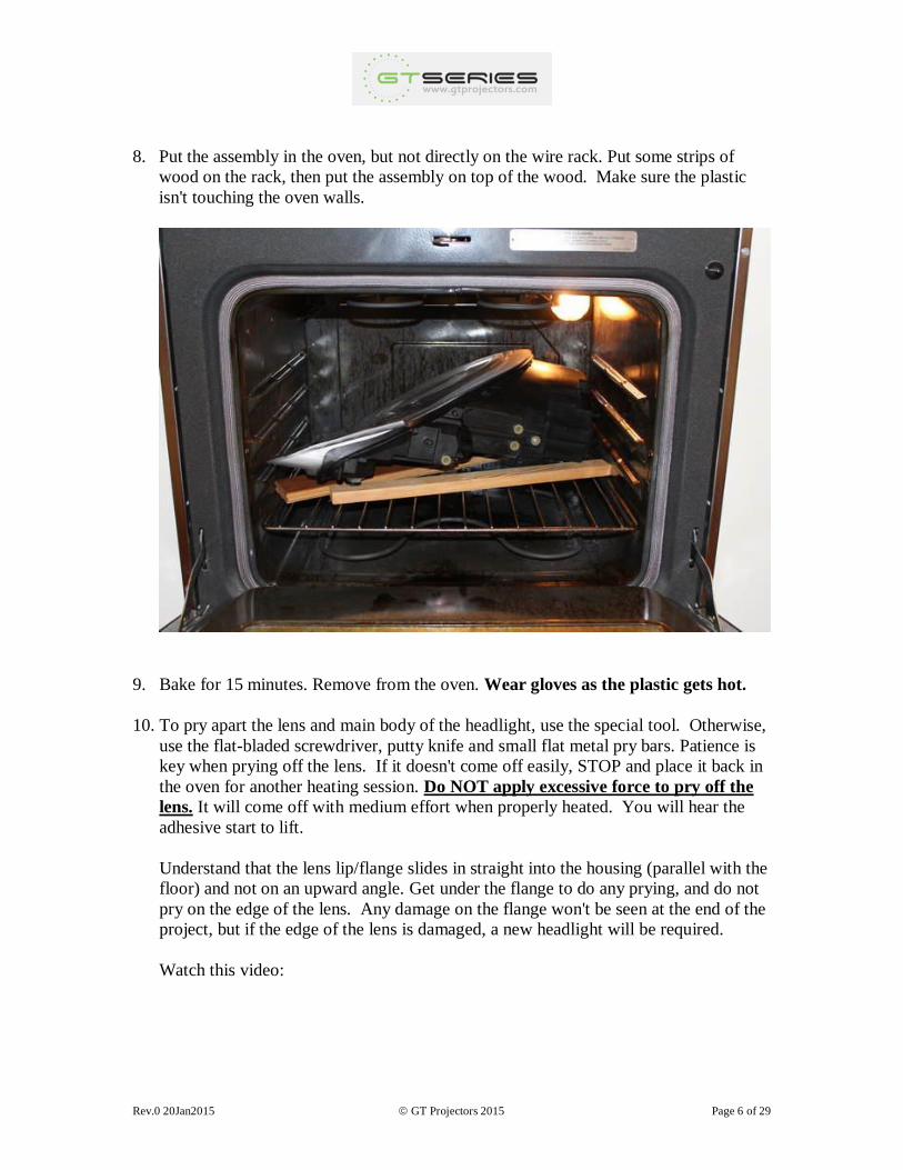
8. Put the assembly in the oven, but not directly on the wire rack. Put some strips of
wood on the rack, then put the assembly on top of the wood. Make sure the plastic
isn't touching the oven walls.
9. Bake for 15 minutes. Remove from the oven. Wear gloves as the plastic gets hot.
10. To pry apart the lens and main body of the headlight, use the special tool. Otherwise,
use the flat-bladed screwdriver, putty knife and small flat metal pry bars. Patience is
key when prying off the lens. If it doesn't come off easily, STOP and place it back in
the oven for another heating session. Do NOT apply excessive force to pry off the
lens. It will come off with medium effort when properly heated. You will hear the
adhesive start to lift.
Understand that the lens lip/flange slides in straight into the housing (parallel with the
floor) and not on an upward angle. Get under the flange to do any prying, and do not
pry on the edge of the lens. Any damage on the flange won't be seen at the end of the
project, but if the edge of the lens is damaged, a new headlight will be required.
Watch this video:

Rev.0 20Jan2015 GT Projectors 2015 Page 7 of 29
Rev.0 20Jan2015 GT Projectors 2015 Page 8 of 29
Take your time and be careful not to touch the inside of the lens and don't let any
tools contact the back of the silver perimeter of the lens as this can scratch the paint
and will be very obvious on the finished headlight. It's next to impossible to touch up
the silver paint to its original look.
11. Remove the outer lens and set it aside carefully.
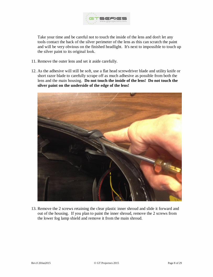
12. As the adhesive will still be soft, use a flat head screwdriver blade and utility knife or
short razor blade to carefully scrape off as much adhesive as possible from both the
lens and the main housing. Do not touch the inside of the lens! Do not touch the
silver paint on the underside of the edge of the lens!
13. Remove the 2 screws retaining the clear plastic inner shroud and slide it forward and
out of the housing. If you plan to paint the inner shroud, remove the 2 screws from
the lower fog lamp shield and remove it from the main shroud.
Rev.0 20Jan2015 GT Projectors 2015 Page 9 of 29
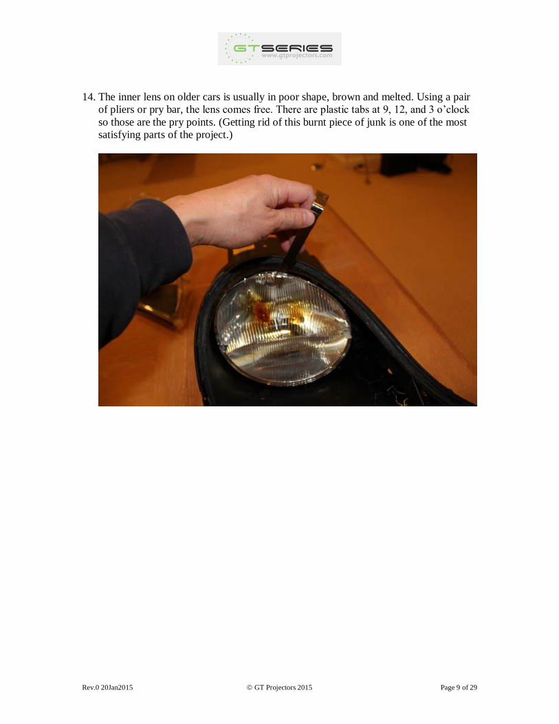
14. The inner lens on older cars is usually in poor shape, brown and melted. Using a pair
of pliers or pry bar, the lens comes free. There are plastic tabs at 9, 12, and 3 o’clock
so those are the pry points. (Getting rid of this burnt piece of junk is one of the most
satisfying parts of the project.)
Rev.0 20Jan2015 GT Projectors 2015 Page 10 of 29
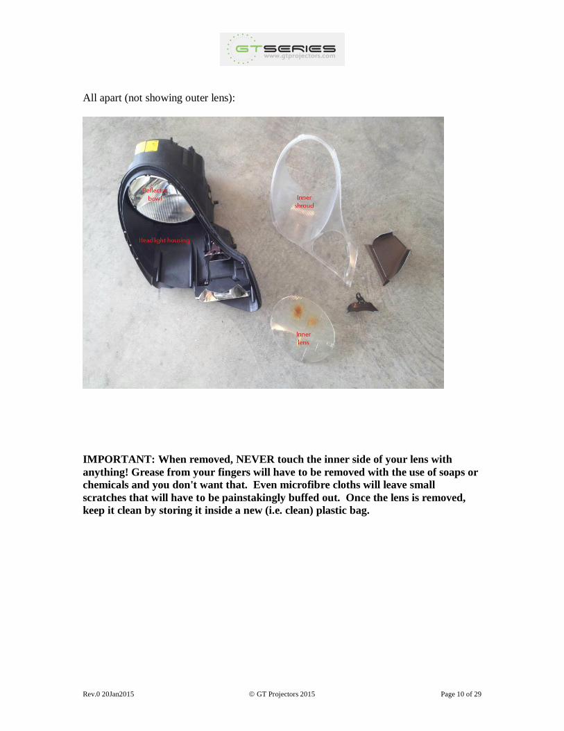
All apart (not showing outer lens):
IMPORTANT: When removed, NEVER touch the inner side of your lens with
anything! Grease from your fingers will have to be removed with the use of soaps or
chemicals and you don't want that. Even microfibre cloths will leave small
scratches that will have to be painstakingly buffed out. Once the lens is removed,
keep it clean by storing it inside a new (i.e. clean) plastic bag.
Rev.0 20Jan2015 GT Projectors 2015 Page 11 of 29
2. PAINTING
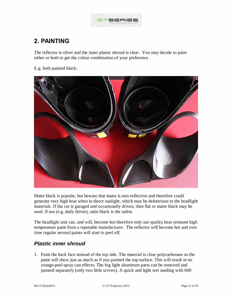
The reflector is silver and the inner plastic shroud is clear. You may decide to paint
either or both to get the colour combination of your preference.
E.g. both painted black:
Matte black is popular, but beware that matte is non-reflective and therefore could
generate very high heat when in direct sunlight, which may be deleterious to the headlight
materials. If the car is garaged and occasionally driven, then flat or matte black may be
used. If not (e.g. daily driver), satin black is the safest.
The headlight unit can, and will, become hot therefore only use quality heat resistant high
temperature paint from a reputable manufacturer. The reflector will become hot and over
time regular aerosol paints will start to peel off.
Plastic inner shroud
1. Paint the back face instead of the top side. The material is clear polycarbonate so the
paint will show just as much as if you painted the top surface. This will result in no
orange-peel spray can effects. The fog light aluminum parts can be removed and
painted separately (only two little screws). A quick and light wet sanding with 600
Rev.0 20Jan2015 GT Projectors 2015 Page 12 of 29
grit on the smooth portion only (sanding the ridges can result in flat spots that can be
seen in the finished product). Just a quick pass, nothing too vigorous.
2. Plastic primer. Follow manufacturer's instructions. For Rustoleum, 2 coats, 30
minutes between coats and a light sanding with 1200 to smooth out if you want (this
doesn't make much difference in the final finish if using the Rustoleum black below,
so sanding between coats isn't necessary). Alternative product: PlastiKote Plastic
Primer.
3. High temperature paint. Follow manufacturer's instructions. For Rustoleum High
Heat Engine Enamel, 3-5 coats, 30-45 minutes between coats. Don't wait too long -
more than 2 hours in between coats - or the solvent in the new coat will melt the
previous coats and make a mess that will require complete stripping and starting over.
Alternative product: PlastiKote Engine Enamel.
Tip: if debris ends up in the paint (random hair or fuzz), use tweezers to remove it, then
let the coat dry for 90 minutes. Use a plastic cylindrical object (Bic ballpoint pens with
straight shafts work great) as a rolling pin to carefully roll over the defect left in the paint
from removing the debris while applying pressure to flatten it out smooth, then apply the
next coat or a quick spritz to cover it if on final coat. This works great to remove small
bubble or divot defects on smooth surfaces, as long as it's done when the paint is dry
enough to not stick to the roller, but fresh enough that it's still malleable.
Reflector bowl
You don't have to remove the reflector bowl to paint it. There is no problem getting paint
on the unit just in front of the bowl. When assembled there is a 3/4" gap between the
bowl and the clear plastic inner shroud, which can also be painted, and should be painted
if any colour other than black is used. Lift the bowl to its highest position using the
headlight adjustment hex screw (lower one) so that the spray can reach under the bowl.
You may want to mask other parts of the headlight assembly to avoid excess paint spray.
Be careful when working on the reflector. The bowl is mounted by 3 balls in sockets. It's
possible to remove the bowl from the headlight but, as this plastic material stiffens with
age, removal is not recommended for older units. If for some reason you hear a pop
while working with the unit and the reflector becomes loose, very gently push the ball
back into the socket.
1. Preparation: Sand off the chrome finish. This will ensure that the paint will adhere
properly and no chemical reaction will occur between the chrome and the paint.
Some paints react to the chrome on some reflectors.
Rev.0 20Jan2015 GT Projectors 2015 Page 13 of 29
A fast and easy method for this is to use this attachment on your Dremel tool: 536
Brass Brush. Use light sweeps. Don't hold it in any one place for too long (to avoid
burning) and it zips the chrome off quickly. This is especially helpful in the
corrugated areas. Sandpaper will do the job as well, but takes more time.
Otherwise, a moderate sanding with 200-300 grit sandpaper to remove at least 50-
75% of the chrome, then a quick pass on the lower half with 600 to smooth it out (the
upper half will not be visible in the finished headlight).
2. Painting: primer and 4-6 coats of the same paint used for the shroud.
Rev.0 20Jan2015 GT Projectors 2015 Page 14 of 29
3. INSTALLING THE PROJECTOR
NOTE: ensure that the new projectors are not in close proximity when using compressed
air for cleaning. Any dust may end up inside them and they will have to be disassembled
for cleaning.
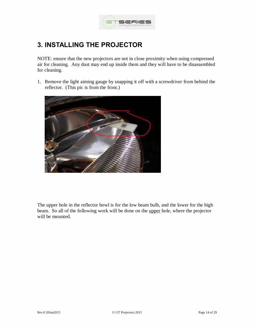
1. Remove the light aiming gauge by snapping it off with a screwdriver from behind the
reflector. (This pic is from the front.)
The upper hole in the reflector bowl is for the low beam bulb, and the lower for the high
beam. So all of the following work will be done on the upper hole, where the projector
will be mounted.
Rev.0 20Jan2015 GT Projectors 2015 Page 15 of 29
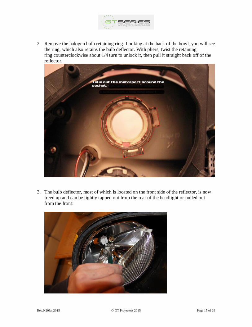
2. Remove the halogen bulb retaining ring. Looking at the back of the bowl, you will see
the ring, which also retains the bulb deflector. With pliers, twist the retaining
ring counterclockwise about 1/4 turn to unlock it, then pull it straight back off of the
reflector.
3. The bulb deflector, most of which is located on the front side of the reflector, is now
freed up and can be lightly tapped out from the rear of the headlight or pulled out
from the front:
Rev.0 20Jan2015 GT Projectors 2015 Page 16 of 29
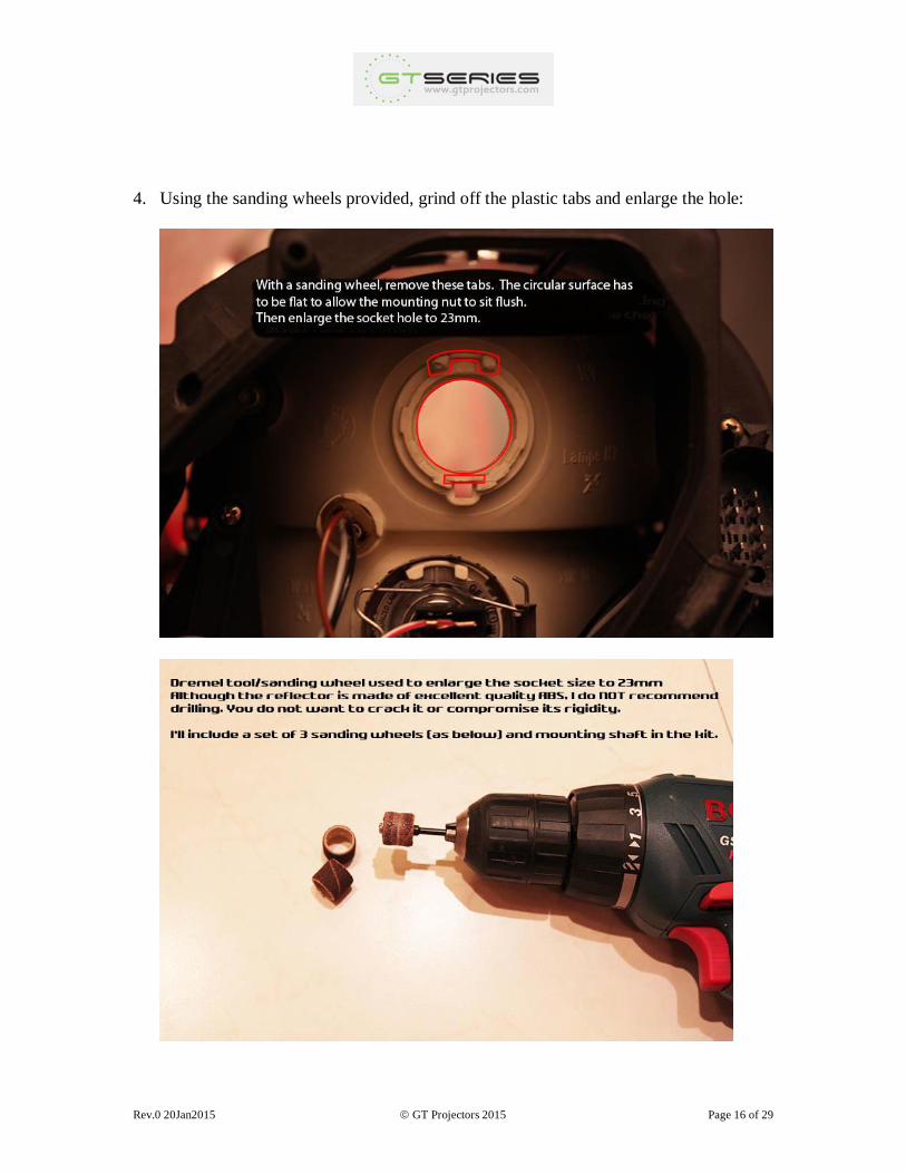
4. Using the sanding wheels provided, grind off the plastic tabs and enlarge the hole:
Rev.0 20Jan2015 GT Projectors 2015 Page 17 of 29
Do not enlarge the socket on the reflector to more than 23mm. You don't need to
measure the opening, just keep trying to fit the projector shaft (or equivalent diameter
cylinder) into the bore as you're opening it up. Visually use the outer ring of plastic
as a guide to keep the expanding hole concentric.
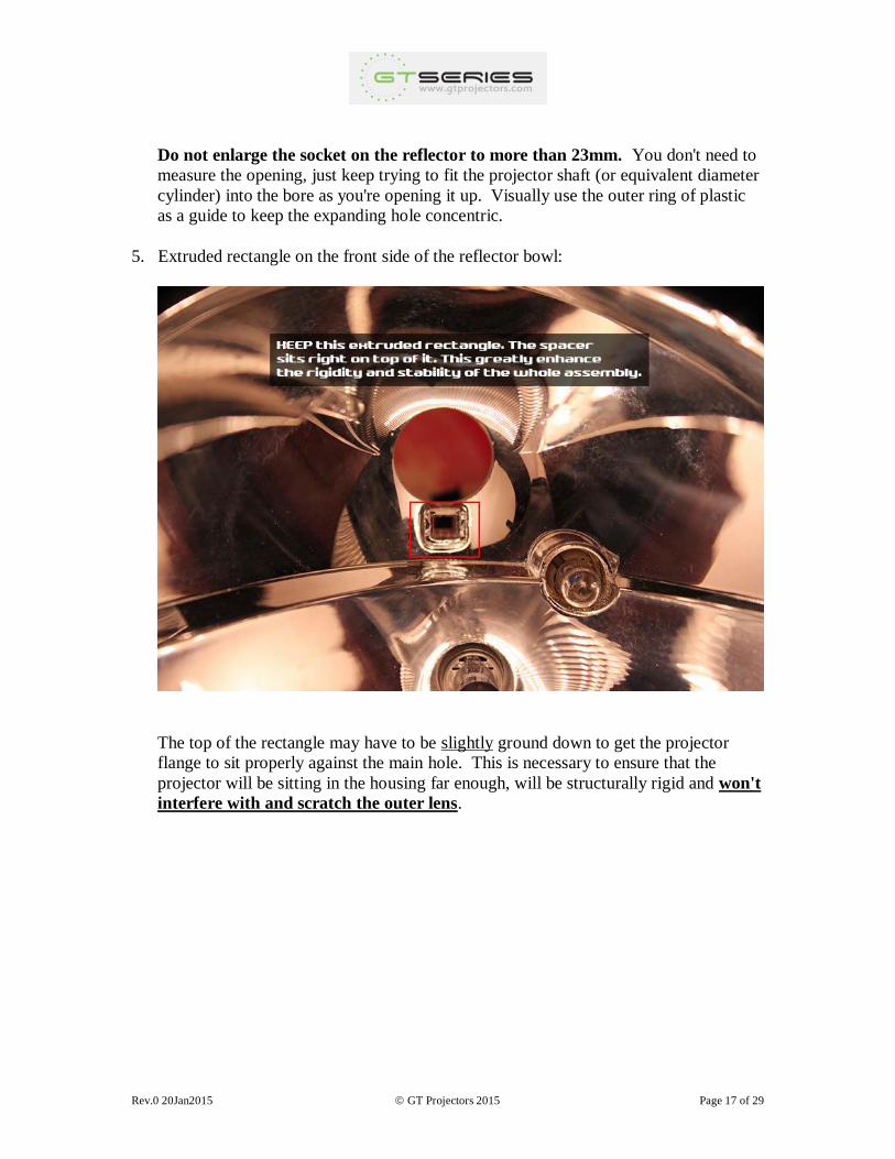
5. Extruded rectangle on the front side of the reflector bowl:
The top of the rectangle may have to be slightly ground down to get the projector
flange to sit properly against the main hole. This is necessary to ensure that the
projector will be sitting in the housing far enough, will be structurally rigid and won't
interfere with and scratch the outer lens.
Rev.0 20Jan2015 GT Projectors 2015 Page 18 of 29
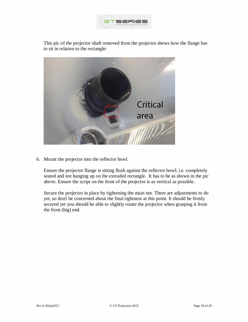
This pic of the projector shaft removed from the projector shows how the flange has
to sit in relation to the rectangle:
6. Mount the projector into the reflector bowl.
Ensure the projector flange is sitting flush against the reflector bowl; i.e. completely
seated and not hanging up on the extruded rectangle. It has to be as shown in the pic
above. Ensure the script on the front of the projector is as vertical as possible.
Secure the projector in place by tightening the main nut. There are adjustments to do
yet, so don't be concerned about the final tightness at this point. It should be firmly
secured yet you should be able to slightly rotate the projector when grasping it from
the front (big) end.
Rev.0 20Jan2015 GT Projectors 2015 Page 19 of 29
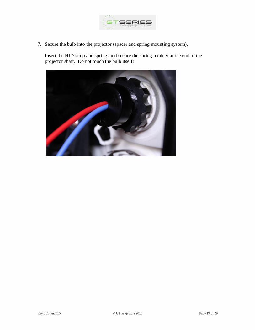
7. Secure the bulb into the projector (spacer and spring mounting system).
Insert the HID lamp and spring, and secure the spring retainer at the end of the
projector shaft. Do not touch the bulb itself!
Rev.0 20Jan2015 GT Projectors 2015 Page 20 of 29
4. INSTALLING THE BALLAST
The ballast can simply be squeezed inside the back of the headlight enclosure. The
manufacturer rates them over 120º C, and they have been tested in an enclosed, non-
ventilated space with a resulting maximum temperature of only 60º C.
However, this is a very tight fit, and the cleanest approach is to mount them outside the
headlight enclosure, fastening them to the outside of the back cover.
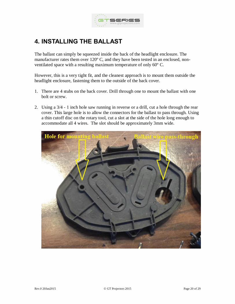
1. There are 4 stubs on the back cover. Drill through one to mount the ballast with one
bolt or screw.
2. Using a 3/4 - 1 inch hole saw running in reverse or a drill, cut a hole through the rear
cover. This large hole is to allow the connectors for the ballast to pass through. Using
a thin cutoff disc on the rotary tool, cut a slot at the side of the hole long enough to
accommodate all 4 wires. The slot should be approximately 3mm wide.
Rev.0 20Jan2015 GT Projectors 2015 Page 21 of 29
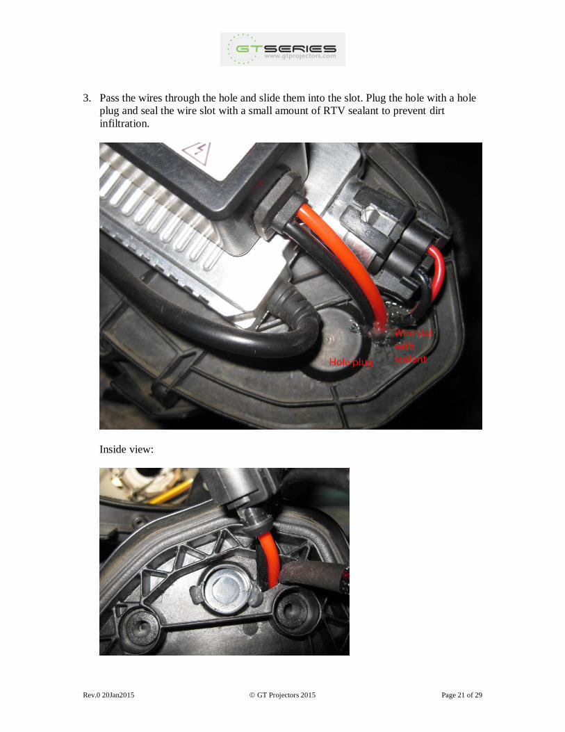
3. Pass the wires through the hole and slide them into the slot. Plug the hole with a hole
plug and seal the wire slot with a small amount of RTV sealant to prevent dirt
infiltration.
Inside view:
Rev.0 20Jan2015 GT Projectors 2015 Page 22 of 29
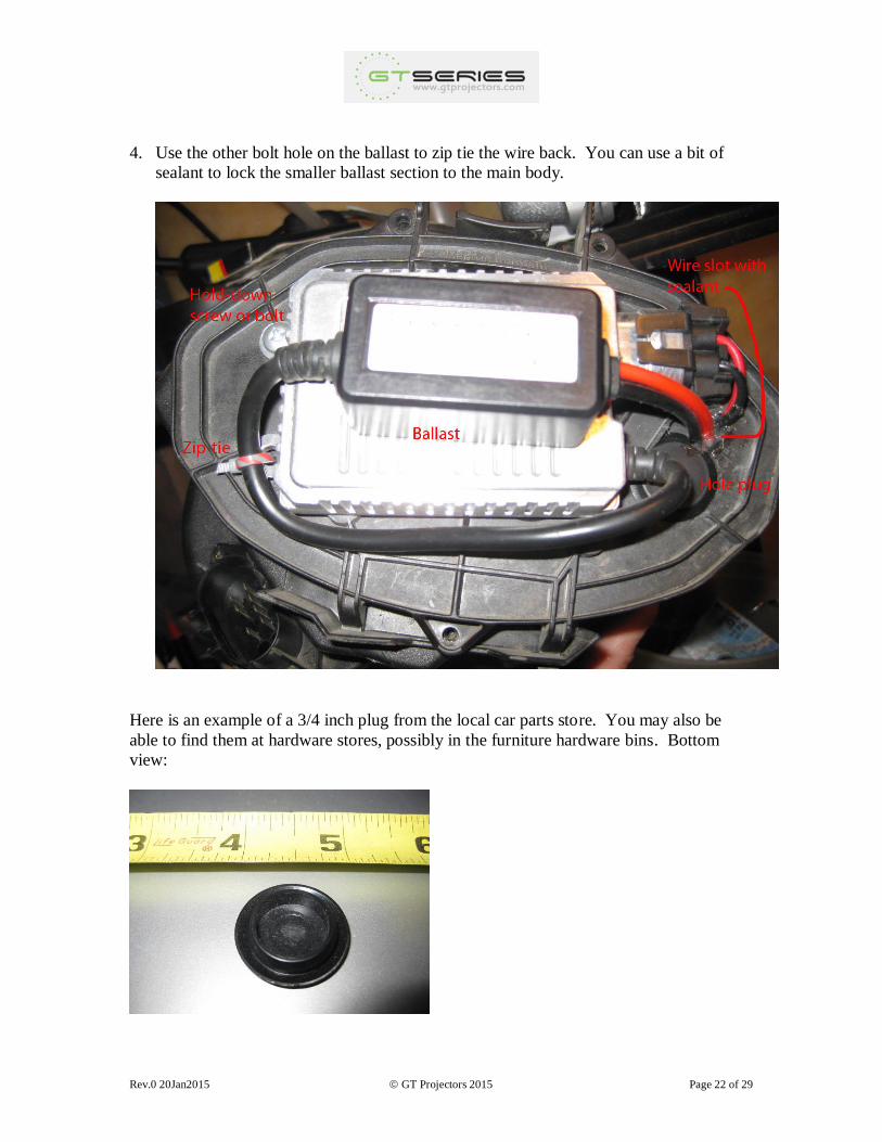
4. Use the other bolt hole on the ballast to zip tie the wire back. You can use a bit of
sealant to lock the smaller ballast section to the main body.
Here is an example of a 3/4 inch plug from the local car parts store. You may also be
able to find them at hardware stores, possibly in the furniture hardware bins. Bottom
view:
Rev.0 20Jan2015 GT Projectors 2015 Page 23 of 29
5. WIRING
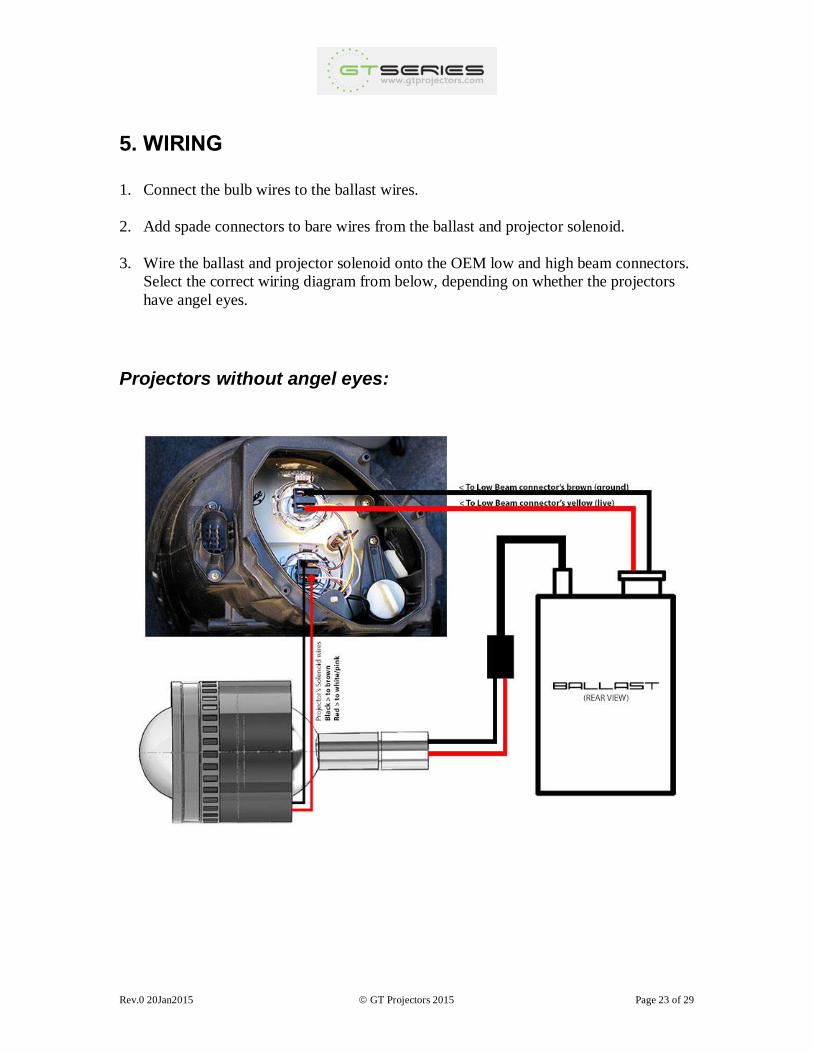
1. Connect the bulb wires to the ballast wires.
2. Add spade connectors to bare wires from the ballast and projector solenoid.
3. Wire the ballast and projector solenoid onto the OEM low and high beam connectors.
Select the correct wiring diagram from below, depending on whether the projectors
have angel eyes.
Projectors without angel eyes:
Rev.0 20Jan2015 GT Projectors 2015 Page 24 of 29
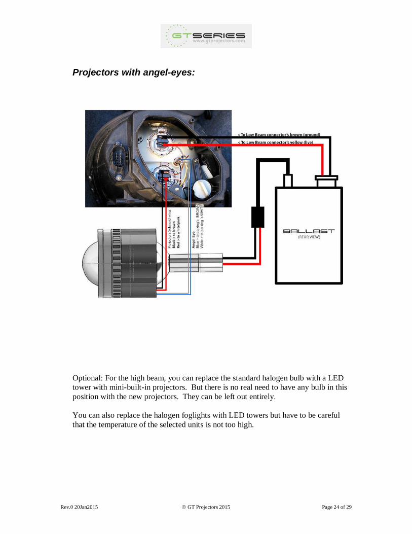
Projectors with angel-eyes:
Optional: For the high beam, you can replace the standard halogen bulb with a LED
tower with mini-built-in projectors. But there is no real need to have any bulb in this
position with the new projectors. They can be left out entirely.
You can also replace the halogen foglights with LED towers but have to be careful
that the temperature of the selected units is not too high.
Rev.0 20Jan2015 GT Projectors 2015 Page 25 of 29
6. TESTING
Before sealing the headlight, the system should be tested. This can be done using a 12V
DC source with a minimum current capacity of 10 amps (e.g. car battery, motorcycle
battery, or rectifier).
You need to ensure that (1) your ballasts are lighting up the bulbs and (2) your solenoid is
activating effectively.
Both can be tested by connecting the respective +/- wires onto 12 volts.
Another method of testing is to install the unsealed headlights into the car and proving
them there.
Rev.0 20Jan2015 GT Projectors 2015 Page 26 of 29
7. INITIAL LEVELING
Leveling the projector from side to side will ensure is that the projected cutoff line/beam
is horizontal. Two methods are available:
Method 1: With the headlight in the vehicle, and the car square to and aimed at a wall.
Method 2: Indoors, with the headlight leveled on a table and square to and aimed at a
wall. The indoor method provides less chance that the projector will move from it's
set position when removing the headlight from the vehicle. With the lens and inner
shroud removed, you can see a flat surface on the bottom of the headlight housing.
This is the vehicle's horizontal reference. With the headlight on the table, level that
flat bottom surface using a mini-spirit level. (If you do not have a mini-spirit level,
and only have the standard (long) model, simply place a perfectly square object on the
headlight's flat bottom surface and take the level reading from the top of that object.)
Once leveled, secure the headlight onto the table using tape.
Power up the ballast, keep your eyes on the wall, and turn the projector with one hand
until you are satisfied with the horizontal level of the cutoff line. When satisfied, tighten
the nut with a pair of long nose pliers.
Medium strength thread locker (Loctite Blue or equal) can be used to lock the socket nut
in two places: at the thread and where it contacts the reflector plastic. A drop in each
location is sufficient.
Rev.0 20Jan2015 GT Projectors 2015 Page 27 of 29
8. CLEANING AND SEALING
Lens cleaning: You've never touched the lens with your fingers. However when removing
the old silicon sealant, some particles and other dust may have found their way onto the
inner side of the lens. To clean it, simply blow compressed air on it or use a clean
microfiber cloth and HOT distilled water ONLY. Do not use tap water as this will leave
mineral residues on the lens. You'll want the water to evaporate quickly so do this in a
warm and clean environment (e.g. heated bathroom). Once done, place the lens back
inside a clean plastic bag until it is ready to be installed onto the headlight. A plain and
cheap garbage bag can be used (they are folded air-tight style by the manufacturer).
Next is to remove dust and particles from the headlight's housing, reflector and from the
inner shroud. Do a thorough job, as you don't want chunks of old sealant appearing in
your new lights!
Assuming the paint had time to cure (2-3 days), use the same microfiber and distilled
water to clean the headlight housing, insert reflector and cabling (everything!). Use a long
and slim plastic object to gently push the microfiber under the reflector and on its sides to
get rid of any dust hiding there while being careful not to scratch the new paint job. When
satisfied, again, keep everything in clean plastic bags to keep dust away until you are
ready to seal all this back together.
Sealing the headlight: fill the sealant compartment around the headlight housing to half
full with RTV silicon, and install the lens. Apply masking tape liberally to lock in place.
Check the sealant package for curing time. Forty-eight hours at room temperature should
be more than sufficient.
Optional: if the outside of the lens is showing its age, the yellowing from oxidation can
be cleaned up:
1) Wet sand with #1200 abrasive paper (carbide) (15 minutes per headlight)
2) Wet sand with #2000 (30 minutes per headlight). If #2000 isn't readily available, ask a
local jewelry shop where they get theirs.
3) Use a rotary pad/machine and buff with Maguire Headlight Restoration kit (30 - 45
minutes per headlight). Don't let the polycarbonate cool down when buffing them for the
whole period.
Overall it's a 2-1/2 hr job but once done you won't be able to see the difference between
an old unit and a new one.
Rev.0 20Jan2015 GT Projectors 2015 Page 28 of 29
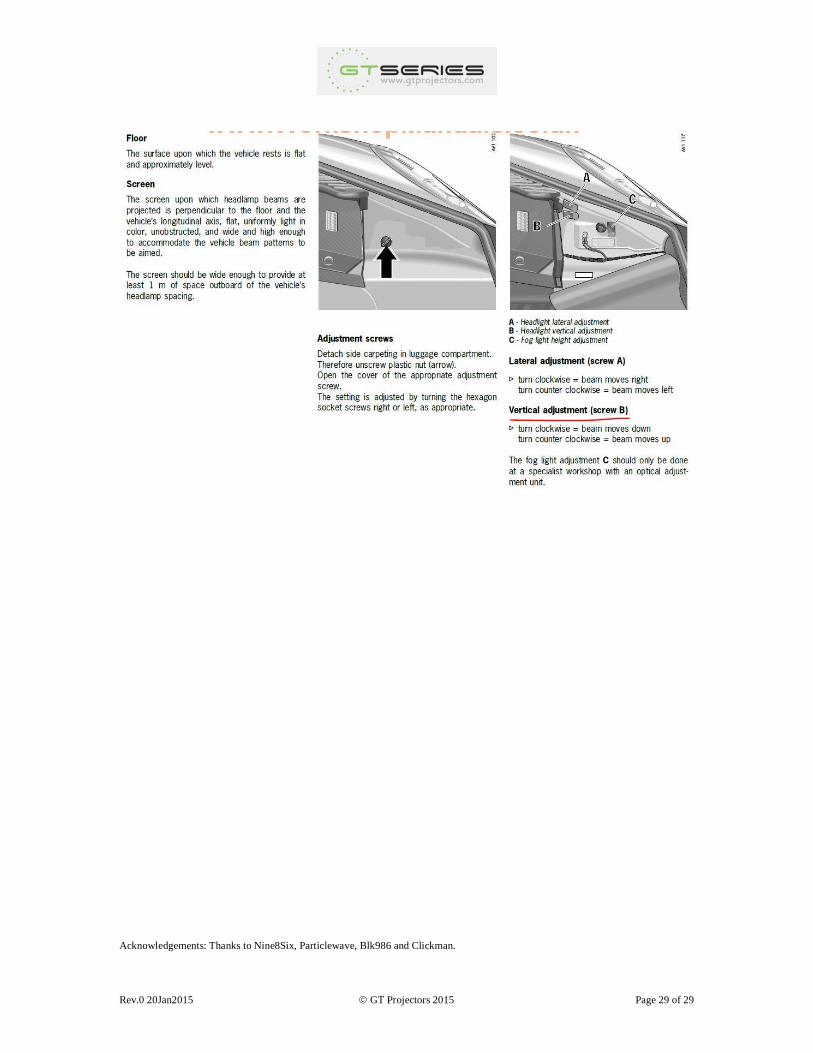
9. FINAL LEVELING
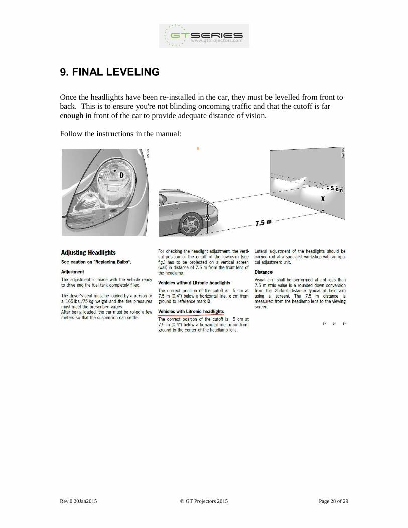
Once the headlights have been re-installed in the car, they must be levelled from front to
back. This is to ensure you're not blinding oncoming traffic and that the cutoff is far
enough in front of the car to provide adequate distance of vision.
Follow the instructions in the manual:
Rev.0 20Jan2015 GT Projectors 2015 Page 29 of 29
Acknowledgements: Thanks to Nine8Six, Particlewave, Blk986 and Clickman.