Embed Size (px)
Citation preview
Subsurface Exploration and Preliminary Geotechnical Engineering Report
PORT ANGELES DECANT FACILITY
Port Angeles, Washington
Prepared for
Herrera Environmental Consultants, Inc.
Project No. KE130594A January 30, 2015
January 30, 2015 Project No. KE140594A
Herrera Environmental Consultants, Inc. 2200 Sixth Avenue, Suite 1100 Seattle, Washington 98121
Attention: Ms. Rebecca Dugopolski
Subject: Subsurface Exploration and Preliminary Geotechnical Engineering Report Port Angeles Decant Facility 3501 West 18th Street Port Angeles, Washington
Dear Ms. Dugopolski:
We are pleased to present these copies of our report for the referenced project. This report summarizes the results of our subsurface exploration, geologic hazards, and geotechnical engineering studies, and offers recommendations for the design and development of the proposed project. Our report is preliminary since project plans were under development at the time this report was written. We should be allowed to review the recommendations presented in this report and modify them, if needed, once final project plans have been formulated.
We have enjoyed working with you on this study and are confident that the recommendations presented in this report will aid in the successful completion of your project. If you should have any questions, or if we can be of additional help to you, please do not hesitate to call.
Sincerely, ASSOCIATED EARTH SCIENCES, INC. Kirkland, Washington
______________________________ Matthew A. Miller, P.E. Principal Engineer
MM/ld - KE130594A2 - Projects\20130594\KE\WP
Kirkland Office | 911 Fifth Avenue | Kirkland, WA 98033 P | 425.827.7701 F| 425.827.5424 Everett Office | 2911 ½ Hewitt Avenue, Suite 2 | Everett, WA 98201 P | 425.259.0522 F | 425.252.3408
Tacoma Office | 1552 Commerce Street, Suite 102 | Tacoma, WA 98402 P | 253.722.2992 F | 253.722.2993 www.aesgeo.com
SUBSURFACE EXPLORATION AND PRELIMINARY GEOTECHNICAL ENGINEERING REPORT
PORT ANGELES DECANT FACILITY
Port Angeles, Washington
Prepared for: Herrera Environmental Consultants, Inc. 2200 Sixth Avenue, Suite 1100 Seattle, Washington 98121
Prepared by: Associated Earth Sciences, Inc.
911 5th Avenue Kirkland, Washington 98033
425-827-7701 Fax: 425-827-5424
January 30, 2015 Project No. KE130594A
Subsurface Exploration and Preliminary Port Angeles Decant Facility Geotechnical Engineering Report Port Angeles, Washington Project and Site Conditions
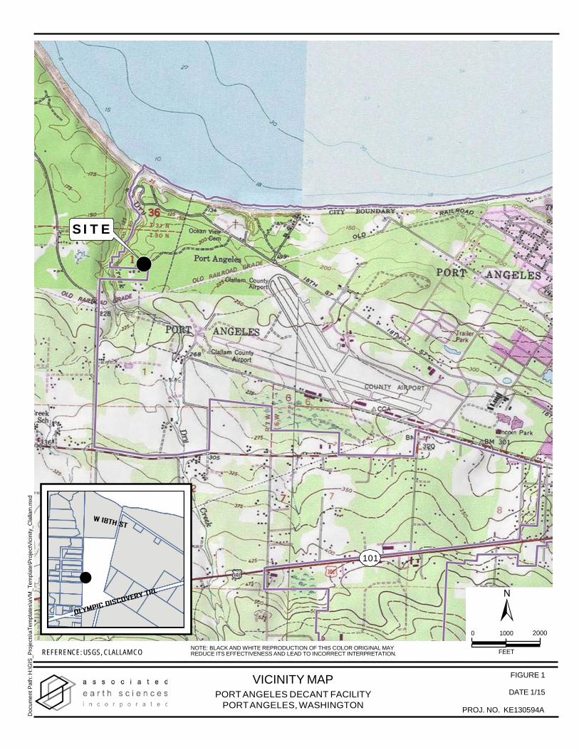
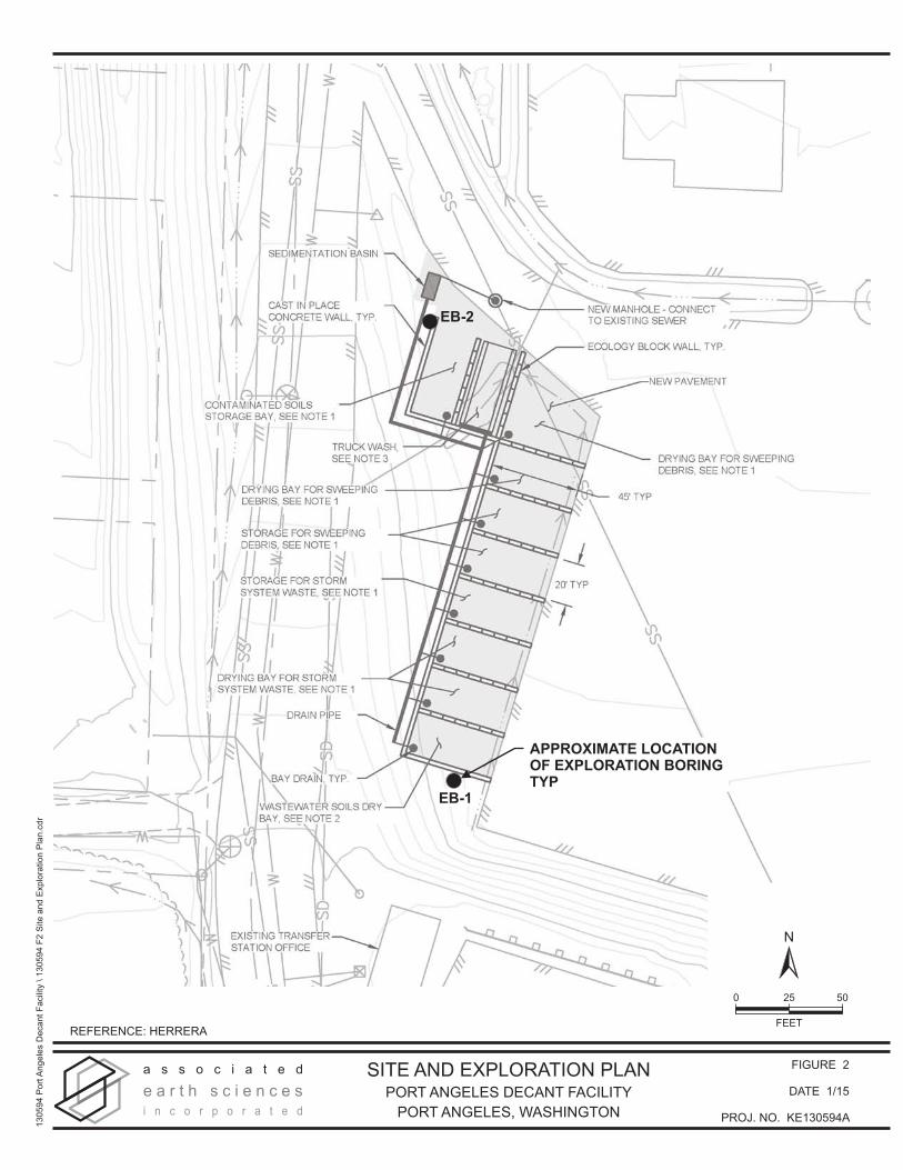
I. PROJECT AND SITE CONDITIONS 1.0 INTRODUCTION This report presents the results of our subsurface exploration and geotechnical engineering studies for the proposed improvements. The site location is shown on the “Vicinity Map,” Figure 1. The approximate locations of the exploration borings completed for this study are shown on the “Site and Exploration Plan,” Figure 2. Logs of the subsurface explorations completed for this study are included in the Appendix. 1.1 Purpose and Scope The purpose of this study was to provide geotechnical engineering design recommendations to be utilized in the design of the project. This study included a review of selected available geologic literature, advancing two hollow-stem auger soil borings, and performing geologic studies to assess the type, thickness, distribution, and physical properties of the subsurface sediments and shallow ground water. Geotechnical engineering studies were completed to establish recommendations for the type of suitable foundations, allowable foundation soil bearing pressure, anticipated foundation settlement, erosion control, and drainage considerations. This report summarizes our fieldwork and offers recommendations based on our present understanding of the project. We recommend that we be allowed to review the recommendations presented in this report and revise them, if needed, when a project design has been finalized. 1.2 Authorization Our study was accomplished in general accordance with our amended scope of work letter dated January 12, 2015. This report has been prepared for the exclusive use of Herrera Environmental Consultants, Inc. (Herrera) and its agents, for specific application to this project. Within the limitations of scope, schedule, and budget, our services have been performed in accordance with generally accepted geotechnical engineering and engineering geology practices in effect in this area at the time our report was prepared. No other warranty, express or implied, is made. Our observations, findings, and opinions are a means to identify and reduce the inherent risks to the owner. 2.0 PROJECT AND SITE DESCRIPTION The site is the current location of the City of Port Angeles’ existing regional transfer station, located at 3501 West 18th Street, in Port Angeles, Washington (Clallam County Parcel No: 073001220000). The property is approximately 32.85 acres in size and includes an existing
January 30, 2015 ASSOCIATED EARTH SCIENCES, INC. DMG/ld - KE130594A2 - Projects\20130594\KE\WP Page 1
Subsurface Exploration and Preliminary Port Angeles Decant Facility Geotechnical Engineering Report Port Angeles, Washington Project and Site Conditions garbage disposal transfer station, weigh scales, water treatment plant, compost facility, recycling center, moderate risk waste facility, a landfill, and other miscellaneous facilities. A paved road, the extension of West 18th Street, enters the property from the northeast and traverses the site to the southern extent. The property is bound by forests to the east and south, a forested ravine to the west, and the Strait of Juan de Fuca to the north. Site topography descends from south to north, and drops from about 235 feet above sea level (asl) to sea level. We understand that proposed improvements consist of the construction of a new decant facility near the southern end of the property for vactor and street sweeper waste. The proposed facility location is east of West 18th Street, northwest of the garbage disposal transfer station, and southwest of the moderate risk waste facility, in a small grassy field. The area is approximately 225 by 100 feet in dimension, covered in sod, and contains a small storm water pond. The area is mostly level along the eastern portion, with land gently rising in the west toward the road, and steeply rising approximately 15 feet along the south. A paved road and asphalt lot bound the area to the north and east. To our understanding, based on Figure B-1, “Decant Facility Preferred Alternative,” provided to Associated Earth Sciences, Inc. (AESI) by Herrera, the new decant facility will be located along the more level, eastern portion of the area described above. It will consist of nine drying/storage bays for sweeping debris, storm system waste, and contaminated waste. Additionally, one bay will be designated as a truck wash. The facility base will consist of new pavement and the bays will be separated by ecology block walls and/or cast-in-place concrete walls. Each of the drying/storage bays will be equipped with a bay drain connected to a single facility drain pipe and sedimentation basin, which is in turn connected to the existing on-site sewer line. Each bay is approximately 45 feet in length by 20 feet in width, and the entire facility will occupy a footprint of roughly 220 feet by 90 feet. Though not marked on the plans, it is our understanding that a metal canopy is planned to provide coverage of some of the bays. 3.0 SUBSURFACE EXPLORATION Our subsurface exploration completed for this project included advancing two hollow-stem auger soil borings. The conclusions and recommendations presented in this report are based on the explorations completed for this study. The locations and depths of the explorations were completed within site and budget constraints. 3.1 Exploration Borings The exploration borings were completed on the property on January 22, 2015, using a trailer-mounted drill rig advancing a 4.25-inch, inside-diameter, hollow-stem auger. During the drilling process, samples were obtained at 2.5- or 5-foot intervals. The borings were continuously
January 30, 2015 ASSOCIATED EARTH SCIENCES, INC. DMG/ld - KE130594A2 - Projects\20130594\KE\WP Page 2
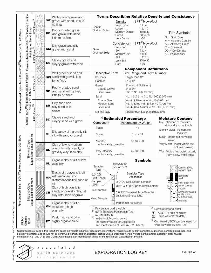
Subsurface Exploration and Preliminary Port Angeles Decant Facility Geotechnical Engineering Report Port Angeles, Washington Project and Site Conditions observed and logged by a geotechnical engineer from our firm. The exploration logs presented in the Appendix are based on the field logs, drilling action, and inspection of the samples secured. Disturbed but representative samples were obtained by using the Standard Penetration Test (SPT) procedure in accordance with American Society for Testing and Materials (ASTM):D 1586. This test and sampling method consists of driving a standard 2-inch, outside-diameter, split-barrel sampler a distance of 18 inches into the soil with a 140-pound hammer free-falling a distance of 30 inches. The number of blows for each 6-inch interval is recorded, and the number of blows required to drive the sampler the final 12 inches is known as the Standard Penetration Resistance (“N”) or blow count. If a total of 50 blows are recorded at or before the end of one 6-inch interval, the blow count is recorded as the number of blows for the corresponding number of inches of penetration. The resistance, or N-value, provides a measure of the relative density of granular soils or the relative consistency of cohesive soils. These values are plotted on the attached boring logs. The samples obtained from the split-barrel sampler were classified in the field and representative portions placed in watertight containers. The samples were then transported to our laboratory for further visual classification and geotechnical laboratory testing, as necessary. 4.0 SUBSURFACE CONDITIONS Subsurface conditions at the project site were inferred from the field explorations accomplished for this study, visual reconnaissance of the site, and review of selected applicable geologic literature. Because of the nature of exploratory work below ground, interpolation of subsurface conditions between field explorations is necessary. It should be noted that differing subsurface conditions may sometimes be present due to the random nature of deposition and the alteration of topography by past grading and/or filling. The nature and extent of any variations between the field explorations may not become fully evident until construction. In particular, historical aerial imagery from google earth indicates that the proposed location for the new decant facility has been stripped of a significant amount of earth (greater than 10 feet) in the early- to mid-2000s to prepare for the garbage transfer station. 4.1 Stratigraphy Sod/Topsoil A thin layer of sod and topsoil was encountered at ground surface in both explorations and extended to about 2 inches below ground surface (bgs). Due to its loose nature and high organic content, the existing sod/topsoil is not suitable for foundation support and should be stripped from subgrade areas prior to construction.
January 30, 2015 ASSOCIATED EARTH SCIENCES, INC. DMG/ld - KE130594A2 - Projects\20130594\KE\WP Page 3
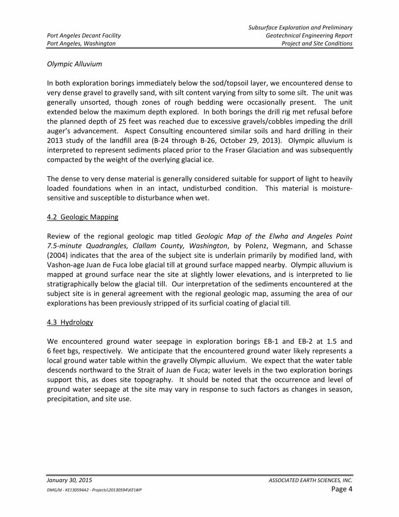
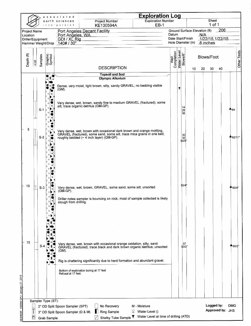
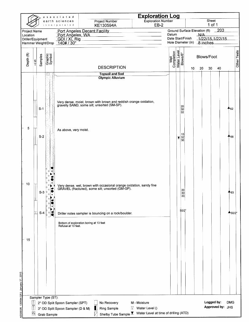
Subsurface Exploration and Preliminary Port Angeles Decant Facility Geotechnical Engineering Report Port Angeles, Washington Project and Site Conditions Olympic Alluvium In both exploration borings immediately below the sod/topsoil layer, we encountered dense to very dense gravel to gravelly sand, with silt content varying from silty to some silt. The unit was generally unsorted, though zones of rough bedding were occasionally present. The unit extended below the maximum depth explored. In both borings the drill rig met refusal before the planned depth of 25 feet was reached due to excessive gravels/cobbles impeding the drill auger’s advancement. Aspect Consulting encountered similar soils and hard drilling in their 2013 study of the landfill area (B-24 through B-26, October 29, 2013). Olympic alluvium is interpreted to represent sediments placed prior to the Fraser Glaciation and was subsequently compacted by the weight of the overlying glacial ice. The dense to very dense material is generally considered suitable for support of light to heavily loaded foundations when in an intact, undisturbed condition. This material is moisture-sensitive and susceptible to disturbance when wet. 4.2 Geologic Mapping Review of the regional geologic map titled Geologic Map of the Elwha and Angeles Point 7.5-minute Quadrangles, Clallam County, Washington, by Polenz, Wegmann, and Schasse (2004) indicates that the area of the subject site is underlain primarily by modified land, with Vashon-age Juan de Fuca lobe glacial till at ground surface mapped nearby. Olympic alluvium is mapped at ground surface near the site at slightly lower elevations, and is interpreted to lie stratigraphically below the glacial till. Our interpretation of the sediments encountered at the subject site is in general agreement with the regional geologic map, assuming the area of our explorations has been previously stripped of its surficial coating of glacial till. 4.3 Hydrology We encountered ground water seepage in exploration borings EB-1 and EB-2 at 1.5 and 6 feet bgs, respectively. We anticipate that the encountered ground water likely represents a local ground water table within the gravelly Olympic alluvium. We expect that the water table descends northward to the Strait of Juan de Fuca; water levels in the two exploration borings support this, as does site topography. It should be noted that the occurrence and level of ground water seepage at the site may vary in response to such factors as changes in season, precipitation, and site use.
January 30, 2015 ASSOCIATED EARTH SCIENCES, INC. DMG/ld - KE130594A2 - Projects\20130594\KE\WP Page 4
Subsurface Exploration and Preliminary Port Angeles Decant Facility Geotechnical Engineering Report Port Angeles, Washington Preliminary Design Recommendations
II. PRELIMINARY DESIGN RECOMMENDATIONS 5.0 INTRODUCTION Our explorations indicate that, from a geotechnical standpoint, the parcel is suitable for the proposed improvements provided the recommendations contained herein are properly followed. The subject site is underlain predominantly by dense to very dense native sediments which are suitable for foundation support. Existing fill, if encountered, is not suitable for support of new foundations, and warrants remedial preparation if occurring below the planned improvements. Ground water was measured at roughly 1.5 to 6 feet bgs at the locations of exploration borings EB-1 and EB-2, respectively. Therefore, if the planned sedimentation vault or new utilities extend below the ground water table, the contractor should be prepared to dewater any deep excavations (including the utility excavations), as needed. Also, walls/structures below the ground water table must be designed for combined soil and hydrostatic pressures and for buoyant/uplift forces, discussed in Section 10.2 of this report. 6.0 SITE PREPARATION 6.1 Clearing and Stripping Existing buried utilities, vegetation, topsoil, and any other deleterious materials should be removed where they are located below planned construction areas. Existing buried utilities that are to remain in use after construction of the facility may remain in place but should be protected during construction. All disturbed soils should be removed to expose underlying, undisturbed, native sediments and replaced with structural fill, as needed. All excavations below final grade made for clearing and grubbing activities should be backfilled, as needed, with structural fill. Erosion and surface water control should be established around the clearing limits to satisfy local requirements. Once clearing and grubbing activities have been completed, existing fill, if encountered, should be addressed. Although we do not anticipate the presence of fill in the proposed decant facility footprint, if encountered, we recommend that existing fill be removed from below areas of planned foundations to expose underlying, undisturbed native sediments, followed by restoration of the planned foundation grade with structural fill. Removal of existing fill should extend laterally beyond the structure footprint by a distance equal to the depth of overexcavation. For example, if existing fill is removed to a depth of 2 feet below a planned footing area, the excavation should also extend laterally 2 feet beyond the structure footprint in that area. Care should be taken not to disturb support soils of existing foundations. Support
January 30, 2015 ASSOCIATED EARTH SCIENCES, INC. DMG/ld - KE130594A2 - Projects\20130594\KE\WP Page 5
Subsurface Exploration and Preliminary Port Angeles Decant Facility Geotechnical Engineering Report Port Angeles, Washington Preliminary Design Recommendations soils should be considered those soils within a prism projected downward and outward from existing footings at inclinations of 1H:1V (Horizontal:Vertical). Where existing fill is removed and replaced with structural fill, conventional shallow foundations may be used for building support. The required depth of removal should be determined in the field based on actual conditions encountered during excavation. 6.2 Difficulty of Excavations Soil encountered near ground surface consisted of dense to very dense gravels and sandy gravels. Removal of soil to accommodate a below-grade foundation, new drains, and utilities will be somewhat difficult and may require a backhoe or excavator with teeth attached to the bucket. 6.3 Site Drainage and Surface Water Control The site should be graded to prevent water from ponding in construction areas and/or flowing into excavations. Exposed grades should be crowned, sloped, and smooth drum-rolled at the end of each day to facilitate drainage. Accumulated water must be removed from subgrades and work areas immediately prior to performing further work in the area. Equipment access may be limited, and the amount of soil rendered unfit for use as structural fill may be greatly increased if drainage efforts are not accomplished in a timely sequence. If an effective drainage system is not utilized, project delays and increased costs could be incurred due to the greater quantities of wet and unsuitable fill, or poor access and unstable conditions. We anticipate that shallow ground water will be encountered in excavations completed during construction, particularly if construction progresses during the wet season. The contractor should be prepared to intercept any ground water seepage entering the excavations and route it to a suitable discharge location. 6.4 Subgrade Protection To the extent that it is possible, existing pavement should be used for construction of staging areas. If building construction will proceed during the winter, we recommend the use of a working surface of sand and gravel, crushed rock, or quarry spalls to protect exposed soils, particularly in areas supporting concentrated equipment traffic. In winter construction staging areas and areas that will be subjected to repeated heavy loads, such as those that occur during construction of masonry walls, a minimum thickness of 12 inches of quarry spalls or 18 inches of pit run sand and gravel is recommended. If subgrade conditions are soft and silty, a geotextile separation fabric, such as Mirafi 500X or approved equivalent, should be used between the subgrade and the new fill. For building pads where floor slabs and foundation construction will be completed in the winter, a similar working surface should be used, composed of at least 6 inches of pit run sand and gravel or crushed rock. Construction of
January 30, 2015 ASSOCIATED EARTH SCIENCES, INC. DMG/ld - KE130594A2 - Projects\20130594\KE\WP Page 6
Subsurface Exploration and Preliminary Port Angeles Decant Facility Geotechnical Engineering Report Port Angeles, Washington Preliminary Design Recommendations working surfaces from advancing fill pads could be used to avoid directly exposing the subgrade soils to vehicular traffic. Foundation subgrades may require protection from foot and equipment traffic and ponding of runoff during wet weather conditions. Typically, compacted crushed rock or a lean-mix concrete mat placed over a properly prepared subgrade provides adequate subgrade protection. Foundation concrete should be placed and excavations backfilled as soon as possible to protect the bearing surface. 6.5 Proof-Rolling and Subgrade Compaction Following the recommended clearing, site stripping, and planned excavation, the stripped subgrade within the large foundation areas should be proof-rolled with heavy, rubber-tired construction equipment, such as a fully loaded, tandem-axle dump truck. Proof-rolling should be performed prior to structural fill placement or foundation excavation. The proof-roll should be monitored by the geotechnical engineer so that any soft or yielding subgrade soils can be identified. Any soft/loose, yielding soils should be removed to a stable subgrade. The subgrade should then be scarified, adjusted in moisture content, and recompacted to the required density. Proof-rolling should only be attempted if soil moisture contents are at or near optimum moisture content. Proof-rolling of wet subgrades could result in further degradation. Low areas and excavations may then be raised to the planned finished grade with compacted structural fill. Subgrade preparation and selection, placement, and compaction of structural fill should be performed under engineering-controlled conditions in accordance with the project specifications. 6.6 Wet Weather Conditions If construction proceeds during an extended wet weather construction period and the moisture-sensitive site soils become wet, they will become unstable. Therefore, the bids for site grading operations should be based upon the time of year that construction will proceed. It is expected that in wet conditions additional soils may need to be removed and/or other stabilization methods used, such as a coarse crushed rock working mat to develop a stable condition if silty subgrade soils are disturbed in the presence of excess moisture. The severity of construction disturbance will be dependent, in part, on the precautions that are taken by the contractor to protect the moisture- and disturbance-sensitive site soils. If overexcavation is necessary, it should be confirmed through continuous observation and testing by a representative of our firm. 6.7 Temporary and Permanent Cut Slopes In our opinion, stable construction slopes should be the responsibility of the contractor and should be determined during construction. For estimating purposes, however, we anticipate
January 30, 2015 ASSOCIATED EARTH SCIENCES, INC. DMG/ld - KE130594A2 - Projects\20130594\KE\WP Page 7
Subsurface Exploration and Preliminary Port Angeles Decant Facility Geotechnical Engineering Report Port Angeles, Washington Preliminary Design Recommendations that temporary, unsupported cut slopes in the existing dense to very dense native soils can be made at a maximum slope of 1H:1V or flatter. As is typical with earthwork operations, some sloughing and raveling may occur, and cut slopes may have to be adjusted in the field. If ground water seepage is encountered in cut slopes, or if surface water is not routed away from temporary cut slope faces, flatter slopes will be required. In addition, WISHA/OSHA regulations should be followed at all times. Permanent cut and structural fill slopes that are not intended to be exposed to surface water should be designed at inclinations of 2H:1V or flatter. All permanent cut or fill slopes should be compacted to at least 95 percent of the modified Proctor maximum dry density, as determined by ASTM:D 1557, and the slopes should be protected from erosion by sheet plastic until vegetation cover can be established during favorable weather. 6.8 Erosion Control To mitigate and reduce the erosion hazard potential and off-site soil transport during and post construction, we recommend the following:
1. All storm water from impermeable surfaces should be directed into an approved storm water drainage system or temporary storage facilities and should never be allowed to flow over the proposed infiltration area.
2. To reduce the amount of soil transport, silt fences or straw waddles should be placed along the perimeter of the area to be disturbed.
3. Construction should proceed during the drier periods of the year, if possible, and
disturbed areas should be covered, paved, or revegetated as soon as possible. 4. Soils, if they are to be reused around the site, should be stored in such a manner as to
reduce erosion and prevent runoff. Protective measures may include, but are not necessarily limited to, covering with plastic sheeting or the use of straw waddles/silt fences.
7.0 STRUCTURAL FILL All references to structural fill in this report refer to subgrade preparation, fill type and placement, and compaction of materials, as discussed in this section. If a percentage of compaction is specified under another section of this report, the value given in that section should be used. After stripping, planned excavation, and any required overexcavation have been performed to the satisfaction of the geotechnical engineer, the upper 12 inches of exposed ground in areas to
January 30, 2015 ASSOCIATED EARTH SCIENCES, INC. DMG/ld - KE130594A2 - Projects\20130594\KE\WP Page 8
Subsurface Exploration and Preliminary Port Angeles Decant Facility Geotechnical Engineering Report Port Angeles, Washington Preliminary Design Recommendations receive fill should be recompacted to a firm and unyielding condition. If the subgrade contains silty soils and too much moisture, adequate recompaction may be difficult or impossible to obtain and should probably not be attempted. In lieu of recompaction, the area to receive fill should be blanketed with washed rock or quarry spalls to act as a capillary break between the new fill and the wet subgrade. Where the exposed ground remains soft and further overexcavation is impractical, placement of an engineering stabilization fabric may be necessary to prevent contamination of the free-draining layer by silt migration from below. After recompaction of the exposed ground is approved, or a free-draining rock course is laid, structural fill may be placed to attain desired grades. Structural fill is defined as non-organic soil, acceptable to the geotechnical engineer, placed in maximum 8-inch loose lifts, with each lift being compacted to 95 percent of the modified Proctor maximum density using ASTM:D 1557 as the standard. The contractor should note that any proposed fill soils must be evaluated by the geotechnical engineer prior to their use in fills. This would typically require that the engineer have a sample of the material 72 hours in advance to perform a Proctor test and determine its field compaction standard. Soils in which the amount of fine-grained material (smaller than the No. 200 sieve) is greater than approximately 5 percent (measured on the minus No. 4 sieve size) should be considered moisture-sensitive. Use of moisture-sensitive soil in structural fills should be limited to favorable dry weather conditions. The native soils present on-site contained variable amounts of silt and are considered moisture-sensitive. In addition, construction equipment traversing the site when the soils are wet can cause considerable disturbance. If fill is placed during wet weather or if proper compaction cannot be obtained, a select import material consisting of a clean, free-draining gravel and/or sand should be used. Free-draining fill consists of non-organic soil with the amount of fine-grained material limited to 5 percent by weight when measured on the minus No. 4 sieve fraction with at least 25 percent retained on the No. 4 sieve. A geotechnical engineer should inspect the stripped subgrade and be present during placement of structural fill to observe the work and perform a representative number of in-place density tests. In this way, the adequacy of the earthwork may be evaluated as filling progresses, and any problem areas may be corrected at that time. It is important to understand that taking random compaction tests on a part-time basis will not assure uniformity or acceptable performance of a fill. As such, we are available to aid in developing a suitable monitoring and testing program. 8.0 FOUNDATIONS For footings bearing directly on the dense to very dense natural sediments, or on structural fill placed over these materials, as described above, we recommend that an allowable foundation
January 30, 2015 ASSOCIATED EARTH SCIENCES, INC. DMG/ld - KE130594A2 - Projects\20130594\KE\WP Page 9
Subsurface Exploration and Preliminary Port Angeles Decant Facility Geotechnical Engineering Report Port Angeles, Washington Preliminary Design Recommendations soil bearing pressure of 3,000 pounds per square foot (psf) be utilized for design purposes, including both dead and live loads. An increase of one-third may be used for short-term wind or seismic loading. Higher foundation soil bearing pressures are possible for foundations supported entirely on undisturbed very dense natural sediments; however, we do not expect that higher bearing pressures will be needed. If higher foundation soil bearing pressures are needed, we should be allowed to offer situation-specific recommendations. Foundations should be buried at least 18 inches into the surrounding soil for frost protection. However, all footings must penetrate to the prescribed bearing stratum, and no footing should be founded in or above organic or loose soils. All footings should have a minimum width of 18 inches. It should be noted that the area bound by lines extending downward at 1H:1V from any footing must not intersect another footing or intersect a filled area that has not been compacted to at least 95 percent of ASTM:D 1557. In addition, a 1.5H:1V line extending down from any footing must not daylight because sloughing or raveling may eventually undermine the footing. Thus, footings should not be placed near the edge of steps or cuts in the bearing soils. Anticipated settlement of footings founded as described above should be on the order of ¾ inch or less. However, disturbed soil not removed from footing excavations prior to footing placement could result in increased settlements. All footing areas should be inspected by AESI prior to placing concrete to verify that the design bearing capacity of the soils has been attained and that construction conforms to the recommendations contained in this report. Such inspections may be required by the governing municipality. Perimeter footing drains should be provided, as discussed under the “Drainage Considerations” section of this report. 8.1 Drainage Considerations Canopy Foundations Foundations should be provided with foundation drains placed at the base of footing elevation. Drains should consist of rigid, perforated, PVC pipe surrounded by washed pea gravel. The drains should be constructed with sufficient gradient to allow gravity discharge away from the proposed structure. Roof and surface runoff should not discharge into the footing drain system, but should be handled by a separate, rigid, tightline drain. In planning, exterior grades adjacent to walls should be sloped downward away from the proposed structure to achieve surface drainage. Sedimentation Vault Drainage Perimeter footing drains should be provided for the proposed sedimentation vault structure, as discussed under the “Drainage Considerations” section of this report. Proposed plans indicate
January 30, 2015 ASSOCIATED EARTH SCIENCES, INC. DMG/ld - KE130594A2 - Projects\20130594\KE\WP Page 10
Subsurface Exploration and Preliminary Port Angeles Decant Facility Geotechnical Engineering Report Port Angeles, Washington Preliminary Design Recommendations that the sedimentation vault will be located near the location of boring EB-2. Water level in this boring was approximately 6 feet bgs at the time of drilling, January 22, 2015. Ground water level in this area may increase or decrease seasonally and is anticipated to respond to variations in precipitation. Where gravity drainage is not possible, the portion of the structure below the drain level must be designed for combined soil and hydrostatic/buoyant forces, as described in Section 10.2 of this report. 9.0 FLOOR SUPPORT Slab-on-grade floors are anticipated over dense to very dense native soils, or over structural fill placed as recommended in the “Site Preparation” and “Structural Fill” sections of this report. Slab design can assume a soil subgrade modulus of 200 pounds per cubic inch (pci) for slabs cast over the dense to very dense, natural sediments or a limited thickness of properly compacted structural fill placed over these materials. Slab-on-grade floors should be cast atop a minimum of 4 inches of washed pea gravel or washed crushed “chip” rock with less than 3 percent passing the U.S. No. 200 sieve to act as a capillary break. Where moisture migration through the slab is to be controlled, the floor should also be protected from dampness by covering the capillary break layer with an impervious moisture barrier at least 10 mils in thickness. 10.0 FOUNDATION WALLS All backfill behind foundation walls or around foundation units should be placed as per our recommendations for structural fill and as described in this section of the report. For drained conditions, horizontally backfilled walls, which are free to yield laterally at least 0.1 percent of their height, may be designed using an equivalent fluid equal to 35 pounds per cubic foot (pcf). Fully restrained, horizontally backfilled, rigid walls that cannot yield should be designed for an equivalent fluid of 50 pcf. Walls with sloping backfill up to a maximum gradient of 2H:1V should be designed using an equivalent fluid of 55 pcf for yielding conditions or 75 pcf for fully restrained conditions. If parking areas are adjacent to walls, a surcharge equivalent to 2 feet of soil should be added to the wall height in determining lateral design forces. Undrained walls/structures, such as the submerged portions of the proposed vault walls, must be designed for combined soil and hydrostatic pressures (80 pcf for yielding walls, 90 pcf for unyielding walls with horizontal backfill), the abovementioned traffic surcharge, and for buoyant/uplift forces, described below. As required by the 2012 International Building Code (IBC), retaining wall design should include a seismic surcharge pressure in addition to the equivalent fluid pressures presented above. Considering the site soils and the recommended wall backfill materials, we recommend a
January 30, 2015 ASSOCIATED EARTH SCIENCES, INC. DMG/ld - KE130594A2 - Projects\20130594\KE\WP Page 11

Subsurface Exploration and Preliminary Port Angeles Decant Facility Geotechnical Engineering Report Port Angeles, Washington Preliminary Design Recommendations seismic surcharge pressure of 10H and 13H psf, where H is the wall height in feet for the “active” and “at-rest” loading conditions, respectively. The seismic surcharge should be modeled as a rectangular distribution with the resultant applied at the mid-point of the walls. The lateral pressures presented above are based on the conditions of a uniform backfill consisting of excavated on-site soils, or imported structural fill compacted to 90 percent of ASTM:D 1557. A higher degree of compaction is not recommended, as this will increase the pressure acting on the walls. A lower compaction may result in settlement of the slab-on-grade or other structures supported above the walls. Thus, the compaction level is critical and must be tested by our firm during placement. Surcharges from adjacent footings or heavy construction equipment must be added to the above values. Perimeter footing drains should be provided for all retaining walls, as discussed under the “Drainage Considerations” section of this report. For walls designed for drained conditions, it is imperative that proper drainage be provided so that hydrostatic pressures do not develop against the walls. This would involve installation of a minimum, 1-foot-wide blanket drain to within 1 foot of finish grade for the full wall height using imported, washed gravel against the walls. A prefabricated drainage mat is not a suitable substitute for the gravel blanket drain unless all backfill against the wall is free-draining. 10.1 Passive Resistance and Friction Factors Lateral loads can be resisted by friction between the foundation and the native soils or supporting structural fill soils, and by passive earth pressure acting on the buried portions of the foundations. The foundations must be backfilled with structural fill and compacted to at least 95 percent of the maximum dry density to achieve the passive resistance provided below. We recommend the following allowable design parameters:
• Passive equivalent fluid = 300 pcf • Coefficient of friction = 0.30
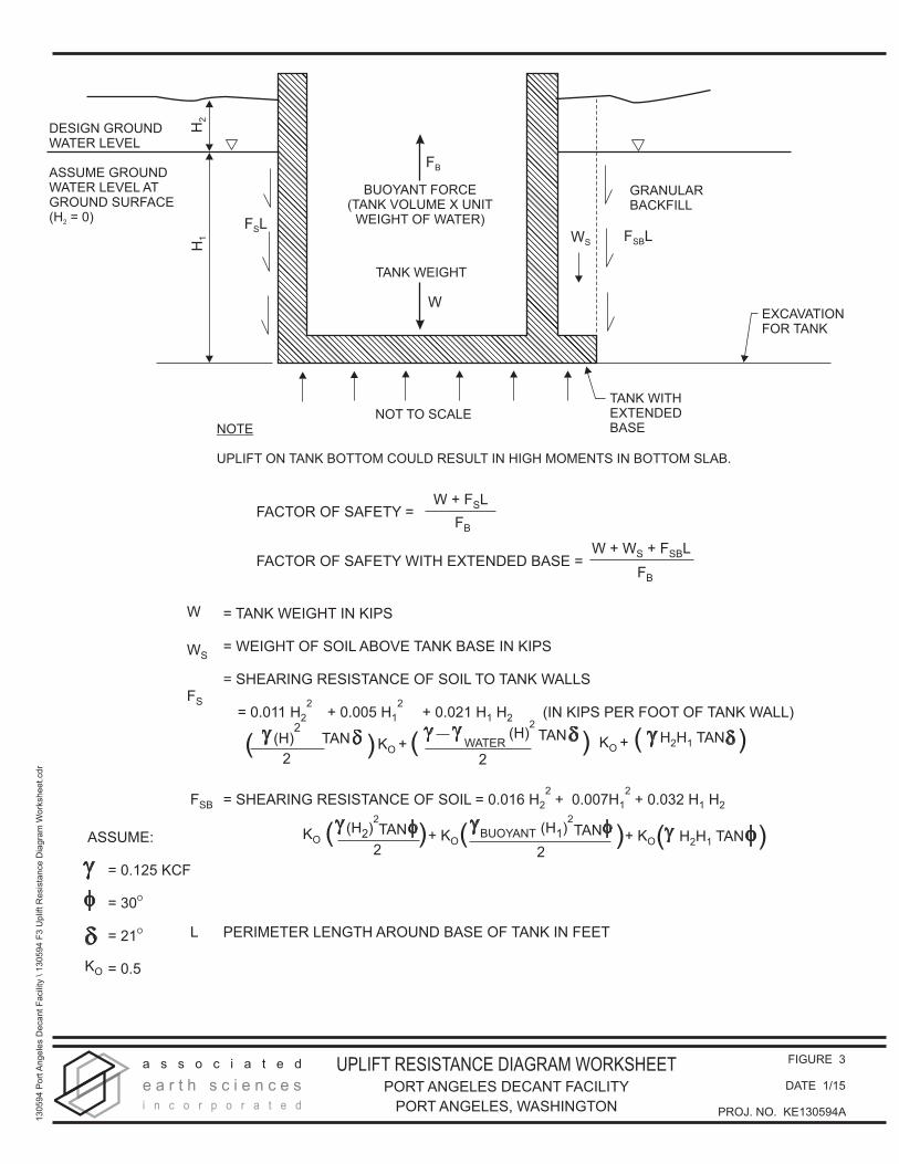
10.2 Buoyant/Uplift Forces Although the ground water level at the area of EB-2 was approximately 6 feet bgs at the time our exploration was performed, the ground water levels in this area can be higher during other times in the year, particularly during the typically wetter winter months. The ground water level in EB-1, for example, was 1.5 feet bgs. Therefore, if a vault extending roughly 10 feet bgs is planned, it should be designed to resist buoyant forces. Figure 3 provides a diagram and worksheet for the calculation of uplift forces and resistance. For preliminary planning purposes, we recommend that a conservative approach be used for the vault structure. This approach assumes a ground water table at the ground surface for the incorporation of buoyancy/uplift forces in design. Typical design features to account for buoyant forces are
January 30, 2015 ASSOCIATED EARTH SCIENCES, INC. DMG/ld - KE130594A2 - Projects\20130594\KE\WP Page 12
Subsurface Exploration and Preliminary Port Angeles Decant Facility Geotechnical Engineering Report Port Angeles, Washington Preliminary Design Recommendations thickened slabs, base slab extensions, increased footing widths, increased overlying soil weight, or an engineered anchoring system. As shown on Figure 3, the dry unit weight of the Olympic alluvium in the existing site stratigraphy may be assumed to be 125 pcf. 11.0 PAVEMENT RECOMMENDATIONS Pavement areas should be prepared in accordance with the “Site Preparation” section of this report. If the stripped native soil or existing fill pavement subgrade can be compacted to 95 percent of ASTM:D 1557 and is firm and unyielding, no additional overexcavation is required. Soft or yielding areas should be overexcavated to provide a suitable subgrade and backfilled with structural fill. The pavement sections included in this report section are for the decant facility footprint, and are not applicable to right-of-way improvements. At this time we are not aware of any planned right-of-way improvements; however, if any new paving of public streets is required, we should be allowed to offer situation-specific recommendations. The exposed ground should be recompacted to 95 percent of ASTM:D 1557. If required, structural fill may then be placed to achieve desired subbase grades. Upon completion of the recompaction and structural fill, the proposed pavement section consisting of 4 inches of asphalt concrete pavement (ACP) underlain by 2 inches of 5/8-inch crushed surfacing top course and 4 inches of 1¼-inch crushed surfacing base course is the recommended minimum in areas subjected to heavy loads, such as from loaded trucks. The crushed rock courses must be compacted to 95 percent of the maximum density, as determined by ASTM:D 1557. All paving materials should meet gradation criteria contained in the current Washington State Department of Transportation (WSDOT) Standard Specifications. Depending on construction staging and desired performance, the crushed base course material may be substituted with asphalt treated base (ATB) beneath the final asphalt surfacing. The substitution of ATB should be as follows: 4 inches of crushed rock can be substituted with 3 inches of ATB, and 6 inches of crushed rock may be substituted with 4 inches of ATB. ATB should be placed over a native or structural fill subgrade compacted to a minimum of 95 percent relative density, and a 1½- to 2-inch thickness of crushed rock to act as a working surface. If ATB is used for construction access and staging areas, some rutting and disturbance of the ATB surface should be expected. The general contractor should remove affected areas and replace them with properly compacted ATB prior to final surfacing.
January 30, 2015 ASSOCIATED EARTH SCIENCES, INC. DMG/ld - KE130594A2 - Projects\20130594\KE\WP Page 13
Subsurface Exploration and Preliminary Port Angeles Decant Facility Geotechnical Engineering Report Port Angeles, Washington Preliminary Design Recommendations
12.0 PROJECT DESIGN AND CONSTRUCTION MONITORING
Our report is preliminary since project plans were not finalized at the time this report was written. We recommend that AESI perform a geotechnical review of the plans prior to final design completion. In this way, we can confirm that our earthwork and foundation recommendations have been properly interpreted and implemented in the design.
We are also available to provide geotechnical engineering and monitoring services during construction. The integrity of the foundation system depends on proper site preparation and construction procedures. In addition, engineering decisions may have to be made in the field in the event that variations in subsurface conditions become apparent. Construction monitoring services are not part of this current scope of work. If these services are desired, please let us know, and we will prepare a cost proposal.
We have enjoyed working with you on this study and are confident that these recommendations will aid in the successful completion of your project. If you should have any questions or require further assistance, please do not hesitate to call.
Sincerely, ASSOCIATED EARTH SCIENCES, INC. Kirkland, Washington
______________________________ Danika M. Globokar E.I.T., G.I.T. Matthew A. Miller, P.E. Senior Staff Engineer Principal Engineer
Attachments: Figure 1: Vicinity Map Figure 2: Site and Exploration Plan Figure 3: Uplift Resistance Diagram Worksheet Appendix: Exploration Logs
January 30, 2015 ASSOCIATED EARTH SCIENCES, INC.DMG/ld - KE130594A2 - Projects\20130594\KE\WP Page 14
Copyright:© 2013 National Geographic Society, i-cubed
Doc
umen
t Pat
h: H
:\GIS
_Pro
ject
s\aT
empl
ates
\aVM
_Tem
plat
e\Pr
ojec
tVic
inity
_Cla
llam
.mxd
SITE
!(
REFERENCE: USGS, CLALLAM CO
101
NOTE: BLACK AND WHITE REPRODUCTION OF THIS COLOR ORIGINAL MAY REDUCE ITS EFFECTIVENESS AND LEAD TO INCORRECT INTERPRETATION.
± 0 1000
FEET
2000
VICINITY MAP PORT ANGELES DECANT FACILITY
PORT ANGELES, WASHINGTON
FIGURE 1
DATE 1/15
PROJ. NO. KE130594A
!
a s s o c i a t e d
e a r t h s c i e n c e si n c o r p o r a t e d
FEET
25 500
N
FIGURE 2
DATE 1/15
PROJ. NO. KE130594A
SITE AND EXPLORATION PLANPORT ANGELES DECANT FACILITY
PORT ANGELES, WASHINGTON
13
05
94
Po
rtA
ng
ele
s D
eca
nt
Fa
cili
ty \
13
05
94
F2
Site
an
d E
xp
lora
tio
n P
lan
.cd
r
REFERENCE: HERRERA
EB-1
EB-2
APPROXIMATE LOCATION
OF EXPLORATION BORING
TYP
H2
H1
GRANULARBACKFILL
EXCAVATIONFOR TANK
TANK WITHEXTENDEDBASE
NOT TO SCALE
DESIGN GROUNDWATER LEVEL
ASSUME GROUNDWATER LEVEL ATGROUND SURFACE(H = 0)2 F LS
F LSBWS
FB
W
BUOYANT FORCE(TANK VOLUME X UNIT
WEIGHT OF WATER)
TANK WEIGHT
NOTE
UPLIFT ON TANK BOTTOM COULD RESULT IN HIGH MOMENTS IN BOTTOM SLAB.
FACTOR OF SAFETY =
FACTOR OF SAFETY WITH EXTENDED BASE =
W + F LS
FB
W + W + F LS SB
FB
ASSUME:
= 0.125 KCF
= 30O
= 21O
= 0.5KO
= TANK WEIGHT IN KIPS
= WEIGHT OF SOIL ABOVE TANK BASE IN KIPS
= SHEARING RESISTANCE OF SOIL TO TANK WALLS
= SHEARING RESISTANCE OF SOIL = 0.016 H + 0.007H + 0.032 H H2 1 1 2
2 2
PERIMETER LENGTH AROUND BASE OF TANK IN FEET
W
WS
FS
FSB
L
= 0.011 H2
2+ 0.005 H1
2+ 0.021 H H1 2 (IN KIPS PER FOOT OF TANK WALL)
K +OK +O
(H)2
2
TAN( )TAN( )WATER
2
(H)2
( )H H TAN2 1
KOTAN( )
2
(H )2
2
+ KO + KO
2
TAN( )BUOYANT (H )1
2
H H TAN2 1( )
a s s o c i a t e d
e a r t h s c i e n c e si n c o r p o r a t e d
FIGURE 3
DATE 1/15
PROJ. NO. KE130594A
UPLIFT RESISTANCE DIAGRAM WORKSHEET
PORT ANGELES DECANT FACILITY
PORT ANGELES, WASHINGTON
13
05
94
Po
rtA
ng
ele
s D
eca
nt
Fa
cili
ty \
13
05
94
F3
Up
lift
Re
sis
tan
ce
Dia
gra
m W
ork
sh
ee
t.cd
r

APPENDIX