Embed Size (px)
Citation preview
Washington University in St. Louis Washington University in St. Louis
Washington University Open Scholarship Washington University Open Scholarship
Washington University / UMSL Mechanical Engineering Design Project JME 4110 Mechanical Engineering & Materials Science
Spring 5-9-2018
Portable Shopping Cart Portable Shopping Cart
Stacy Otzenberger Washington University in St. Louis, [email protected]
Heath Daniel McClung Washington University in St. Louis, [email protected]
Follow this and additional works at: https://openscholarship.wustl.edu/jme410
Recommended Citation Recommended Citation Otzenberger, Stacy and McClung, Heath Daniel, "Portable Shopping Cart" (2018). Washington University / UMSL Mechanical Engineering Design Project JME 4110. 15. https://openscholarship.wustl.edu/jme410/15
This Final Report is brought to you for free and open access by the Mechanical Engineering & Materials Science at Washington University Open Scholarship. It has been accepted for inclusion in Washington University / UMSL Mechanical Engineering Design Project JME 4110 by an authorized administrator of Washington University Open Scholarship. For more information, please contact [email protected].
This document captures the complete design-to-prototype process for a portable shopping system. The
following report outlines the decision making processes dictated by consumer interviews, safety
regulations, and manufacturing constraints. All pertinent photographs, CAD drawings, and video links
are included in this document.
JME 4110
Mechanical Engineering
Design Project
Portable Shopping Cart
Stacy Otzenberger
Heath McClung
1
TABLE OF CONTENTS
List of Figures ..................................................................................................................................... 3
List of Tables ...................................................................................................................................... 4
1 Introduction ..................................................................................................................................... 5
1.1 Value proposition / project suggestion .................................................................................... 5
1.2 List of team members .............................................................................................................. 5
2 Background Information Study ....................................................................................................... 5
2.1 Desgin Brief ............................................................................................................................ 5
2.2 Background summary ............................................................................................................. 5
3 Concept Design and Specification .................................................................................................. 9
3.1 User Needs and Metrics .......................................................................................................... 9
3.1.1 Record of the user needs interview ................................................................................. 9
3.1.2 List of identified metrics ............................................................................................... 11
3.1.3 Table/list of quantified needs equations ........................................................................ 11
3.2 Concept drawings .................................................................................................................. 12
3.3 A concept selection process. ................................................................................................. 17
3.3.1 Concept scoring (not screening) ................................................................................... 17
3.3.2 Preliminary analysis of each concept’s physical feasibility .......................................... 18
3.3.3 Final summary statement .............................................................................................. 20
3.4 Proposed performance measures for the design .................................................................... 20
3.5 Revision of specifications after concept selection ................................................................ 20
4 Embodiment and fabrication plan ................................................................................................. 22
4.1 Embodiment/Assembly drawing ........................................................................................... 22
4.2 Parts List ............................................................................................................................... 23
4.3 Draft detail drawings for each manufactured part ................................................................. 24
4.4 Description of the design rationale ....................................................................................... 25
5 Engineering analysis ..................................................................................................................... 29
5.1 Engineering analysis proposal .............................................................................................. 29
5.1.1 Signed engineering analysis contract ............................................................................ 29
5.2 Engineering analysis results .................................................................................................. 30
5.2.1 Motivation ..................................................................................................................... 30
5.2.2 Summary statement of analysis done ............................................................................ 30
5.2.3 Methodology ................................................................................................................. 30
5.2.4 Results ........................................................................................................................... 30
2
5.2.5 Significance ................................................................................................................... 32
6 Risk Assessment ........................................................................................................................... 33
6.1 Risk Identification ................................................................................................................. 33
6.2 Risk Analysis ........................................................................................................................ 34
6.3 Risk Prioritization ................................................................................................................. 35
7 Codes and Standards ..................................................................................................................... 37
7.1 Identification ......................................................................................................................... 37
7.2 Justification ........................................................................................................................... 37
7.3 Design Constraints ................................................................................................................ 38
7.3.1 Safety ............................................................................................................................ 38
7.3.2 Legal .............................................................................................................................. 38
7.4 Significance ........................................................................................................................... 38
8 Working prototype ........................................................................................................................ 39
8.1 prototype Photos ................................................................................................................... 39
8.2 Working Prototype Video ..................................................................................................... 40
8.3 Prototype components ........................................................................................................... 41
9 Design documentation................................................................................................................... 41
9.1 Final Drawings and Documentation ..................................................................................... 43
9.1.1 Engineering Drawings ................................................................................................... 43
9.2 Final Presentation .................................................................................................................. 43
10 Appendix A - Parts List/Bill of Materials ................................................................................. 43
11 Appendix B – Complete List of Engineering Drawings ........................................................... 43
12 Annotated Bibliography ............................................................................................................ 44
3
LIST OF FIGURES
Figure 1: IDEO Shopping Cart. .............................................................................................................. 6
Figure 2: Lotus Trolley Bags. ................................................................................................................. 7
Figure 3: Drawing For Stair Climbing Wheel ........................................................................................ 8
Figure 4: Concept #1 ............................................................................................................................. 12
Figure 5: Concept #2 ............................................................................................................................. 13
Figure 6: Concept #3 ............................................................................................................................. 14
Figure 7: Concept #4a ........................................................................................................................... 15
Figure 8: Concept #4b ........................................................................................................................... 16
Figure 9: Main Frame Components ...................................................................................................... 22
Figure 10: Linkage Sizing Hand Calculations ...................................................................................... 31
Figure 11: Bottom Frame FEA ............................................................................................................. 32
Figure 12: Risk Assessment Process ..................................................................................................... 33
Figure 13: Prototype in Opened Position .............................................................................................. 39
Figure 14: Prototype in Folded Position ............................................................................................... 40
Figure 15: Hinge and Wheel Assembly ................................................................................................ 41
Figure 16: Shelf Bracket ....................................................................................................................... 41
Figure 17: Carrying Handle .................................................................................................................. 42
Figure 18: Bottom End Closed Position ............................................................................................... 42
4
LIST OF TABLES
Table 1: User Needs Interview................................................................................................................ 9
Table 2: Initial Needs Table for Portable Shopping System. ................................................................ 10
Table 3: Identified Metrics .................................................................................................................... 11
Table 4: Quantified Needs Matrix ........................................................................................................ 11
Table 5: Concept #1 Metrics Scoring ................................................................................................... 17
Table 6: Concept #2 Metrics Scoring ................................................................................................... 17
Table 7: Concept #3 Metrics Scoring ................................................................................................... 18
Table 8: Concept #4 Metrics Scoring ................................................................................................... 18
Table 9: Revised Identified Metrics ...................................................................................................... 20
Table 10: Revised Concept #4 Metrics Scoring .................................................................................... 21
Table 11: Bill of Materials .................................................................................................................... 23
5
1 INTRODUCTION
1.1 VALUE PROPOSITION / PROJECT SUGGESTION
The shopping cart design has remained unchanged for decades despite a significant change
to consumer behaviors. Retailers like Aldis, Sam’s Club, and Costco have moved away from
the traditional use of plastic shopping bags, fueled by consumer demands for more sustainable
and environmentally-friendly practices. A new design for a shopping that embraces reusable
bags can make trips to the store much easier and efficient by streamlining the checkout process
while providing a more organized approach to storing purchases.
1.2 LIST OF TEAM MEMBERS
Heath McClung
Stacy Otzenberger
2 BACKGROUND INFORMATION STUDY
2.1 DESIGN BRIEF
Design a mobile modular shopping system that the user owns and has the ability to go from
the user’s vehicle to the store and back to the vehicle with ease, or more specifically the least
amount of physical exertion by the user. The design utilizes versatile and reusable shopping
bags and/or baskets and assists in organizing groceries in a more strategic pattern. We intend to
use an existing bag/basket that will fit into a fabricated cart system. This cart system will be
lightweight, collapsible, and easy to store in vehicle. The entire system should be able to hold
at least 100 pounds of groceries, fit into a trunk size of 20 cubic feet. The system will be
designed to expedite the whole shopping process, eliminating the need to obtain and return a
store owned cart to the corral or store. System should require no more than two minutes to
assemble or disassemble. To minimize cost, risk, and size, a child restrain will not be included.
2.2 BACKGROUND SUMMARY
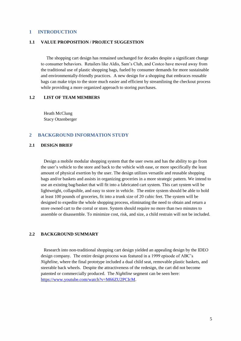
Research into non-traditional shopping cart design yielded an appealing design by the IDEO
design company. The entire design process was featured in a 1999 episode of ABC’s
Nightline, where the final prototype included a dual child seat, removable plastic baskets, and
steerable back wheels. Despite the attractiveness of the redesign, the cart did not become
patented or commercially produced. The Nightline segment can be seen here:
https://www.youtube.com/watch?v=M66ZU2PCIcM.
6
Figure 1 - IDEO Shopping Cart
7
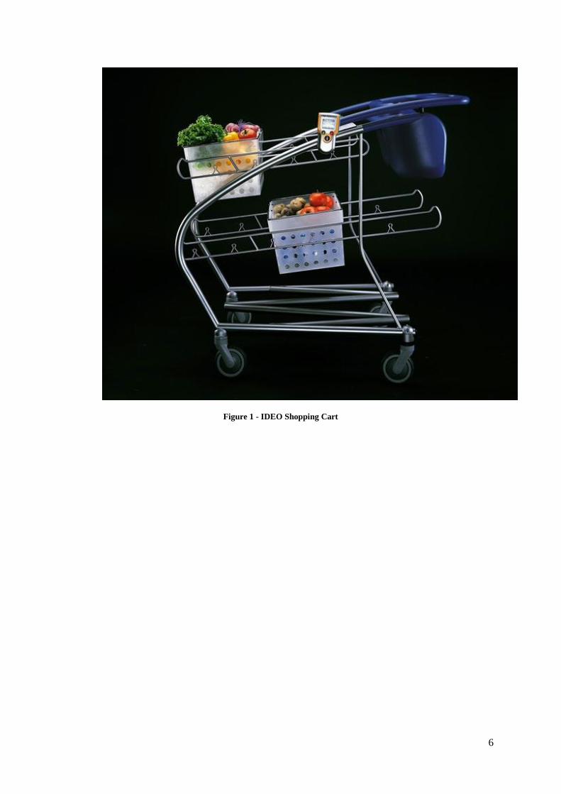
Although not an entire shopping cart design, another existing product addressing the design
problem is the Lotus Trolley Bag. This reusable shopping bag can hang on a traditional
shopping cart as well as the eventual prototype of our design with some minor alterations.
Figure 2 - Lotus Trolley Bags
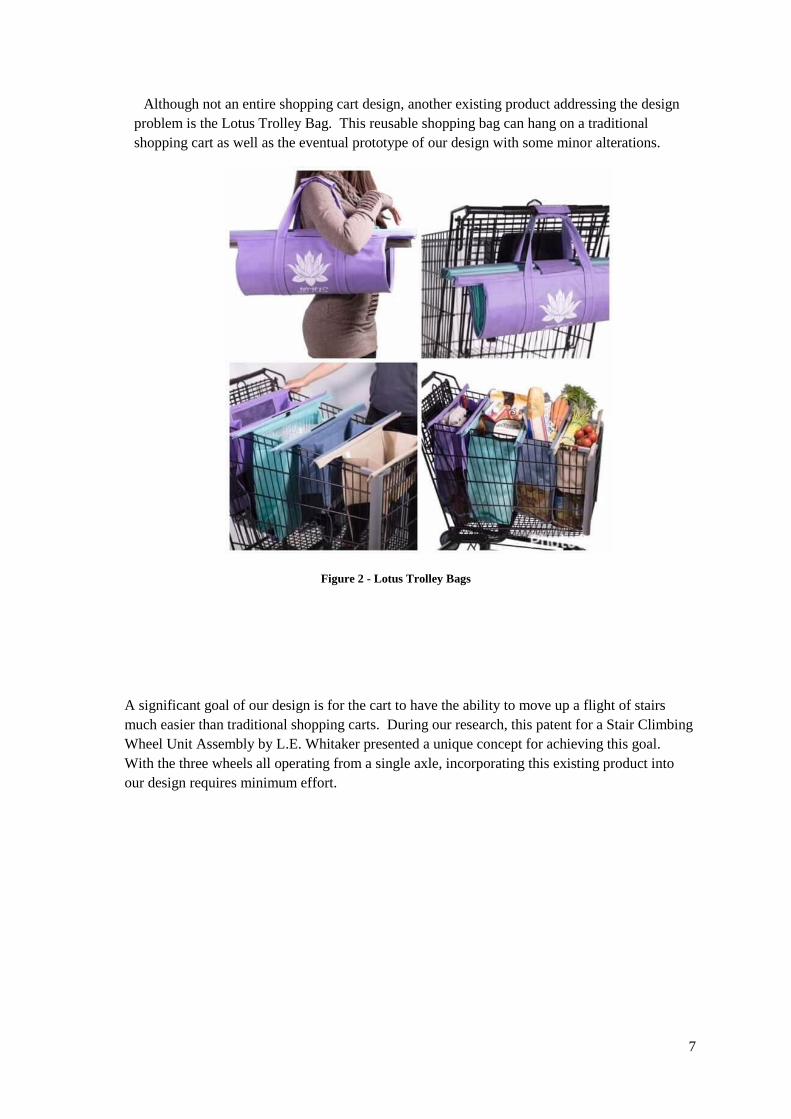
A significant goal of our design is for the cart to have the ability to move up a flight of stairs
much easier than traditional shopping carts. During our research, this patent for a Stair Climbing
Wheel Unit Assembly by L.E. Whitaker presented a unique concept for achieving this goal.
With the three wheels all operating from a single axle, incorporating this existing product into
our design requires minimum effort.
8
Figure 3 - Drawing for Stair Climbing Wheel
Lastly, the only related standard of safety for shopping carts is ASTM F2372-15 Standard
Consumer Safety Performance Specification for Shopping Carts:
“The ASTM standard also requires retailers to inspect and replace broken seat belts and to ensure that
every shopping cart remains in good working order. Also the standard suggests that the retailer provide
safety information and use safety posters to communicate safe behavior to consumers. Most retailers
provide shopping cart restraints on all of their carts The ASTM shopping cart standard is intended to cover
children who are 6 months to 4 years old and weigh 15 to 35 pounds. Among other things, the standard
requires that shopping carts with a child seating area have adjustable child restraint systems with child-
resistant buckles or closures. It also requires that each shopping cart include a warning label with
pictograms that includes specific safety messages, such as “ALWAYS buckle-up child in cart seat and
fasten securely.”
Given the implications of this safety standard, a child seat was purposefully not incorporated into
the goals of the design. Instead the focus became to create a device for individuals shopping
without children or those using public transportation.
9
3 CONCEPT DESIGN AND SPECIFICATION
3.1 USER NEEDS AND METRICS
3.1.1 Record of the user needs interview
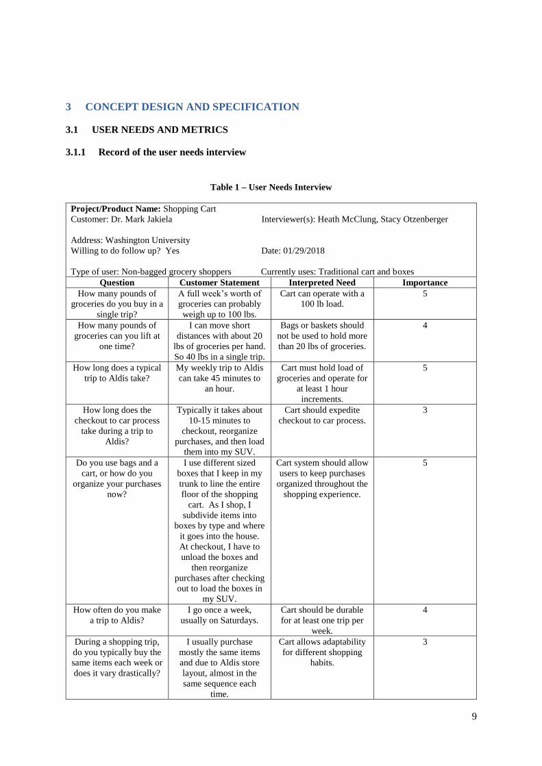
Table 1 – User Needs Interview
Project/Product Name: Shopping Cart
Customer: Dr. Mark Jakiela Interviewer(s): Heath McClung, Stacy Otzenberger
Address: Washington University
Willing to do follow up? Yes Date: 01/29/2018
Type of user: Non-bagged grocery shoppers Currently uses: Traditional cart and boxes
Question Customer Statement Interpreted Need Importance
How many pounds of
groceries do you buy in a
single trip?
A full week’s worth of
groceries can probably
weigh up to 100 lbs.
Cart can operate with a
100 lb load.
5
How many pounds of
groceries can you lift at
one time?
I can move short
distances with about 20
lbs of groceries per hand.
So 40 lbs in a single trip.
Bags or baskets should
not be used to hold more
than 20 lbs of groceries.
4
How long does a typical
trip to Aldis take?
My weekly trip to Aldis
can take 45 minutes to
an hour.
Cart must hold load of
groceries and operate for
at least 1 hour
increments.
5
How long does the
checkout to car process
take during a trip to
Aldis?
Typically it takes about
10-15 minutes to
checkout, reorganize
purchases, and then load
them into my SUV.
Cart should expedite
checkout to car process.
3
Do you use bags and a
cart, or how do you
organize your purchases
now?
I use different sized
boxes that I keep in my
trunk to line the entire
floor of the shopping
cart. As I shop, I
subdivide items into
boxes by type and where
it goes into the house.
At checkout, I have to
unload the boxes and
then reorganize
purchases after checking
out to load the boxes in
my SUV.
Cart system should allow
users to keep purchases
organized throughout the
shopping experience.
5
How often do you make
a trip to Aldis?
I go once a week,
usually on Saturdays.
Cart should be durable
for at least one trip per
week.
4
During a shopping trip,
do you typically buy the
same items each week or
does it vary drastically?
I usually purchase
mostly the same items
and due to Aldis store
layout, almost in the
same sequence each
time.
Cart allows adaptability
for different shopping
habits.
3
10
Do you want the cart to
help just at the store, or
at home as well?
If it could help me go up
a flight of stairs once I
get home, that would be
great. My kids
sometimes help me now,
but it takes several trips
up the stairs from the
garage to the kitchen to
unload groceries.
Cart can go up stairs
with a load of purchases.
4
How big do you expect
the cart to be?
I hope it can fit in the
trunk of my SUV with
groceries, especially if I
can use it once I get
home.
Cart must collapse and
fit into the trunk of a car.
5
How much would you
pay for a cart system that
addresses your needs?
I think I would pay
around $100-$150.
Cart costs less than $200. 3
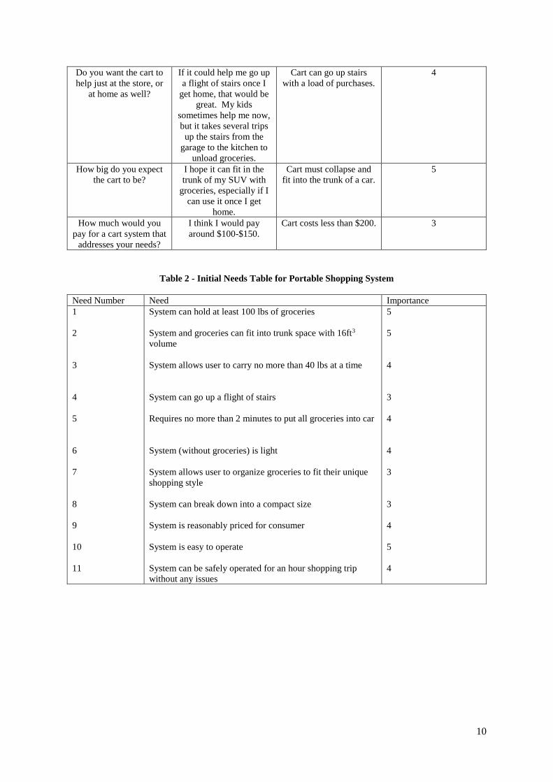
Table 2 - Initial Needs Table for Portable Shopping System
Need Number Need Importance
1
2
3
4
5
6
7
8
9
10
11
System can hold at least 100 lbs of groceries
System and groceries can fit into trunk space with 16ft3
volume
System allows user to carry no more than 40 lbs at a time
System can go up a flight of stairs
Requires no more than 2 minutes to put all groceries into car
System (without groceries) is light
System allows user to organize groceries to fit their unique
shopping style
System can break down into a compact size
System is reasonably priced for consumer
System is easy to operate
System can be safely operated for an hour shopping trip
without any issues
5
5
4
3
4
4
3
3
4
5
4
11
3.1.2 List of identified metrics
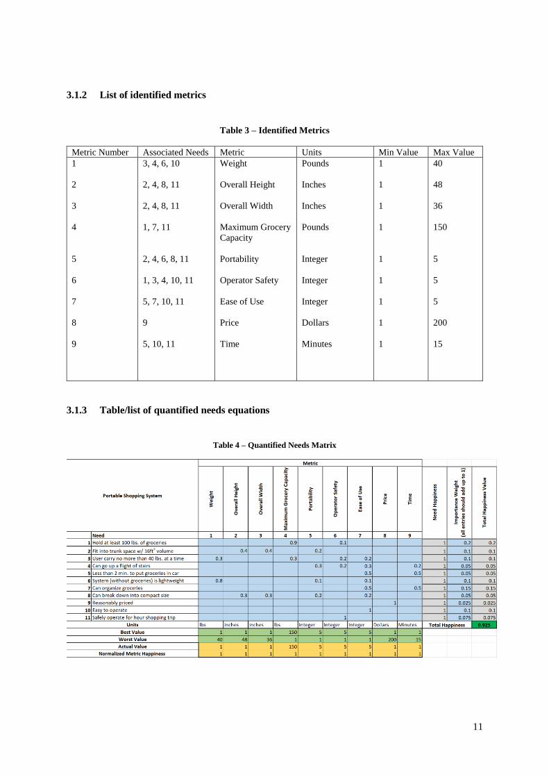
Table 3 – Identified Metrics
Metric Number Associated Needs Metric Units Min Value Max Value
1
2
3
4
5
6
7
8
9
3, 4, 6, 10
2, 4, 8, 11
2, 4, 8, 11
1, 7, 11
2, 4, 6, 8, 11
1, 3, 4, 10, 11
5, 7, 10, 11
9
5, 10, 11
Weight
Overall Height
Overall Width
Maximum Grocery
Capacity
Portability
Operator Safety
Ease of Use
Price
Time
Pounds
Inches
Inches
Pounds
Integer
Integer
Integer
Dollars
Minutes
1
1
1
1
1
1
1
1
1
40
48
36
150
5
5
5
200
15
3.1.3 Table/list of quantified needs equations
Table 4 – Quantified Needs Matrix
12
3.2 CONCEPT DRAWINGS
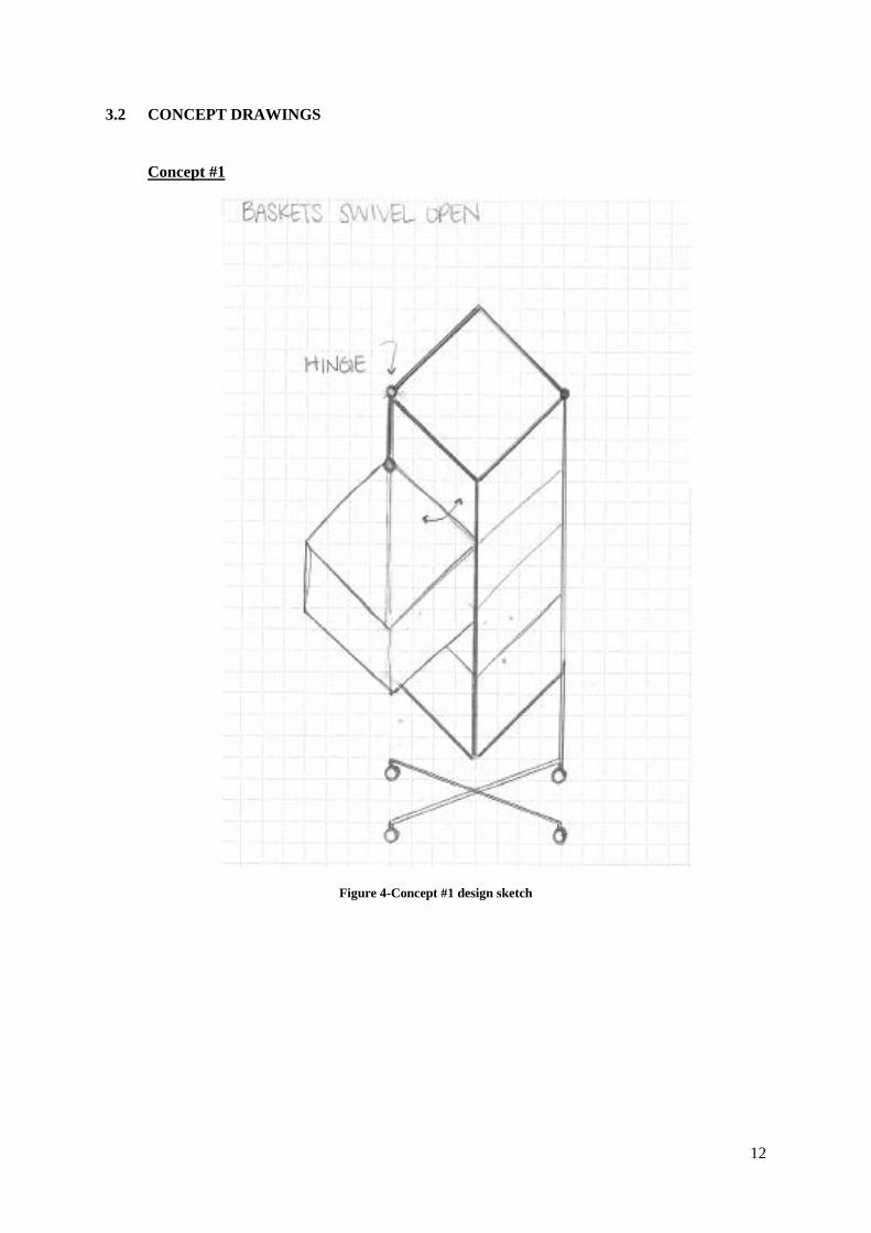
Concept #1
Figure 4-Concept #1 design sketch
13
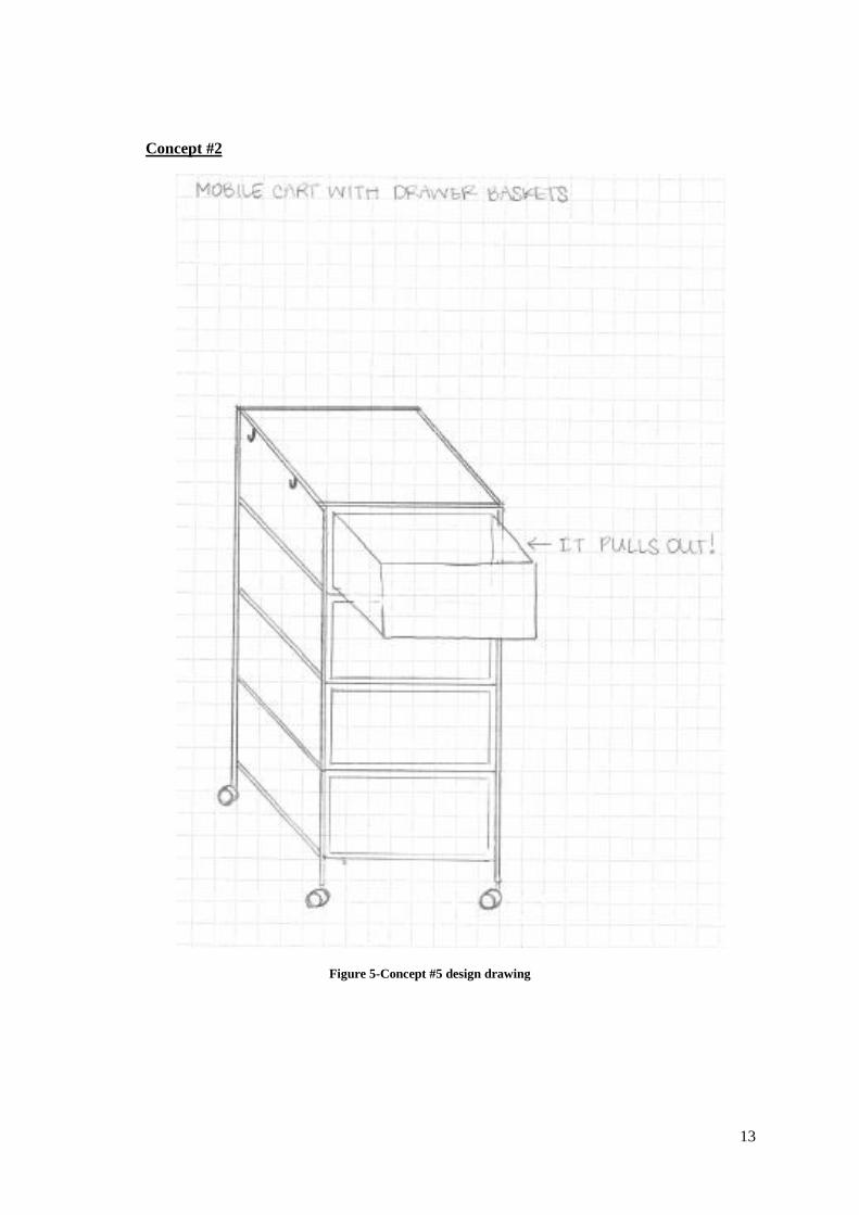
Concept #2
Figure 5-Concept #5 design drawing
14
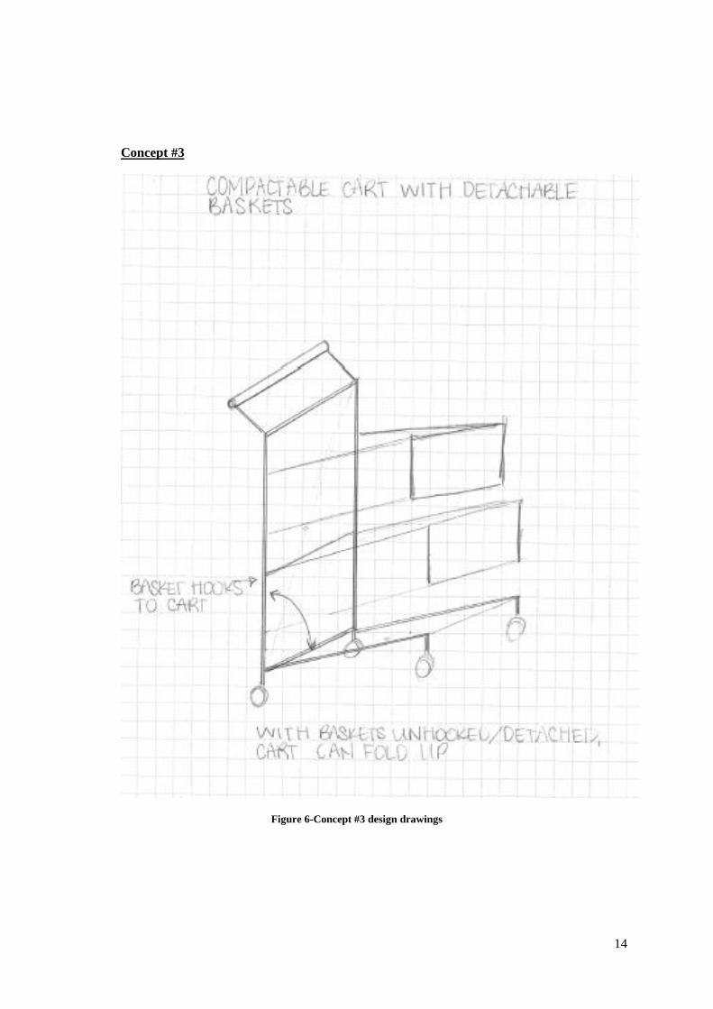
Concept #3
Figure 6-Concept #3 design drawings
15
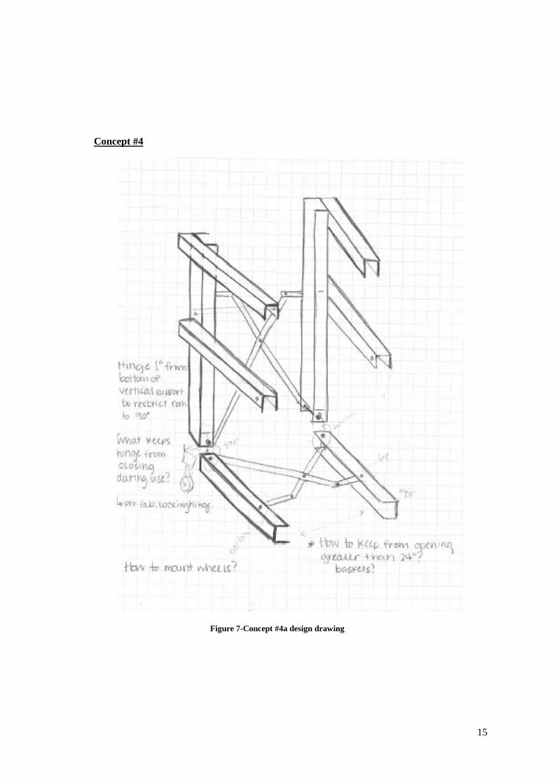
Concept #4
Figure 7-Concept #4a design drawing
16
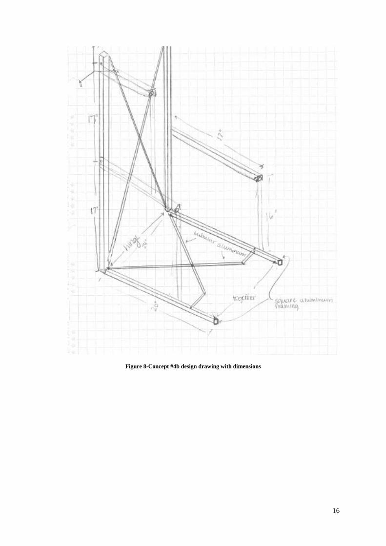
Figure 8-Concept #4b design drawing with dimensions
17
3.3 A CONCEPT SELECTION PROCESS.
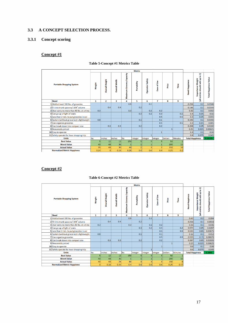
3.3.1 Concept scoring
Concept #1
Table 5-Concept #1 Metrics Table
Concept #2
Table 6-Concept #2 Metrics Table
18
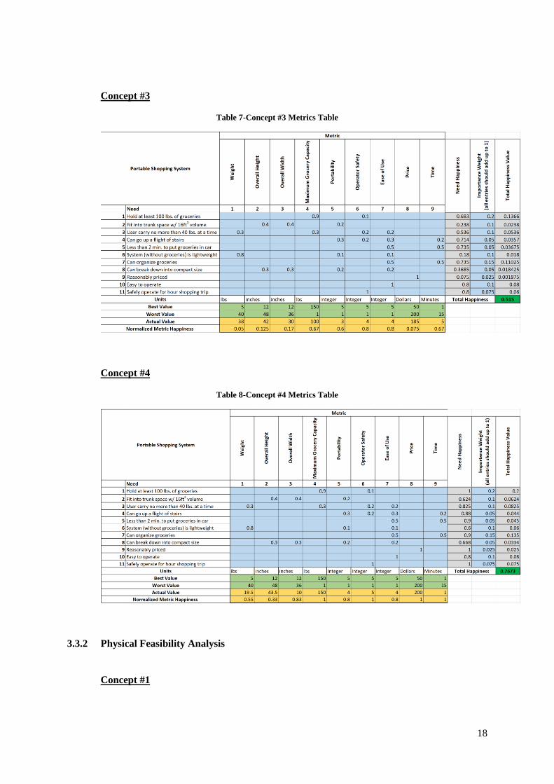
Concept #3
Table 7-Concept #3 Metrics Table
Concept #4
Table 8-Concept #4 Metrics Table
3.3.2 Physical Feasibility Analysis
Concept #1
19
Concept 1 consists of a set of four drawers attached to a rolling fixture. The drawers
swivel open using hinges attached to a single vertical support bar and are mounted to the
rolling frame by a vertical support bar on the opposite corner from the hinges. While the
design seems simple and easy to use, trying to design a relatively tall system of drawers able
to house different purchases is difficult. The overall height makes the cart easy to tip over,
especially in circumstances of rough terrain such as parking lots and tiled floors. Although
we envisioned the drawer system detaching from the cart to be placed into a vehicle, the
system does not collapse further and complicates transportation.
Concept #2
Concept 2 utilizes a similar system of four drawers, but operates differently than
Concept 1. The drawers pull out in the traditional fashion and are mounted to a metal frame
with four caster wheels. Although organization is maintained during shopping, the user must
still remove all items from the drawers during the check-out process and then re-organize
everything. While these drawer systems are easy to purchase pre-made, none have the ability
to carry 100 lbs worth of load. Additionally, the typical plastic caster wheels do not roll
smoothly under load either.
Concept #3
Concept 3 consists of a metal cart with baskets that hook to horizontal bars mounted
on the rear vertical frame. When the baskets are detached from the cart, the metal frame folds
in half, leaving a flat cart of equal width but substantially shorter. The cart has four caster
wheels similar to those found on a traditional shopping cart. The connection between the
basket and horizontal bar may prove difficult to design with the capacity to hold a significant
portion of the overall 100 lbs worth of groceries. The cantilever design requires a heavily
reinforced connection, but still may result in the cart tipping forward if the load is distributed
unevenly.
Concept #4
Concept 4 is the most feasible of all four concepts because it collapses to become
extremely portable. The cart consists of a vertical and horizontal assemblies made from
aluminum C-channel and articulating aluminum poles that allow the C-channel to move
together and apart. The two identical vertical and horizontal assemblies are attached by two
locking hinges. Collapsible shelving brackets mount to the vertical C-channels to allow for
reusable shopping bags to span across the brackets. The most difficult aspect to the design is
calculating the geometry of all articulating parts to maximize the ability to collapse and
expand.
20
3.3.3 Final summary statement
After considering the four concepts, user needs, user metrics, and feasibility of
designs, concept #4 provides the most potential in achieving desired outcomes. The concept
collapses to become the most portable and user-friendly of all the designs, allowing users to
store the cart in a vehicle’s trunk with shopping purchases. The entire cart uses two main
materials for the entire construction (aluminum C-channel, ½” aluminum pipe) which are
relatively cheap and easy to manipulate with common tools. This design provides an
opportunity to create a new practical shopping cart with the ability to adapt to user needs,
potentially attracting real consumers.
3.4 PROPOSED PERFORMANCE MEASURES FOR THE DESIGN
The overall goal of the project is to create a portable shopping cart system that
performs according to the needs of the user. With the selection of concept #4, we re-
examined the original specifications defined from our user needs interview and determined
the original metrics will suffice for our specific design. However, some alterations of the
specific maximum and minimum values for the metrics provide a better reference for a
successful or unsuccessful final product. By using strictly aluminum material for our frame,
the maximum overall weight was changed to 20 pounds, since the user indicated that is the
maximum weight normally carried in one hand. The price also changed to a more realistic
value since the cost of aluminum is higher due to the decreased weight and also recent shifts
in the market. The most important indications to the success of the design is the maximum
grocery capacity compared to the size of the cart in its folded-up state. Ease of use, shopping
time, and portability can vary more depending on the specific user and their familiarity of the
cart. These metrics can change as the user utilizes the cart more frequently.
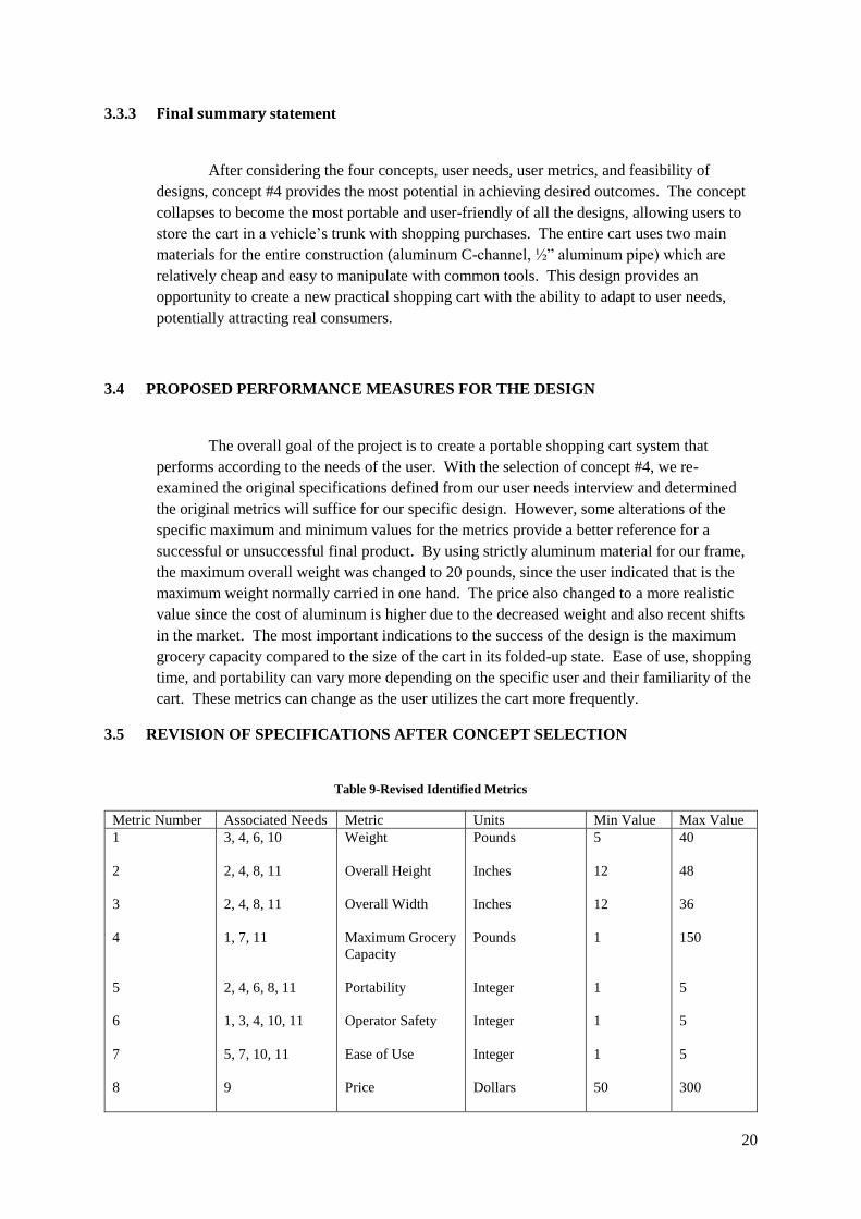
3.5 REVISION OF SPECIFICATIONS AFTER CONCEPT SELECTION
Table 9-Revised Identified Metrics
Metric Number Associated Needs Metric Units Min Value Max Value
1
2
3
4
5
6
7
8
3, 4, 6, 10
2, 4, 8, 11
2, 4, 8, 11
1, 7, 11
2, 4, 6, 8, 11
1, 3, 4, 10, 11
5, 7, 10, 11
9
Weight
Overall Height
Overall Width
Maximum Grocery
Capacity
Portability
Operator Safety
Ease of Use
Price
Pounds
Inches
Inches
Pounds
Integer
Integer
Integer
Dollars
5
12
12
1
1
1
1
50
40
48
36
150
5
5
5
300
21
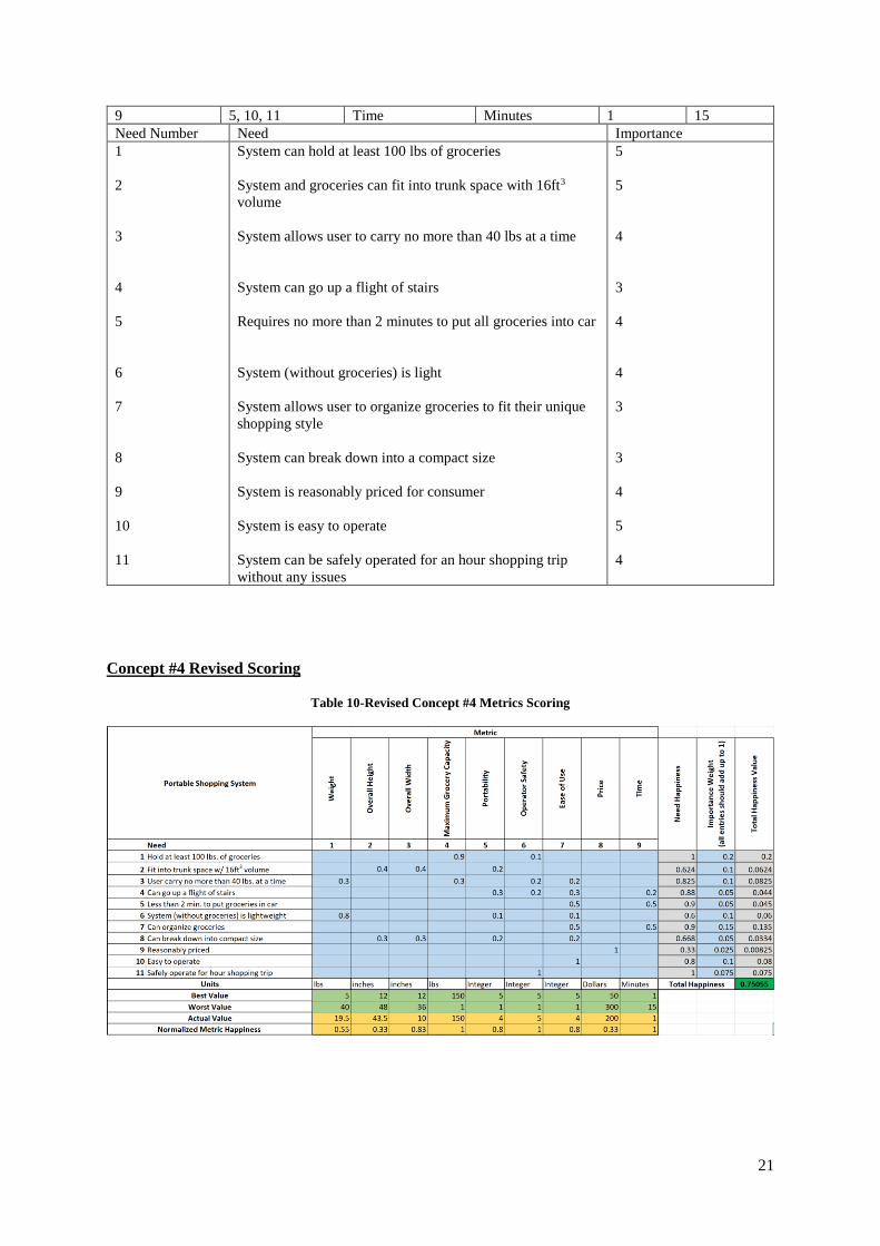
9 5, 10, 11 Time Minutes 1 15
Need Number Need Importance
1
2
3
4
5
6
7
8
9
10
11
System can hold at least 100 lbs of groceries
System and groceries can fit into trunk space with 16ft3
volume
System allows user to carry no more than 40 lbs at a time
System can go up a flight of stairs
Requires no more than 2 minutes to put all groceries into car
System (without groceries) is light
System allows user to organize groceries to fit their unique
shopping style
System can break down into a compact size
System is reasonably priced for consumer
System is easy to operate
System can be safely operated for an hour shopping trip
without any issues
5
5
4
3
4
4
3
3
4
5
4
Concept #4 Revised Scoring
Table 10-Revised Concept #4 Metrics Scoring
22
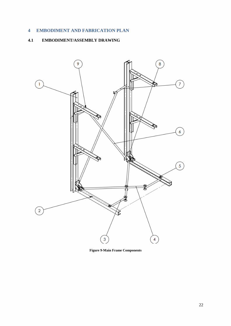
4 EMBODIMENT AND FABRICATION PLAN
4.1 EMBODIMENT/ASSEMBLY DRAWING
Figure 9-Main Frame Components
23
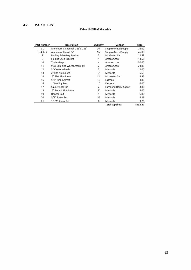
4.2 PARTS LIST
Table 11-Bill of Materials
24
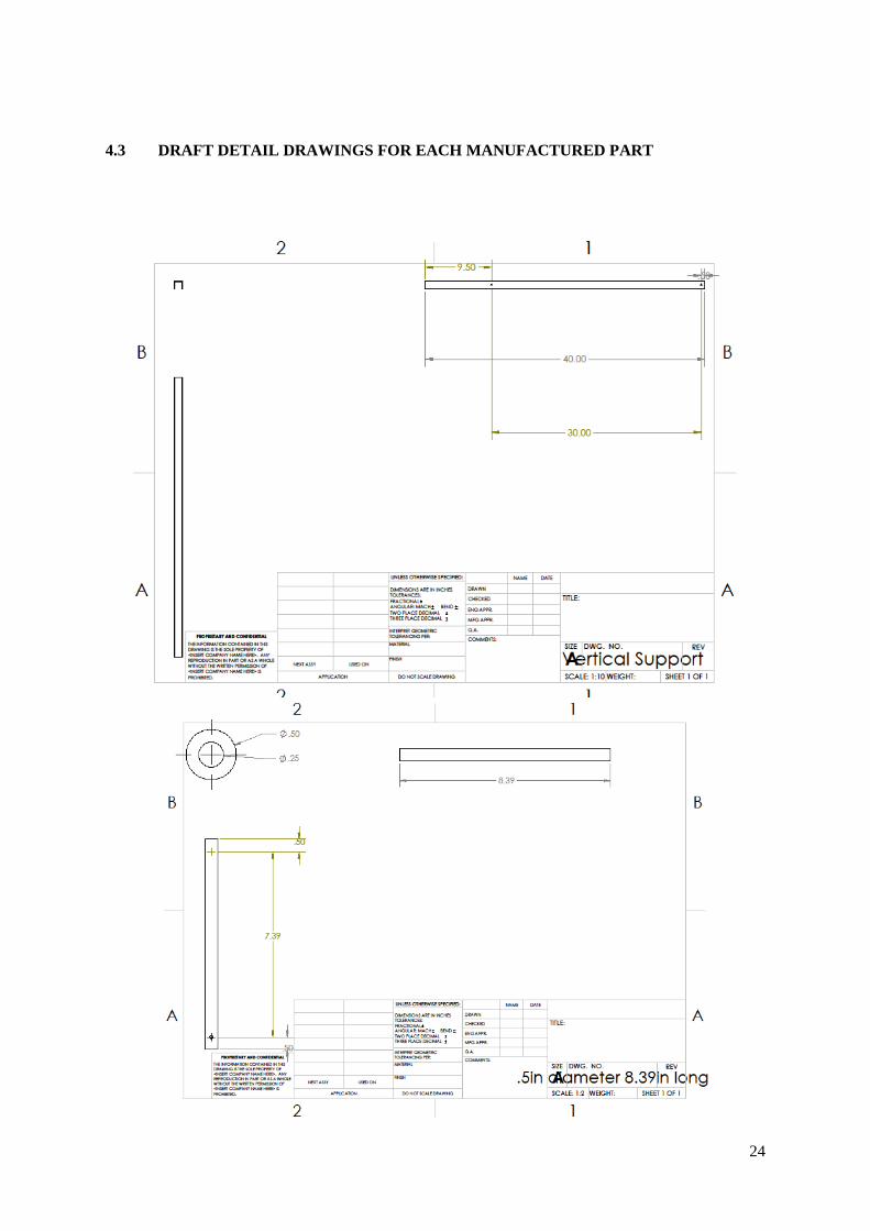
4.3 DRAFT DETAIL DRAWINGS FOR EACH MANUFACTURED PART
25
26
27
28
4.4 DESCRIPTION OF THE DESIGN RATIONALE
1. Vertical Aluminum C Channel: This component was selected for it’s ability to allow the
linkages to nestle inside of it when folded. For this reason, an inner diameter of one inch was
necessary. The beam was cut to 40” in length so as to closely mimic the height of traditional
carts. Aluminum was the choice material for all parts of the assembly, where applicable, to
minimize the weight of the entire cart.
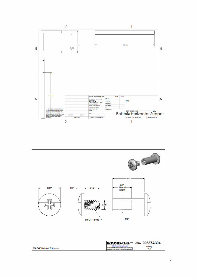
2. Horizontal Aluminum C Channel: As with the vertical framing, this component was selected
for it’s ability to fit the moving linkages. The length of this component was selected at 20” to
keep with the compatibility design. These outer framing parts were required to be 24” apart to
allow the Trolley Bags to fit properly on the assembled shelf arms.
3. 1/2” Aluminum Round Pipe: This component was selected so that it the two pinned pieces
together would snugly fit into the aluminum C channel when closed. This part was cut to 8.39
inches, with the 7/32” holes for the binding posts at ½” from the ends to meet the 7.39 inches
required for proper movement from the calculations. The end of this part attached to the C
channel was rounded off so movement was constrained at the flat end.
4. ½” Aluminum Round Pipe: This component was cut to 23.39 inches and connected part 3 to
adjacent horizontal C channel (part 3). The holes for binding posts were also cut at 7/32” ½”
from the ends of the ends.
5. Stainless Steel Binding Posts: Binding posts were the ideal fastener for this assembly to allow
the pinned pieces to smoothly articulate about each other. 5/8” length posts were used to
fasten the round piping to the C channel and 1” length posts were used to fasten the round
piping to another piece of round piping.
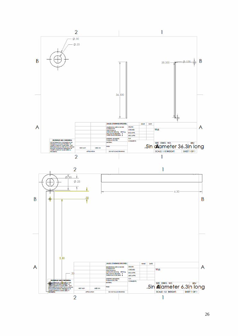
6. ½” Aluminum Round Piping: This component was selected for its lightweight materialistic
properties while also providing adequate support and length. It was cut to 36.3” long with
7/32” holes ½” from each end.
7. ½” Aluminum Round Piping: This component was used to secure the long vertical round
piping to the adjacent vertical C channel. It was cut to 6.3” to allow for proper kinematics so
as to not preclude the desired movements.
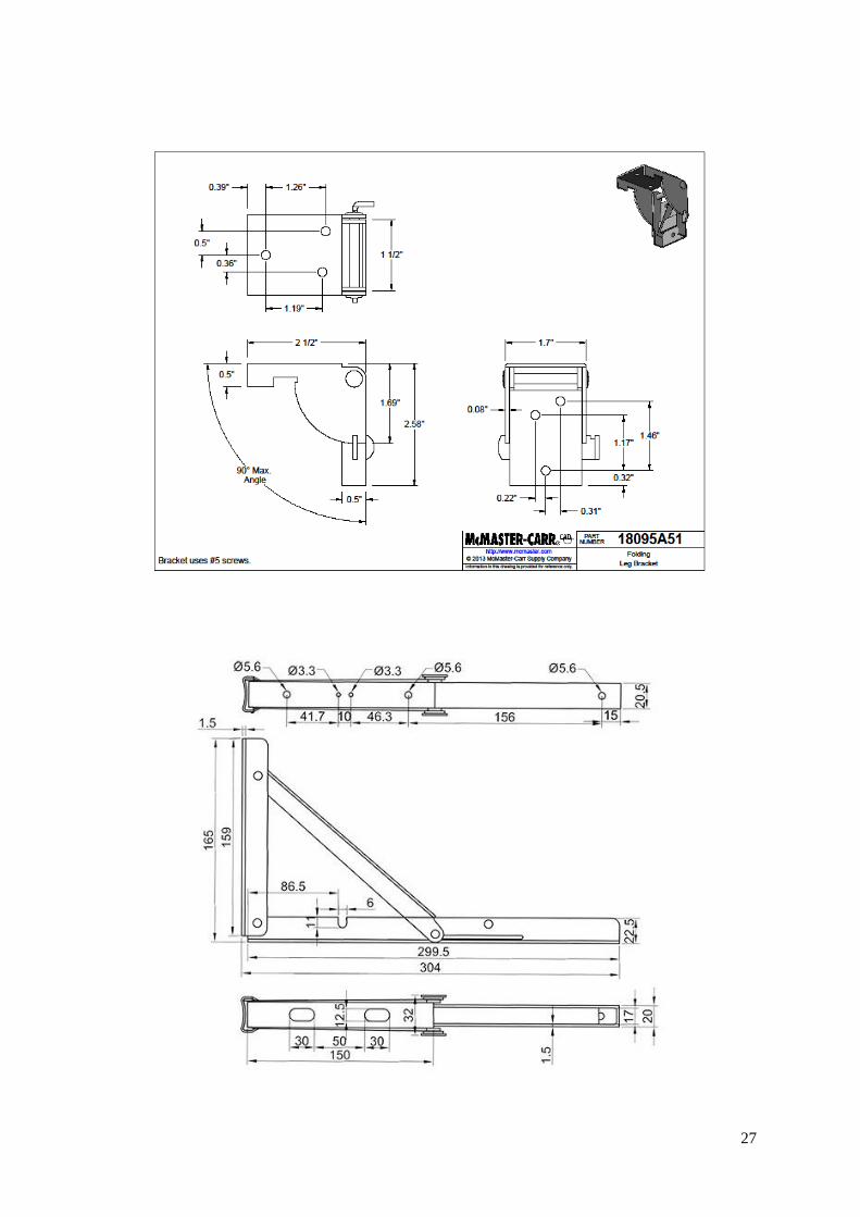
8. Folding Table Leg Bracket: This is a premanufactured part that was purchased from
McMaster Carr. It was chosen for it’s ease of hinge and ability to lock into position,
constraining the range of motion to only 0 or 90 degrees. This ensured that the cart would not
collapse during use or open when being transported.
9. Folding Shelf Bracket: This is another premanufactured part purchased from Amazon.com.
This part was chosen for its load rating of 600 pounds per pair of shelves, far exceeding the
design requirements. This shelf bracket also allowed for ease of locking the shelf arm into
place without having to add any other fabricated parts.
29
5 ENGINEERING ANALYSIS
5.1 ENGINEERING ANALYSIS PROPOSAL
5.1.1 Signed engineering analysis contract
30
5.2 ENGINEERING ANALYSIS RESULTS
5.2.1 Motivation
In order to ensure the shopping cart properly meets user needs, several analyses were
calculated prior to prototype embodiment. Before any fabrication of the cart began,
calculations were made to determine proper sizing, clearances, and capabilities of individual
parts and the assembly as a whole. This was imperative to be sure the cart could handle a full
load of groceries, assumed to be a maximum 100 pounds.
5.2.2 Summary statement of analysis done
Prior to physical embodiment, the shopping cart design was analyzed for proper fitment of
parts, including linkages, so as to not prohibit desired articulation. Analyses were also
required to utilize the most efficient materials for the overall design. Being that the portable
shopping cart’s purpose is to provide the user with a functional, lightweight, and durable
alternative to what is currently available, the cart was analyzed to adequately fit the user
needs while in both the open and compact positions.
5.2.3 Methodology
All analyses were calculated originally by hand then replicated and simulated in SolidWorks
in order to ensure producibility and accuracy. After fabrication of the prototype, the cart
underwent rigorous testing to verify results and capability.
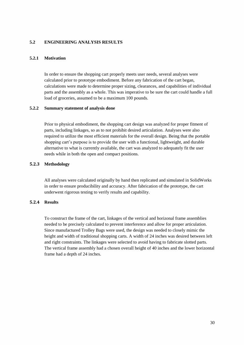
5.2.4 Results
To construct the frame of the cart, linkages of the vertical and horizonal frame assemblies
needed to be precisely calculated to prevent interference and allow for proper articulation.
Since manufactured Trolley Bags were used, the design was needed to closely mimic the
height and width of traditional shopping carts. A width of 24 inches was desired between left
and right constraints. The linkages were selected to avoid having to fabricate slotted parts.
The vertical frame assembly had a chosen overall height of 40 inches and the lower horizontal
frame had a depth of 24 inches.
31
Figure 10-Linkage Sizing Hand Calculations
32
After calculations were made for lengths of linkages, a degree of freedom analysis was
calculated to ensure the frame would articulate as required for our purposes. The top and
bottom frames were analyzed once, since they had the same linkages and mechanics. For this
analysis we used Gruebler’s Equation:
𝐷𝑂𝐹 = 3𝐿 − 2𝐽 − 3𝐺 (1)
Where DOF is degrees of freedom, L is number of linkages, J is number of joints, and G is
number of grounded links.
𝐷𝑂𝐹 = 3(6) − 2(7) − 3(0) (2)
Thus, resulting in four degrees of freedom, ensuring that after each link was pinned as
calculated, the desired movement would still be achievable.
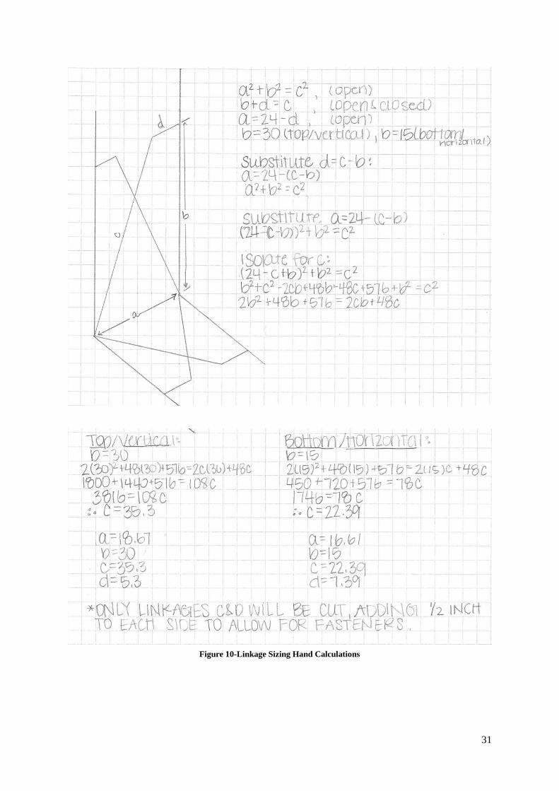
For the most vital purpose of the cart, to carry a heavy load of groceries, the manufactured
shelf brackets were rated for a 600 pound load per pair, far exceeding the design
requirements. The framing of the cart then was analyzed using SolidWorks Finite Element
Analysis to verify chosen materials and sizes would not fail under the given load.
Figure 11-Bottom Frame FEA
5.2.5 Significance
The calculation of all geometries for the linkages provided exact specifications for the sizing
of each part. Furthermore, the mathematical analysis of the each link proved the folding
ability of the frame to behave in the desired manner. The hardware securing each link was re-
examined after finding strict tolerances for the allowable articulation needed to operate
correctly without unwanted play in individual links. The overall analysis sustains the
kinematics potential of the design.
The Finite Element Analysis of the frame showed a potential issue of inward displacement of
the bottom horizontal C-channel pieces at the maximum proposed load. Additional
33
framework was proposed to reinforce the original design at these locations, even though our
FEA models did not indicate the design would catastrophically fail.
6 RISK ASSESSMENT
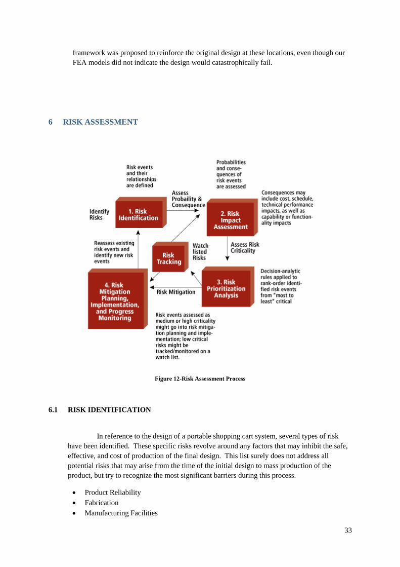
Figure 12-Risk Assessment Process
6.1 RISK IDENTIFICATION
In reference to the design of a portable shopping cart system, several types of risk
have been identified. These specific risks revolve around any factors that may inhibit the safe,
effective, and cost of production of the final design. This list surely does not address all
potential risks that may arise from the time of the initial design to mass production of the
product, but try to recognize the most significant barriers during this process.
• Product Reliability
• Fabrication
• Manufacturing Facilities
34
• User Preference
• Funding
• Liability
6.2 RISK ANALYSIS
6.2.1 Product Reliability
Risk associated with the continued use of the product over the course of time. Once
the product leaves a manufacturing facility, the time until service is required may
effect consumer perceptions.
Probability: High
Impact: High
6.2.2 Fabrication
Risk associated with issues in the ability to fabricate the design due to insufficient
materials, equipment, or knowledge.
Probability: Medium
Impact: Medium
6.2.3 Manufacturing Facilities
Risk associated with the inability to manufacture the product due to a lack of
manufacturing facilities being interested or capable of mass producing the design.
Probability: High
Impact: High
6.2.4 User Preference
Risk associated with potential users being comfortable with traditional designs and
refusal to change behaviors despite newer technology.
Probability: Medium
Impact: High
35
6.2.5 Funding
Risk associated with a lack of funding from investors or consumers.
Probability: Medium
Impact: High
6.2.6 Liability
Risk associated with potential injuries or accidents involving the product being used
by consumers.
Probability: Low
Impact: Medium
6.3 RISK MITIGATION
6.3.1 Product Reliability
The best way to address the reliability of the product over time is to conduct
extensive testing to determine the life cycle of the final end-product. Testing in many
different environments and circumstances attempts to mimic real world use of the
design. Also, expanding tests to involve situations outside normal operating
parameters may mitigate problems involved with the design being used in ways not
initially anticipated.
6.3.2 Fabrication
The potential to experience issues in the initial fabrication process can arise
due to a lack of required machinery/tools, unavailability of quality materials, or
simply a lack of properly trained and educated personnel. With the inability to use
WUSTL shop facilities, outside resources must be consulted to move the product
from paper to the end product. Even with proper resources, machine failures and
maintenance can impact timely fabrication of the design. The only way to mitigate
these risks is to have redundancy in available facilities and personnel.
36
6.3.3 Manufacturing Facilities
Existing manufacturing facilities usually have an existing workload that keeps
the workforce and resources unavailable to accept more work. Finding a facility
willing to commit to providing all necessary manufacturing of a product involves
persistent venturing and communication with a multitude of possibilities. To really
mass produce the design, the construction of new manufacturing facilities is the only
real way to ensure that quality production is the top priority. Redundancy in available
facilities alleviates potential delays if a single site is compromised for any reason.
6.3.4 User Preference
Since the traditional shopping cart has remained unchanged for decades,
introducing an entirely new design may not generate excitement in potential users
immediately. Marketing campaigns can be developed to understand and possibly
alter consumer perceptions once the product is available. Educating the masses on
the improvements of the new design over the traditional design may sway some
individuals to utilizing the new product, but others will always be reluctant to change.
Consumer attitudes may shift over time with proven use of the new portable shopping
system, but multiple marketing efforts will be required to boost potential sales and
profits.
6.3.5 Funding
Securing unlimited funding for the development of a product is impossible.
Efforts to attract investors is the only way to sustain adequate funding throughout the
entire design to production process. Obtaining a line of credit can help in short-term
gaps of funding, but relying solely on credit without available capital surely will not
lead to profits. The responsibility of attracting new sources of funding falls on every
individual involved in the development of a new product.
6.3.6 Liability
Eliminating potential risk of injury or property damage caused by the designed
product is vital. Constant assessments regarding the safety of the product can help
solve potential problems and prevent loss of funds in the form of lawsuits. Creating
proper labeling and instructional material will educate the consumer regarding the
product and its safe usage. To protect designers or the parent company, liability
insurance should be kept current. Legal teams need to be consulted as well to review
potential risks before making the product available to the public. After a product hits
37
the market, records need to be kept on any reported safety issues or incidents to
identify areas of the design that require alteration.
7 CODES AND STANDARDS
7.1 IDENTIFICATION
ASTM F2372 – 15: Standard Consumer Safety Performance Specification for Shopping Carts
Purpose and scope
1.1 This consumer safety performance specification covers performance requirements, test
methods, and labeling requirements for shopping carts and restraint systems.
1.2 This specification is intended to cover children who are at least six months of age and at
least 15 lb (7 kg) up to children who are not more than four years of age and who weigh no
more than 35 lb (16 kg).
1.3 This specification does not include any provisions nor is intended for use of infant carriers.
1.4 No shopping cart or restraint system produced after the approval date of this consumer
safety performance specification shall, either by label or other means, indicate compliance with
this specification unless it conforms to all requirements herein.
1.5 The values stated in inch-pound units are to be regarded as standard. The values given in
parentheses are mathematical conversions to SI units that are provided for information only and
are not considered standard.
1.6 The following precautionary caveat pertains only to the test method portion, Section 7, of
this specification. This standard does not purport to address all of the safety concerns, if any,
associated with its use. It is the responsibility of the user of this standard to establish
appropriate safety and health practices and determine the applicability of regulatory
limitations prior to use.
[ASTM F2372-15, Standard Consumer Safety Performance Specification for Shopping Carts,
ASTM International, West Conshohocken, PA, 2015, www.astm.org]
7.2 JUSTIFICATION
38
Justification for ASTM F2372-15
This standard was created to regulate the safety of shopping carts, specifically pertaining to the
child restraints and seats. The document insists upon specific means of testing, labeling, and
performance of the design. If the shopping cart is intended to provide children with a seat, then
it must also be equipped with a functional restraint system that can adjust depending on the
child’s age and size. This standard covers children from 6 months of age and at least 15
pounds up to children weighing 35 pounds.
7.3 DESIGN CONSTRAINTS
7.3.1 Safety
The standard above place constraints on the required safety equipment needed in our design if
it is intended for children to be placed in the cart. Functional and adjustable restraints must
be present if any type of seat is available. Testing of required restraints is also mandated by
specific modes of testing and will add time and cost the overall project. Our design will not
include a child seat to mitigate the excessive constraints outlined by this standard.
7.3.2 Legal
The standard above places a constraint on the type of labeling that may be legally place on the
product. Without compliance with all the standards outline, the cart must visibly show
signage that indicates the device should not be used to transport children in any manner. By
stating this clearly and in multiple locations, legal ramifications should be minimized for any
improper use of the shopping cart.
7.4 SIGNIFICANCE
The ASTM standard presented enough constraints on the design that the choice was made to
not include a child seat into our final product. Without the ability to test our product in the
proscribed manner, excessive time and resources must be spent to fulfill all the obligations
outlined in the standard. The threat of legal liability increases the risks significantly enough
to deter including anything that falls within the scope of the standard to be involved. The
final product will abide by the standard since it will be branded and marketed to be used
without children.
39
8 WORKING PROTOTYPE
8.1 PROTOTYPE PHOTOS
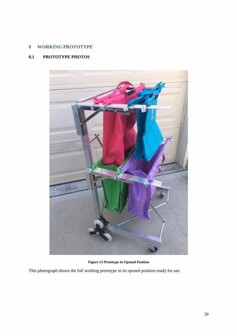
Figure 13-Prototype in Opened Position
This photograph shows the full working prototype in its opened position ready for use.
40
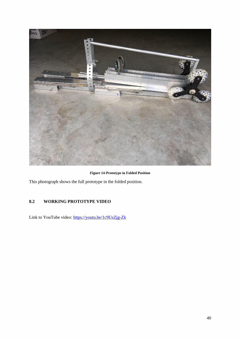
Figure 14-Prototype in Folded Position
This photograph shows the full prototype in the folded position.
8.2 WORKING PROTOTYPE VIDEO
Link to YouTube video: https://youtu.be/1c9UsZjg-Zk
41
8.3 PROTOTYPE COMPONENTS
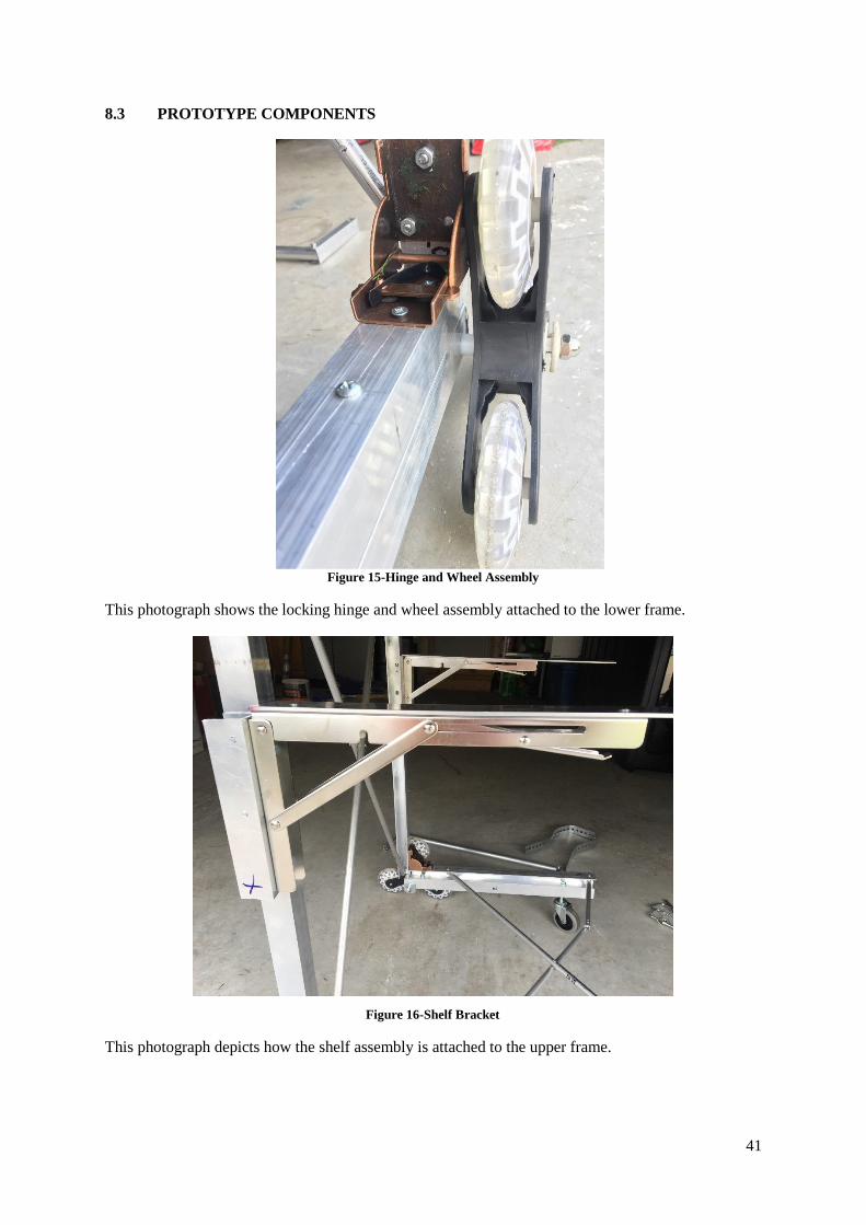
This photograph shows the locking hinge and wheel assembly attached to the lower frame.
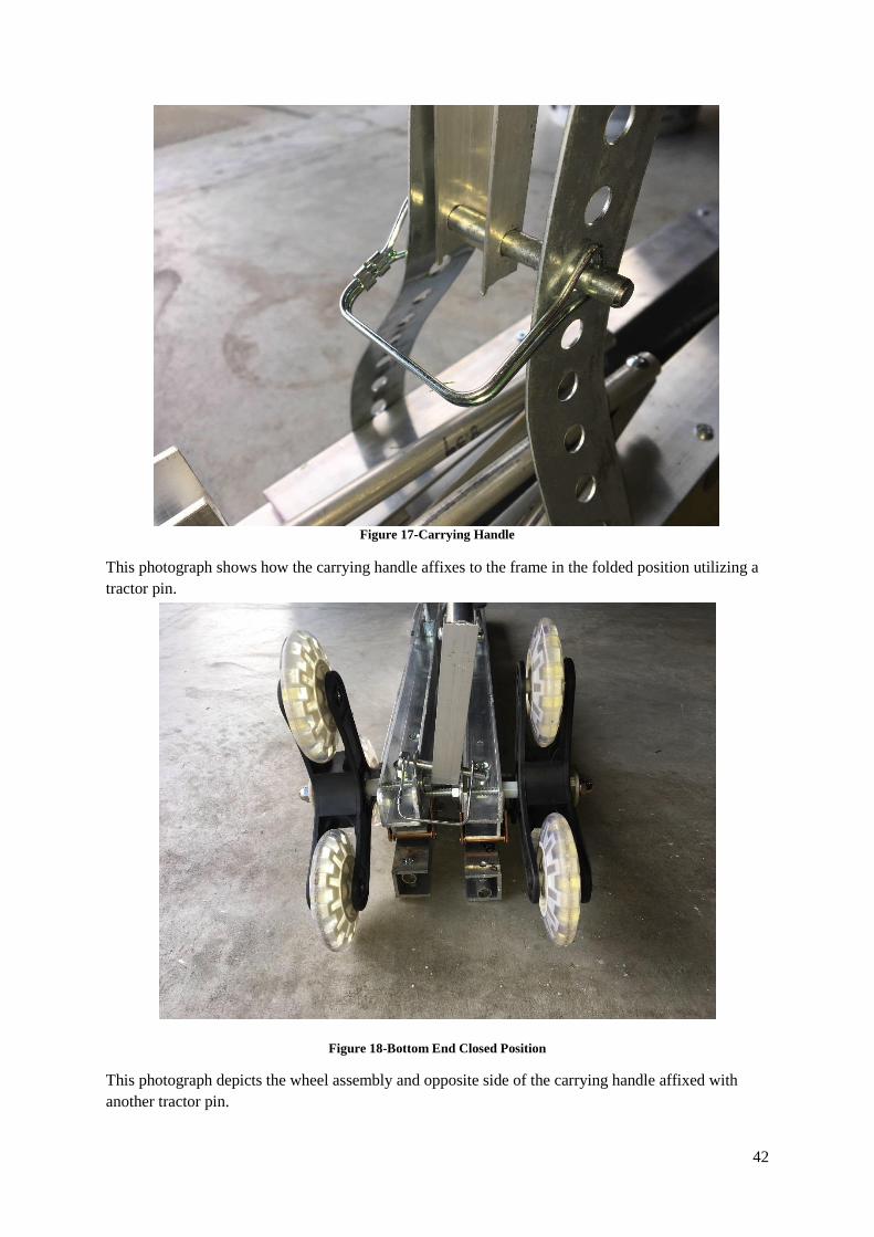
This photograph depicts how the shelf assembly is attached to the upper frame.
Figure 15-Hinge and Wheel Assembly
Figure 16-Shelf Bracket
42
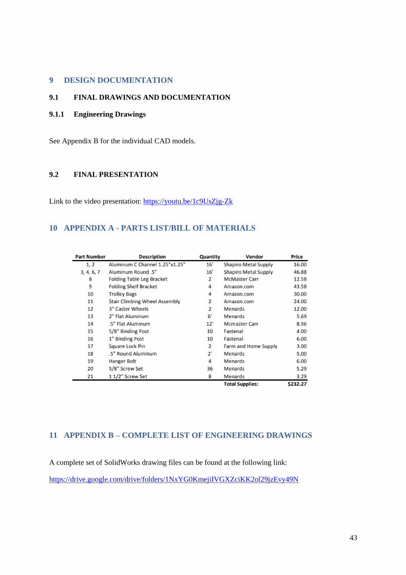
This photograph shows how the carrying handle affixes to the frame in the folded position utilizing a
tractor pin.
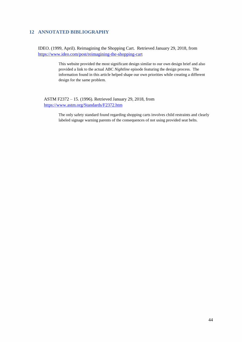
This photograph depicts the wheel assembly and opposite side of the carrying handle affixed with
another tractor pin.
Figure 17-Carrying Handle
Figure 18-Bottom End Closed Position
43
9 DESIGN DOCUMENTATION
9.1 FINAL DRAWINGS AND DOCUMENTATION
9.1.1 Engineering Drawings
See Appendix B for the individual CAD models.
9.2 FINAL PRESENTATION
Link to the video presentation: https://youtu.be/1c9UsZjg-Zk
10 APPENDIX A - PARTS LIST/BILL OF MATERIALS
11 APPENDIX B – COMPLETE LIST OF ENGINEERING DRAWINGS
A complete set of SolidWorks drawing files can be found at the following link:
https://drive.google.com/drive/folders/1NxYG0KmejiIVGXZciKK2ol29jzEvy49N
44
12 ANNOTATED BIBLIOGRAPHY
IDEO. (1999, April). Reimagining the Shopping Cart. Retrieved January 29, 2018, from
https://www.ideo.com/post/reimagining-the-shopping-cart
This website provided the most significant design similar to our own design brief and also
provided a link to the actual ABC Nightline episode featuring the design process. The
information found in this article helped shape our own priorities while creating a different
design for the same problem.
ASTM F2372 – 15. (1996). Retrieved January 29, 2018, from
https://www.astm.org/Standards/F2372.htm
The only safety standard found regarding shopping carts involves child restraints and clearly
labeled signage warning parents of the consequences of not using provided seat belts.