Embed Size (px)
Citation preview
U.S. Department of Justice Office of Justice Programs National Institute of Justice
Law Enforcement and Corrections Standards and Testing Program
DE
C. 0
7
NIJ Standard– 0603.01
Portable X-Ray Systems for Use in Bomb Identification
www.ojp.usdoj.gov/nij
Office of Justice Programs Innovation • Partnerships • Safer Neighborhoods
www.ojp.usdoj.gov

U.S. Department of Justice
Office of Justice Programs
810 Seventh Street N.W.
Washington, DC 20531
Michael B. Mukasey
Attorney General
Cybele K. Daley
Acting Assistant Attorney General
David W. Hagy
Acting Principal Deputy Director, National Institute of Justice
This and other publications and products of the National Institute
of Justice can be found at:
National Institute of Justice
www.ojp.usdoj.gov/nij
Office of Justice Programs
Innovation • Partnerships • Safer Neighborhoods
www.ojp.usdoj.gov
U.S. Department of Justice Office of Justice Programs National Institute of Justice
Portable X-Ray Systems for Use in Bomb Identification
NIJ Standard–0603.01 Supersedes NILECJ–STD–0603.00, X-Ray Systems for Bomb Disarmament, dated June 1975
Coordination by: Office of Law Enforcement Standards National Institute of Standards and Technology Gaithersburg, MD 20899–8102
Prepared for: National Institute of Justice Office of Science and Technology Washington, DC 20531
December 2007
NCJ 218586

National Institute of Justice
David W. Hagy Acting Principal Deputy Director
This standard was prepared for the National Institute of Justice, U.S. Department of Justice, by the Office of Law Enforcement Standards (OLES) of the National Institute of Standards and Technology (NIST) under Interagency Agreement Number IA2003–IJ–R–029, Project No. 06–001.
This standard was developed under the direction of Nicholas Paulter, Program Manager for Detection, Inspection, and Enforcement Technologies, and Kathleen M. Higgins, Director of OLES.

FOREWORD
The Office of Law Enforcement Standards (OLES) of the National Institute of Standards and Technology (NIST) furnishes technical support to the National Institute of Justice (NIJ) program to support law enforcement and criminal justice in the United States. OLES’s function is to develop standards and conduct research that will assist law enforcement and criminal justice agencies.
OLES is: (1) subjecting existing equipment to laboratory testing and evaluation, and (2) conducting research leading to the development of several series of documents, including national standards, user guides, and technical reports.
This document covers research conducted by OLES in collaboration with the Police Scientific Development Branch in the United Kingdom under the sponsorship of NIJ. Additional reports as well as other documents are being issued under the OLES program in the areas of protective clothing and equipment, communications systems, emergency equipment, investigative aids, security systems, vehicles, weapons, and analytical techniques and standard reference materials used by the forensic community.
Technical comments and suggestions concerning this guide are invited from all interested parties. They may be addressed to the Office of Law Enforcement Standards, National Institute of Standards and Technology, 100 Bureau Drive, Stop 8102, Gaithersburg, MD 20899−8102.
David W. Hagy Acting Principal Deputy Director, National Institute of Justice
iii
CONTENTS
Page FOREWORD ................................................................................................................................. iii COMMONLY USED SYMBOLS AND ABBREVIATIONS........................................................v I. INTRODUCTION ..................................................................................................................1
1.1 Purpose and Scope .........................................................................................................1 1.2 Classification .................................................................................................................1 1.3 Definitions .....................................................................................................................1
2. REQUIREMENTS..................................................................................................................3 2.1 Minimum Performance Specifications ..........................................................................3 2.2 System Requirements.....................................................................................................4 2.3 Operating Requirements ................................................................................................7 2.4 Support Requirements....................................................................................................8
3. TEST METHODS.................................................................................................................10 3.1 Minimum Performance Specifications ........................................................................10 3.2 System Requirements...................................................................................................12 3.3 Operating Requirements ..............................................................................................14 3.4 Support Requirements..................................................................................................15 3.5 Standard Test Conditions.............................................................................................16 3.6 Test Equipment ............................................................................................................16 3.7 Test Patterns.................................................................................................................17
4. REFERENCES .....................................................................................................................19
FIGURES
Figure 1. Setup for Image Quality Test ........................................................................................11 Figure 2. Positioning of Radiation Monitor for Leakage Radiation Test .....................................13 Figure 3. Plan View of the Portable X-Ray Test Pattern..............................................................17 Figure 4. The Components of the Portable X-Ray Test Pattern ...................................................18
iv

COMMONLY USED SYMBOLS AND ABBREVIATIONS A ampere H henry nm nanometer ac alternating current h hour No. number AM amplitude modulation hf high frequency o.d. outside diameter cd candela Hz hertz Ω ohm cm centimeter i.d. inside diameter p. page CP chemically pure in inch Pa pascal c/s cycle per second IR infrared pe probable error D day J joule pp. pages dB decibel L lambert ppm parts per million dc direct current L liter qt quart °C degree Celsius lb pound rad radian °F degree Fahrenheit lbf pound-force rf radio frequency dia diameter lbf�in pound-force inch rh relative humidity emf electromotive force lm lumen s second eq equation ln logarithm (base e) SD standard deviation F farad log logarithm (base 10) sec. section fc footcandle M molar Sv sievert fig. figure m meter SWR standing wave ratio FM frequency modulation min minute uhf ultrahigh frequency ft foot mm millimeter UV ultraviolet ft/s foot per second mph mile per hour V volt g acceleration m/s meter per second vhf very high frequency g gram mSv millisievert W watt gr grain N newton λ wavelength
N�m newton meter wt weight
area=unit2 (e.g., ft2, in2, etc.); volume=unit3 (e.g., ft3, m3, etc.)
PREFIXES COMMON CONVERSIONS (See ASTM E380)
d deci (10-1) da deka (10) 0.30480 m =1 ft 4.448222 N = 1 lbf c centi (10-2) h hecto (102) 25.4 mm = 1 in 1.355818 J = 1 ft�lbf m milli (10-3) k kilo (103) 0.4535924 kg = 1 lb 0.1129848 N�m = 1 lbf�in µ micro (10-6) M mega (106) 0.06479891 g = 1 gr 14.59390 N/m = 1 lbf/ft n nano (10-9) G giga (109) 0.9463529 L = 1 qt 6894.757 Pa = 1 lbf/in2
p pico (10-12) T tera (1012) 3600000 J = 1 kW�hr 1.609344 km/h = 1 mph
Temperature: T°C = (T°F-32)×5/9 Temperature: T°F = (T°C×9/5)+32
v


NIJ Standard–0603.01
NIJ STANDARD FOR PORTABLE X-RAY SYSTEMS FOR USE IN BOMB IDENTIFICATION
1. INTRODUCTION
1.1 Purpose and Scope
The purpose of this standard is to establish performance requirements and testing methods for portable x-ray systems for use in bomb disarming operations. This standard does not apply to cabinet x-ray systems, such as those used for security screening.
1.2 Classification
1.2.1 Type I. Battery Powered Portable X-Ray Systems
A portable x-ray system entirely powered by low-voltage batteries.
1.2.2 Type II. Optional Powered Portable X-Ray Systems
Portable x-ray systems for which the operator can select either low-voltage battery or AC-mains powered operation.
1.3 Definitions
Comprises all the component units used in the production, capture, display, and storage of an x-ray image. All defined terms are presented in italics within this document.
1.3.1 Anode
The positive electrode/terminal of an electrical device. In x-ray tubes, the anode is typically made of tungsten and produces x-rays when bombarded by high energy electrons.
1.3.2 Aperture
The surface on the x-ray generator module from which the useful x-ray beam exits and which is in a plane normal to the beam direction.
1.3.3 Control and Display Unit
The component of the portable x-ray system that enables the operator to activate and control x-ray generation and display the images obtained with the image capture unit. Typical methods currently used for image display include instant-print film, cathode-ray tubes, and flat panel displays.
1

1.3.4 Exposure
For radiation protection purposes, exposure to ionizing radiation is measured as dose equivalent. This is defined as the amount of any type of radiation that, when absorbed in a biological system, results in the same biological effect as one unit of absorbed dose delivered in the form of low-linear-energy transfer radiation. The unit of dose equivalent is the sievert (Sv).
1.3.5 Field of View
The horizontal and vertical extent of the target plane that is to be imaged.
1.3.6 Image Acquisition Period
The interval required to capture (or expose) the image and then to display (or process) the image. The image acquisition period does not include the time required to retrieve the film from the image capture unit and then convey the film to the control and display unit.
1.3.7 Image Capture Unit
The component of the portable x-ray system that is used to acquire the x-ray image. Typical methods currently used include film and solid-state digital imaging arrays.
1.3.8 Portable X-Ray System
A man-portable self-contained x-ray system used to acquire images for bomb diagnostics and render safe procedures. The portable x-ray system comprises the x-ray generator module, the image capture unit, and the control and display unit.
1.3.9 Radiation, Ionizing
Any electromagnetic or particulate radiation capable of producing ions, directly or indirectly, by interaction with matter.
1.3.10 Radiation, Leakage
All ionizing radiation, except the useful beam, coming from an x-ray generator module.
1.3.11 Radiation, Primary
Ionizing radiation coming directly from an x-ray tube anode and passing through the aperture.
1.3.12 Radiation, Scattered
Ionizing radiation that, during passage through matter, has been deviated in direction and usually has had its energy diminished.
1.3.13 Target
An object that is imaged by the portable x-ray system. The target can also be a test pattern.
2

1.3.14 Target Plane
The plane (imaginary flat surface) extending vertically and horizontally from the center of the target. The target plane is perpendicular to the direction of the x-ray beam.
1.3.15 Useful X-Ray Beam
That part of the primary and scattered radiation, which passes through an aperture, cone, or other collimating device.
1.3.16 X-Ray Generator Module
That part of a portable x-ray system comprising the x-ray tube, shielding material, any permanently attached devices (collimators) used to restrict the field of the useful x-ray beam, and the high-voltage power supply. The x-ray tube is often a field-replaceable component.
1.3.17 X-Ray Output Power
The power output of the x-ray generator module, expressed as either the number of pulses for a pulsed x-ray generator or the combined values of kV and mA for a continuous-wave x-ray generator.
2. REQUIREMENTS
2.1 Minimum Performance Specifications
The specifications listed in this section are those directly relating to the function of the portable x-ray system, which is to provide x-ray images.
2.1.1 Image Quality
The portable x-ray system shall be able to fully resolve the copper resolution grids (see figure 3, lower left corner and upper right corner, pattern containing copper wires) and be capable of permitting all of the 33 AWG tungsten wires of the test pattern behind 10 mm (0.4 in) of steel to be seen. The lead corner pieces of the test pattern shall also be clearly visible when tested in accordance with the image quality test of section 3.1.1.
2.1.2 Field of View
The x-ray generator module of the portable x-ray system shall be capable of providing an exposure area of at least 39.1 cm vertical by 39.1 cm horizontal (15.4 in vertical x 15.4 in horizontal) at a source-to-target distance of 59 cm ± 5 cm (24 in ± 2 in), and the exposure area shall meet the requirements of section 2.1.1 as tested per section 3.1.1.
2.1.3 Image Acquisition Period
The image acquisition period shall not exceed 240 s.
3
2.1.4 Image Extent
The image capture unit shall be capable of providing image information to within 12 mm or less of the surface on which it is placed with no degradation of image quality, as defined in section 2.1.1, over the entire surface of the image.
2.2 System Requirements
The requirements listed in this section affect the functional performance or use of the instrument.
2.2.1 Safety
2.2.1.1 Leakage Radiation
The average exposure of leakage radiation from the x-ray generator shall not exceed 1 mSv in any 1 h period of operation, when measured in accordance with the leakage radiation test of section 3.2.1.1.
2.2.1.2 Electrical Safety
The portable x-ray system shall meet the applicable requirements of UL 61010A–1, as amended; and/or IEC 61010–1, as amended, IEC 60601–2–7, as amended, and IEC 60601–2–28, as amended.
2.2.2 Electromagnetic Compatibility
The equipment shall meet the applicable requirements for susceptibility to interference from electromagnetic radiation and for emission of electromagnetic interference.
2.2.2.1 Emissions
2.2.2.1.1 Radiated Emission
The portable x-ray system, when adjusted to meet the requirements of section 2.1, shall meet the requirements of 47 CFR Part 18, as amended, and/or CISPR 11, as amended.
2.2.2.2 Susceptibility
The x-ray generator module is not subject to the requirements of susceptibility.
2.2.2.2.1 Radiated Susceptibility, Electrostatic Discharge
The portable x-ray system, when adjusted to meet the requirements of section 2.1, shall not malfunction when tested in accordance with IEC 61000–4–2, as amended, and using the test specifications given in IEC 61000–6–1, as amended, for contact discharge.
4
2.2.2.2.2 Radiated Susceptibility, RF Emissions
The portable x-ray system, when adjusted to meet the requirements of section 2.1, shall not malfunction when tested in accordance with IEC 61000–4–3, as amended, and using the test specifications given in IEC 61000–6–1, as amended.
2.2.2.2.3 Radiated Susceptibility, Electrical Fast Transient/Burst
The portable x-ray system, when adjusted to meet the requirements of section 2.1, shall not malfunction when tested in accordance with IEC 61000–4–4, as amended, and using the test specifications given in IEC 61000–6–1, as amended
2.2.2.2.4 Conducted Susceptibility, Radio Frequency Common Mode
If applicable, the portable x-ray system, when adjusted to meet the requirements of section 2.1, shall not malfunction when tested in accordance with IEC 61000–4–6, as amended, and using the test specifications given in IEC 61000–6–1, as amended.
2.2.2.2.5 Conducted Susceptibility, Surges
If applicable, the portable x-ray system, when adjusted to meet the requirements of section 2.1, shall not malfunction when tested in accordance with IEC 61000–4–5, as amended, and using the test specifications given in IEC 61000–6–1, as amended.
2.2.2.2.6 Conducted Susceptibility, Power Frequency Common Mode
If applicable, the portable x-ray system, when adjusted to meet the requirements of section 2.1, shall not malfunction when tested in accordance with IEC 61000–4–8, as amended, and using the test specifications given in IEC 61000–6–1, as amended.
2.2.2.2.7 Conducted Susceptibility, Voltage Dips and Interruptions
If applicable, the portable x-ray system, when adjusted to meet the requirements of section 2.1, shall not malfunction when tested in accordance with IEC 61000–4–11, as amended, and using the test specifications given in IEC 61000–6–1, as amended.
2.2.3 Power
Battery-powered portable x-ray systems shall meet the image quality requirement of section 2.1.1 when tested in accordance with the image quality test of section 3.1.1.
All batteries used in the portable x-ray system shall be of a type that are easily replaced or recharged.
5
2.2.4 Ruggedness
2.2.4.1 Bump
The portable x-ray system shall meet the leakage radiation requirement of section 2.2.1.1 and the image quality requirements of section 2.1.1 after being tested in accordance with the requirements of IEC 60068–2–29, 1987, as amended, using 100 bumps applied to each of the six sides (top, bottom, left, right, front, and back) of each component of the portable x-ray system with each bump having a nominal peak acceleration of 15 g (150 m/s2) and a nominal pulse duration of 6 ms.
2.2.4.2 Drop
The portable x-ray system shall meet the leakage radiation requirement of section 2.2.1.1 and the image quality requirements of section 2.1.1 after each component (x-ray generator module, image capture unit, and control and display unit), properly contained within its transport case, has been tested in accordance with the requirements of IEC 68–2–32 Procedure 1, 1975, for each face and corner of the component when contained within its transport case and a fall height of 0.3 m ± 0.03 m.
2.2.5 Environmental Requirements
2.2.5.1 Temperature Stability and Range
The portable x-ray system shall operate over the ambient temperature range of at least -18 °C to 43.5 °C (0 °F to 110 °F). The portable x-ray system shall be tested in accordance with MIL– STD–810F Method 501.4, as amended, Procedure II, at 43.5 °C ± 3 °C (110 °F ± 5.4 °F) after being exposed to that temperature continuously for 24 h ± 1 h. The portable x-ray system then shall be cooled to -18 °C ± 3 °C (0 °F ± 5.4 °F) within 4 h ± 0.5 h and tested in accordance with MIL–STD–810F Method 502.4, as amended, Procedure II, at -18 °C ± 3 °C (0 °F ± 5.4 °F) after being exposed to that temperature continuously for 24 h ± 1 h.
2.2.5.2 Relative Humidity Stability and Range
The detector shall be tested in accordance with the requirements of MIL–STD–810F Method 507.4, Procedure III, 10 cycles, as amended.
2.2.5.3 Environmental Protection
The portable x-ray system shall meet or exceed the requirements for compliance with IEC 60529, as amended, classification IP54.
The portable x-ray system shall meet the leakage radiation requirement of section 2.2.1.1 and the image quality requirements of section 2.1.1 after being subjected to temperature and relative humidity in accordance with the environmental tests of section 3.2.5.
6
2.2.6 Tripod Support
The x-ray generator module shall be capable of being affixed to a photographer’s tripod having a ¼-20 UNC (¼ in BSW) thread mount.
2.3 Operating Requirements
The requirements listed in this section affect how the portable x-ray system is operated and do not affect its functional performance.
2.3.1 Remote Control and Viewing
The portable x-ray system shall have an activation device that permits the generation of x-rays only when actuated by the operator. The activation device and any image-viewing screen shall both be remotely operable at a location that is greater than 6 m (20 ft) from the generator.
2.3.2 Exposure Control
Portable x-ray systems that utilize sensitized media to record images shall be key activated to prevent unintended or accidental exposure of the media. The portable x-ray system shall be designed so that it cannot operate without the interlocking key and so that the interlocking key cannot be removed while the portable x-ray system is operating.
2.3.2.1 Exposure Delay
The portable x-ray system shall have a means by which the operator can delay the exposure by at least 1 min from the instant of activation.
2.3.3 Indicators
2.3.3.1 X-Ray Emission Warning Alarm
2.3.3.1.1 Audible Alarm
The x-ray generator module shall have an audible warning device that indicates when it is powered and in a state of readiness to emit radiation, when and if the timer of the exposure delay (see sec. 2.3.2.1) has been activated and is in a state of counting down to emission, and when it is emitting radiation. The audible alarm for these three states shall be distinguishable. The audible indicator shall produce an alarm-state sound pressure level (SPL) of 85 dBSPL ± 5 dBSPL at a distance of 80 cm (31 in) from the detector as measured in accordance with the audible alarm test of section 3.3.3.1.1.
2.3.3.1.2 Visual Alarm
The x-ray generator module shall have a visual warning device that indicates when it is powered and in a state of readiness to emit radiation, when and if the timer of the exposure delay (see sec. 2.3.2.1) has been activated and is in a state of counting down to emission, and when it is emitting radiation. The visual alarm for these three states shall be distinguishable. The visual indicator
7
shall be readily observable when tested in accordance with the visual alarm test of section 3.3.3.1.2. The visual indication on the x-ray generator module shall be the same as when operated remotely via computer control.
2.3.3.2 Control Software
2.3.3.2.1 Exposure Control
The control software shall not allow the operator to adjust the x-ray output power to a value less than the minimum operational requirement for a given pairing of x-ray generator module and image capture unit.
2.3.3.2.2 Countdown Alarm
The control and display unit either shall provide a countdown alarm that emulates that provided by the x-ray generator module when it is operated in manual mode or shall not affect the alarm indications on the x-ray generator module when operated remotely via the control and display unit.
2.3.4 Portability
The entire portable x-ray system, including carrying cases and any required battery charger shall have a total weight less than 50 kg (110 lb). The maximum weight of any one component of the portable x-ray system shall be less than 16 kg (35 lb).
2.3.5 Switch Size
Any switch or push button on the x-ray generator module shall have a contact area of at least 5 mm by 5 mm or a diameter of at least 5 mm.
2.3.6 Power-On Delay
The x-ray generator module, when controlled remotely via the control and display unit, shall have a minimum delay of 60 s between the time the power switch on the x-ray generator module is toggled to the on position and the time the x-ray generator module becomes powered.
2.4 Support Requirements
The requirements listed in this section ensure that support of the portable x-ray system is provided by the manufacturer.
2.4.1 Manufacturer-Provided Equipment
The manufacturer shall supply any adapters or unique test equipment required to test the portable x-ray system. Such equipment shall remain the property of the supplier and be returned upon completion of testing unless other agreements are made.
8

2.4.1.1 Battery Tester
The manufacturer shall provide an instrument for testing the status of the batteries used in the portable x-ray system.
2.4.2 Manufacturer-Provided Information
A printed operators’ manual shall be provided by the manufacturer or distributor with each portable x-ray system. This manual shall clearly state, in English, the instructions for the interconnection, checkout, operation, and maintenance of the complete portable x-ray system and shall:
• Inform the user concerning government regulations and industry standards applicable to the operation of portable x-ray systems in the country where the system is to be sold.
• Inform the user of the need for proper training and supervision in the use of portable x-ray systems and discuss the hazards involved in improper use.
• Describe the appropriate personnel radiation monitoring devices for use with the portable x-ray system. Such instructions may include references to specific commercially available monitoring devices, and shall include a description of the radiation encountered and how the radiation should be measured.
• Provide information relative to optimizing the imaging of objects, such as collimator, settings, and use of grids.
• List recommended aperture-to-object distances for various object sizes.
• List recommended exposure settings for these recommended distances and various types of objects (such as pipe bombs, shoebox bombs, etc.).
• Provide recommended distances between the aperture and the image capture unit to ensure full exposure of the active area of the image capture unit.
• Provide typically safe distances from and in front of the aperture in open-air conditions.
• State the approximate operational time before battery replacement or recharging is necessary for the x-ray generator module when the maximum x-ray output power is selected and for the digital image capture unit, if used.
• If the x-ray tube is capable of being changed in the field, state the tools necessary to enable this.
• Provide an indication of the recommended extremes of operating and storage temperatures.
9
• If the portable x-ray system has the ability to use a wireless link for control purposes, it shall be stated that the rf wireless system may be subject to electromagnetic interference, which may cause the x-ray source to emit accidentally.
• The manufacturer shall provide information indicating the allowed pairings of x-ray generator module and image capture unit and information specific to those pairings, such as the minimum x-ray output power that will allow the portable x-ray system to operate.
2.4.3 Manufacturer Labeling
• The housing containing the control and display unit shall be labeled in a prominent position with the following directive: "Activate only when at least 6 m (20 ft) behind the x-ray generator module."
• The x-ray generator module should be labeled on two external sides with the radiation symbol designated by the U.S. Nuclear Regulatory Commission in 10 CFR 20.1901 and with words to the effect, "Caution, x-ray system activated when light is on."
• The control and display unit of the portable x-ray system shall be permanently marked with the functions and setting of all switches, controls, and displays. It shall not be possible to set the controls to a functional mode of operation that is not explained in the user manual. Every control shall be labeled, and the labeling shall, at a minimum, be consistent with one of the functions of the control.
2.4.4 Accessibility of X-Ray Generator Tube
If the x-ray generator tube is readily replaceable in the field, replacement should be achievable with simple manual tools or by using a manufacturer-provided tool kit.
3. TEST METHODS
3.1 Minimum Performance Specifications
3.1.1 Image Quality Test
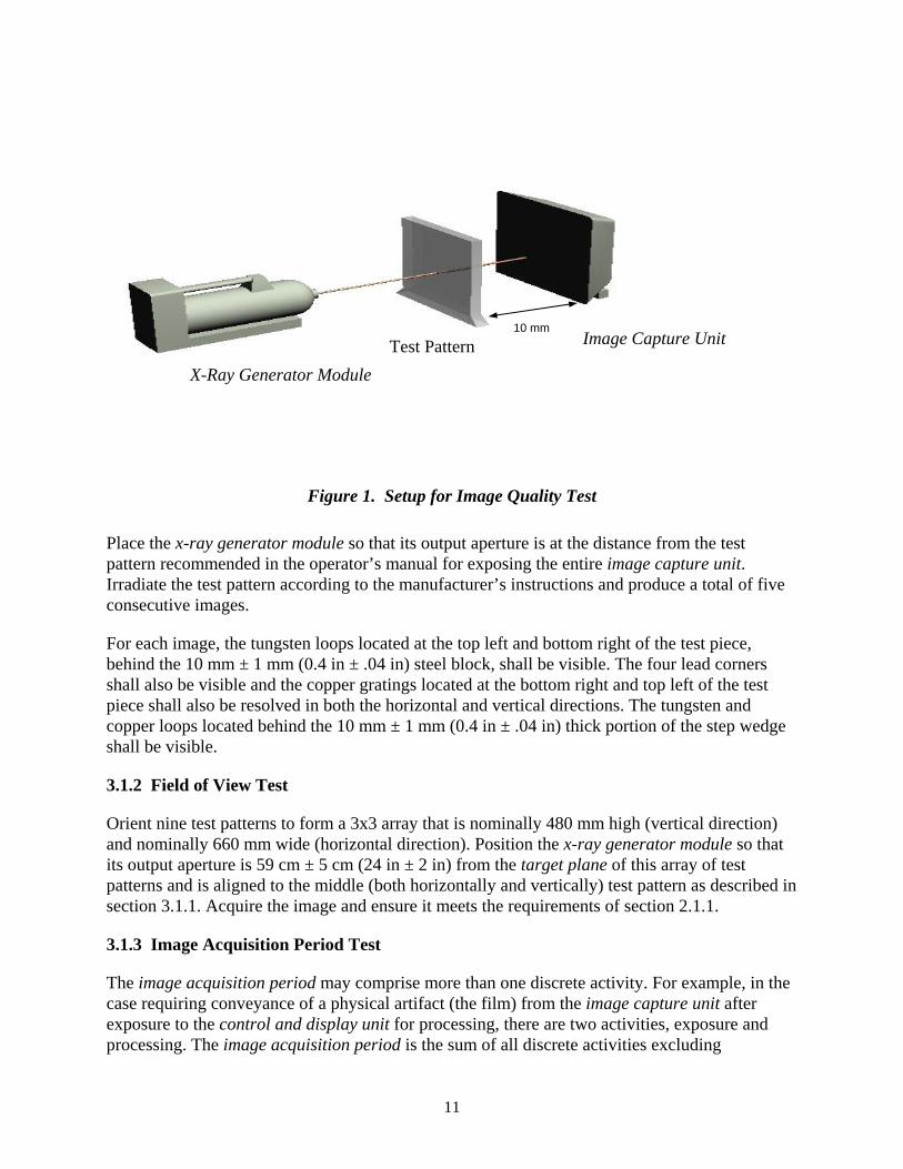
Using the test pattern shown in figures 3 and 4, place the test pattern 10 mm ± 3 mm (0.39 in ± 0.12 in) from the image capture unit, as shown in figure 1. The alignment of the center of the test pattern to the center of the image capture unit shall be within ± 2 mm horizontally and ± 2 mm vertically. The front surface of the image capture unit and the target plane shall be parallel within ± 2 º vertically and ± 2 º horizontally.
10
10 mm Image Capture UnitTest Pattern
X-Ray Generator Module
Figure 1. Setup for Image Quality Test
Place the x-ray generator module so that its output aperture is at the distance from the test pattern recommended in the operator’s manual for exposing the entire image capture unit. Irradiate the test pattern according to the manufacturer’s instructions and produce a total of five consecutive images.
For each image, the tungsten loops located at the top left and bottom right of the test piece, behind the 10 mm ± 1 mm (0.4 in ± .04 in) steel block, shall be visible. The four lead corners shall also be visible and the copper gratings located at the bottom right and top left of the test piece shall also be resolved in both the horizontal and vertical directions. The tungsten and copper loops located behind the 10 mm ± 1 mm (0.4 in ± .04 in) thick portion of the step wedge shall be visible.
3.1.2 Field of View Test
Orient nine test patterns to form a 3x3 array that is nominally 480 mm high (vertical direction) and nominally 660 mm wide (horizontal direction). Position the x-ray generator module so that its output aperture is 59 cm ± 5 cm (24 in ± 2 in) from the target plane of this array of test patterns and is aligned to the middle (both horizontally and vertically) test pattern as described in section 3.1.1. Acquire the image and ensure it meets the requirements of section 2.1.1.
3.1.3 Image Acquisition Period Test
The image acquisition period may comprise more than one discrete activity. For example, in the case requiring conveyance of a physical artifact (the film) from the image capture unit after exposure to the control and display unit for processing, there are two activities, exposure and processing. The image acquisition period is the sum of all discrete activities excluding
11
conveyance or preparation. The duration of each activity is determined by using either an external timer or clock.
3.1.3.1 Procedure
Reset the timer or record the time indicated on the clock and within 2 s start the activity. Record this time as t0,i, where i denotes the ith activity. If a timer is used, t0,i = 0. When this activity is completed, within 2 s record the elapsed time indicated on the timer or the time indicated on the clock. Record this time as tf,i. The image acquisition period is determined using:
N
t − t∑ ( f ,i 0 ,i ), i=1
where N is the number of activities.
3.1.4 Image Extent
Position the image capture unit, x-ray generator module, and test pattern so that x-rays passing through the test pattern will impinge on the image capture unit down to the surface on which it is placed. Test the image quality as specified in Sec. 3.1.1 and verify that the image quality is uniform to within 12 mm of the edge on which the image capture unit was placed to acquire the image.
3.2 System Requirements
3.2.1 Safety
3.2.1.1 Leakage Radiation Test
Warning: Due to the radiation hazard, this test should be performed by a qualified person who has the knowledge and training to safely measure ionizing radiation. Guidance relating to the competence of an individual to discharge the responsibilities of a qualified expert may be obtained from the American Board of Health Physics, the American Board of Radiology, or the American Board of Industrial Hygiene. In the United Kingdom this information may be obtained by contacting the National Radiological Protection Board (NRPB).
Before measurements are taken the radiation aperture shall be covered by a lead plate, at least 3 mm thick, to prevent radiation emanating from the focal point. The x-ray leakage test is performed by measuring the leakage dose rate at the following nine locations (see fig. 2) relative to the x-ray generator module axis (the axis passing through the x-ray generator module that is collinear with the useful x-ray beam):
1 m ± 5 mm (39 in ± 0.2 in) above, below, to the left, and to the right of the x-ray generator module axis, where each location is in the plane of the aperture ± 10 mm (± 0.4 in) and angularly separated from each other in the plane of the aperture by 90 º ± 10 °; 1 m ± 5 mm (39 in ± 0.2 in) above, below, to the left, and to the right of the x-ray generator module axis, where each location is in the plane of the anode ± 10 mm
12
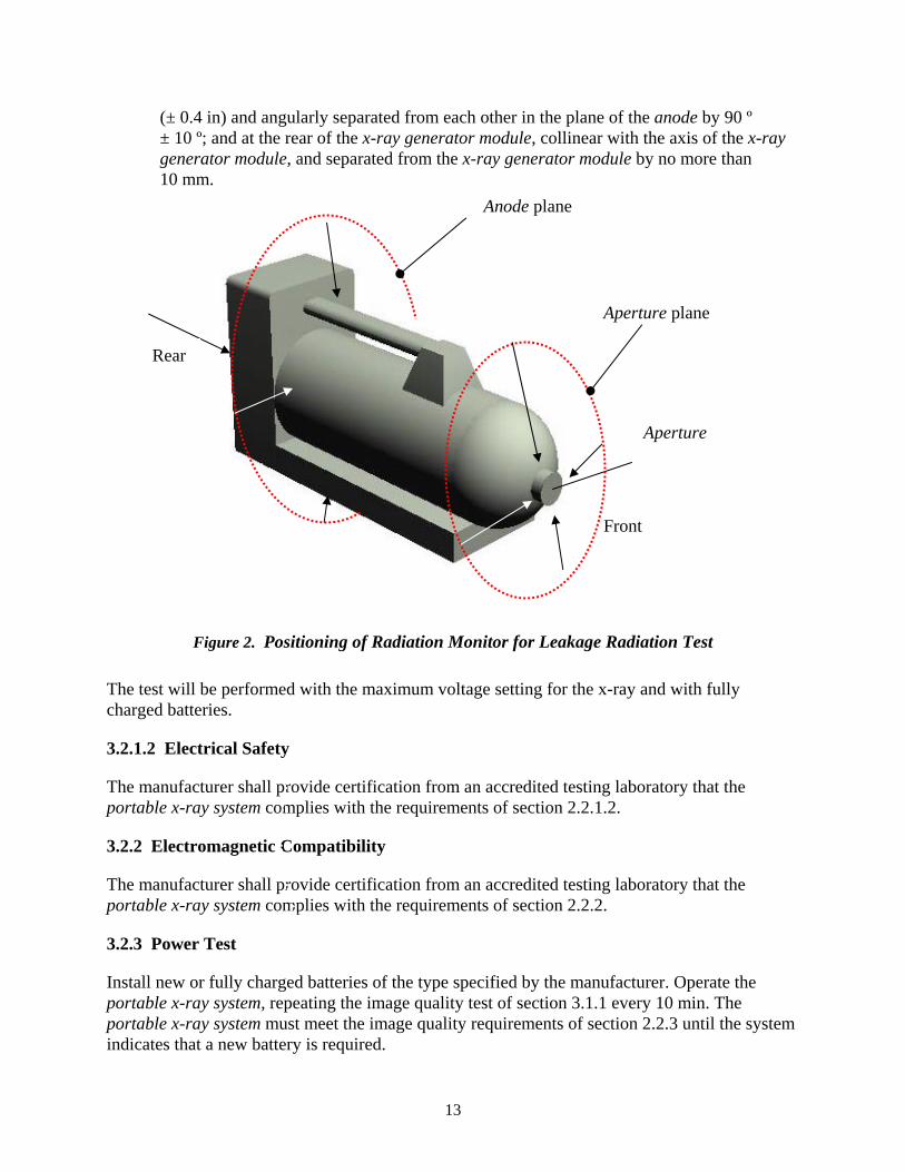
(± 0.4 in) and angularly separated from each other in the plane of the anode by 90 º ± 10 º; and at the rear of the x-ray generator module, collinear with the axis of the x-ray generator module, and separated from the x-ray generator module by no more than 10 mm.
Front
Aperture
Aperture plane
Anode plane
Rear
Figure 2. Positioning of Radiation Monitor for Leakage Radiation Test
The test will be performed with the maximum voltage setting for the x-ray and with fully charged batteries.
The manufacturer shall provide certification from an accredited testing laboratory that the portable x-ray system complies with the requirements of section 2.2.1.2.
The manufacturer shall provide certification from an accredited testing laboratory that the portable x-ray system complies with the requirements of section 2.2.2.
3.2.2 Electromagnetic Compatibility
3.2.1.2 Electrical Safety
3.2.3 Power Test
Install new or fully charged batteries of the type specified by the manufacturer. Operate the portable x-ray system, repeating the image quality test of section 3.1.1 every 10 min. The portable x-ray system must meet the image quality requirements of section 2.2.3 until the system indicates that a new battery is required.
13

For type II portable x-ray system capable of operating from AC supply, connect the system to the supply and perform the image quality test of section 3.1.1.
3.2.4 Ruggedness
The manufacturer shall provide certification from an accredited testing laboratory that the portable x-ray system complies with the requirements of section 2.2.4.
3.2.5 Environmental Requirements Tests
The manufacturer shall provide certification from an accredited testing laboratory that the portable x-ray system complies with the requirements of section 2.2.5.
3.2.6 Tripod Support
Attach x-ray generator module to a typical tripod support, ¼-20 UNC (¼ in BSW).
3.3 Operating Requirements
3.3.1 Remote Control and Viewing
Ensure that the activation device can be used at least 6 m (20 ft) from the generator.
3.3.2 Exposure
3.3.2.1 Exposure Control
Ensure that the interlocking key cannot be removed while the system is operating and producing x-rays.
3.3.2.2 Exposure Delay
Activate the portable x-ray system and delay the exposure time by 1 min.
3.3.3 Indicators
3.3.3.1 X-Ray Emission Warning Alarms
3.3.3.1.1 Audible Alarm
Perform the test in an anechoic chamber or at an outdoor location, at least 6 m (20 ft) from any large object, where the ambient sound pressure level at the time of the test is not more than 53 dBSPL. Position the sound pressure level (SPL) meter microphone 800 mm (31 in) from the x-ray generator module. Measure the sound pressure level when the x-ray generator module is in a state of readiness to emit radiation, when the radiation is about to be emitted, and when radiation is being emitted.
14

Position the generator with its visual alarm indicator at 6 m (20 ft) from an observer at a test site where the ambient illumination is 10,000 lux ± 1,000 lux. After allowing 3 min for eye accommodation, turn on the portable x-ray system and observe the alarm indication. Observe the visual alarm when the x-ray generator module is in a state of readiness to emit radiation, when the radiation is about to be emitted, and when radiation is being emitted.
3.3.3.2 Control Software
Operate the software and verify that it performs per specifications.
3.3.4 Portability
Weigh the individual components of the portable x-ray system including carrying cases.
3.3.5 Switch Size
Measure the size of the switch and verify that it is within specifications.
3.3.6 Power-On Delay
Connect the x-ray generator module to the control and display unit. Set the x-ray generator module to emit using the control and display unit. Turn the x-ray generator module power switch to on and either record the time the switch was activated as t0 or trigger a stopwatch to start counting. Note the time the x-ray generator module power indicator light is illuminated and either note this time as t1 or trigger the stopwatch to stop counting. The power-on delay is either computed as t1 - t0 or is read directly from the stopwatch.
3.4 Support Requirements
3.4.1 Manufacturer Provided Equipment
Verify that any adapters and unique test equipment have been provided by the manufacturer.
3.4.1.1 Battery Tester
Verify that the manufacturer has supplied a battery tester and that it is working properly by comparing its readings when testing a fully charged battery.
3.4.2 Manufacturer Provided Information
Review the instructions of and examine the markings on the controls of the portable x-ray system to verify that the controls operate as explained in the manual and consistent with their markings.
3.4.3 Manufacturer Labeling
While it is impossible for this test to be exhaustive, the test engineer shall look for:
15
3.3.3.1.2 Visual Alarm
(a) Controls that are unmarked or that are marked in a misleading way.

(b) Modes of operation that are not documented. (c) Misleading labels appearing in an alphanumeric display. (d) Lack of clarity in the manual, including possible typographical errors.
No misleading words are permitted on the control and display unit, or in the manual. If an undocumented mode can be accessed, such as an engineering test mode for instance, the resulting display shall be clearly different from the display in the normal operational mode.
3.4.4 Accessibility of X-Ray Generator Tube
If the generator tube is capable of being replaced in the field, remove it and replace it using manufacturer-recommended or supplied tools.
3.5 Standard Test Conditions
3.5.1 Standard Temperature
Unless specified otherwise, at the time of the tests, the ambient temperature shall be 20 °C ± 2 °C (68 °F ± 4 °F).
3.5.2 Standard Humidity
Unless specified otherwise, at the time of the tests, the relative humidity shall be between 30 % and 70 %.
3.5.3 Battery Charge
Before beginning a test sequence, install new or recently/fully recharged batteries where appropriate.
3.6 Test Equipment
3.6.1 Background Dose Meter
The meter shall be capable of measuring doses from 100 μSv to 1 Sv with an uncertainty of less than ± 10 % of the measured value. The useful energy response of the meter shall be commensurate with the energy output of the x-ray generator module.
The cross-sectional area of the detection sensitive volume shall not exceed 100 cm2 with no more than 10 cm in any linear dimension.
3.6.2 Test Pattern
The basis of the test pattern shall be a 220 mm x 160 mm x 6 mm sheet of acrylic, see figure 4. Affixed to this sheet shall be:
• 2 steel blocks of 30 mm x 30 mm x 10 mm.
16
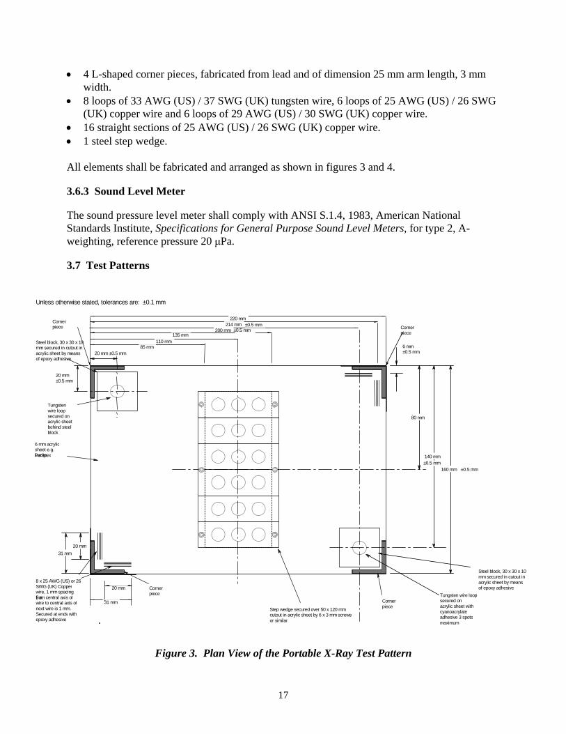
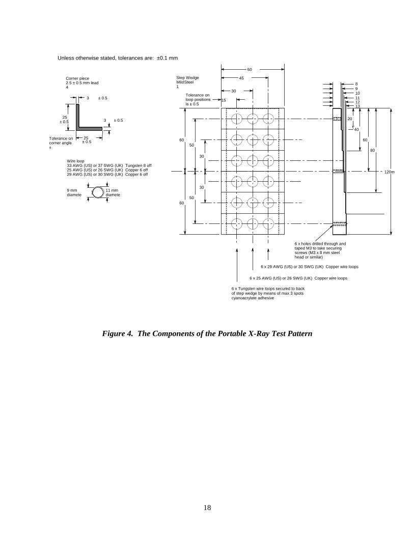
• 4 L-shaped corner pieces, fabricated from lead and of dimension 25 mm arm length, 3 mm width.
• 8 loops of 33 AWG (US) / 37 SWG (UK) tungsten wire, 6 loops of 25 AWG (US) / 26 SWG (UK) copper wire and 6 loops of 29 AWG (US) / 30 SWG (UK) copper wire.
• 16 straight sections of 25 AWG (US) / 26 SWG (UK) copper wire. • 1 steel step wedge.
All elements shall be fabricated and arranged as shown in figures 3 and 4.
3.6.3 Sound Level Meter
The sound pressure level meter shall comply with ANSI S.1.4, 1983, American National Standards Institute, Specifications for General Purpose Sound Level Meters, for type 2, A-weighting, reference pressure 20 μPa.
3.7 Test Patterns
Unless otherwise stated, tolerances are: ±0.1 mm
of epoxy adhesive
wire loop
block
6 mm acrylic sheet e.g. Lucite,Perspex
220 mm 214 mm
135 mm 110 mm
200 mm
160 mm
80 mm
140 mm
6 mm ±0.5 mm
±0.5 mm
20 mm ±0.5 mm
20 mm ±0.5 mm
±0.5 mm
8 x 25 AWG (US) or 26
31 mm 20 mm
31 mm
20 mm
Corner piece Corner
piece
Corner
Corner piece
Tungsten
secured on acrylic sheet behind steel
Tungsten wire loop secured on
85 mm Steel block, 30 x 30 x 10 mm secured in cutout in acrylic sheet by means
±0.5 mm
±0.5 mm
Steel block, 30 x 30 x 10 mm secured in cutout in acrylic sheet by means
SWG (UK) Copper of epoxy adhesive wire, 1 mm spacing (i.e. from central axis of wire to central axis of
piece acrylic sheet with next wire is 1 mm. Step wedge secured over 50 x 120 mm cyanoacrylate Secured at ends with cutout in acrylic sheet by 6 x 3 mm screws adhesive 3 spotsepoxy adhesive or similar maximum
Figure 3. Plan View of the Portable X-Ray Test Pattern
17
4
Unless otherwise stated, tolerances are: ±0.1 mm
Corner piece 2.5 ± 0.5 mm lead
3 ± 0.5
3 ± 0.5
Tolerance on corner angle
25
± 0.5
± 0.5 ±
25
Wire loop 33 AWG (US) or 37 SWG (UK) Tungsten 8 off 25 AWG (US) or 26 SWG (UK) Copper 6 off 29 AWG (US) or 30 SWG (UK) Copper 6 off
9 mm 11 mm diamete diamete
8 9 10 11 12 13
20
40
60
80
60
45
30 Tolerance on
15
60
60
50
50
30
30
loop positions is ± 0.5
Step Wedge Mild Steel 1
120m
6 x holes drilled through and taped M3 to take securing screws (M3 x 8 mm steel head or similar)
6 x 29 AWG (US) or 30 SWG (UK) Copper wire loops
6 x 25 AWG (US) or 26 SWG (UK) Copper wire loops
6 x Tungsten wire loops secured to back of step wedge by means of max 3 spots cyanoacrylate adhesive
Figure 4. The Components of the Portable X-Ray Test Pattern
18

4. REFERENCES
ANSI S.1.4, 1983, American National Standards Institute, Specifications for General Purposes Sound Level Meters.
CISPR 11, Industrial, Scientific and Medical (ISM) Radio-Frequency Equipment - Electromagnetic Disturbance Characteristics - Limits and Methods of Measurement.
IEC 60068–2–29, International Electrotechnical Commission, Basic Environmental Testing Procedures - Part 2: Tests - Test Eb and Guidance: Bump.
IEC 60068–2–32, International Electrotechnical Commission, Basic Environmental Testing Procedures - Part 2: Tests - Test Ed: Free Fall.
IEC 61000–4–2, International Electrotechnical Commission, Electromagnetic Compatibility (EMC) - Part 4: Testing and Measurement Techniques - Section 2: Electrostatic Discharge Immunity Test - Basic EMC Publication.
IEC 61000–4–3, International Electrotechnical Commission, Electromagnetic Compatibility (EMC) - Part 4: Testing and Measurement Techniques - Section 3: Radiated, Radio-Frequency, Electromagnetic Field Immunity Test.
IEC 61000–4–4, International Electrotechnical Commission, Electromagnetic Compatibility (EMC) - Part 4: Testing and Measurement Techniques - Section 4: Electrical Fast Transient/Burst Immunity Test - Basic EMC Publication.
IEC 61000–4–5, International Electrotechnical Commission, Electromagnetic Compatibility (EMC) - Part 4: Testing and Measurement Techniques - Section 5: Surge Immunity Test.
IEC 61000–4–6, International Electrotechnical Commission, Electromagnetic Compatibility (EMC) - Part 4: Testing and Measurement Techniques - Section 6: Immunity to Conducted Disturbances, Induced by Radio Frequency Fields.
IEC 61000–4–8, International Electrotechnical Commission, Electromagnetic Compatibility (EMC) - Part 4: Testing and Measurement Techniques - Section 8: Power Frequency Magnetic Field Immunity Test - Basic EMC Publication.
IEC 61000–4–11, International Electrotechnical Commission, Electromagnetic Compatibility (EMC) - Part 4: Testing and Measurement Techniques - Section 11: Voltage Dips, Short Interruptions and Voltage Variations Immunity Tests.
IEC 61000–6–1, International Electrotechnical Commission, Electromagnetic Compatibility (EMC) - Part 6–1: Generic Standards - Immunity for Residential, Commercial and Light-Industrial Environments.
IEC 60601–2–7, International Electrotechnical Commission, Medical Electrical Equipment -Part 2–7: Particular Requirements for the Safety of High-Voltage Generators of Diagnostic X-Ray Generators.
19

IEC 60601–2–28, International Electrotechnical Commission, Medical Electrical Equipment -Part 2: Particular Requirements for the Safety of X-Ray Source Assemblies and X-Ray Tube Assemblies for Medical Diagnosis.
IEC 61010–1, International Electrotechnical Commission, Safety Requirements for Electrical Equipment for Measurement, Control, and Laboratory Use - Part 1: General Requirements.
MIL–STD–810F Method 501.4, Military Standard, Test Method Standard for Environmental Engineering Considerations and Laboratory Tests, Method 501.4, High Temperature.
MIL–STD–810F Method 502.4, Military Standard, Test Method Standard for Environmental Engineering Considerations and Laboratory Tests, Method 502.4, Low Temperature.
MIL–STD–810F Method 507.4, Military Standard, Test Method Standard for Environmental Engineering Considerations and Laboratory Tests, Method 507.4, Humidity.
UL 61010A–1 Underwriters Laboratories, Electrical Equipment for Laboratory Use, Part: 1 General Requirements.
U.S. Nuclear Regulatory Commission, Title 10, Code of Federal Regulations, Section 20.1901.
U.S. Federal Communications Commission, Title 47, Code of Federal Regulations, Part 18.
20

About the Law Enforcement and Corrections Standards and Testing Program
The Law Enforcement and Corrections Standards and Testing Program is sponsored by the Office of Science and Technology of the National Institute of Justice (NIJ), U.S. Department of Justice. The program responds to the mandate of the Justice System Improvement Act of 1979, which directed NIJ to encourage research and development to improve the criminal justice system and to disseminate the results to Federal, State, and local agencies.
The Law Enforcement and Corrections Standards and Testing Program is an applied research effort that determines the technological needs of justice system agencies, sets minimum performance standards for specific devices, tests commercially available equipment against those standards, and disseminates the standards and the test results to criminal justice agencies nationally and internationally.
The program operates through:
The Law Enforcement and Corrections Technology Advisory Council (LECTAC), consisting of nationally recognized criminal justice practitioners from Federal, State, and local agencies, which assesses technological needs and sets priorities for research programs and items to be evaluated and tested.
The Office of Law Enforcement Standards (OLES) at the National Institute of Standards and Technology, which develops voluntary national performance standards for compliance testing to ensure that individual items of equipment are suitable for use by criminal justice agencies. The standards are based upon laboratory testing and evaluation of representative samples of each item of equipment to determine the key attributes, develop test methods, and establish minimum performance requirements for each essential attribute. In addition to the highly technical standards, OLES also produces technical reports and user guidelines that explain in nontechnical terms the capabilities of available equipment.
The National Law Enforcement and Corrections Technology Center (NLECTC), operated by a grantee, which supervises a national compliance testing program conducted by independent laboratories. The standards developed by OLES serve as performance benchmarks against which commercial equipment is measured. The facilities, personnel, and testing capabilities of the independent laboratories are evaluated by OLES prior to testing each item of equipment, and OLES helps the NLECTC staff review and analyze data. Test results are published in Equipment Performance Reports designed to help justice system procurement officials make informed purchasing decisions.
Publications are available at no charge through the National Law Enforcement and Corrections Technology Center. Some documents are also available online through the Internet/World Wide Web. To request a document or additional information, call 800–248–2742 or 301–519–5060, or write:
National Law Enforcement and Corrections Technology Center 2277 Research Boulevard, Mail Stop 8J Rockville, MD 20850 E-Mail: [email protected] World Wide Web address: http://www.nlectc.org
This document is not intended to create, does not create, and may not be relied upon to create any rights, substantive or procedural, enforceable at law by any party in any matter civil or criminal.
Opinions or points of view expressed in this document represent a consensus of the authors and do not represent the official position or policies of the U.S. Department of Justice. The products and manufacturers discussed in this document are presented for informational purposes only and do not constitute product approval or endorsement by the U.S. Department of Justice.
The National Institute of Justice is a component of the Office of Justice Programs, which also includes the Bureau of Justice Assistance; the Bureau of Justice Statistics; the Community Capacity Development Office; the Office for Victims of Crime; the Office of Juvenile Justice and Delinquency Prevention; and the Office of Sex Offender Sentencing, Monitoring, Apprehending, Registering, and Tracking (SMART).