Embed Size (px)
Citation preview
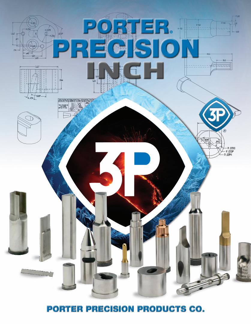
PORTER PRECISION PRODUCTS CO.
PORTERPRECISION
®
INCH
BD BDW GL GD GU
SAPQ SAPN PAPQ PAPN
2© 2017 — Porter Precision Products Company
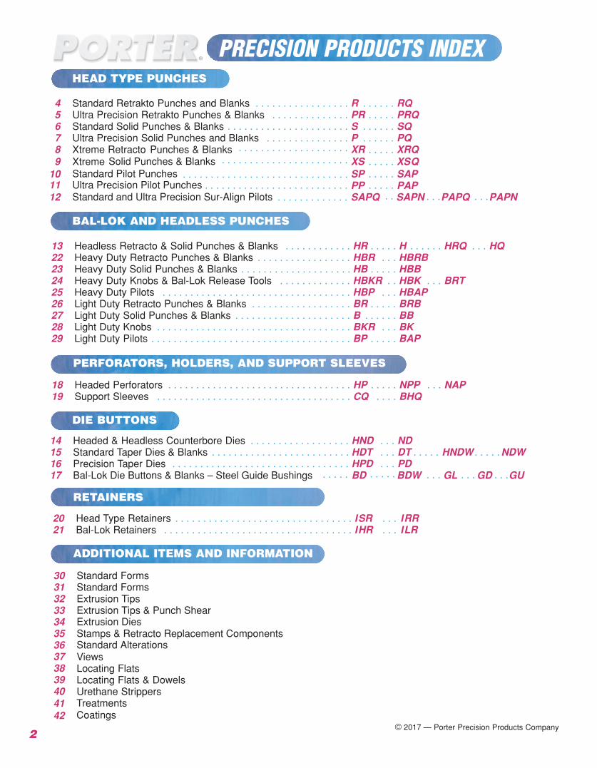
4 Standard Retrakto Punches and Blanks . . . . . . . . . . . . . . . . . R . . . . . . RQ5 Ultra Precision Retrakto Punches & Blanks . . . . . . . . . . . . . . PR . . . . . PRQ6 Standard Solid Punches & Blanks . . . . . . . . . . . . . . . . . . . . . .
. . . . . . . . . . . . . . . . . . . .
S . . . . . . SQ7 Ultra Precision S
Solid Punches & Blanks
olid Punches and Blanks . . . . . . . . . . . . . . . P . . . . . . PQ
9 Xtreme XS . . . . . XSQ8 Xtreme Retracto Punches & Blanks XR . . . . . XRQ
. .
Standard Pilot Punches
Standard and Ultra Precision Sur-Align PilotsUltra Precision Pilot Punches
. . . . . . . . . . . . . . . . . . . . . . . SP . . . . .
. . . . .SAP10
11 PP PAP12 . . . . . . . . . . . . .
. . . . . . . . . . . . . . . . . . . . . . . . . . . . . . . . . . . . . . . . . . . . . . . . . . . . . . . .
. . . . . .
13 Headless Retracto & Solid Punches & Blanks . . . . . . . . . . . . HR . . . . . H . . . . . . HRQ . . . HQ22 Heavy Duty Retracto Punches & Blanks . . . . . . . . . . . . . . . . . HBR . . . HBRB23 Heavy Duty Solid Punches & Blanks . . . . . . . . . . . . . . . . . . . . HB . . . . . HBB24 Heavy Duty Knobs & Bal-Lok Release Tools . . . . . . . . . . . . . HBKR . . HBK . . . BRT25 Heavy Duty Pilots . . . . . . . . . . . . . . . . . . . . . . . . . . . . . . . . . . HBP . . . HBAP26 Light Duty Retracto Punches & Blanks . . . . . . . . . . . . . . . . . . BR . . . . . BRB27 Light Duty Solid Punches & Blanks . . . . . . . . . . . . . . . . . . . . . B . . . . . . BB28 Light Duty Knobs . . . . . . . . . . . . . . . . . . . . . . . . . . . . . . . . . . . BKR . . . BK29 Light Duty Pilots . . . . . . . . . . . . . . . . . . . . . . . . . . . . . . . . . . . . BP . . . . . BAP
18 Headed Perforators . . . . . . . . . . . . . . . . . . . . . . . . . . . . . . . . . HP . . . . . NPP . . . NAP19 Support Sleeves . . . . . . . . . . . . . . . . . . . . . . . . . . . . . . . . . . . CQ . . . . BHQ
14 Headed & Headless Counterbore Dies . . . . . . . . . . . . . . . . . . HND . . . ND15 Standard Taper Dies & Blanks . . . . . . . . . . . . . . . . . . . . . . . . . HDT . . . . . . . .
. . . . . . . . . .
. . . . .D HNDW NDWT16 Precision Taper Dies . . . . . . . . . . . . . . . . . . . . . . . . . . . . . . . . HPD . . .
. . . . . . . . .PD
17 Bal-Lok Die Buttons & Blanks – Steel Guide Bushings
20 Head Type Retainers . . . . . . . . . . . . . . . . . . . . . . . . . . . . . . . . ISR . . . IRR21 Bal-Lok Retainers . . . . . . . . . . . . . . . . . . . . . . . . . . . . . . . . . . IHR . . . ILR
30 Standard Forms31 Standard Forms32 Extrusion Tips33 Extrusion Tips & Punch Shear
Extrusion Dies3435 Stamps & Retracto Replacement Components
Standard Alterations36Views37Locating Flats38Locating Flats & Dowels39Urethane Strippers40
4142
TCoatings
reatments
BAL-LOK AND HEADLESS PUNCHES
PERFORATORS, HOLDERS, AND SUPPORT SLEEVES
DIE BUTTONS
RETAINERS
ADDITIONAL ITEMS AND INFORMATION
PRECISION PRODUCTS INDEXHEAD TYPE PUNCHES
3
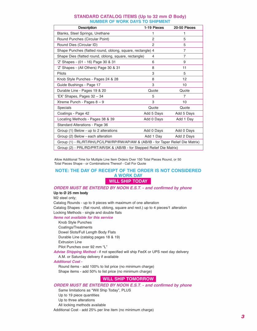
Description 1-19 Pieces 20-50 PiecesBlanks, Steel Springs, Urethane 1 1Round Punches (Circular Point) 2 5Round Dies (Circular ID) 2 5Shape Punches (flatted round, oblong, square, rectangle) 4 7Shape Dies (flatted round, oblong, square, rectangle) 4 7‘Z' Shapes - (01 - 16) Page 30 & 31 6 9‘Z' Shapes - (All Others) Page 30 & 31 8 11Pilots 3 5Knob Style Punches - Pages 24 & 28 8 12Guide Bushings - Page 17 3 10Durable Line - Pages 19 & 20 Quote Quote‘EX' Shapes, Pages 32 – 34 5 7Xtreme Punch - Pages 8 – 9 3 10Specials Quote QuoteCoatings - Page 42 Add 5 Days Add 5 DaysLocating Methods - Pages 38 & 39 Add 0 Days Add 1 DayStandard Alterations - Page 36Group (1) Below - up to 2 alterations Add 0 Days Add 0 DaysGroup (2) Below - each alteration Add 1 Day Add 2 DaysGroup (1) - RL/RT/RH/LPC/LPW/RP/RW/AP/AW & (AB/IB - for Taper Relief Die Matrix)Group (2) - PRL/RD/PRT/AR/SK & (AB/IB - for Stepped Relief Die Matrix)
STANDARD CATALOG ITEMS (Up to 32 mm Ø Body)NUMBER OF WORK DAYS TO SHIPMENT
Allow Additional Time for Multiple Line Item Orders Over 150 Total Pieces Round, or 50 Total Pieces Shape - or Combinations Thereof - Call For Quote
NOTE: THE DAY OF RECEIPT OF THE ORDER IS NOT CONSIDEREDA WORK DAY
WILL SHIP TODAYORDER MUST BE ENTERED BY NOON E.S.T. - and confirmed by phoneUp to Ø 25 mm bodyM2 steel only;Catalog Rounds - up to 9 pieces with maximum of one alteration Catalog Shapes - (flat round, oblong, square and rect.) up to 4 pieces/1 alterationLocking Methods - single and double flatsItems not available for this service
Knob Style PunchesCoatings/TreatmentsDowel Slots/Full Length Body FlatsDurable Line (catalog pages 18 & 19)Extrusion LinePilot Punches over 92 mm “L”
Advise Shipping Method - if not specified will ship FedX or UPS next day delivery A.M. or Saturday delivery if available
Additional Cost -Round items - add 100% to list price (no minimum charge)Shape items - add 50% to list price (no minimum charge)
WILL SHIP TOMORROWORDER MUST BE ENTERED BY NOON E.S.T. - and confirmed by phone
Same limitations as “Will Ship Today”, PLUSUp to 19 piece quantitiesUp to three alterations All locking methods available
Additional Cost - add 25% per line item (no minimum charge)
4
2
Standard Alterations are changes that are beyond the ranges listed inthe catalog that can be altered for a minimal charge. See page 36.
*Ejector
Ejector
Kits available see page 35 for details. D2 up to 1.00 Ø 4.00 long Punches .1875 and 1.25 and larger = No side hole.
Punches ≤ 2.00L or > 4.00L = No side hole.
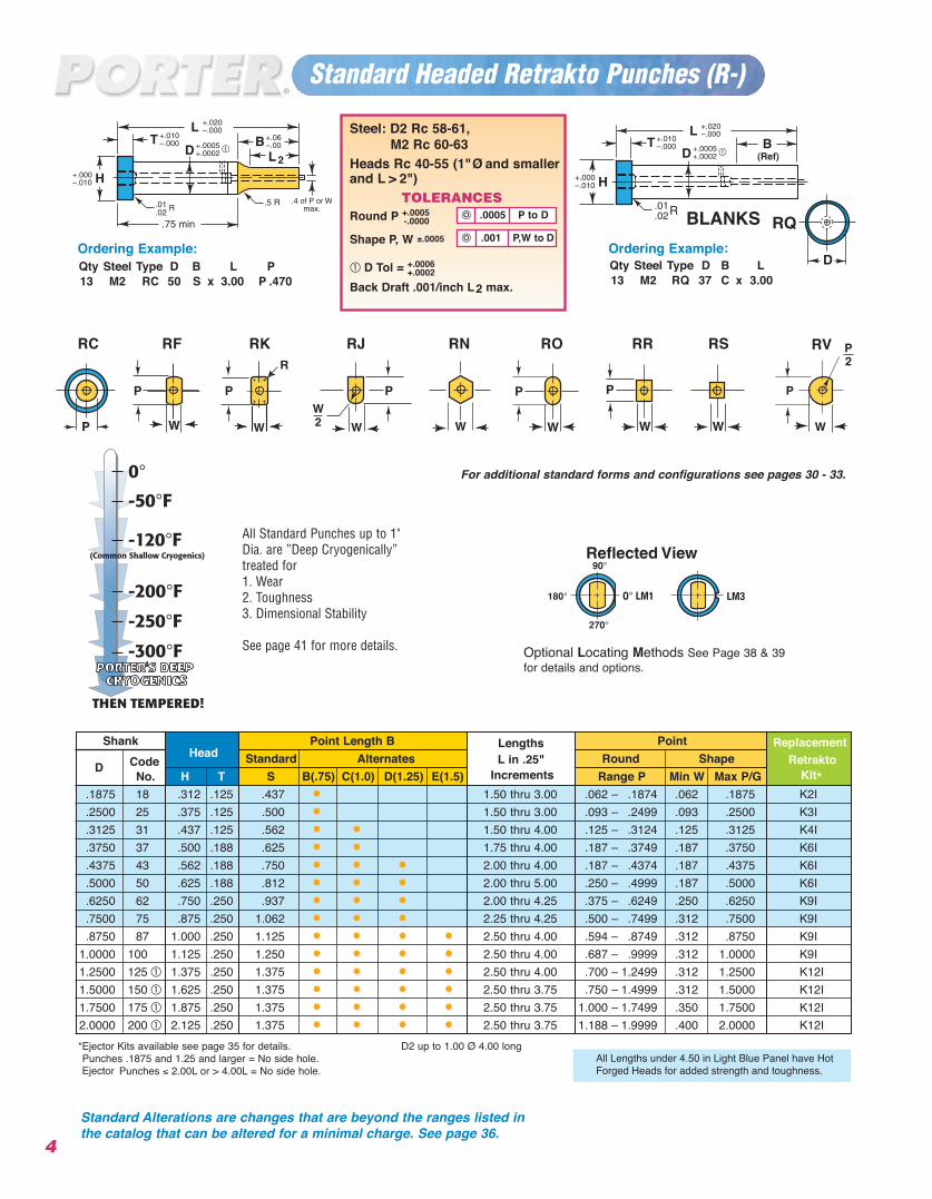
Ordering Example: Qty Steel Type D B L P13 M2 RC 50 S x 3.00 P .470
Ordering Example:Qty Steel Type D B L13 M2 RQ 37 C x 3.00
R
H+.000–.010
Steel: D2 Rc 58-61,M2 Rc 60-63
Heads Rc 40-55 (1" Ø and smallerand L > 2")
TOLERANCESRound P +.0005
-.0000
Shape P, W ±.0005
D Tol = +.0006+.0002
Back Draft .001/inch L2 max.
.001 P,W to D
.0005 P to D
Standard Headed Retrakto Punches (R-)
Shank Point Length B Lengths Point ReplacementCode
Head Standard Alternates L in .25" Round Shape RetraktoDNo. H T S B(.75) C(1.0) D(1.25) E(1.5) Increments Range P Min W Max P/G Kit*
.1875 18 .312 .125 .437 • 1.50 thru 3.00 .062 – .1874 .062 .1875 K2I
.2500 25 .375 .125 .500 • 1.50 thru 3.00 .093 – .2499 .093 .2500 K3I
.3125 31 .437 .125 .562 • • 1.50 thru 4.00 .125 – .3124 .125 .3125 K4I
.3750 37 .500 .188 .625 • • 1.75 thru 4.00 .187 – .3749 .187 .3750 K6I
.4375 43 .562 .188 .750 • • • 2.00 thru 4.00 .187 – .4374 .187 .4375 K6I
.5000 50 .625 .188 .812 • • • 2.00 thru 5.00 .250 – .4999 .187 .5000 K6I
.6250 62 .750 .250 .937 • • • 2.00 thru 4.25 .375 – .6249 .250 .6250 K9I
.7500 75 .875 .250 1.062 • • • 2.25 thru 4.25 .500 – .7499 .312 .7500 K9I
.8750 87 1.000 .250 1.125 • • • • 2.50 thru 4.00 .594 – .8749 .312 .8750 K9I1.0000 100 1.125 .250 1.250 • • • • 2.50 thru 4.00 .687 – .9999 .312 1.0000 K9I1.2500 125 1.375 .250 1.375 • • • • 2.50 thru 4.00 .700 – 1.2499 .312 1.2500 K12I1.5000 150 1.625 .250 1.375 • • • • 2.50 thru 3.75 .750 – 1.4999 .312 1.5000 K12I1.7500 175 1.875 .250 1.375 • • • • 2.50 thru 3.75 1.000 – 1.7499 .350 1.7500 K12I2.0000 200 2.125 .250 1.375 • • • • 2.50 thru 3.75 1.188 – 1.9999 .400 2.0000 K12I
All Standard Punches up to 1"Dia. are ”Deep Cryogenically”treated for 1. Wear2. Toughness3. Dimensional Stability
See page 41 for more details.
BLANKS
Optional Locating Methods See Page 38 & 39for details and options.
For additional standard forms and configurations see pages 30 - 33.
RKRF RJ RN RO RR RS RVRC
All Lengths under 4.50 in Light Blue Panel have HotForged Heads for added strength and toughness.
2
R
H+.000–.010
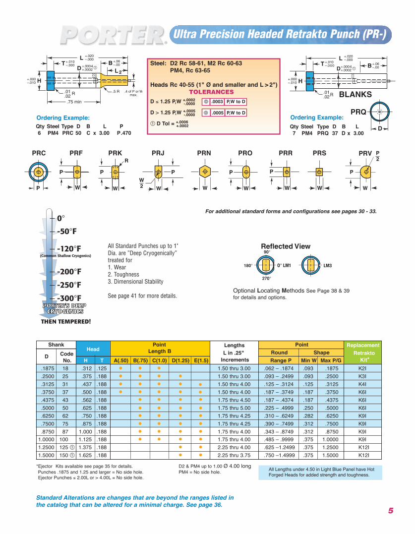
Ordering Example:Qty Steel Type D B L7 PM4 PRQ 37 D x 3.00
Ordering Example:Qty Steel Type D B L P6 PM4 PRC 50 C x 3.00 P.470
Shank Point Lengths Point ReplacementCode
Head Length B L in .25" Round Shape RetraktoDNo. H T A(.50) B(.75) C(1.0) D(1.25) E(1.5) Increments Range P Min W Max P/G Kit*
.1875 18 .312 .125 • • • 1.50 thru 3.00 .062 – .1874 .093 .1875 K2I
.2500 25 .375 .188 • • • • 1.50 thru 3.00 .093 – .2499 .093 .2500 K3I
.3125 31 .437 .188 • • • • 1.50 thru 4.00 .125 – .3124 .125 .3125 K4I
.3750 37 .500 .188 • • • • 1.50 thru 4.00 .187 – .3749 .187 .3750 K6I
.4375 43 .562 .188 1.75 thru 4.50 .187 – .4374 .187 .4375 K6I
.5000 50 .625 .188 1.75 thru 5.00 .225 – .4999 .250 .5000 K6I
.6250 62 .750 .188 1.75 thru 4.25 .310 – .6249 .282 .6250 K9I
88.7500 75 .875 .1 8 1.75 thru 4.25 .390 – .7499 .312 .7500 K9I
.8750 87 1.000 .1 8 1.75 thru 4.00 .343 – .8749 .312 .8750 K9I1.0000 100 1.125 .188 • • • •
• • • •• • • •• • • •• • • •• • • •
1.75 thru 4.00 .485 – .9999 .375 1.0000 K9I1.2500 125 1.375 .188 • • 2.25 thru 4.00 .625 –1.2499 .375 1.2500 K12I1.5000 150 1.625 .188 • • 2.25 thru 3.75 .750 –1.4999 .375 1.5000 K12I
*Ejector
Ejector
Kits available see page 35 for details. D2 & PM4 up to 1.00 Ø 4.00 long Punches .1875 and 1.25 and larger = No side hole. PM4 = No side hole.
Punches ≤ 2.00L or > 4.00L = No side hole.
Ultra Precision Headed Retrakto Punch (PR-)
5
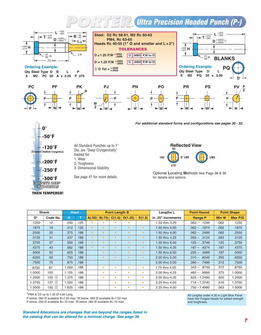
Steel: D2 Rc 58-61, M2 Rc 60-63PM4, Rc 63-65
Heads Rc 40-55 (1" Ø and smaller and L > 2")TOLERANCES
D ≤ 1.25 P,W +.0002-.0000
D > 1.25 P,W +.0005-.0000
D Tol = +.0006+.0002
.0005 P,W to D
.0003 P,W to DBLANKS
Standard Alterations are changes that are beyond the ranges listed inthe catalog that can be altered for a minimal charge. See page 36.
All Standard Punches up to 1"Dia. are ”Deep Cryogenically”treated for 1. Wear2. Toughness3. Dimensional Stability
See page 41 for more details.Optional Locating Methods See Page 38 & 39for details and options.
For additional standard forms and configurations see pages 30 - 33.
PRKPRF PRJ PRN PRO PRR PRS PRVPRC
All Lengths under 4.50 in Light Blue Panel have HotForged Heads for added strength and toughness.
••
*D2 up to 1.00 Ø 4.00 Long All Lengths under 4.50 in Light Blue Panel have HotForged Heads for added strength and toughness.
2
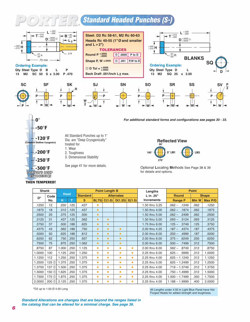
Ordering Example:Qty Steel Type D B L P13 M2 SC 50 S x 3.00 P .470
H+.000–.010
R
Ordering Example:Qty Steel Type D L13 M2 SQ 25 x 2.00
Steel: D2 Rc 58-61, M2 Rc 60-63Heads Rc 40-55 (1" Ø and smallerand L > 2")
TOLERANCESRound P +.0005
-.0000
Shape P, W ±.0005
D Tol = +.0006+.0002
Back Draft .001/inch L2 max.
.001 P,W to D
.0005 P to D
Standard Headed Punches (S-)
Shank Point Length B Lengths PointCode
Head Standard Alternates L in .25" Round ShapeD*
No. H T S B(.75) C(1.0) D(1.25) E(1.5) Increments Range P Min W Max P/G.1250 12 .250 .125 .437 • 1.50 thru 3.25 .062 – .1249 .062 .1250.1875 18 .312 .125 .437 • 1.50 thru 4.00 .062 – .1874 .062 .1875.2500 25 .375 .125 .500 • 1.50 thru 5.00 .062 – .2499 .062 .2500.3125 31 .437 .125 .562 • • 1.50 thru 5.00 .093 – .3124 .093 .3125.3750 37 .500 .188 .625 • • 1.75 thru 6.00 .125 – .3749 .125 .3750.4375 43 .562 .188 .750 • • • 2.00 thru 4.25 .187 – .4374 .187 .4375.5000 50 .625 .188 .812 • • • 2.00 thru 6.00 .250 – .4999 .187 .5000.6250 62 .750 .250 .937 • • • 2.00 thru 6.00 .375 – .6249 .250 .6250.7500 75 .875 .250 1.062 • • • 2.00 thru 6.00 .500 – .7499 .312 .7500.8750 87 1.000 .250 1.125 • • • • 2.00 thru 6.00 .562 – .8749 .312 .8750
1.0000 100 1.125 .250 1.250 • • • • 2.25 thru 6.00 .625 – .9999 .312 1.00001.1250 112 1.250 .250 1.375 • • • • 2.25 thru 4.00 .625 – 1.1249 .312 1.12501.2500 125 1.375 .250 1.375 • • • • 2.25 thru 5.00 .625 – 1.2499 .312 1.25001.3750 137 1.500 .250 1.375 • • • • 2.25 thru 4.00 .719 – 1.3749 .312 1.37501.5000 150 1.625 .250 1.375 • • • • 2.25 thru 4.00 .750 – 1.4999 .312 1.50001.7500 175 1.875 .250 1.375 • • • • 2.25 thru 4.00 1.000 – 1.7499 .350 1.75002.0000 200 2.125 .250 1.375 • • • • 2.25 thru 4.00 1.188 – 1.9999 .400 2.0000
6
BLANKS
All Standard Punches up to 1"Dia. are ”Deep Cryogenically”treated for 1. Wear2. Toughness3. Dimensional Stability
See page 41 for more details. Optional Locating Methods See Page 38 & 39for details and options.
For additional standard forms and configurations see pages 30 - 33.
SKSF SJ SN SO SR SS SVSC
Standard Alterations are changes that are beyond the ranges listed inthe catalog that can be altered for a minimal charge. See page 36.
Steel: D2 Rc 58-61, M2 Rc 60-63PM4, Rc 63-65
Heads Rc 40-55 (1" Ø and smaller and L > 2")TOLERANCES
D ≤≤1.25 P,W +.0002-.0000
D > 1.25 P,W +.0005-.0000
D Tol = +.0006+.0002
7
Ultra Precision Headed Punch (P-)
Shank Head Point Length B Lengths L Point Round Point ShapeD* Code No. H T A(.50) B(.75) C(1.0) D(1.25) E(1.5) in .25" Increments Range P Min W Max P/G
.1250 12 .250 .125 • • • • 1.50 thru 3.25 .062 – .1249 .062 .1250
.1875 18 .312 .125 • • • • • 1.50 thru 4.00 .062 – .1874 .062 .1875
.2500 25 .375 .188 • • • • • 1.50 thru 4.00 .062 – .2499 .062 .2500
.3125 31 .437 .188 • • • • • 1.50 thru 4.25 .093 – .3124 .093 .3125
.3750 37 .500 .188 • • • • • 1.50 thru 6.00 .125 – .3749 .125 .3750
.4375 43 .562 .188 • • • • • 1.50 thru 4.25 .187 – .4374 .187 .4375
.5000 50 .625 .188 • • • • 1.50 thru 6.00 .225 – .4999 .187 .5000
.6250 62 .750 .188 • • • • 2.00 thru 5.00 .310 – .6249 .250 .6250
.7500 75 .875 .188 2.00 thru 5.00 .390 – .7499 .312 .7500
1.0000 100 1.125 .188 • • • •• • • •
2.00 thru 4.25 .485 – .9999 .375 1.00001.2500 125 1.375 .188 • • • • 2.00 thru 4.25 .625 –1.2490 .500 1.25001.3750 137 1.500 .188 • • • 2.25 thru 4.00 .719 –1.3740 .516 1.37501.5000 150 1.625 .188 • • • 2.25 thru 4.00 .750 –1.4990 .563 1.5000
All Lengths under 4.50 in Light Blue Panelhave Hot Forged Heads for added strengthand toughness.
*PM4 & D2 up to 1.00 Ø 4.00 Long.P below .060 Ø available B=1.00 max W below .093 Ø available B=1.00 maxP below .050 Ø available B=.75 max W below .060 Ø available B=.75 max
H+.000–.010
Ordering Example:Qty Steel Type D L6 M2 PQ 50 x 3.00
Ordering Example:Qty Steel Type D B L P6 M2 PC 50 A x 3.25 P .375
H+.000–.010
2
.0005 P,W to D
.0003 P,W to DBLANKS
8.8750 87 1.000 .1 8 1.75 thru 4.00 .343 – .8749 .312 .8750
Standard Alterations are changes that are beyond the ranges listed inthe catalog that can be altered for a minimal charge. See page 36.
All Standard Punches up to 1"Dia. are ”Deep Cryogenically”treated for 1. Wear2. Toughness3. Dimensional Stability
See page 41 for more details.Optional Locating Methods See Page 38 & 39for details and options.
For additional standard forms and configurations see pages 30 - 33.
PKPF PJ PN PO PR PS PVPC
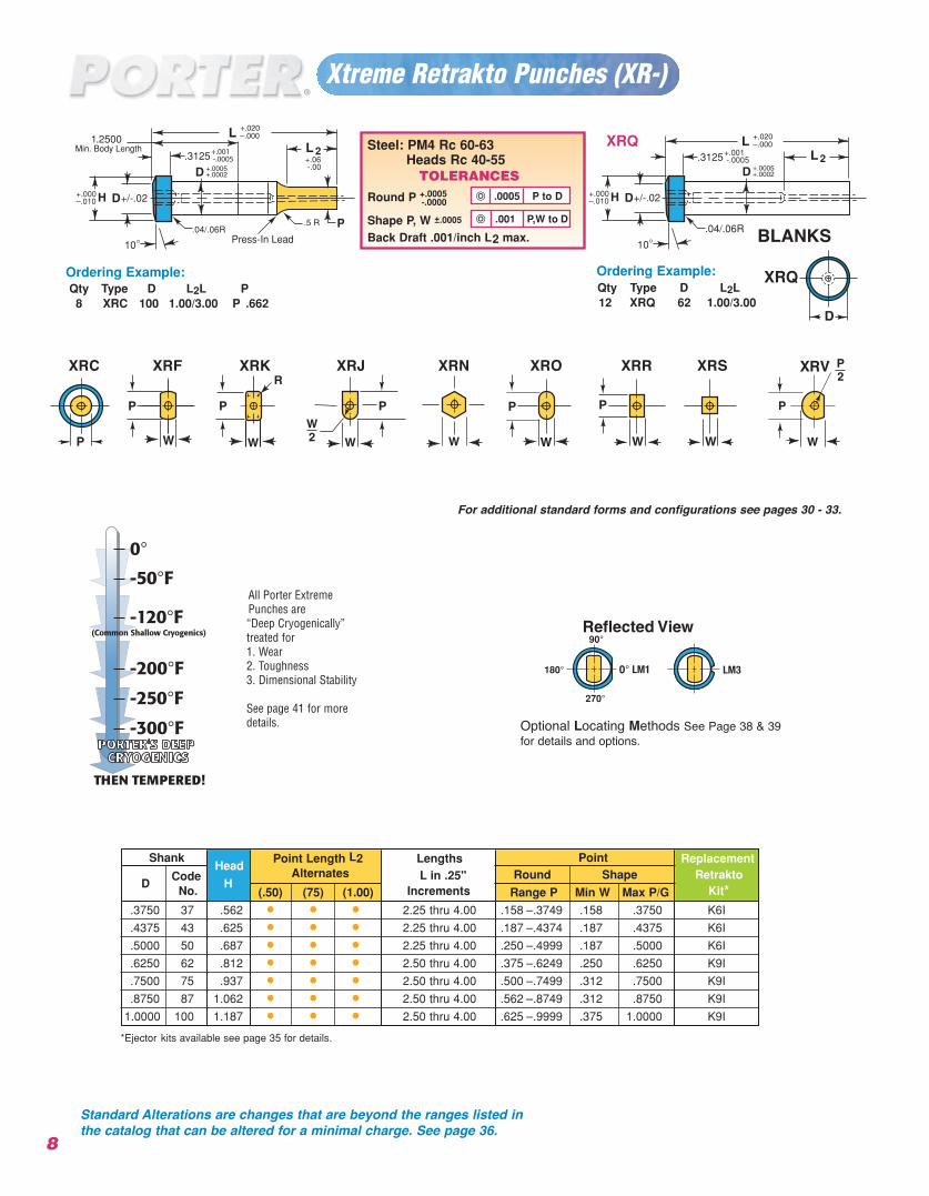
Xtreme Retrakto Punches (XR-)
Ordering Example: Qty Type D L2L P8 XRC 100 1.00/3.00 P .662
H+.000–.010
10°.04/.06R
.3125
+/-.02
+.001 -.0005 2
H+.000–.010
10°.04/.06R
.3125
+/-.02
+.06 -.00
+.001 -.0005
.25001Min. Body Length
Press-In Lead
P
2 Steel: PM4 Rc 60-63Heads Rc 40-55
TOLERANCESRound P +.0005
-.0000
Shape P, W ±.0005
Back Draft .001/inch L2 max.
.001 P,W to D
.0005 P to D
XRQ
Ordering Example:Qty Type D L2L12 XRQ 62 1.00/3.00
ShankHead
Point Length L2 Lengths Point Replacement
Code Alternates L in .25" Round Shape RetraktoD
No.H
(.50) (75) (1.00) Increments Range P Min W Max P/G Kit*
.3750 37 .562 • • • 2.25 thru 4.00 .158 –.3749 .158 .3750 K6I
.4375 43 .625 • • • 2.25 thru 4.00 .187 –.4374 .187 .4375 K6I
.5000 50 .687 • • • 2.25 thru 4.00 .250 –.4999 .187 .5000 K6I
.6250 62 .812 • • • 2.50 thru 4.00 .375 –.6249 .250 .6250 K9I
.7500 75 .937 • • • 2.50 thru 4.00 .500 –.7499 .312 .7500 K9I
.8750 87 1.062 • • • 2.50 thru 4.00 .562 –.8749 .312 .8750 K9I
1.0000 100 1.187 • • • 2.50 thru 4.00 .625 –.9999 .375 1.0000 K9I
*Ejector kits available see page 35 for details.
XRQ
8
Optional Locating Methods See Page 38 & 39for details and options.
For additional standard forms and configurations see pages 30 - 33.
BLANKS
Standard Alterations are changes that are beyond the ranges listed inthe catalog that can be altered for a minimal charge. See page 36.
All Porter ExtremePunches are “Deep Cryogenically”treated for 1. Wear2. Toughness3. Dimensional Stability
See page 41 for moredetails.
XRKXRF XRJ XRN XRO XRR XRS XRVXRC
9
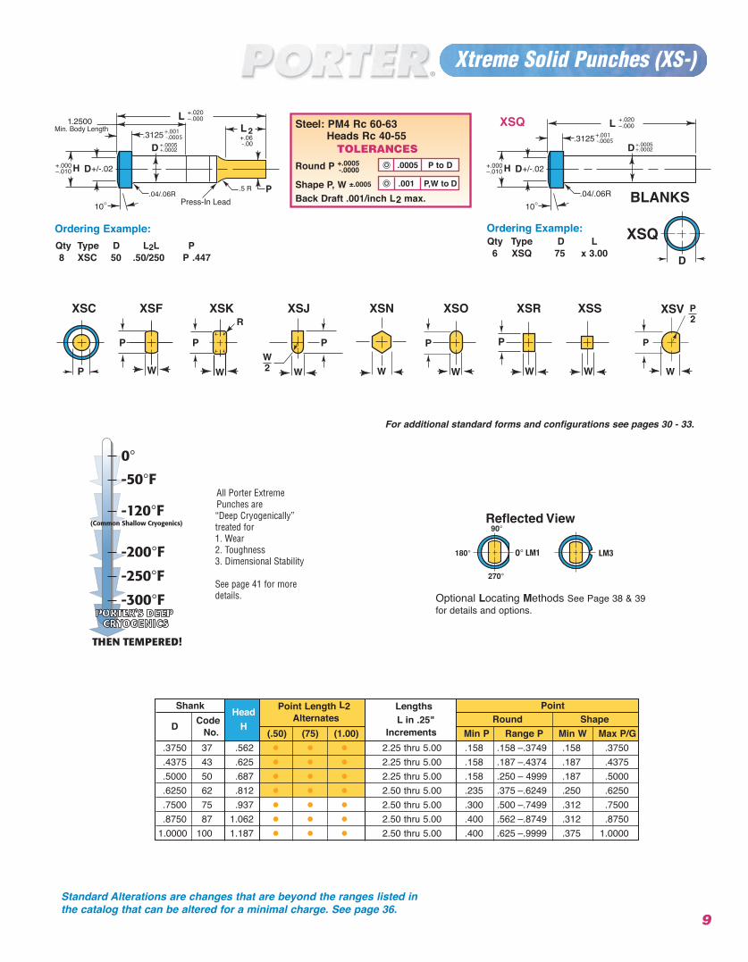
Xtreme Solid Punches (XS-)
Ordering Example: Qty Type D L6 XSQ 75 x 3.00
H+.000–.010
10°.04/.06R
.3125
+/-.02
+.001 -.0005
H+.000–.010
10°.04/.06R
.3125
+/-.02
+.06 -.00
+.001 -.0005
.25001Min. Body Length
Press-In LeadP
2Steel: PM4 Rc 60-63
Heads Rc 40-55 TOLERANCES
Round P +.0005-.0000
Shape P, W ±.0005
Back Draft .001/inch L2 max..001 P,W to D
.0005 P to D
XSQ
Ordering Example:Qty Type D L2L P8 XSC 50 .50/250 P .447
XSQ
Shank Head Point Length L2 Lengths PointCode Alternates L in .25" Round Shape
D No. H(.50) (75) (1.00) Increments Min P Range P Min W Max P/G
.3750 37 .562 • • • 2.25 thru 5.00 .158 .158 – .3749 .158 .3750
.4375 43 .625 • • • 2.25 thru 5.00 .158 .187 –.4374 .187 .4375
.5000 50 .687 • • • 2.25 thru 5.00 .158 .250 – 4999 .187 .5000
.6250 62 .812 • • • 2.50 thru 5.00 .235 .375 –.6249 .250 .6250
.7500 75 .937 • • • 2.50 thru 5.00 .300 .500 –.7499 .312 .7500
.8750 87 1.062 • • • 2.50 thru 5.00 .400 .562 –.8749 .312 .87501.0000 100 1.187 • • • 2.50 thru 5.00 .400 .625 –.9999 .375 1.0000
BLANKS
Optional Locating Methods See Page 38 & 39for details and options.
For additional standard forms and configurations see pages 30 - 33.
Standard Alterations are changes that are beyond the ranges listed inthe catalog that can be altered for a minimal charge. See page 36.
All Porter ExtremePunches are “Deep Cryogenically”treated for 1. Wear2. Toughness3. Dimensional Stability
See page 41 for moredetails.
XSKXSF XSJ XSN XSO XSR XSS XSVXSC
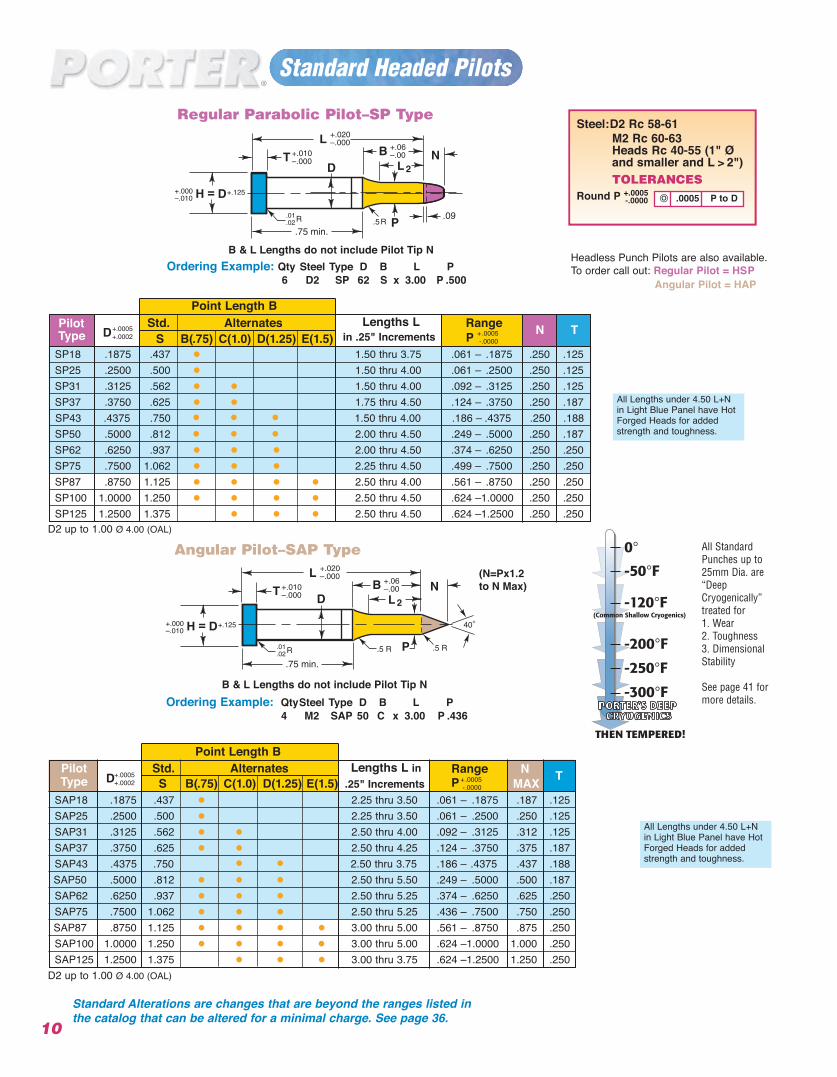
Standard Headed Pilots
10
Point Length B
Point Length B
H = D+.000–.010
+.125
2
B & L Lengths do not include Pilot Tip N
Regular Parabolic Pilot–SP Type
B & L Lengths do not include Pilot Tip N
Angular Pilot–SAP Type
H = D+.000–.010
+.125
2
Ordering Example: Qty Steel Type D B L P6 D2 SP 62 S x 3.00 P .500
Ordering Example: QtySteel Type D B L P4 M2 SAP 50 C x 3.00 P .436
Steel:D2 Rc 58-61M2 Rc 60-63Heads Rc 40-55 (1" Ø and smaller and L > 2")TOLERANCES
Round P +.0005-.0000
All Lengths under 4.50 L+Nin Light Blue Panel have HotForged Heads for addedstrength and toughness.
All Lengths under 4.50 L+Nin Light Blue Panel have HotForged Heads for addedstrength and toughness.
.0005 P to D
D2 up to 1.00 Ø 4.00 (OAL)
D2 up to 1.00 Ø 4.00 (OAL)
Pilot Std. Alternates Lengths L RangeType D S B(.75) C(1.0) D(1.25) E(1.5) in .25" Increments P N T
SP18 .1875 .437 • 1.50 thru 3.75 .061 – .1875 .250 .125SP25 .2500 .500 • 1.50 thru 4.00 .061 – .2500 .250 .125SP31 .3125 .562 • • 1.50 thru 4.00 .092 – .3125 .250 .125SP37 .3750 .625 • • 1.75 thru 4.50 .124 – .3750 .250 .187SP43 .4375 .750 • • •
• • •1.50 thru 4.00 .186 – .4375 .250 .188
SP50 .5000 .812 2.00 thru 4.50 .249 – .5000 .250 .187SP62 .6250 .937 • • • 2.00 thru 4.50 .374 – .6250 .250 .250SP75 .7500 1.062 • • • 2.25 thru 4.50 .499 – .7500 .250 .250SP87 .8750 1.125 • • • • 2.50 thru 4.00 .561 – .8750 .250 .250SP100 1.0000 1.250 • • • • 2.50 thru 4.50 .624 –1.0000 .250 .250SP125 1.2500 1.375 • • • 2.50 thru 4.50 .624 –1.2500 .250 .250
+.0005 +.0002 +.0005
-.0000
Pilot Std. Alternates Lengths L in Range NType D S B(.75) C(1.0) D(1.25) E(1.5) .25" Increments P MAX T
SAP18 .1875 .437 • 2.25 thru 3.50 .061 – .1875 .187 .125SAP25 .2500 .500 • 2.25 thru 3.50 .061 – .2500 .250 .125SAP31 .3125 .562 • • 2.50 thru 4.00 .092 – .3125 .312 .125SAP37 .3750 .625 • • 2.50 thru 4.25 .124 – .3750 .375 .187SAP43 .4375 .750 • • 2.50 thru 3.75 .186 – .4375 .437 .188SAP50 .5000 .812 • • • 2.50 thru 5.50 .249 – .5000 .500 .187SAP62 .6250 .937 • • • 2.50 thru 5.25 .374 – .6250 .625 .250SAP75 .7500 1.062 • • • 2.50 thru 5.25 .436 – .7500 .750 .250SAP87 .8750 1.125 • • • • 3.00 thru 5.00 .561 – .8750 .875 .250SAP100 1.0000 1.250 • • • • 3.00 thru 5.00 .624 –1.0000 1.000 .250SAP125 1.2500 1.375 • • • 3.00 thru 3.75 .624 –1.2500 1.250 .250
+.0005 +.0002 +.0005
-.0000
Headless Punch Pilots are also available.To order call out: Regular Pilot = HSP
Angular Pilot = HAP
Standard Alterations are changes that are beyond the ranges listed inthe catalog that can be altered for a minimal charge. See page 36.
All StandardPunches up to25mm Dia. are“DeepCryogenically” treated for 1. Wear2. Toughness3. DimensionalStability
See page 41 formore details.
(N=Px1.2to N Max)
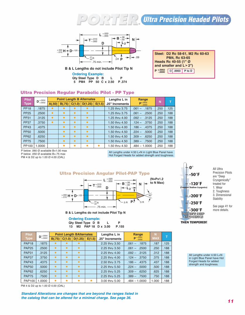
Steel: D2 Rc 58-61, M2 Rc 60-63PM4, Rc 63-65
Heads Rc 40-55 (1" Ø and smaller and L > 2")P +.0002
-.0000
Ultra Precision Headed Pilots
H = D+.000–.010
+.125
2
H = D+.000–.010
+.125
2
Ultra Precision Regular Parabolic Pilot - PP Type
B & L Lengths do not include Pilot Tip N
B & L Lengths do not include Pilot Tip N
Ultra Precision Angular Pilot-PAP Type
Ordering Example:Qty Steel Type D B L P13 M2 PAP 18 D x 3.00 P.155
Ordering Example:Qty Steel Type D B L P5 PM4 PP 50 C x 2.50 P .374
All UltraPrecision Pilotsare “DeepCryogenically”treated for1. Wear2. Toughness3. DimensionalStability
See page 41 formore details.
.0003 P to D
P below .060 Ø available B=1.00 max P below .050 Ø available B=.75 max PM 4 & D2 up to 1.00 Ø 4.00 (OAL)
All Lengths under 4.50 L+N in Light Blue Panel haveHot Forged Heads for added strength and toughness.
All Lengths under 4.50 L+Nin Light Blue Panel have HotForged Heads for addedstrength and toughness.
Pilot Point Length BAlternates Lengths L in Range NType D B(.75) C(1.0) D(1.25) E(1.5) .25" Increments P MAX T
PAP18 .1875 • • • 2.25 thru 3.50 .061 – .1875 .187 .125PAP25 .2500 • • • 2.25 thru 3.50 .061 – .2500 .250 .188PAP31 .3125 • • • 2.25 thru 4.00 .092 – .3125 .312 .188PAP37 .3750 • • • 2.25 thru 4.00 .124 – .3750 .375 .188PAP43 .4375 • • • 2.50 thru 3.75 .186 – .4375 .437 .188PAP50 .5000 • • • 2.25 thru 5.50 .224 – .5000 .500 .188PAP62 .6250 • • • 2.25 thru 5.25 .309 – .6250 .625 .188PAP75 .7500 • • • 2.25 thru 5.25 .389 – .7500 .750 .188PAP100 1.0000 • • • • 3.00 thru 5.00 .484 – 1.0000 1.000 .188
+.0002-.0000
+.0004 +.0002
Pilot Point Length B Alternates Lengths L in RangeType D
A(.50) B(.75) C(1.0) D(1.25) E(1.5) .25" Increments P N T
PP18 .1875 • • • • 1.25 thru 3.75 .061 – .1875 .250 .125PP25 .2500 • • • • 1.25 thru 3.75 .061 – .2500 .250 .188PP31 .3125 • • • • 1.25 thru 4.00 .092 – .3125 .250 .188PP37 .3750 • • • • 1.50 thru 4.50 .124 – .3750 .250 .188PP43 .4375 • • • 1.50 thru 4.00 .186 – .4375 .250 .188PP50 .5000 • • • 1.50 thru 4.50 .224 – .5000 .250 .188PP62 .6250 • • • 1.50 thru 4.50 .309 – .6250 .250 .188PP75 .7500 • • • 1.50 thru 4.50 .389 – .7500 .250 .188PP100 1.0000 • • • • 1.50 thru 4.50 .484 – 1.0000 .250 .188
+.0002-.0000
+.0004 +.0002
11
PM 4 & D2 up to 1.00 Ø 4.00 (OAL)
Standard Alterations are changes that are beyond the ranges listed inthe catalog that can be altered for a minimal charge. See page 36.
(N=Px1.2to N Max)
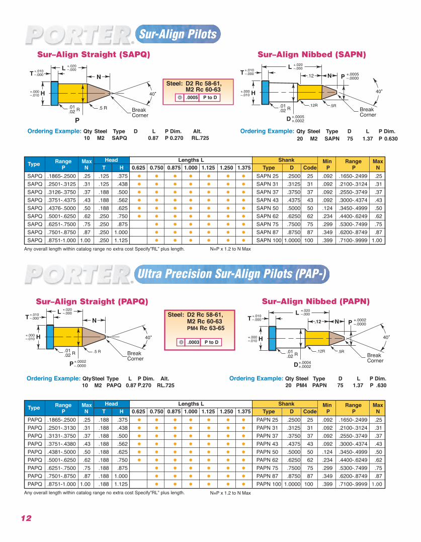
Sur–Align Straight (SAPQ)
Ordering Example: Ordering Example: Qty Steel Type D L P Dim. Qty Steel Type D L P Dim.Alt. 10 M2 SAPQ 0.87 P 0.270 RL.725 20 M2 SAPN 75 1.37 P 0.630
40•
BreakCorner
Steel: D2 Rc 58-61,M2 Rc 60-63.0005 P to D
Any overall length within catalog range no extra cost Specify”RL” plu N=P x 1.2 to N Max
N=P x 1.2 to N Max
s length.
Sur–Align Nibbed (SAPN)
40•
.12
.12R .5R
+.0005–.0000P
BreakCorner+.0005
+.0002
Range Max Head Lengths L Shank Min Range MaxType P N T H 0.625 0.750 0.875 1.000 1.125 1.250 1.375 Type D Code P P NSAPQ .1865-.2500 .25 .125 .375 • • • • • • • SAPN 25 .2500 25 .092 .1650-.2499 .25SAPQ .2501-.3125 .31 .125 .438 • • • • • • • SAPN 31 .3125 31 .092 .2100-.3124 .31SAPQ .3126-.3750 .37 .188 .500 • • • • • • • SAPN 37 .3750 37 .092 .2550-.3749 .37SAPQ .3751-.4375 .43 .188 .562 • • • • • • • SAPN 43 .4375 43 .092 .3000-.4374 .43SAPQ .4376-.5000 .50 .188 .625 • • • • • • • SAPN 50 .5000 50 .124 .3450-.4999 .50SAPQ .5001-.6250 .62 .250 .750 • • • • • • • SAPN 62 .6250 62 .234 .4400-.6249 .62SAPQ .6251-.7500 .75 .250 .875 • • • • • • SAPN 75 .7500 75 .299 .5300-.7499 .75SAPQ .7501-.8750 .87 .250 1.000 • • • • • • SAPN 87 .8750 87 .349 .6200-.8749 .87SAPQ .8751-1.000 1.00 .250 1.125 • • • • • • SAPN 100 1.0000 100 .399 .7100-.9999 1.00
Sur-Align Pilots
12
Sur–Align Straight (PAPQ)
Ordering Example: QtySteel Type L PP
Dim. Alt.10 M2 PAPQ 0.87 .270 RL.725
40•
BreakCorner +.0002
.0000
Steel: D2 Rc 58-61,M2 Rc 60-63PM4 Rc 63-65
.0003 P to D
Ultra Precision Sur-Align Pilots (PAP-)
Sur–Align Nibbed (PAPN)
40•
.12
.12R .5R
+.0002–.0000P
BreakCorner+.0004
+.0002
Ordering Example: Qty Steel Type D L P Dim.20 PM4 PAPN 75 1.37 P .630
Any overall length within catalog range no extra cost Specify”RL” plus length.
Range Max Head Lengths L Shank Min Range MaxType P N T H 0.625 0.750 0.875 1.000 1.125 1.250 1.375 Type D Code P P NPAPQ .1865-.2500 .25 .188 .375 • • • • • • • PAPN 25 .2500 25 .092 .1650-.2499 .25PAPQ .2501-.3130 .31 .188 .438 • • • • • • • PAPN 31 .3125 31 .092 .2100-.3124 .31PAPQ .3131-.3750 .37 .188 .500 • • • • • • • PAPN 37 .3750 37 .092 .2550-.3749 .37PAPQ .3751-.4380 .43 .188 .562 • • • • • • • PAPN 43 .4375 43 .092 .3000-.4374 .43PAPQ .4381-.5000 .50 .188 .625 • • • • • • • PAPN 50 .5000 50 .124 .3450-.4999 .50PAPQ .5001-.6250 .62 .188 .750 • • • • • • • PAPN 62 .6250 62 .234 .4400-.6249 .62PAPQ .6251-.7500 .75 .188 .875 • • • • • • PAPN 75 .7500 75 .299 .5300-.7499 .75PAPQ .7501-.8750 .87 .188 1.000 • • • • • • PAPN 87 .8750 87 .349 .6200-.8749 .87PAPQ .8751-1.000 1.00 .188 1.125 • • • • • • PAPN 100 1.0000 100 .399 .7100-.9999 1.00
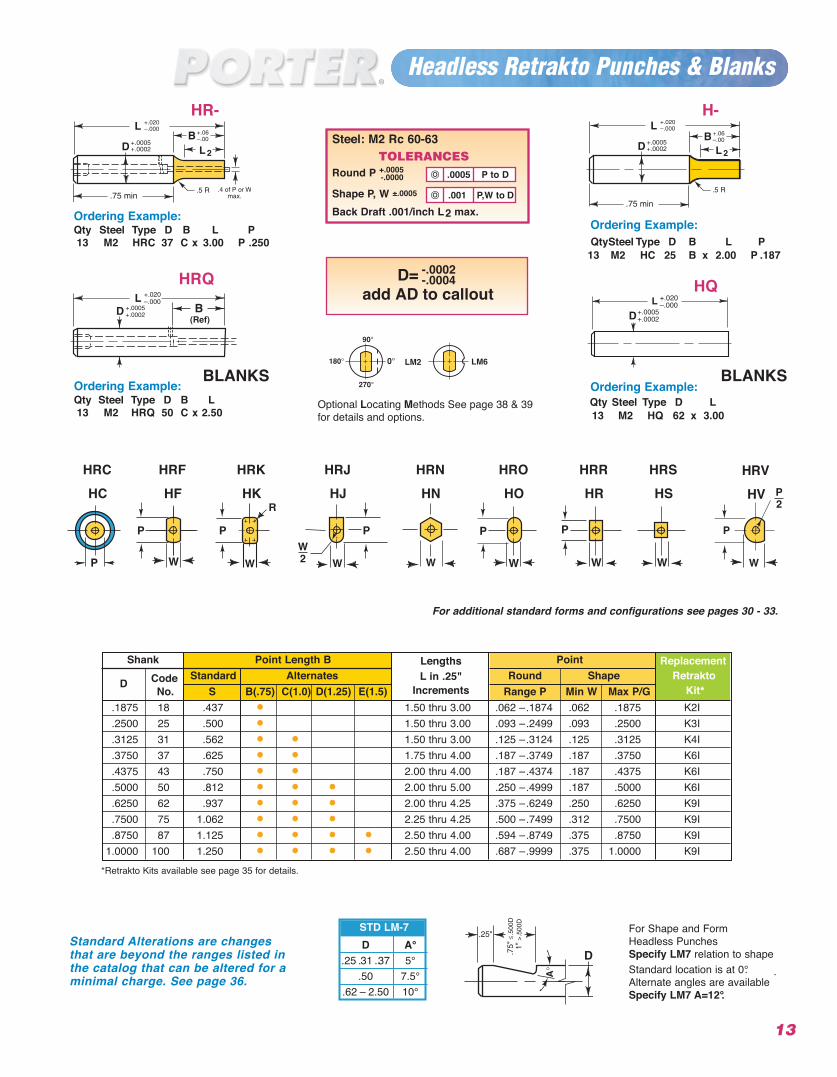
Headless Retrakto Punches & Blanks
2
Ordering Example:QtySteel Type D B L P
13 M2 HC 25 B x 2.00 P .187
+.020–.000
2
*Retrakto Kits available see page 35 for details.
For Shape and Form Headless Punches Specify LM7 relation to shape
.Standard location is at 0°.Alternate angles are available Specify LM7 A=12°.
D A°.25 .31 ..37 5°
.50 7.5°.62 – 2.50 10°
STD LM-7
Ordering Example:Qty Steel Type D B L P13 M2 HRC 37 C x 3.00 P .250
Ordering Example:Qty Steel Type D B L13 M2 HRQ 50 C x 2.50
Standard Alterations are changesthat are beyond the ranges listed inthe catalog that can be altered for aminimal charge. See page 36.
HQHRQ
Shank Point Length B Lengths Point ReplacementCode Standard Alternates L in .25" Round Shape Retrakto
DNo. S B(.75) C(1.0) D(1.25) E(1.5) Increments Range P Min W Max P/G Kit*
.1875 18 .437 • 1.50 thru 3.00 .062 –.1874 .062 .1875 K2I
.2500 25 .500 • 1.50 thru 3.00 .093 –.2499 .093 .2500 K3I
.3125 31 .562 • • 1.50 thru 3.00 .125 –.3124 .125 .3125 K4I
.3750 37 .625 • • 1.75 thru 4.00 .187 –.3749 .187 .3750 K6I
.4375 43 .750 • • 2.00 thru 4.00 .187 –.4374 .187 .4375 K6I
.5000 50 .812 • • • 2.00 thru 5.00 .250 –.4999 .187 .5000 K6I
.6250 62 .937 • • • 2.00 thru 4.25 .375 –.6249 .250 .6250 K9I
.7500 75 1.062 • • • 2.25 thru 4.25 .500 –.7499 .312 .7500 K9I
.8750 87 1.125 • • • • 2.50 thru 4.00 .594 –.8749 .375 .8750 K9I1.0000 100 1.250 • • • • 2.50 thru 4.00 .687 –.9999 .375 1.0000 K9I
Steel: M2 Rc 60-63TOLERANCES
Round P +.0005-.0000
Shape P, W ±.0005
Back Draft .001/inch L2 max..001 P,W to D
.0005 P to D
13
HR- H-
Ordering Example: Qty Steel Type D L13 M2 HQ 62 x 3.00
BLANKSBLANKS
D= add AD to callout
-.0002-.0004
LM2 LM6
Optional Locating Methods See page 38 & 39for details and options.
For additional standard forms and configurations see pages 30 - 33.
HKHF HJ HN HO HR HS HVHCHRKHRF HRJ HRN HRO HRR HRS HRVHRC
14
+.062–.000
+.015–.000
Ordering Example:Qty Steel Type D L P W Locate
6 M2 NDO 100 x 1.25 P.605 W.305 LM1
LB
H = D ØR
.01
.02 R
+.020–.000
+.000–.010
+.0005+.0002
+.0005+.0002
+.010–.000
+.125
.188
D
+.062–.000
* Alternate “B” lengths available see page 15 (Taper Relief Dies). N = ND only.
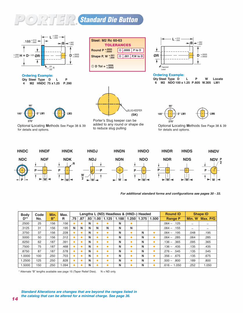
Ordering Example: Qty Steel Type D L P4 M2 HNDC 75 x1.25 P.390
Body Code Min. Max. Lengths L (ND) Headless & (HND–) Headed Round ID Shape IDD** No. B* R .75 .87 .93 1.00 1.125 1.188 1.250 1.375 1.500 Range P Min. W Max. P/G
.2500 .156 .156 • • N • • N • .064 – .125 – –
.3125 .156 .195 N N N N N N N .064 – .155 – –
.3750 .156 .228 • • N • • N • N • .064 – .195 .048 .195
.5000 .156 .312 • • N • • N • N • .064 – .285 .064 .285
.6250 .187 .391 • • N • • N • N • .136 – .365 .095 .365
.7500 .187 .468 • • N • • N • N • .136 – .435 .135 .435
.8750 .187 .578 • • N • • N • N • .276 – .545 .135 .5451.0000 .250 .703 • • N • • N • N • .356 – .675 .135 .6751.2500 .250 .828 • • N • • N • N • .500 – .800 .189 .8001.5000
25313750627587
100125150 .250 1.094 • • N • • N • N • .616 – 1.050 .252 1.050
.001 P,W to D
.0005 P to D
Steel: M2 Rc 60-63TOLERANCES
Round P +.0005-.0000
Shape P, W +.001-.000
D Tol = +.0006 +.0002
andard Die ButtonSt
TaperedLead
Optional Locating Methods See Page 38 & 39 for details and options.
Optional Locating Methods See Page 38 & 39 for details and options.
Porter’s S
SLUG-KEEPER
lug keeper can beadded to any round or shape dieto reduce slug pulling
(SK)
For additional standard forms and configurations see pages 30 - 33.
NDKNDF NDJ NDN NDO NDR NDS NDVNDC
HNDKHNDF HNDJ HNDN HNDO HNDR HNDS HNDVHNDC
Standard Alterations are changes that are beyond the ranges listed inthe catalog that can be altered for a minimal charge. See page 36.
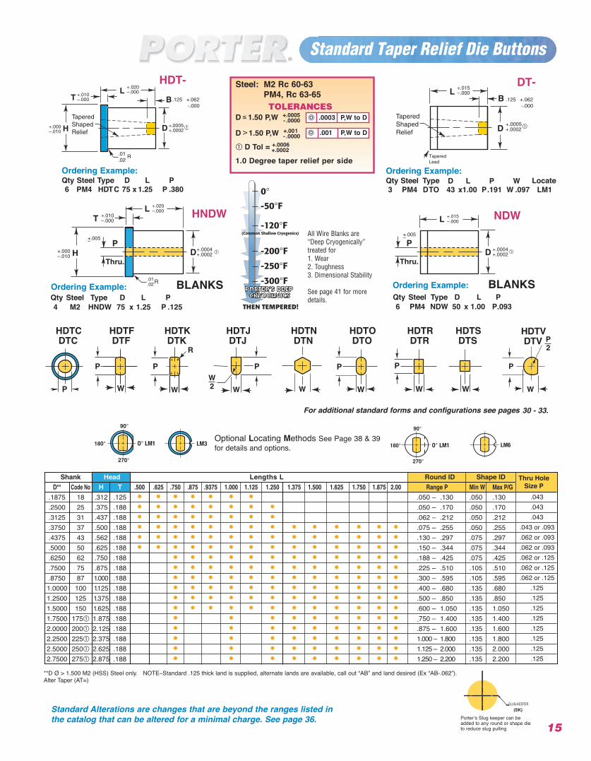
Standard Taper Relief Die Buttons
Steel: M2 Rc 60-63PM4, Rc 63-65TOLERANCES
D ≤ 1.50 P,W +.0005- .0000
D > 1.50 P,W +.001- .0000
D Tol = +.0006+.0002
1.0 Degree taper relief per side
.001 P,W to D
.0003 P,W to D
**D Ø > 1.500 M2 (HSS) Steel only. NOTE–Standard .125 thick land is supplied, alternate lands are available, call out “AB” and land desired (Ex “AB-.062”).Alter Taper (AT=)
Ordering Example:Qty Steel Type Locate3 PM4 DTO 43 x1.00 P.191 W .097 LM1
Ordering Example:Qty Steel Type D L P6 PM4 HDTC 75 x 1.25 P .380
B
.0005
B
.0005
+.062 -.000
.125+.062 -.000
.125
15
Shank Head Lengths L Round ID Shape IDD** Code No H T .500 .625 .750 .875 .9375 1.000 1.125 1.250 1.375 1.500 1.625 1.750 1.875 2.00 Range P Min W Max P/G
.1875 18 .312 .125 • • • • • • • .050 – .130 .050 .130
.2500 25 .375 .188 • • • • • • • • .050 – .170 .050 .170
.3125 31 .437 .188 • • • • • • • • .062 – .212 .050 .212
.3750 37 .500 .188 • • • • • • • • • • • • • • .075 – .255 .050 .255
.4375 43 .562 .188 • • • • • • • • • • • • • • .130 – .297 .075 .297
.5000 50 .625 .188 • • • • • • • • • • • • • • .150 – .344 .075 .344
.6250 62 .750 .188 • • • • • • • • • • • • .188 – .425 .075 .425
.7500 75 .875 .188 • • • • • • • • • • • • .225 – .510 .105 .510
.8750 87 1.000 .188 • • • • • • • • • • • • .300 – .595 .105 .5951.0000 100 1.125 .188 • • • • • • • • • • • • .400 – .680 .135 .6801.2500 125 1.375 .188 • • • • • • • • • • • • .500 – .850 .135 .8501.5000 150 1.625 .188 • • • • • • • • • • • • .600 – 1.050 .135 1.0501.7500 175 1.875 .188 • • • • • • • • • .750 – 1.400 .135 1.4002.0000 200 2.125 .188 • • • • • • • • • .875 – 1.600 .135 1.6002.2500 225 2.375 .188 • • • • • • • • • 1.000 – 1.800 .135 1.8002.5000 250 2.625 .188 • • • • • • • • • 1.125 – 2.000 .135 2.0002.7500 275 2.875 .188 • • • • • • • • • 1.250 – 2.200 .135 2.200
HDT- DT-
D L P W
TaperedLead
Standard Alterations are changes that are beyond the ranges listed inthe catalog that can be altered for a minimal charge. See page 36. Porter’s S
SLUG-KEEPER
lug keeper can beadded to any round or shape dieto reduce slug pulling
(SK)
.043
.043
.043.043 or .093.062 or .093.062 or .093.062 or .125.062 or .125.062 or .125
.125
.125
.125
.125
.125
.125
.125
.125
Thru HoleSize P
H +.000–.010
+.005–+.005–
T HNDW
Ordering Example:Qty Steel Type D L P4 M2 HNDW 75 x 1.25 P .125
Ordering Example:Qty Steel Type D L P6 PM4 NDW 50 x 1.00 P.093
NDW
All Wire Blanks are“Deep Cryogenically”treated for1. Wear2. Toughness3. Dimensional Stability
See page 41 for moredetails.
Optional Locating Methods See Page 38 & 39for details and options.
For additional standard forms and configurations see pages 30 - 33.
DTKDTF DTJ DTN DTO DTR DTS DTVDTCHDTKHDTF HDTJ HDTN HDTO HDTR HDTS HDTVHDTC
BLANKSBLANKS
16
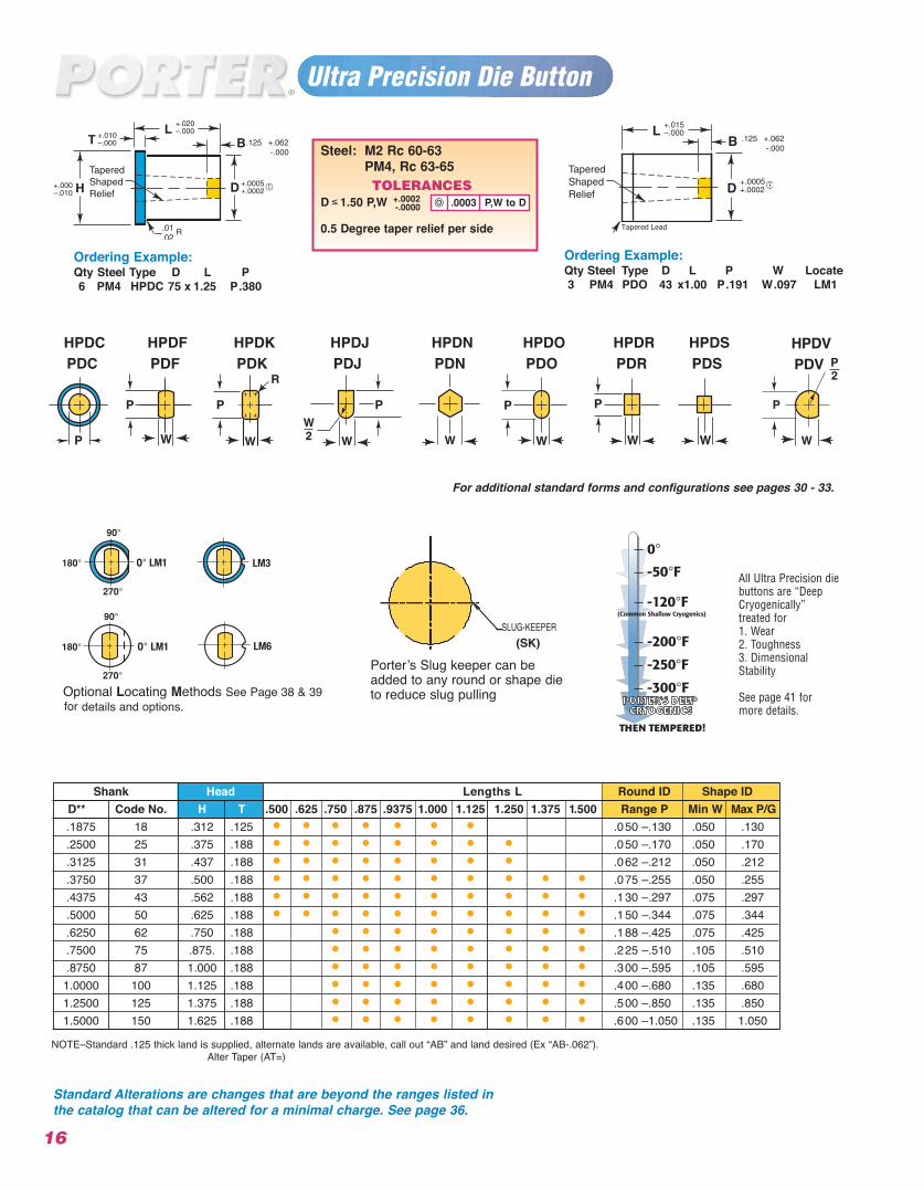
Ultra Precision Die Button
Optional Locating Methods See Page 38 & 39 for details and options.
Porter’s S
SLUG-KEEPER
lug keeper can beadded to any round or shape dieto reduce slug pulling
(SK)
For additional standard forms and configurations see pages 30 - 33.
PDKPDF PDJ PDN PDO PDR PDS PDVPDCHPDKHPDF HPDJ HPDN HPDO HPDR HPDS HPDVHPDC
B
.0005
Ordering Example:Qty Steel Type D L P W Locate3 PM4 PDO 43 x1.00 P.191 W.097 LM1
B
.0005
+.062 -.000
.125+.062 -.000
.125
Tapered Lead
Standard Alterations are changes that are beyond the ranges listed inthe catalog that can be altered for a minimal charge. See page 36.
All Ultra Precision diebuttons are “DeepCryogenically” treated for 1. Wear2. Toughness3. DimensionalStability
See page 41 for more details.
NOTE–Standard .125 thick land is supplied, alternate lands are available, call out “AB” and land desired (Ex “AB-.062”).Alter Taper (AT=)
Shank Head Lengths L Round ID Shape IDD** Code No. H T .500 .625 .750 .875 .9375 1.000 1.125 1.250 1.375 1.500 Range P Min W Max P/G
18 .312 .125 • • • • • • • .050 –.130 .05025 .375 .188 • • • • • • • • .050 –.170 .05031 .437 .188 • • • • • • • • .062 –.212 .050 37 .500 .188 • • • • • • • • • • .075 –.255 .050 43 .562 .188 • • • • • • • • • • .130 –.297 .07550 .625 .188 • • • • • • • • • • .150 –.344 .07562 .750 .188 • • • • • • • • .188 –.425 .07575 .875. .188 • • • • • • • • .225 –.510 .10587 1.000 .188 • • • • • • • • .300 –.595 .105100 1.125 .188 • • • • • • • • .400 –.680 .135125 1.375 .188 • • • • • • • • .500 –.850 .135150 1.625 .188 • • • • • • • • .600 –1.050 .135
.1875
.2500
.3125
.3750
.4375
.5000
.6250
.7500
.87501.00001.25001.5000
.130
.170
.212
.255
.297
.344
.425
.510
.595
.680
.8501.050
Ordering Example:Qty Steel Type D L P6 PM4 HPDC 75 x 1.25 P.380
Steel: M2 Rc 60-63PM4, Rc 63-65TOLERANCES
D ≤ 1.50 P,W +.0002-.0000
0.5 Degree taper relief per side
.0003 P,W to D
17Locating flats and dowels, see page 38 & 39.
• Guide Bushing I.D. should be at least .0005 larger than the punch point that it is used with.
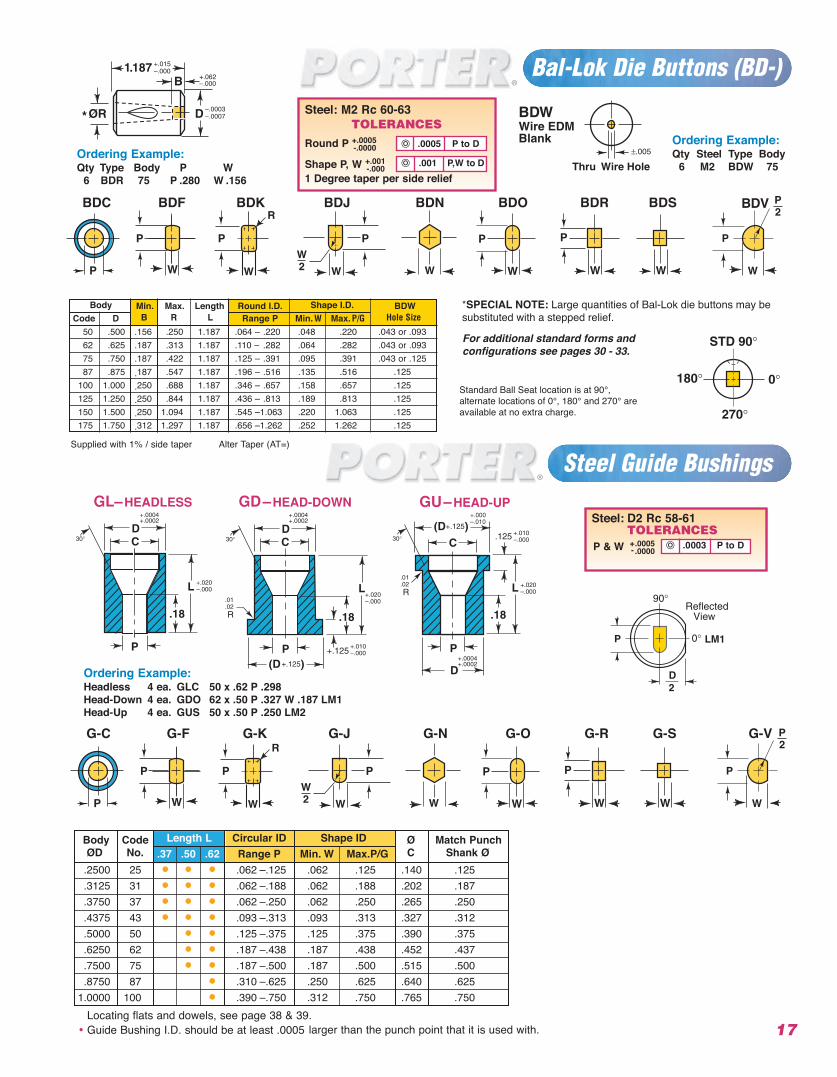
Ordering Example:Headless 4 ea. GLC 50 x .62 P .298Head-Down 4 ea. GDO 62 x .50 P .327 W .187 LM1Head-Up 4 ea. GUS 50 x .50 P .250 LM2
. 00 03 P to D
Steel: D2 Rc 58-61TOLERANCES
P & W +-
Bal-Lok Die Buttons (BD-)
BDKBDF BDJ BDN BDO BDR BDS BDVBDC
Supplied with 1% / side taper Alter Taper (AT=)
Standard Ball Seat location is at 90°, alternate locations of 0°, 180° and 270° are available at no extra charge.
Steel Guide Bushings
*SPECIAL NOTE: Large quantities of Bal-Lok die buttons may be substituted with a stepped relief.
For additional standard forms and configurations see pages 30 - 33.
G-C G-F G-K G-J G-N G-O G-R G-S G-V
*
+.062–.000
Ordering Example:Qty Type Body P W
6 BDR 75 P .280 W .156
Ordering Example:Qty Steel Type Body
6 M2 BDW 75
Body Min. Max. Length Round I.D. Shape I.D. BDWCode D B R L Range P Min. W Max. P/G Hole Size
50 .500 .156 .250 1.187 .064 – .220 .048 .220 .043 or .09362 .625 .187 .313 1.187 .110 – .282 .064 .282 .043 or .09375 .750 .187 .422 1.187 .125 – .391 .095 .391 .043 or .12587 .875 .187 .547 1.187 .196 – .516 .135 .516
100 1.000 .250 .688 1.187 .346 – .657 .158 .657 .125.125
125 1.250 .250 .844 1.187 .436 – .813 .189 .813 .125150 1.500 .250 1.094 1.187 .545 –1.063 .220 1.063 .125175 1.750 .312 1.297 1.187 .656 –1.262 .252 1.262 .125
Steel: M2 Rc 60-63TOLERANCES
Round P +.0005-.0000
Shape P, W +.001-.000
1 Degree taper per side relief.001 P,W to D
.0005 P to D
Body Code Length L Circular ID Shape ID Ø Match PunchØD No. .37 .50 .62 Range P Min. W Max.P/G C Shank Ø.2500 25 • • • .062 –.125 .062 .125 .140 .125.3125 31 • • • .062 –.188 .062 .188 .202 .187.3750 37 • • • .062 –.250 .062 .250 .265 .250.4375 43 • • • .093 –.313 .093 .313 .327 .312.5000 50 • • .125 –.375 .125 .375 .390 .375.6250 62 • • .187 –.438 .187 .438 .452 .437.7500 75 • • .187 –.500 .187 .500 .515 .500.8750 87 • .310 –.625 .250 .625 .640 .625
1.0000 100 • .390 –.750 .312 .750 .765 .750
GL–HEADLESS GD–HEAD-DOWN+.000–.010
GU–HEAD-UP
.0005
.0000
PD B
.7D1.8D
L
+.0005–.0000+.0003
–.0000
+.020–.000
60
D
LH
T
P+.0005–.0000
+.020–.000
+.0003–.0000
+.010–.000
+.000–.002
60
B
L +.020–.000
D +.0003–.0000
1.8 DREF.
.7D
60°
.09
.25
NPP A HEA(PILOT)
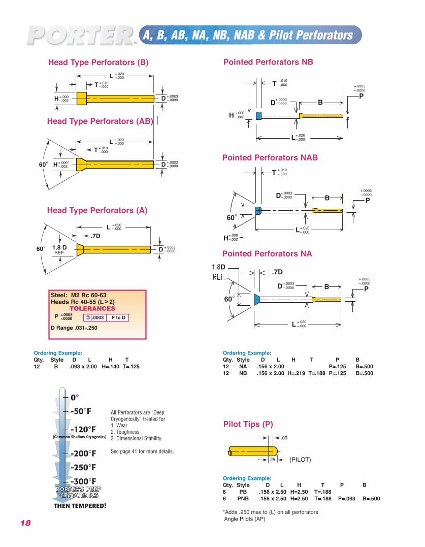
Steel: M2 Rc 60-63Heads Rc 40-55 (L > 2)
TOLERANCESP +.0005
-.0000
D Range .031-.250
A, B, AB, NA, NB, NAB & Pilot Perforators
Ordering Example:Qty. Style D L H T P B12 NA .156 x 2.00 P=.125 B=.50012 NB .156 x 2.00 H=.219 T=.188 P=.125 B=.500
Ordering Example:Qty. Style D L H T P B6 PB .156 x 2.50 H=2.50 T=.1886 PNB .156 x 2.50 H=2.50 T=.188 P=.093 B=.500
*Adds .250 max to (L) on all perforatorsAngle Pilots (AP)
Ordering Example:Qty. Style D L H T12 B .093 x 2.00 H=.140 T=.125
.0003 P to D
Head Type Perforators (A)
Pointed Perforators NBHead Type Perforators (B)
Pointed Perforators NAB
Head Type Perforators (AB)
Pointed Perforators NA
Pilot Tips (P)
18
(PILOT)
.09
.25*
D +.0003–.0000
TL +.020
–.000+.010–.000
+.000–.002H
D +.0003–.0000
L +.020–.000
+.000*–.002
T +.010–.000
H60°
.09
NPP AB H
All Perforators are “DeepCryogenically” treated for1. Wear2. Toughness3. Dimensional Stability
See page 41 for more details.
+.0005–.0000
PB
H
L+.020–.000
+.000–.002
D
T
+.0003–.0000
+.010–.000
Catalog CD Length h tNo. m6 L
BHQ–37 37
BHQ–50 50
BHQ–62 62
BHQ–75 75
BHQ–100 100
BHQ–125 125
19
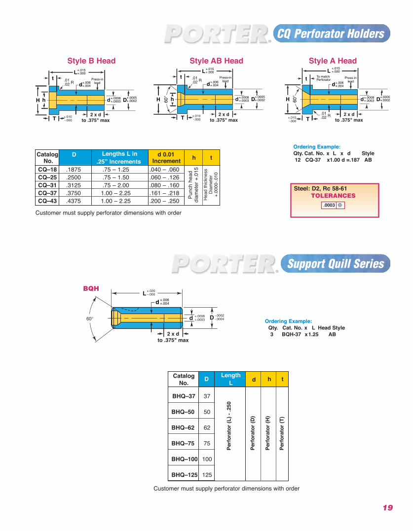
Support Quill Series
Ordering Example:Qty. Cat. No. x L x d Style12 CQ-37 x1.00 d =.187 AB
Catalog D Lengths L in d 0.01 h tNo. .25” Increments IncrementCQ–18 .1875 .75 – 1.25 .040 – .060CQ–25 .2500 .75 – 1.50 .060 – .126CQ–31 .3125 .75 – 2.00 .080 – .160CQ–37 .3750 1.00 – 2.25 .161 – .218CQ–43 .4375 1.00 – 2.25 .200 – .250 Pu
nch
head
diam
eter
+.0
15
Ordering Example:Qty. Cat. No. x L Head Style3 BQH-37 x1.25 AB
Style B Head Style AB Head Style A Head
Hea
d th
ickn
ess
Dia
met
er
+.00
00-.0
10
Perf
orat
or (L
) - .2
50
Perf
orat
or (D
)
Perf
orat
or (H
)
Perf
orat
or (T
)
dD LengthL
Customer must supply perforator dimensions with order
Customer must supply perforator dimensions with order
Steel: D2, Rc 58-61TOLERANCES
.0003
H
t
T
D
L
h
d
+.0005+.0002
+.015+.000
+.006+.004
Press-inlead
2 x dto .375" max
+.010 -.000
+.0008+.0003 60
°
T
L+.015+.000
t
H h
d
Press-inlead+.006
+.004
2 x dto .375" max
D+.0005+.0002
+.010 -.000
+
+.0008+.0003
+
60°
T
+.015+.000
t
H
To matchPerforator
L
+.006+.004d
Press-inlead
2 x dto .375" max
D+.0005+.0002
+.010 -.000
+
+.0008+.0003
2 x dto .375" max
d +.006+.004
BQH
CQ Perforator Holders
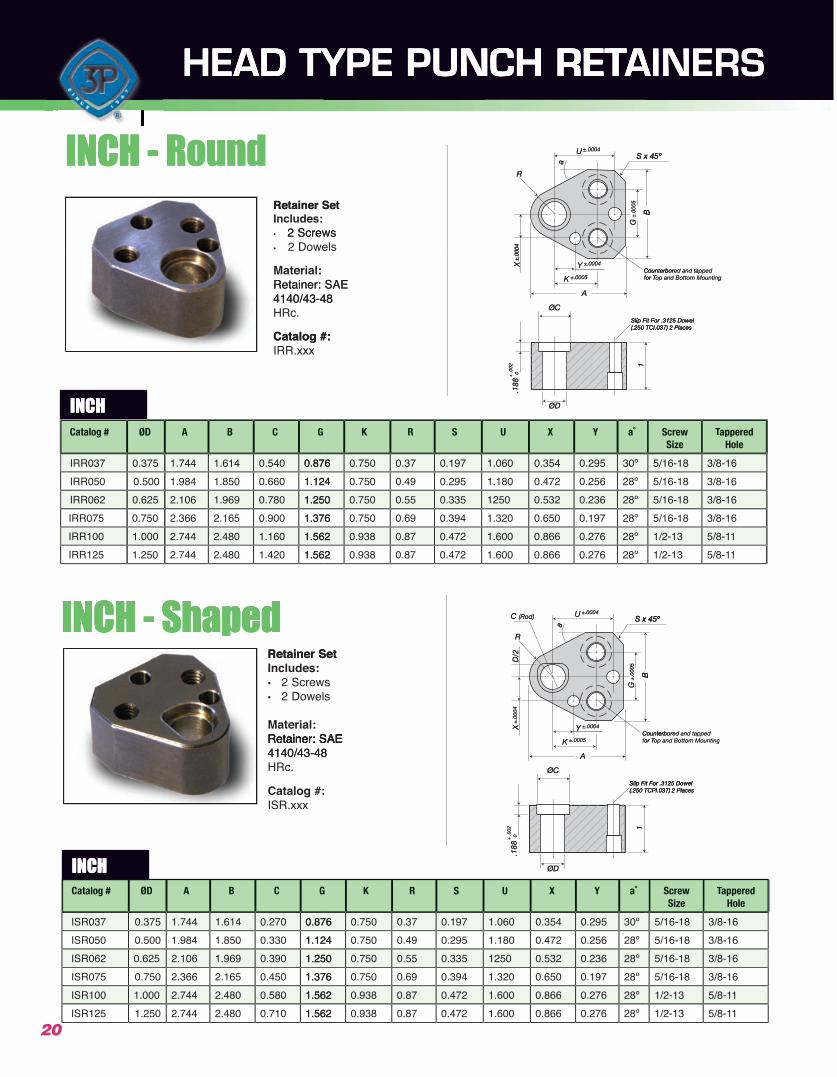
HEAD TYPE PUNCH RETAINERS
Slip Fit For .3125 Dowel(.250 TCI.037) 2 Places
Counterbored and tappedfor Top and Bottom Mounting
ØD
ØC
U
a
±.0004
Y ±.0004
K ±.0005
±.0
005
±.0
004
A
X
R
S x 45º
B
G1
.188
+ .0
02 0
Slip Fit For .3125 Dowel(.250 TCPI.037) 2 Places
Counterbored and tappedfor Top and Bottom Mounting
ØD
ØC
UC (Rod)
a
±.0004
Y ±.0004
K ±.0005
±.0
005
±.0
004
A
XD
/2
R
S x 45º
B
G1
.188
+ .0
02 0
INCH - Round
INCH - Shaped
INCH
HEAD TYPE PUNCH RET
HEAD TYPE PUNCH RET
A NCH RET TAINERS
AINERS
CH - RIN
Retainer Set Includes:• 2 Screws• 2 Dowels
oundCH - R
Retainer Set
2 Screws
U
a
±.0004
±.0
005
±.0
004
R
S x 45º
B
G
S x 45º
B
INCH
Material:Retainer: SAE 4140/43-48 HRc.
Catalog #:IRR.xxx
Retainer: SAE 4140/43-48
Catalog #:
Slip Fit For .3125 Dowel(.250 TCI.037) 2 Places
Counterborfor T
ØD
ØC
Y ±.0004
K ±.0005
±.0
004
A
X
1
.188
+ .0
02 0
Slip Fit For .3125 Dowel(.250 TCI.037) 2 Places
ed and tappedCounterborop and Bottom Mountingfor T Top and Bottom Mounting
Catalog #
IRR037
ØD
0.375
IRR062IRR050 0.500
0.625
IRR100IRR075 0.750
1.000IRR125 1.250
A
1.744
B C G
1.614 0.540 0.876
2.1061.984 1.850 0.660 1.124
1.969 0.780 1.250
2.7442.366 2.165 0.900 1.376
2.480 1.160 1.5622.744 2.480 1.420 1.562
K
0.876
R S
0.750 0.37 0.197
1.2501.124 0.750 0.49 0.295
0.750 0.55 0.335
1.5621.376 0.750 0.69 0.394
0.938 0.87 0.4721.562 0.938 0.87 0.472
U
1.060
X Y
0.354 0.295 30º
12501.180 0.472 0.256 28º
0.532 0.236 28º
1.6001.320 0.650 0.197 28º
0.866 0.276 28º1.600 0.866 0.276 28º
Screw
5/16-18Size
appered TTappered Hole
INCHINCHCatalog # ØD A B C G K R S U X Y Screw
Sizeappered TTappered
Hole
3/8-16
5/16-185/16-18 3/8-16
3/8-16
1/2-135/16-18 3/8-16
15/8-11/2-13 15/8-1
CH - ShapedIN
Retainer Set Includes:• 2 Screws• 2 Dowels
Material:Retainer: SAE
CH - Shaped
Retainer Set
Retainer: SAE
Counterbor
UC (Rod)
a
±.0004
Y ±.0004
±.0
005
±.0
004
XD
/2
R
S x 45º
B
G
ed and tappedCounterbor
S x 45º
B
Retainer: SAE 4140/43-48 HRc.
Catalog #:ISR.xxx
Retainer: SAE 4140/43-48
Slip Fit For .3125 Dowel(.250 TCPI.037) 2 Places
for T
ØD
ØC
K ±.0005
A
1
.188
+ .0
02 0
Slip Fit For .3125 Dowel(.250 TCPI.037) 2 Places
op and Bottom Mountingor T Top and Bottom Mounting
ISR037 0.375
ISR062ISR050 0.500
0.625
ISR100ISR075 0.750
1.000ISR125 1.250
1.744 1.614 0.270 0.876
2.1061.984 1.850 0.330 1.124
1.969 0.390 1.250
2.7442.366 2.165 0.450 1.376
2.480 0.580 1.5622.744 2.480 0.710 1.562
0.876 0.750 0.37 0.197
1.2501.124 0.750 0.49 0.295
0.750 0.55 0.335
1.5621.376 0.750 0.69 0.394
0.938 0.87 0.4721.562 0.938 0.87 0.472
1.060 0.354 0.295 30º
12501.180 0.472 0.256 28º
0.532 0.236 28º
1.6001.320 0.650 0.197 28º
0.866 0.276 28º1.600 0.866 0.276 28º
5/16-18 3/8-16
5/16-185/16-18 3/8-16
3/8-16
1/2-135/16-18 3/8-16
15/8-11/2-13 15/8-1
20
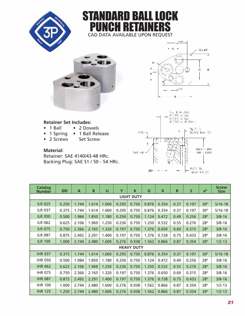
Retainer Set Includes:
Material:
CatalogNumber ØD A B U Y K G X R aº
ScrewSizeS
LIGHT DUTY
HEAVY DUTY
INCH
STANDARD BALL LOCK PUNCH RETAINERS
21
22
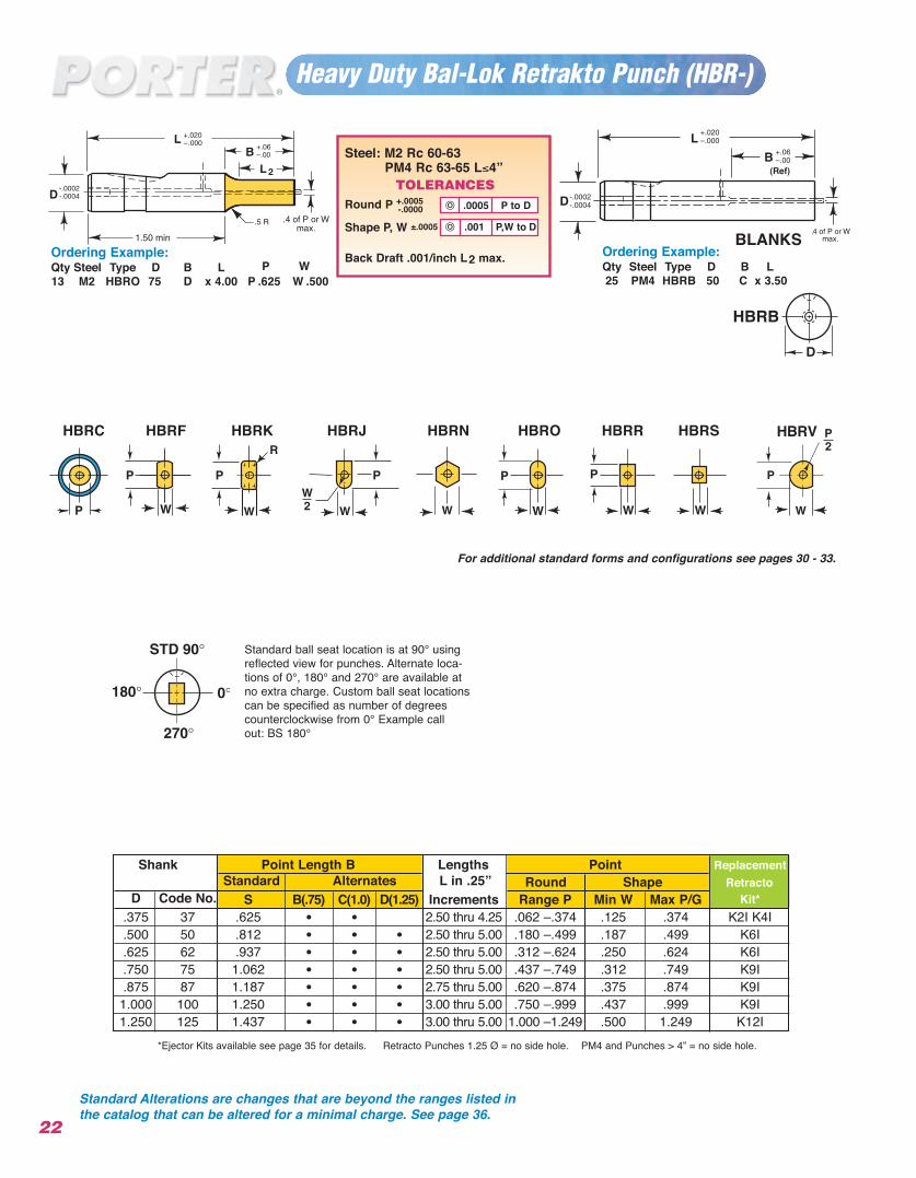
Heavy Duty Bal-Lok Retrakto Punch (HBR-)
Ordering Example: Qty Steel Type D B L13 M2 HBRO 75 D x 4.00 P .625 W .500
Ordering Example:Qty Steel Type D B L25 PM4 HBRB 50 C x 3.50
.001 P,W to D
.0005 P to D
2
*Ejector Kits available see page 35 for details. Retracto Punches 1.25 Ø = no side hole. PM4 and Punches > 4” = no side hole.
Steel: M2 Rc 60-63PM4 Rc 63-65 L≤4”
TOLERANCESRound P +.0005
-.0000
Shape P, W ±.0005
Back Draft .001/inch L2 max.
Shank Point Length B Lengths Point ReplacementStandard Alternates L in .25” Round Shape Retracto
D Code No. S B(.75) C(1.0) D(1.25) Increments Range P Min W Max P/G Kit*.375 37 .625 • • 2.50 thru 4.25 .062 –.374 .125 .374 K2I K4I.500 50 .812 • • • 2.50 thru 5.00 .180 –.499 .187 .499 K6I.625 62 .937 • • • 2.50 thru 5.00 .312 –.624 .250 .624 K6I.750 75 1.062 • • • 2.50 thru 5.00 .437 –.749 .312 .749 K9I.875 87 1.187 • • • 2.75 thru 5.00 .620 –.874 .375 .874 K9I
1.000 100 1.250 • • • 3.00 thru 5.00 .750 –.999 .437 .999 K9I1.250 125 1.437 • • • 3.00 thru 5.00 1.000 –1.249 .500 1.249 K12I
P W
BLANKS
Standard Alterations are changes that are beyond the ranges listed inthe catalog that can be altered for a minimal charge. See page 36.
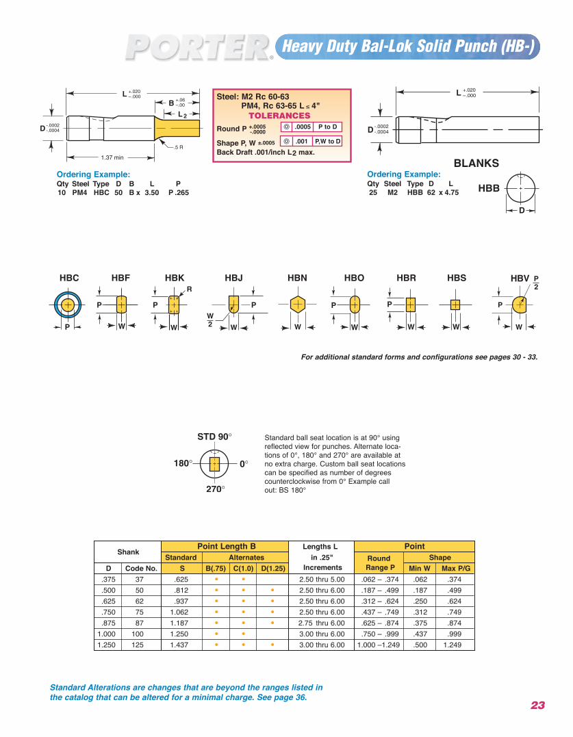
Standard ball seat location is at 90° usingreflected view for punches. Alternate loca-tions of 0°, 180° and 270° are available atno extra charge. Custom ball seat locationscan be specified as number of degreescounterclockwise from 0° Example call out: BS 180°
HBRKHBRF HBRJ HBRN HBRO HBRR HBRS HBRVHBRC
For additional standard forms and configurations see pages 30 - 33.
23
2
Ordering Example:Qty Steel Type D B L P10 PM4 HBC 50 B x 3.50 P .265
Ordering Example:Qty Steel Type D L25 M2 HBB 62 x 4.75
Standard ball seat location is at 90° usingreflected view for punches. Alternate loca-tions of 0°, 180° and 270° are available atno extra charge. Custom ball seat locationscan be specified as number of degreescounterclockwise from 0° Example call out: BS 180°
Steel: M2 Rc 60-63PM4, Rc 63-65 L ≤ 4"
TOLERANCESRound P +.0005
-.0000
Shape P, W ±.0005
Back Draft .001/inch L2 max..001 P,W to D
.0005 P to D
Heavy Duty Bal-Lok Solid Punch (HB-)
ShankPoint Length B Lengths L Point
Standard Alternates in .25" Round ShapeD Code No. S B(.75) C(1.0) D(1.25) Increments Range P Min W Max P/G
.375 37 .625 • • 2.50 thru 5.00 .062 – .374 .062 .374
.500 50 .812 • • • 2.50 thru 6.00 .187 – .499 .187 .499
.625 62 .937 • • • 2.50 thru 6.00 .312 – .624 .250 .624
.750 75 1.062 • • • 2.50 thru 6.00 .437 – .749 .312 .749
.875 87 1.187 • • • 2.75 thru 6.00 .625 – .874 .375 .8741.000 100 1.250 • • 3.00 thru 6.00 .750 – .999 .437 .9991.250 125 1.437 • • • 3.00 thru 6.00 1.000 –1.249 .500 1.249
HBKHBF HBJ HBN HBO HBR HBS HBVHBC
For additional standard forms and configurations see pages 30 - 33.
BLANKS
Standard Alterations are changes that are beyond the ranges listed inthe catalog that can be altered for a minimal charge. See page 36.
24
HBK–
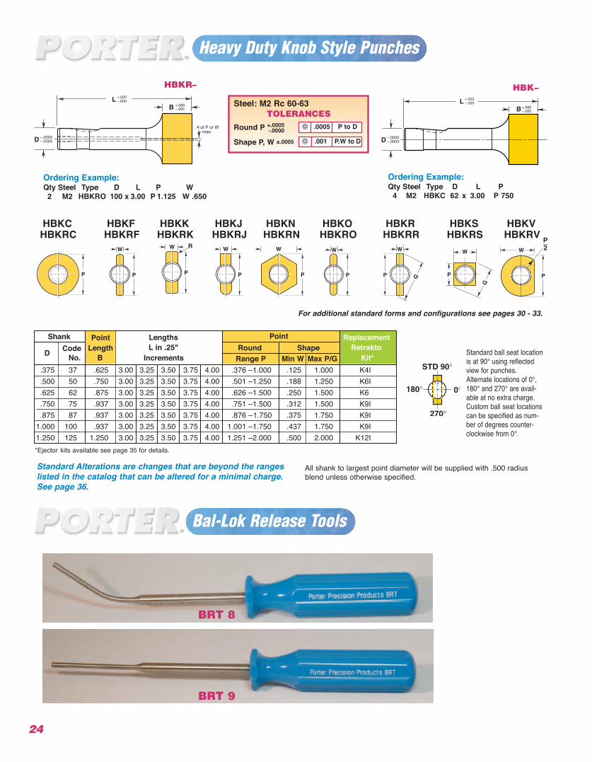
Ordering Example:Qty Steel Type D L P
4 M2 HBKC 62 x 3.00 P 750
Ordering Example:Qty Steel Type D L P W2 M2 HBKRO 100 x 3.00 P 1.125 W .650
Steel: M2 Rc 60-63TOLERANCES
Round P +.0005-.0000
Shape P, W ±.0005 .001 P,W to D
.0005 P to D
Bal-Lok Release Tools
HBKR–
*Ejector kits available see page 35 for details.
Heavy Duty Knob Style Punches
Shank Point Lengths Point ReplacementCode Length L in .25" Round Shape Retrakto
D No. B Increments Range P Min W Max P/G Kit*.375 37 .625 3.00 3.25 3.50 3.75 4.00 .376 –1.000 .125 1.000 K4I.500 50 .750 3.00 3.25 3.50 3.75 4.00 .501 –1.250 .188 1.250 K6I.625 62 .875 3.00 3.25 3.50 3.75 4.00 .626 –1.500 .250 1.500 K6.750 75 .937 3.00 3.25 3.50 3.75 4.00 .751 –1.500 .312 1.500 K9I.875 87 .937 3.00 3.25 3.50 3.75 4.00 .876 –1.750 .375 1.750 K9I
1.000 100 .937 3.00 3.25 3.50 3.75 4.00 1.001 –1.750 .437 1.750 K9I1.250 125 1.250 3.00 3.25 3.50 3.75 4.00 1.251 –2.000 .500 2.000 K12I
BRT 9
BRT 8
+.060 +.060
HBKKHBKRK
HBKJHBKRJ
HBKNHBKRN
HBKCHBKRC
HBKFHBKRF
HBKOHBKRO
HBKSHBKRS
HBKRHBKRR
HBKVHBKRV
Standard ball seat locationis at 90° using reflectedview for punches.Alternate locations of 0°,180° and 270° are avail-able at no extra charge.Custom ball seat locationscan be specified as num-ber of degrees counter-clockwise from 0°.
For additional standard forms and configurations see pages 30 - 33.
Standard Alterations are changes that are beyond the rangeslisted in the catalog that can be altered for a minimal charge.See page 36.
All shank to largest point diameter will be supplied with .500 radius blend unless otherwise specified.
Heavy Duty Bal-Lok Pilots
25
2
1.37 min
2
1.37 min
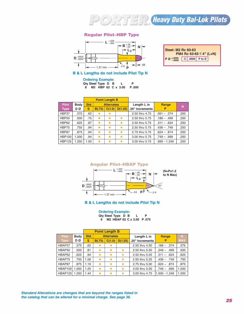
B & L Lengths do not include Pilot Tip N
Angular Pilot–HBAP Type
Ordering Example:Qty Steel Type D B L P
9 M2 HBAP 62 C x 3.00 P .575
Ordering Example:Qty Steel Type D B L P
8 M2 HBP 62 C x 3.00 P .500
Point Length B
Point Length B
.0005 P to D
Pilot Body Std. Alternates Length L in Range NType D Ø S B(.75) C(1.0) D(1.25) .25" Increments P
HBP37 .375 .62 • • 2.50 thru 4.75 .061 – .374 .250HBP50 .500 .75 • • • 2.50 thru 5.75 .186 – .499 .250HBP62 .625 .87 • • • 2.50 thru 5.75 .311 – .624 .250HBP75 .750 .94 • • • 2.50 thru 5.75 .436 – .749 .250HBP87 .875 .94 • • • 2.75 thru 5.75 .624 – .874 .250HBP100 1.000 .94 • • • 3.00 thru 5.75 .749 – .999 .250HBP125 1.250 1.00 • • • 3.00 thru 5.75 .999 –1.249 .250
Regular Pilot–HBP Type
B & L Lengths do not include Pilot Tip N
Steel: M2 Rc 60-63PM4 Rc 63-65 < 4" (L+N)
P Ø +.0005-.0000
Pilot Body Std. Alternates Length L in Range NType D Ø S B(.75) C(1.0) D(1.25) .25" Increments P MAX
HBAP37 .375 .62 • • 2.50 thru 4.50 .186 – .374 .375HBAP50 .500 .81 • • • 2.50 thru 5.50 .249 – .499 .500HBAP62 .625 .94 • • • 2.50 thru 5.25 .311 – .624 .625HBAP75 .750 1.06 • • • 2.50 thru 5.25 .436 – .749 .750HBAP87 .875 1.19 • • • 2.75 thru 5.00 .624 – .874 .875HBAP100 1.000 1.25 • • • 3.00 thru 5.00 .749 – .999 1.000HBAP125 1.250 1.44 • • • 3.00 thru 4.75 1.000 –1.249 1.250
Standard Alterations are changes that are beyond the ranges listed inthe catalog that can be altered for a minimal charge. See page 36.
(N=Px1.2to N Max)
26
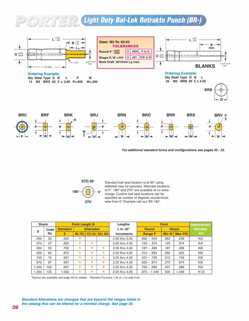
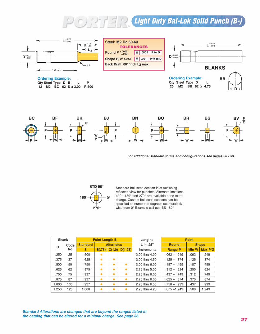
Light Duty Bal-Lok Retrakto Punch (BR-)
Ordering Example: Qty Steel Type D B L P W12 M2 BRO 62 C x 3.00 P=.600 W=.250
2
Ordering Example:Qty Steel Type D B L25 M2 BRB 50 C x 3.50
(Ref)
Standard ball seat location is at 90° usingreflected view for punches. Alternate locationsof 0°, 180° and 270° are available at no extracharge. Custom ball seat locations can bespecified as number of degrees counterclock-wise from 0° Example call out: BS 180°
*Ejector kits available see page 35 for details. Retrakto Punches 1.25 ø = no side hole.
Steel: M2 Rc 60-63TOLERANCES
Round P +.0005-.0000
Shape P, W ±.0005
Back Draft .001/inch L2 max..001 P,W to D
.0005 P to D
Shank Point Length B Lengths Point Replacement
D Code Standard Alternates L in .25" Round Shape RetraktoNo S B(.75) C(1.0) D(1.25) Increments Range P Min W Max P/G Kit*
.250 25 .500 • 2.00 thru 3.50 .062 – .249 .062 .249 K2I
.375 37 .625 • • 2.00 thru 4.00 .125 – .374 .125 .374 K4I
.500 50 .750 • • • 2.00 thru 4.00 .187 – .499 .187 .499 K6I
.625 62 .875 • • • 2.25 thru 4.00 .312 – .624 .250 .624 K6I
.750 75 .937 • • • 2.25 thru 4.00 .437 – .749 .312 .749 K9I
.875 87 .937 • • • 2.25 thru 4.00 .625 – .874 .375 .874 K9I1.000 100 .937 • • • 2.25 thru 4.00 .750 – .999 .437 .999 K9I1.250 125 1.000 • • • 2.25 thru 4.00 .875 – 1.249 .500 1.249 K12I
BLANKS
Standard Alterations are changes that are beyond the ranges listed inthe catalog that can be altered for a minimal charge. See page 36.
For additional standard forms and configurations see pages 30 - 33.
BRKBRF BRJ BRN BRO BRR BRS BRVBRC
27
Light Duty Bal-Lok Solid Punch (B-)
Ordering Example:Qty Steel Type12 M2 BC 62 S x 3.00 P.600
2
Ordering Example:Qty Steel Type D L25 M2 BB 62 x 4.75
Standard ball seat location is at 90° usingreflected view for punches. Alternate locationsof 0°, 180° and 270° are available at no extracharge. Custom ball seat locations can bespecified as number of degrees counterclock-wise from 0° Example call out: BS 180°
.001 P,W to D
Steel: M2 Rc 60-63TOLERANCES
Round P +.0005-.0000
Shape P, W ±.0005
Back Draft .001/inch L2 max.
.001 P,W to D
.0005 P to D
Shank Point Length B Lengths Point
D Code Standard Alternates L in .25" Round ShapeNo S B(.75) C(1.0) D(1.25) Increments Range P Min W Max P/G
.250 .500 • 2.00 thru 4.00 .062 – .249 .062 .249
.375 .625 • • 2.00 thru 4.50 .125 – .374 .125 .374
.500 .750 • • • 2.00 thru 6.00 .187 – .499 .187 .499
.625 .875 • • • 2.25 thru 5.00 .312 – .624 .250 .624
.750 .937 • • • 2.25 thru 6.00 .437 – .749 .312 .749
.875
25
37
50
62
75
87 .937 • • • 2.25 thru 6.00 .625 – .874 .375 .874
1.000 100 .937 • • • 2.25 thru 6.50 .750 – .999 .437 .999
1.250 125 1.000 • • • 2.25 thru 4.25 .875 –1.249 .500 1.249
BLANKS
Standard Alterations are changes that are beyond the ranges listed inthe catalog that can be altered for a minimal charge. See page 36.
BKBF BJ BN BO BR BS BVBC
For additional standard forms and configurations see pages 30 - 33.
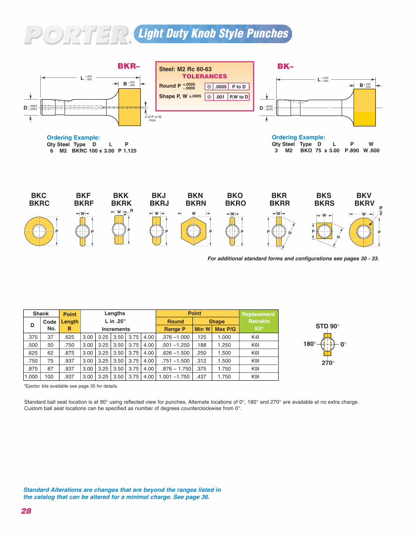
Light Duty Knob Style Punches
28
BK–
Ordering Example:Qty Steel Type
6 M2 BKRC 100 x 3.00 P 1.125
Ordering Example:Qty Steel Type3 M2 BKO 75 x 3.00 P.890 W .600
BKR–
*Ejector kits available see page 35 for details.
Steel: M2 Rc 60-63TOLERANCES
Round P +.0005-.0000
Shape P, W ±.0005
.001 P,W to D
.0005 P to D
Shank Point Lengths Point ReplacementCode Length L in .25" Round Shape Retrakto
DNo. B Increments Range P Min W Max P/G Kit*
.375 37 .625 3.00 3.25 3.50 3.75 4.00 .376 –1.000 .125 1.000 K4I
.500 50 .750 3.00 3.25 3.50 3.75 4.00 .501 –1.250 .188 1.250 K6I
.625 62 .875 3.00 3.25 3.50 3.75 4.00 .626 –1.500 .250 1.500 K6I
.750 75 .937 3.00 3.25 3.50 3.75 4.00 .751 –1.500 .312 1.500 K9I
K9I.875 87 .937 3.00 3.25 3.50 3.75 4.00 .876 – 1.750 .375 1.750
1.000 100 .937 3.00 3.25 3.50 3.75 4.00 1.001 –1.750 .437 1.750 K9I
BKKBKRK
BKJBKRJ
BKNBKRN
BKCBKRC
BKFBKRF
BKOBKRO
BKSBKRS
BKRBKRR
BKVBKRV
For additional standard forms and configurations see pages 30 - 33.
Standard ball seat location is at 90° using reflected view for punches. Alternate locations of 0°, 180° and 270° are available at no extra charge.Custom ball seat locations can be specified as number of degrees counterclockwise from 0°.
Standard Alterations are changes that are beyond the ranges listed inthe catalog that can be altered for a minimal charge. See page 36.
+.060+.060
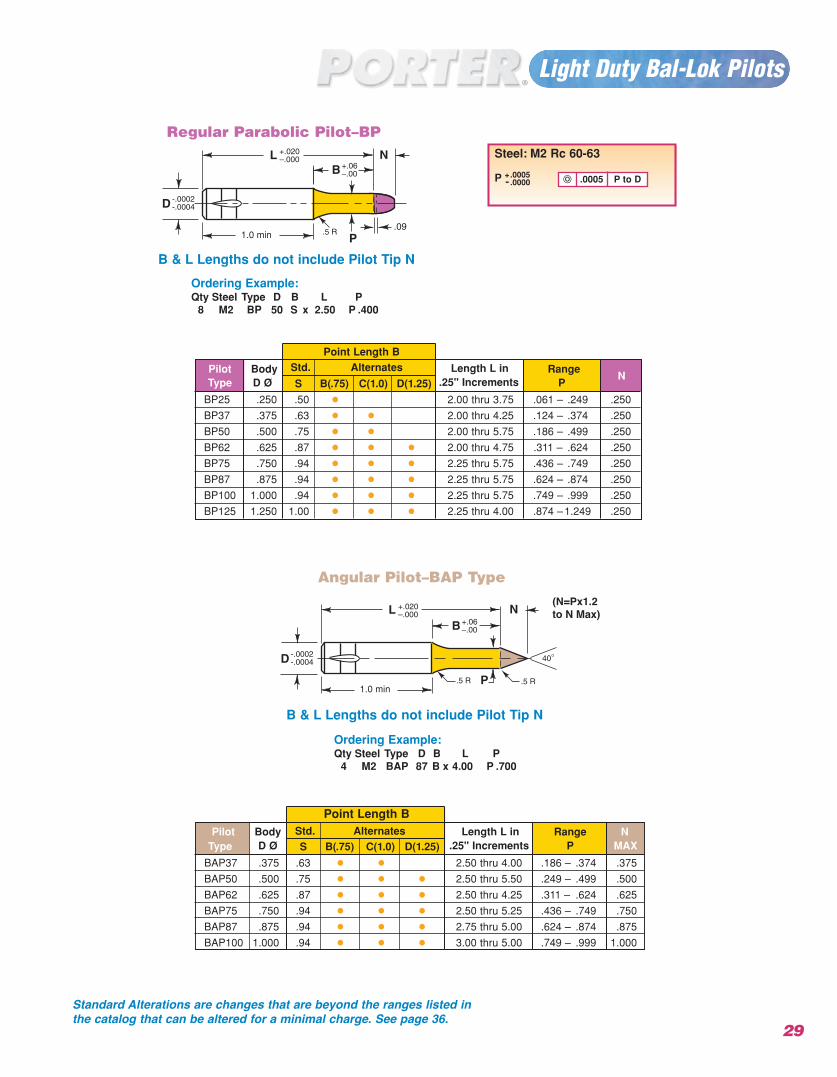
Light Duty Bal-Lok Pilots
29
1.0 min
1.0 min
B & L Lengths do not include Pilot Tip N
Regular Parabolic Pilot–BP
Angular Pilot–BAP Type
Ordering Example:Qty Steel Type D B L P
4 M2 BAP 87 B x 4.00 P .700
Ordering Example:Qty Steel Type D B L P
8 M2 BP 50 S x 2.50 P .400
Point Length B
Point Length B
B & L Lengths do not include Pilot Tip N
Pilot Body Std. Alternates Length L in RangeN
Type D Ø S B(.75) C(1.0) D(1.25) .25" Increments P
BP25 .250 .50 • 2.00 thru 3.75 .061 – .249 .250
BP37 .375 .63 • • 2.00 thru 4.25 .124 – .374 .250
BP50 .500 .75 • • 2.00 thru 5.75 .186 – .499 .250
BP62 .625 .87 • • • 2.00 thru 4.75 .311 – .624 .250
BP75 .750 .94 • • • 2.25 thru 5.75 .436 – .749 .250
BP87 .875 .94 • • • 2.25 thru 5.75 .624 – .874 .250
BP100 1.000 .94 • • • 2.25 thru 5.75 .749 – .999 .250
BP125 1.250 1.00 • • • 2.25 thru 4.00 .874 –1.249 .250
Pilot Body Std. Alternates Length L in Range NType D Ø S B(.75) C(1.0) D(1.25) .25" Increments P MAX
BAP37 .375 .63 • • 2.50 thru 4.00 .186 – .374 .375
BAP50 .500 .75 • • • 2.50 thru 5.50 .249 – .499 .500
BAP62 .625 .87 • • • 2.50 thru 4.25 .311 – .624 .625
BAP75 .750 .94 • • • 2.50 thru 5.25 .436 – .749 .750
BAP87 .875 .94 • • • 2.75 thru 5.00 .624 – .874 .875
BAP100 1.000 .94 • • • 3.00 thru 5.00 .749 – .999 1.000
Steel: M2 Rc 60-63
P +.0005- .0000 .0005 P to D
Standard Alterations are changes that are beyond the ranges listed inthe catalog that can be altered for a minimal charge. See page 36.
(N=Px1.2to N Max)
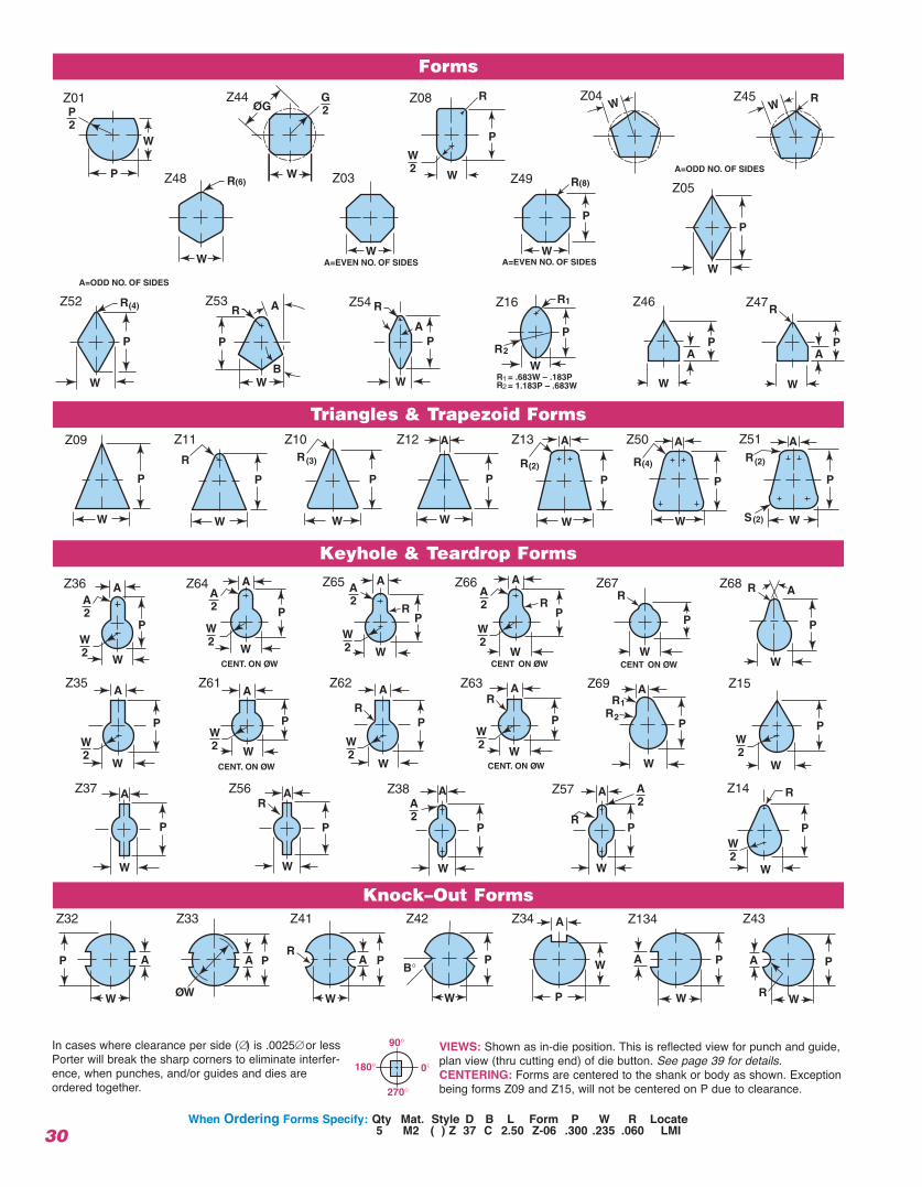
30When Ordering Forms Specify: Qty Mat. Style D B L Form P W R Locate
5 M2 ( ) Z 37 C 2.50 Z-06 .300 .235 .060 LMI
In cases where clearance per side (∅) is .0025∅ or lessPorter will break the sharp corners to eliminate interfer-ence, when punches, and/or guides and dies areordered together.
VIEWS: Shown as in-die position. This is reflected view for punch and guide,plan view (thru cutting end) of die button. See page 39 for details.CENTERING: Forms are centered to the shank or body as shown. Exceptionbeing forms Z09 and Z15, will not be centered on P due to clearance.
Forms
Triangles & Trapezoid Forms
Keyhole & Teardrop Forms
Knock–Out Forms
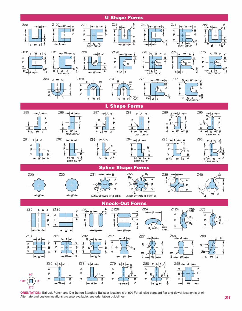
31ORENTATION: Bal-Lok Punch and Die Button Standard Ballseat location is at 90°. For all else standard flat and dowel location is at 0°.Alternate and custom locations are also available, see orientation guidelines.
U Shape Forms
L Shape Forms
Spline Shape Forms
Knock–Out Forms
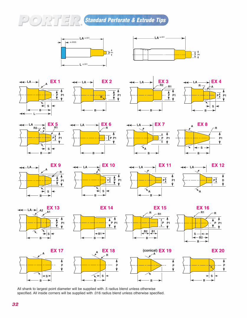
Standard Perforate & Extrude Tips
32
LA LA LA
LA
LA
LA
LA LA LA
LA LA
LA
All shank to largest point diameter will be supplied with .5 radius blend unless otherwisespecified. All inside corners will be supplied with .016 radius blend unless otherwise specified.
LA ±.001 ±.001
L ±.001
±.0005
LA
D
Standard Punch Shear
33
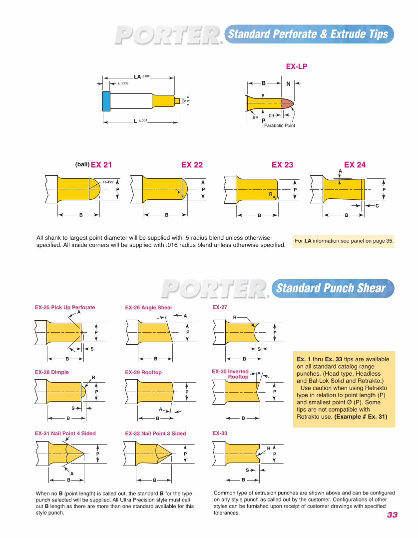
Ex. 1 thru Ex. 33 tips are availableon all standard catalog rangepunches. (Head type, Headlessand Bal-Lok Solid and Retrakto.)
Use caution when using Retraktotype in relation to point length (P)and smallest point Ø (P). Sometips are not compatible withRetrakto use. (Example # Ex. 31)
When no B (point length) is called out, the standard B for the typepunch selected will be supplied. All Ultra Precision style must callout B length as there are more than one standard available for thisstyle punch.
Common type of extrusion punches are shown above and can be configuredon any style punch as called out by the customer. Configurations of otherstyles can be furnished upon receipt of customer drawings with specified tolerances.
Standard Perforate & Extrude Tips
All shank to largest point diameter will be supplied with .5 radius blend unless otherwisespecified. All inside corners will be supplied with .016 radius blend unless otherwise specified.
For LA information see panel on page 35.
LA ±.001
L ±.001
±.0005
EX-LP
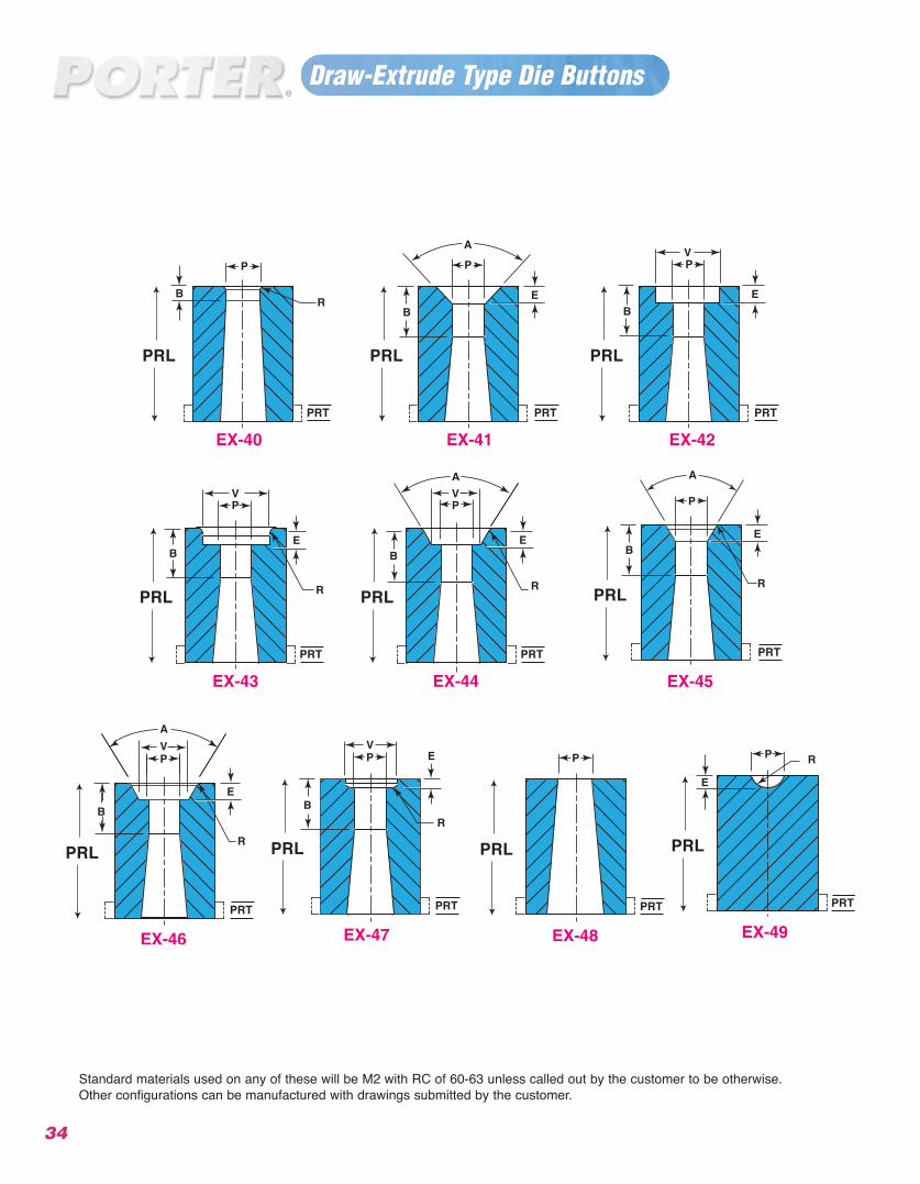
Standard materials used on any of these will be M2 with RC of 60-63 unless called out by the customer to be otherwise. Other configurations can be manufactured with drawings submitted by the customer.
Draw-Extrude Type Die Buttons
34
PRL
PRT
PRL
PRT
PRL
PRL
PRL
PRL
PRL
PRL
PRT
PRL
PRT
PRL
PRT
PRT
PRT
PRT
PRT
PRT
35
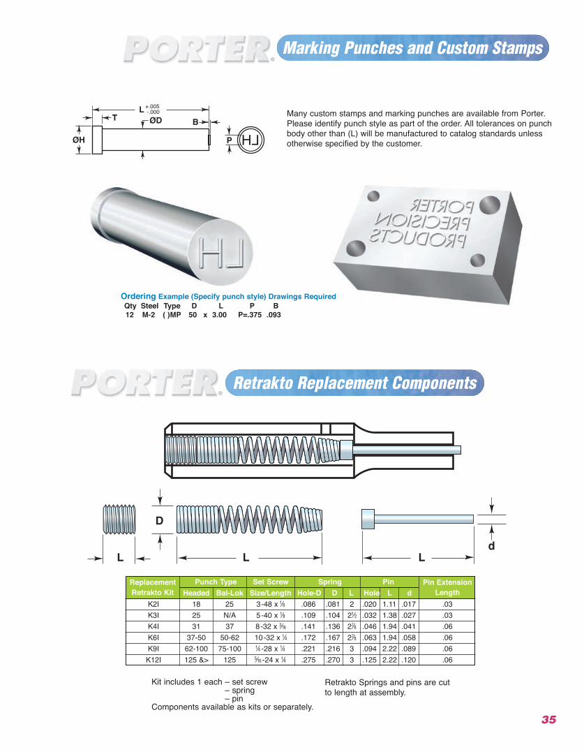
Marking Punches and Custom Stamps
Retrakto Replacement Components
LHP
TL
ØH
ØD+.005 -.000
BMany custom stamps and marking punches are available from Porter.Please identify punch style as part of the order. All tolerances on punchbody other than (L) will be manufactured to catalog standards unlessotherwise specified by the customer.
Kit includes 1 each – set screw– spring– pin
Components available as kits or separately.
Retrakto Springs and pins are cutto length at assembly.
Replacement Punch Type Set Screw Spring Pin Pin ExtensionRetrakto Kit Headed Bal-Lok Size/Length Hole-D D L Hole L d Length
K2I 18 25 3-48 x r .086 .081 2 .020 1.11 .017 .03K3I 25 N/A 5-40 x r .109 .104 2q .032 1.38 .027 .03K4I 31 37 8-32 x o .141 .136 2u .046 1.94 .041 .06K6I 37-50 50-62 10-32 x w .172 .167 2u .063 1.94 .058 .06K9I 62-100 75-100 w -28 x w .221 .216 3 .094 2.22 .089 .06K12I 125 &> 125 p -24 x w .275 .270 3 .125 2.22 .120 .06
Ordering Example (Specify punch style) Drawings RequiredQty Steel Type D L P B12 M-2 ( )MP 50 x 3.00 P=.375 .093
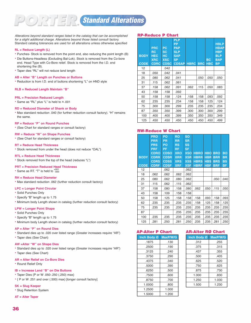
Alterations beyond standard ranges listed in the catalog that can be accomplishedfor a slight additional charge. Alterations beyond those listed consult factory.Standard catalog tolerances are used for all alterations unless otherwise specified
RL = Reduce Length (L)• Punches- Stock is removed from the point end, also reducing the point length (B)• Die Buttons-Headless (Excluding Bal-Lok). Stock is removed from the Co-bore
end. Head Type with Co-Bore relief. Stock is removed from the I.D. end shortening the (B).
• Taper dies “RL” will not reduce land length
AB = Alter “B” Length on Punches or Buttons• Reduction is from I.D. end of buttons shortening “L” on HND style
RLB = Reduced Length Maintain “B”
PRL = Precision Reduced Length• Same as “RL” plus “L” is held to ±..001
RD = Reduced Diameter of Shank or Body• Max standard reduction .040 (for further reduction consult factory). “H” remains
the same.
RP = Reduce “P” on Round Punches• (See Chart for standard ranges or consult factory)
RW = Reduce “W” on Shape Punches • (See Chart for standard ranges or consult factory)
RT = Reduce Head Thickness• Stock removed from under the head (does not reduce “OAL”)
RTL = Reduce Head Thickness• Stock removed from the top of the head (reduces “L”)
PRT = Precision Reduced Head Thickness• Same as RT. “T” is held to
RH = Reduce Head Diameter• Max standard reduction .062 (further reduction consult factory)
LPC = Longer Point Circular• Solid Punches Only• Specify “B” length up to 1.75• Minimum body Length shown in catalog (further reduction consult factory)
LPW = Longer Point Shape• Solid Punches Only• Specify “B” length up to 1.75• Minimum body Length shown in catalog (further reduction consult factory)
AP = Alter “P” on Round Dies• Standard dies up to .020 over listed range (Greater increases require “AR”)• Taper dies (See Chart)
AW =Alter “W” on Shape Dies• Standard dies up to .020 over listed range (Greater increases require “AR”)• Taper dies (See Chart)
AR = Alter Relief on Co-Bore Dies• Round Relief Only
IB = Increase Land “B” on Die Buttons• Taper Dies {P or W .050-.250 (.250) max}• { P or W .251 and over (.500) max} [longer consult factory]
SK = Slug Keeper• Slug Retention System
AT = Alter Taper
Standard Alterations
36
12 .062 .06218 .062 .062 .062 .06225 .080 .062 .080 .062 .050 .04031 .115 .062 .115 .06237 .158 .080 .158 .080 .062 .050 .115 .05043 .158 .109 .158 .15850 .158 .125 .158 .158 .158 .093 .158 .09362 .235 .235 .235 .235 .158 .125 .158 .12575 .235 .235 .235 .235 .235 .235 .235 .23587 .235 .235 .235 .235 .235 .235100 .235 .235 .235 .235 .235 .235 .235 .235125 .281 .250 .281 .250 .235 .235 .281 .250
RW-Reduce W Chart
Inch Body Ø MaxP/W/G.1875 .130.2500 .190.3125 .240.3750 .290.4375 .340.5000 .390.6250 .500.7500 .600.8750 .700
1.0000 .8001.2500 1.0001.5000 1.200
RP-Reduce P Chart
Inch Body Ø MaxP/W/G.312 .255.375 .315.437 .355.500 .405.625 .520.750 .625.875 .730
1.000 .8301.250 1.0301.500 1.230
AP-Alter P Chart AR-Alter RØ Chart
PLPPP HBLP
PRC PC PAP HBAPRC SC SLP HBP
BODY HEC HC SAP BLPXRC XSC SP BC BAP
CODE CDRC CDSC CDSAP HBRC BRC HBC BP12 .04218 .050 .042 .04125 .080 .062 .041 .050 .050 .05031 .115 .062 .06137 .158 .062 .091 .062 .115 .050 .08343 .158 .158 .09250 .158 .158 .124 .158 .158 .093 .09262 .235 .235 .234 .158 .158 .125 .12475 .300 .300 .299 .235 .235 .235 .23487 .350 .350 .399 .300 .300 .300 .299100 .400 .400 .399 .350 .350 .350 .349125 .450 .450 .450 .450 .450 .450 .499
PRO PO RO SOPRR PR RR SRPRS PO RS SSPRF PF RF SFCDRO CDSO XRO XSO HBRO HBO BRO BO
BODY CDRR CDSR XRR XSR HBRR HBR BRR BRCDRS CDSS XRS XSS HBRS HBS BRS BS
CODE CDRF CDSF XRF XSF HBRF HBF BRF BF+001-000
37
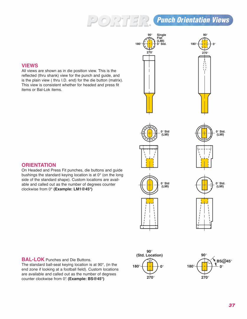
Punch Or entation Vii ews
VIEWSAll views are shown as in die position view. This is thereflected (thru shank) view for the punch and guide, andis the plain view ( thru I.D. end) for the die button (matrix).This view is consistent whether for headed and press fititems or Bal-Lok items.
ORIENTATIONOn Headed and Press Fit punches, die buttons and guidebushings the standard keying location is at 0° (on the longside of the standard shape). Custom locations are avail-able and called out as the number of degrees counterclockwise from 0° (Example: LM1@45°)
BAL-LOK Punches and Die Buttons. The standard ball-seat keying location is at 90°, (in theend zone if looking at a football field). Custom locationsare available and called out as the number of degreescounter clockwise from 0°. (Example: BS@45°)
38
Flat Locations-Headed Punches, Die Buttons & Guide
All above locating methods are supplied atstandard location (0•) “Alternate locationsare available at no extra charge” Call out(LM1@90)
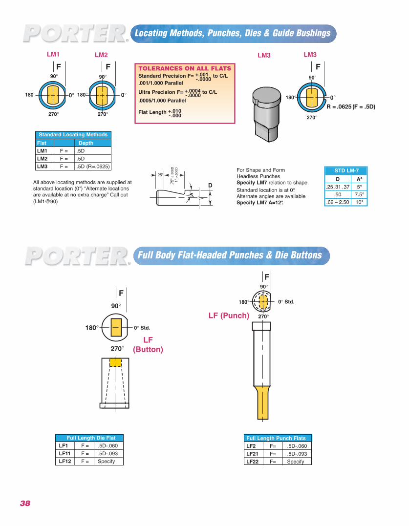
Full Length Punch FlatsLF2 F= .5D-.060LF21 F= .5D-.093LF22 F= Specify
Full Body Flat-Headed Punches & Die Buttons
Full Length Die FlatLF1 F = .5D-.060LF11 F = .5D-.093LF12 F = Specify
.
.
Flat DepthLM1 F = .5DLM2 F = .5DLM3 F = .5D (R=.0625)
Standard Locating Methods
Locating Methods, Punches, Dies & Guide Bushings
LM3
R = .0625 (F = .5D)
LM3
F F FLM2LM1
TOLERANCES ON ALL FLATSStandard Precision F= +.001 to C/L-.0000001/1.. 000 Parallel
Ultra Precision F= +.0004 to C/L- .00000005/1.. 000 Parallel
Flat Length +.010- .000
D A°.25 .31 ..37 5°
.50 7.5°.62 – 2.50 10°
STD LM-7For Shape and Form Headless Punches Specify LM7 relation to shape.Standard location is at 0°.Alternate angles are available Specify LM7 A=12°.
LF
F
F
(Button)
LF (Punch)
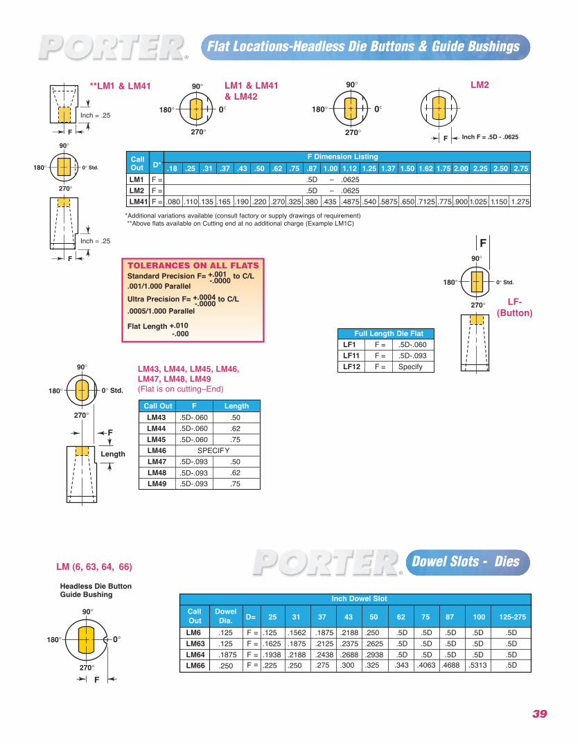
Call F Dimension ListingOut D* .18 .25 .31 .37 .43 .50 .62 .75 .87 1.00 1.12 1.25 1.37 1.50 1.62 1.75 2.00 2.25 2.50 2.75LM1 F = .5D – .0625LM2 F = .5D – .0625LM41 F = .080 .110 .135 .165 .190 .220 .270 .325 .380 .435 .4875 .540 .5875 .650 .7125 .775 .900 1.025 11. 50 1.275
Flat Locations-Headless Die Buttons & Guide Bushings
LM43, LM44, LM45, LM46, LM47, LM48, LM49(Flat is on cutting–End)
LM2
Inch Dowel SlotCall DowelOut Dia. D= 25 31 37 43 50 62
LM6 .125 F = .125 .1562 .1875 .2188 .250 .5DLM63 .125 F = .1625 .1875 .2125 .2375 .2625 .5DLLM66
M64 ..2501875 F
F==
.
.2251938 .
.2502188 .2438 .2688 .2938 .5D
75
.5D
.5D
.5D
87
.5D
.5D
.5D
100
.5D
.5D
.5D
125-275
.5D
.5D
..275 .300 .325 .343 .4063 .4688 .5313 .5D
5D
Full Length Die FlatLF1 F = .5D-.060LF11 F = .5D-.093LF12 F = Specify
**LM1 & LM41
*Additional variations available (consult factory or supply drawings of requirement)**Above flats available on Cutting end at no additional charge (Example LM1C)
Call Out F LengthLM43 .5D-.060
.5D-.060
.5D-.060
.5D-.093
.5D-.093
.5D-.093
.50LM44 .62LM45 .75LM46 SPECIFYLM47 .50LM48 .62LM49 .75
LM1 & LM41& LM42
39
TOLERANCES ON ALL FLATSStandard Precision F= +.001 to C/L-.0000.001/1.000 ParallelUltra Precision F= +.0004 to C/L-.0000.0005/1.000 Parallel
Flat Length +.010-.000
Dowel Slots - DiesLM (6, 63, 64, 66)
LF-(Button)
F
F
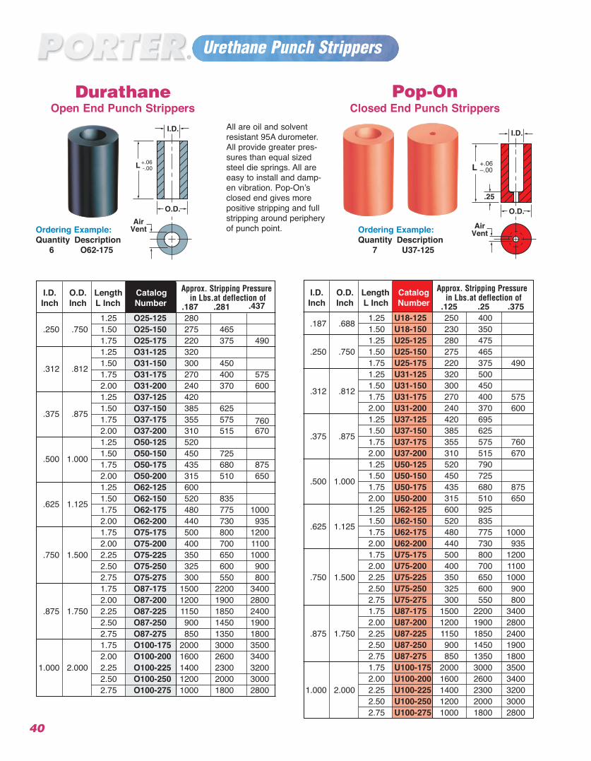
Closed End Punch StrippersDurathane
Open End Punch Strippers
Approx. Stripping PressureI.D. O.D. Length Catalogin Lbs.at deflection ofInch Inch L Inch Number .125 .25 .375
1.25 U18-125 250 400.187 .688 1.50 U18-150 230 3501.25 U25-125 280 475
.250 .750 1.50 U25-150 275 4651.75 U25-175 220 375 4901.25 U31-125 320 5001.50 U31-150 300 450.312 .812 1.75 U31-175 270 400 5752.00 U31-200 240 370 6001.25 U37-125 420 6951.50 U37-150 385 625.375 .875 1.75 U37-175 355 575 7602.00 U37-200 310 515 6701.25 U50-125 520 7901.50 U50-150 450 725.500 1.000 1.75 U50-175 435 680 8752.00 U50-200 315 510 6501.25 U62-125 600 9251.50 U62-150 520 835.625 1.125 1.75 U62-175 480 775 10002.00 U62-200 440 730 9351.75 U75-175 500 800 12002.00 U75-200 400 700 1100
.750 1.500 2.25 U75-225 350 650 10002.50 U75-250 325 600 9002.75 U75-275 300 550 8001.75 U87-175 1500 2200 34002.00 U87-200 1200 1900 2800
.875 1.750 2.25 U87-225 1150 1850 24002.50 U87-250 900 1450 19002.75 U87-275 850 1350 18001.75 U100-175 2000 3000 35002.00 U100-200 1600 2600 3400
1.000 2.000 2.25 U100-225 1400 2300 32002.50 U100-250 1200 2000 30002.75 U100-275 1000 1800 2800
Ordering Example: Quantity Description
7 U37-125
Urethane Punch Strippers
Ordering Example: Quantity Description
6 O62-175
40
All are oil and solventresistant 95A durometer.All provide greater pres-sures than equal sizedsteel die springs. All areeasy to install and damp-en vibration. Pop-On’sclosed end gives morepositive stripping and fullstripping around peripheryof punch point.
Pop-On
Approx. Stripping PressureI.D. O.D. Length Catalogin Lbs.at deflection ofInch Inch L Inch Number .187 .281 .437
1.25 O25-125 280.250 .750 1.50 O25-150 275 465
1.75 O25-175 220 375 4901.25 O31-125 3201.50 O31-150 300 450.312 .812 1.75 O31-175 270 400 5752.00 O31-200 240 370 6001.25 O37-125 4201.50 O37-150 385 625.375 .875 1.75 O37-175 355 575 7602.00 O37-200 310 515 6701.25 O50-125 5201.50 O50-150 450 725.500 1.000 1.75 O50-175 435 680 8752.00 O50-200 315 510 6501.25 O62-125 6001.50 O62-150 520 835.625 1.125 1.75 O62-175 480 775 10002.00 O62-200 440 730 9351.75 O75-175 500 800 12002.00 O75-200 400 700 1100
.750 1.500 2.25 O75-225 350 650 10002.50 O75-250 325 600 9002.75 O75-275 300 550 8001.75 O87-175 1500 2200 34002.00 O87-200 1200 1900 2800
.875 1.750 2.25 O87-225 1150 1850 24002.50 O87-250 900 1450 19002.75 O87-275 850 1350 18001.75 O100-175 2000 3000 35002.00 O100-200 1600 2600 3400
1.000 2.000 2.25 O100-225 1400 2300 32002.50 O100-250 1200 2000 30002.75 O100-275 1000 1800 2800
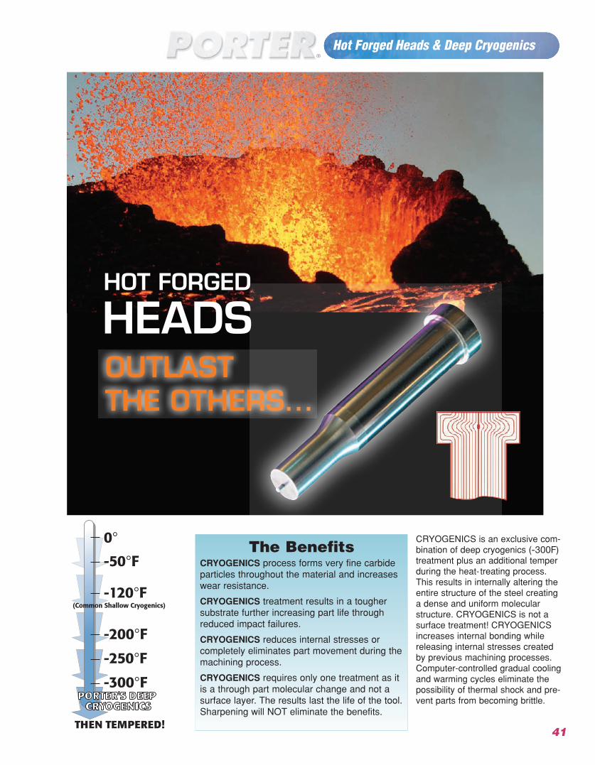
Hot Forged Heads & Deep Cryogenics
41
HOT FORGED
HEADSOUTLASTTHE OTHERS...
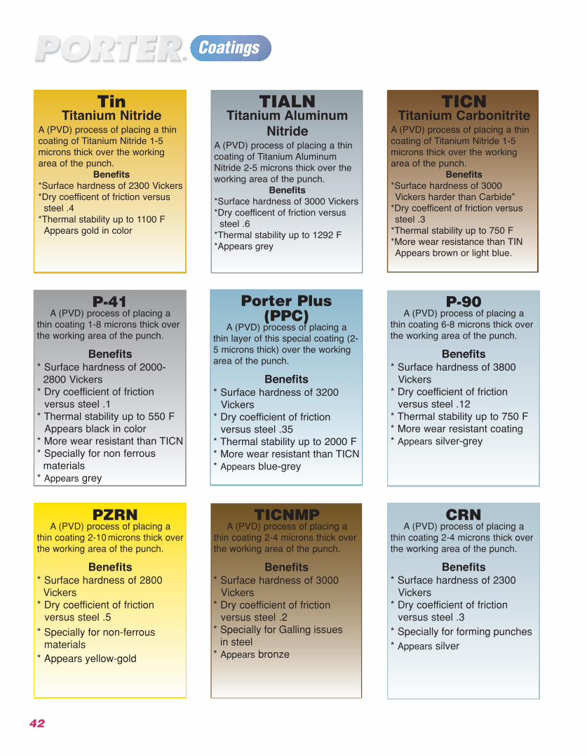
TinTitanium Nitride
A (PVD) process of placing a thincoating of Titanium Nitride 1-5microns thick over the workingarea of the punch.
Benefits*Surface hardness of 2300 Vickers*Dry coefficent of friction versus
steel .4*Thermal stability up to 1100 F
Appears gold in color
TICNTitanium Carbonitrite
A (PVD) process of placing a thincoating of Titanium Nitride 1-5microns thick over the workingarea of the punch.
Benefits*Surface hardness of 3000Vickers harder than Carbide”
*Dry coefficent of friction versus steel .3
*Thermal stability up to 750 F *More wear resistance than TINAppears brown or light blue.
TIALNTitanium Aluminum
NitrideA (PVD) process of placing a thincoating of Titanium AluminumNitride 2-5 microns thick over theworking area of the punch.
Benefits*Surface hardness of 3000 Vickers*Dry coefficent of friction versus
steel .6*Thermal stability up to 1292 F *Appears grey
Porter Plus (PPC)
A (PVD) process of placing athin layer of this special coating (2-5 microns thick) over the workingarea of the punch.
Benefits* Surface hardness of 3200
Vickers* Dry coefficient of friction
versus steel .35* Thermal stability up to 2000 F * More wear resistant than TICN * Appears blue-grey
P-41A (PVD) process of placing a
thin coating 1-8 microns thick overthe working area of the punch.
Benefits* Surface hardness of 2000-
2800 Vickers* Dry coefficient of friction
versus steel .1* Thermal stability up to 550 F
Appears black in color* More wear resistant than TICN * Specially for non ferrous
materials* Appears grey
P-90A (PVD) process of placing a
thin coating 6-8 microns thick overthe working area of the punch.
Benefits* Surface hardness of 3800
Vickers* Dry coefficient of friction
versus steel .12* Thermal stability up to 750 F
* More wear resistant coating * Appears silver-grey
Coatings
42
TICNMP
Benefits* Surface hardness of 3000
Vickers* Dry coefficient of friction
versus steel .2* Specially for Galling issues
in steel
* Appears bronze
PZRNA (PVD) process of placing a
thin coating 2-10 microns thick overthe working area of the punch.
Benefits* Surface hardness of 2800
Vickers* D
*
*
Specially for non-ferrousmaterialsAppears yellow-gold
ry coefficient of friction versus steel .5
CRNA (PVD) process of placing a
thin coating 2-4 microns thick overthe working area of the punch.
A (PVD) process of placing athin coating 2-4 microns thick overthe working area of the punch.
Benefits* Surface hardness of 2300
Vickers* D
* Specially for forming punches
ry coefficient of friction versus steel .3
* Appears silver
43
Policy / Items and Conditions
PolicyPorter Precision Products guarantees its products to meet catalog specifications which are inter-changeable and equivalent to I.S.O. standards. Print items and special description call-outs will bemanufactured to the customer’s specifications. No other warranties are expressed or implied.
All dimensions not specifically toleranced will be manufactured to industry (our Catalog) standards,regardless of the decimal place call-out. To eliminate misunderstandings, include tolerance charts onyour prints or specifically tolerance critical dimensions.
Steel type is to be specified by the customer. If not specified, we will supply the first material listedin the catalog. It is always best to include your material choice in the part call-out as shown in theordering examples.
Terms & ConditionsPrices- Net each and subject to change without notice.
Minimum Order Charge-There is no minimum order charge on manufactured items.
Terms-Net 30 Days, F.O.B. Shipping pointwe also accept American Express, Master Card, and VisaCredit- Orders are subject to the approval of our credit department. To expedite new accounts, furnishbank reference and three supplier references.
Returns- Credit claims for our manufactured items must be made within 45 days of shipment date.Stock blanks are returnable for credit less a 25% restocking fee. If they are exchanged for items ofequal or greater value they can be returned for full credit. All items altered by us to the customer’sspecifications are the property of the buyer and are not returnable unless they do not meet catalog orprint tolerances. Any item that has been altered by the customer is the said customer’s responsibilityand is for no reason returnable.
Over/Under Shipments- Manufactured products can vary up to 10% of the quantity ordereddepending on the complexity of the part. If no variation is acceptable this information must be suppliedto us at the time of quoting.
Cancellation- The customer will be responsible for a pro-rated charge to cover any work completedprior to cancellation.
Infringements- Customer shall assume all responsibility and undertake the defense of all lawsuitsfor infringements on patents brought against Porter Precision Products for the manufacture of prod-ucts named in an order when said products are made according to drawings, samples, and/or descrip-tions that have been supplied by the customer.Items supplied but not manufactured by us- All policies/terms & conditions set forth by the manu-facturer of said items are applicable. Contact Porter Precision Products for information regarding vari-ous policies.
Corporate Office & Manufacturing Plant2734 Banning Rd., Cincinnati, Ohio 45253-8706
Ph: (513) 923-3777 • Fax: (513) 923-1111Toll Free (800) 543-7041
Georgia Manufacturing Plant660 James Rd., Alpharetta, Ga. 30004
Ph: (770) 751-7234 • Fax: (770) 751-7238Toll Free: (800) 437-5185
Canada Plant30 Duke Street West, Suite #503
Kitchener, Ontario, Canada N2H 3W5Ph: (519) 746-3130 • Fax: (519) 746-6960
Toll Free: [email protected]
World Class Products That Perform!
PORTER PRECISION PRODUCTS CO.
www.porterpunch.com