Embed Size (px)
DESCRIPTION
Architecture Portfolio
Citation preview

arch. PORTFOLIOJesus Armando Fernandez • 2012 B.Arch University of Oregon

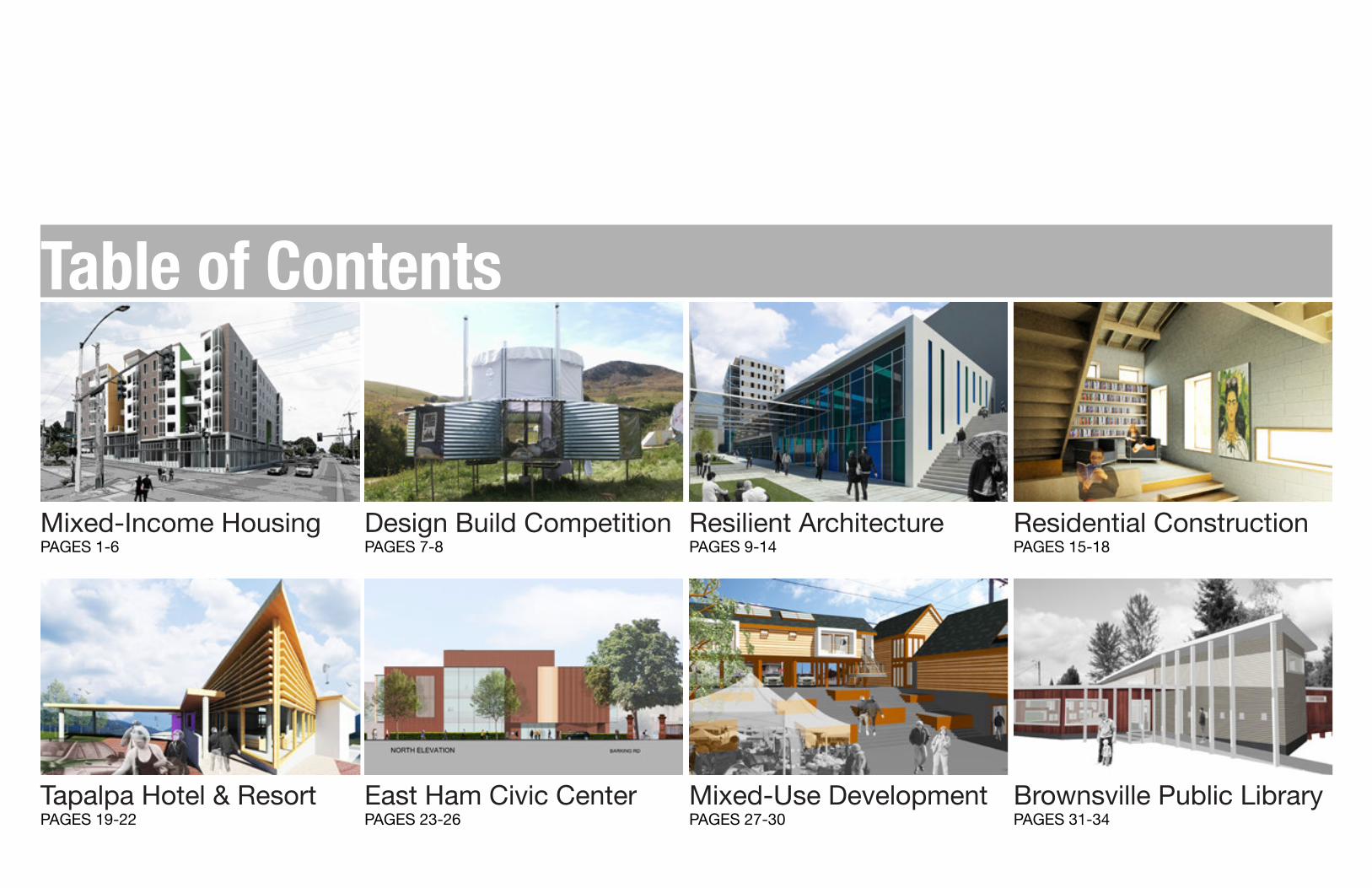
Resilient ArchitecturePAGES 9-14
Design Build CompetitionPAGES 7-8
Residential ConstructionPAGES 15-18
Tapalpa Hotel & ResortPAGES 19-22
East Ham Civic CenterPAGES 23-26
Mixed-Use DevelopmentPAGES 27-30
Brownsville Public LibraryPAGES 31-34
Mixed-Income HousingPAGES 1-6
Table of Contents

21st Century NeighborhoodMixed-Income Housing
Yesler Terrace, WAArch 584 • Micheal Pyatok • Winter/Spring 2012
Media: Revit, Photoshop, Illustrator, Physical Models
Site Description: Yesler Terrace is located in central Seattle, WA. A place with a rich history and a beautiful location but throughout the years has lost a lot of its attraction. In 1934 Yesler Terrace was listed as Seattle’s worst slum in a Federal survey. Various changes have been made since the 866 original low income hous-ing units were built in 1942, but beginning in 2006 the Seattle Housing Authority (SHA) has been considering the redevelopment of Yesler Terrace. �e studio was split into 17 blocks. Every student was assigned a block and asked to develop a speci�c project for mixed income housing. �e unit requirements range from 150 units to 300 units depending on the site, 60% market rate with 40% a�ordable.
Design Statement: It has been a challenge to incorporate mixed income housing in the U.S. �e site gives the opportunity for a series of gardens that are private to each individual building but are visually shared with the whole development. In my site I have Student housing along with a�ordable and market rate. �e site is near two colleges and it lends to even more diverse mixed income housing. �e unobstructed views also allow for the creation of expanding on the shared gardens idea to creating internal and external view corridors.
1

2

BOREN AVE
YESLER WAY
FIR ST
12 TH AVE
H AVE
H A
1ST FL PLAN ABOVE PODIUM5 20
10 50PARKING GARAGE PLAN 5
10
20
50
Massing Study
3

4
2.2 acres
50’ elevation change
Elev. 234
Elev. 240
Elev. 253
50’ max50’ max50’ max50’ max50’ max50’ max50’ max50’ max50’ max50’ max50’ max50’ max50’ max50’ max50’ max50’ max
Site Podiums 5-Story Limit Courtyards View Corridors Program
market rateaffordablestudent

Overall Form
Pop-Outs
Circulation Screen
Student Housingdesigning through perspectives
5

Affordable Housingdesigning through perspectives
6
Overall Form
Pop-Outs
Circulation Screen

7
1st Place “Most Sustainable” 2007 Design Village Competition
San Luis Obispo, CAEl Camino College
Steel & Plywood Structure
Project Description: “Design Village challenges participants to adapt to Poly Canyon’s sun, wind, rain, and topography by creating a temporary structure for you entire team for the weekend. �is year’s theme:
LIVING : MACHINE building the space between
explores the gap between the machine and human existence.”
Concept Statement: �e relationship between technology and man has become increasingly intertwined in today’s day and age. We believe that this relationship is similar to the func-tion of a gear. Gears enable machines to move and carry out their objectives in the same way that technology has facilitated mans ability to carry out it’s daily functions. Sustainable architecture is a technological approach to design that creates an environmental impact by enhancing e�ciency and moderation in the use of materials, energy, and the development of space. With the habitual gear we tried to incorporate some of these ideas to design a more e�cient structure.
water storage
sleeping area
wind catcher
water catchment
adjustable stilts

8
CONSTRUCTION PROCESS

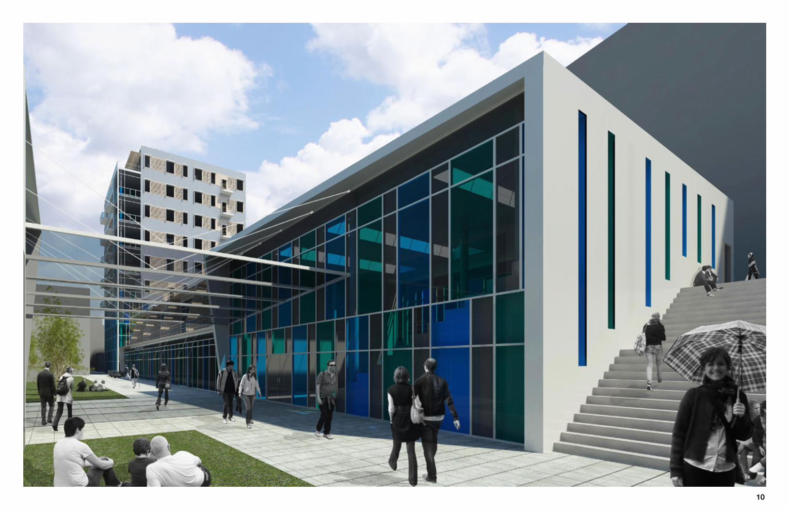
Industrial PromenadeResilient Architecture
Whitechapel, London, UKArch 484 • Howard Davis • Fall 2011
Media: Revit, Photoshop, Illustrator, Physical Models
Project Description: Whitechapel is an inner city in the London Borough of Tower Ham-lets. It is east of the �nancial district in London and has been home to many immigrants including Irish, Jewish, Russian, Chinese, and Bangladeshi. Currently, Bangladeshis make up 52% of Whitechapel and the in�uence of the Muslim community is visible through the East London Mosque (1910) and the London Muslim Centre (2004) located on Whi-techapel Road. With the expensive standard of living in London and the scarce amount of space, there is a growing need for Live + Work spaces. Most people with businesses already live at their shops/stores or at least in close proximity. One thing that is evident is the opportunity for shared production/storage spaces to help up and coming businesses grow as well as to allow for more dwelling units to be built around the workshops, ware-houses, and retail spaces.
Concept Statement: Our site is very constricted for 60,000 square feet of space. Not only is sunlight very scarce throughout the year in London, but there are surrounding high-rise apartment buildings that block most ovvf the sunlight the site would otherwise have. �e two most important concerns of mine were access and daylight. With such a constricted space the idea was to maximize daylight for the workshops and daylight for the dwelling units by creating uninterrupted spaces around the building footprint. In these spaces I’ve installed promenades, public gardens and service circulation. Adding color to the space was also a way to bring more life and energy into the space.
9
10

SPACE TYPE UNIT AREA NO. TOTAL AREADwelling Unit 1 500 square feet 14 7000 square feet Dwelling Unit 2 1000 square feet 8 8000 square feet Live + Work Units 1200 square feet 7 8400 square feet Small Workshops 1600 square feet 7 11200 square feet Shared Production & Storage 4800 square feet 1 4800 square feet Exhibition Space 2000 square feet 1 2000 square feet Forum (100 people) 2000 square feet 1 2000 square feetRestaurant 2000 square feet 1 2000 square feetRetail Vary 6 5200 square feet
TOTAL (without circulation & outdoor space)Bike Storage 600 square feet 1 600 square feet
PROGRAM
51200 square fee
SECTION A-A
Massing Study
SECTION B-B
123
3
3
3
3
2
2
2
2
2
3 3 3 3
3
3
1
1
1
1
14
4 7 4 4 4
5
5
5
5
2
1
1
1
1
1
6789
10
11

U P
N
A
B
B
A
7
4
4
9
9
6
4
9
9
9
9
8
4
4
5
12

UPUP
3
3
1
1
1
1
2
2
13

STRUCTURE COLOR RIBBON FENESTRATION
14

Fernandez ResidenceResidential Construction
Eugene, ORAdvanced Technology • Rob Thallon • Spring 2011
Media: Revit, AutoCAD, Illustrator, Laser Cutter
Project Description: Design a 500 square foot cabin in the quiet hills of Eugene, OR. �is course was not a studio but an advance technology course focused on producing construc-tion documents. �e size of the project presented many challenges to produce a relaxing retriet for two people. I decided to convert the space into a lo� to get more out of the square footage. �e high ceiling created by the lo� make the space feel larger than the numbers would suggest. To create more depth, various levels are created to de�ne usage and create useful transition spaces.
15
ROOF FRAMING PLAN
1/4”=1’-0”3FIRST FLOOR PLAN
1/4”=1’-0”3
SITE PLAN
1/16”=1’-0”1
70.0’
70.0’
80.0
’
RESIDENCEFIN. FL. 103.0
CONC. DRIVEWAY
5’ SIDEWALK
PORCHFIN. FL.101.0
100.0
101.0
102.0
103.0
104.0
103.0
104.0
102.0
101.0
100.0
SEWER LINE
WAT
ER L
INE
WAT
ER
MTR
ELEC
. MTR
N
N N
12
4
CROSS SECTION
1/2”=1’-0”5
EAST ELEVATION
1/4”=1’-0”7SOUTH ELEVATION
1/4”=1’-0”6
12
4
JAF
THE
500
RESI
DEN
CE
JESUS A. FERNANDEZ
JUNE 9, 2011
05001102
Owner:Summer E. Carrillo
Project Architect: Jesus A. Fernandez
Project Location: 550 W 25TH PLACEEUGENE, OR 97405
ARCHITECTS
KITCHEN ELEVATION
1/2”=1’-0”2
UP
UP
UP
R
A15
READING RM.
PORCH
DN
A15
BEDROOM DECK
WALL DETAIL SECTION
1-1/2”=1’-0”1
6 K GUTTER
CONTINUOUS 2” X 12” FASCIA BOARD
FURRING STRIPS & 1/2” PLYWOOD SHEATHING OVER EXPOSED EAVE
2” X 8” FRIEZE BLOCK
1” THICK CORRUGATED METAL ROOFING
4” RIGID INSULATION
2” X 6” BLOCKING
4” X 8” BEAM
VAPOR BARRIER BETWEEN INSULATION & 1/2” PLYWOOD SHEATHING
2” X 8” ROOF RAFTERS
FINISH WOOD CEILING PANELS
NAILING BLOCK FOR FINISH WALL
1/2” PLYWOOD SHEATHING W/FINISH WALL
R-8 (2) BATT INSULATION
2” X 8” TOP PLATE W/ANCHOR BOLT
1/2” VERTICAL REBAR EVERY 36”
8” X 8” X 16” CMU BLOCK W/BOND
4” RIGID INSULATION BETWEEN STRUCTURAL CMU & CMU VENEER
CMU VENEER
1/2” HORIZONTAL REBAR AS REQUIRED BY ENGINEERING
2” RIGID INSULATION
WOOD FLOOR FINISH
6” RADIATING HEATING SLAB
BACKFILL
8” X 24” FOOTING
BACKFILL AND DRAINAGE
FOUNDATION/FLOOR FRAMING PLAN
1/4”=1’-0”2
N
ROOF FRAMING PLAN
1/4”=1’-0”3
JAF
THE
500
RESI
DEN
CE
JESUS A. FERNANDEZ
JUNE 9, 2011
05001102
Owner:Summer E. Carrillo
Project Architect: Jesus A. Fernandez
Project Location: 550 W 25TH PLACEEUGENE, OR 97405
ARCHITECTS
2
WOOD STOP
STRUCTURAL CMU
WOOD BACKHAND
WOOD JAMB
URATHANE - FOAM OR BATT INSULATION
FLASHING @ HEAD- APPLIED BETWEEN
STURCTURAL WASLL AND INSULATION
WOOD SASH
WOOD SILL
WOOD APRON
STRUCTURAL CMU
WOOD SASH
URATHANE - FOAM OR BATT INSULATION
WOOD STOOL APPLIED AFTER WINDOW IS
ATTACHED TO BUILDING
HEAD JAMB DETAIL
3”=1’-0”5SILL DETAIL
3”=1’-0”4
4” x 8“ Beams @ 48” o.c.
2” x
8” R
afte
rs@
24”
o.c
.
2” x 12” Fascia Board
2” x 12” Fascia Board
2” x
12”
Fas
cia
Boar
d
2” x
12”
Fas
cia
Boar
d
2” x 4” Look Outs@ 24” o.c.
2” x 4” Look Outs@ 24” o.c.
A15
RADIANT HEATING CONCRETE SLAB
RADIANT HEATING CONCRETE SLAB
16” x 8” Foundation vents within 3’ of each corner
16” x 8” concrete footing with (2) #4 rebar continuous horiz and #4 vert. with alt. hook @ 36” o.c.
8” x 8” x 16” CMU Block stemwall 24” x 18” (min.)
crawl space access req’d
2” x 8” Joists @ 24” o.c.
24” x 16” concrete pad
A11
4” x 8” Beam
N

16
6 K GUTTER
CONTINUOUS 2” X 12” FASCIA BOARD
FURRING STRIPS & 1/2” PLYWOOD SHEATHING OVER EXPOSED EAVE
2” X 8” FRIEZE BLOCK
1” THICK CORRUGATED METAL ROOFING
4” RIGID INSULATION
2” X 6” BLOCKING
4” X 8” BEAM
VAPOR BARRIER BETWEEN INSULATION & 1/2” PLYWOOD SHEATHING
2” X 8” ROOF RAFTERS
FINISH WOOD CEILING PANELS
NAILING BLOCK FOR FINISH WALL
1/2” PLYWOOD SHEATHING W/FINISH WALL
R-8 (2) BATT INSULATION
2” X 8” TOP PLATE W/ANCHOR BOLT
1/2” VERTICAL REBAR EVERY 36”
8” X 8” X 16” CMU BLOCK W/BOND
4” RIGID INSULATION BETWEEN STRUCTURAL CMU & CMU VENEER
CMU VENEER
1/2” HORIZONTAL REBAR AS REQUIRED BY ENGINEERING
2” RIGID INSULATION
WOOD FLOOR FINISH
6” RADIATING HEATING SLAB
BACKFILL
8” X 24” FOOTING
BACKFILL AND DRAINAGE

12
4
17

18
WOOD STOP
STRUCTURAL CMU
WOOD BACKHAND
WOOD JAMB
URATHANE - FOAM OR BATT INSULATION
FLASHING @ HEAD- APPLIED BETWEEN
STURCTURAL WASLL AND INSULATION
WOOD SASH
WOOD SILL
WOOD APRON
STRUCTURAL CMU
WOOD SASH
URATHANE - FOAM OR BATT INSULATION
WOOD STOOL APPLIED AFTER WINDOW IS
ATTACHED TO BUILDING
Sill Detail
Head Jamb Detail

DIRECTED VIEWS: PRIVACY/CONNECTION
Las Tres AlvercasTapalpa Hotel & Resort
Tapalpa, Jalisco, MexicoArch 484 • Diego Urrutia Studio • Summer 2010
Media: Revit, Photoshop, Illustrator, Prismacolor markers, and Physical Models
Site Description: Tapalpa is located in central-western Mexico. �e state of Jalisco is the second largest city in Mexico. It is known as the center of the Mexican tequila industry and the origin of Mariachi music. Many people in Guadalajara choose Tapalpa as a week-end retreat. Tapalpa is an alpine town south of Guadalajara surrounded by forests, lakes and streams. �ere are a lot of outdoor activities and home to Mexico’s Open Paraglading Championships.
Design Statement: �e town of Tapalpa is experiencing a need for more hotel and resorts. �ere is already a golf course and other outdoor activities open for anyone in the site. My intentions for the resort is to create a peaceful but entertaining environment. �e visitors could enjoy the calmness of their rooms at night while exploring the outdoor activities dur-ing the day. �e social central core of the resort is found around the guiding triangles. �e core provides its visitors with close facilities and opportunities for interaction. �e play-fulness of color and light found in traditional and modern Mexican architecture are seen throughout the hotel. �e series of pools allow for terraces where visitors can relax, enjoy a view, or go for a swim. �e restaurant above the pools has an expansive view of Tapalpa’s rich landscape a site as well as the activities that are found in the central core.
Directed Views: Privacy and Connection
Private
19

20

a) Solid and Void studyb) Lighting and Halfwall study�e key elements that I noticed in Mexican Archi-tecture are presence of depth, strength of mass, and playfulness of materials and ornament. Halfwalls and other planes are used to create depth and light. Most buildings are massive and heavy with an echoing use of expressive color and ornament.
ba
Conceptual Sketches
21

Vehicle Entry/Parking:The hotel is accessible through three entrances. Two lead directly to the hotel parking lots and two also lead to the reception entrance for valet parking and baggage handling. The Northwest parking lots are reserved for the suite guests (1 space per room) and sta�. The Northeast parking lots are reserved for the hotel guests and sta� (1 space per room)
Suites:12 private suites (each sixty meters squared) with focused views of the natural landscape and various forms of screens to promote privacy. Each bedroom has a large view of the forest to wake up to every morning and also a living space that opens up to a large deck to enjoy the fresh air.
Paths: Paths to the suites are surrounded by retaining walls of various sizes (half walls) to control the views. The suites are blocked of from the parking lot, the bottom row of suites are blocked o� from viewing the top suites.
Gardens:Landscaped gardens with native plants for the for the suites guests to enjoy
Reception/Restaurants:Sharp reception area to direct tra�c and create an exiting room for people to transition into the restaurants at the same level. The restaurants have the highest views of the forest and pools.
Bar Pool:Located below the restaurants this swimming pool is for guests who want to relax and be close to the bar (3 meters away).
Childrens Pool: This pool is the most visible from anywhere in the resort a perfect location for children to swim and play. This pool is surrounded by a large terrace area where people can lay in the sun and enjoy the view.
Diving Pool: 4 meter cli� for people to jump and dive into a 6 meter pool.
Hotel Rooms: A smaller suite with a strong sense of privacy and expansive views.
Spa: Located at the lowest part of the resort. Connects the resort to the landscape with an outdoor deck for people to relax enjoy a healthy smoothie or go out for a walk in the forested landscape.
Restaurant Deck:Large enough to �t around 24 people, this location connects the guests with great views and the activities of the swimming pool and restaurant.
Gardens:Landscaped gardens with native plants for the for the suites guests to enjoy
SITE PLAN 1:300
DN
DN
DN
DN
DN
DN
DN
DN
----
22

Facade StudyEast Ham Civic Center & Library
East Ham, London, UKRick Mather Architecs
Media: SketchUp, Photoshop, Microstation, digital photography
Project Description: During my internship at RMA I had many duties but spent most of my time working on the East Ham Civic Campus Building which sought to relocate three o�ces to the proposed site. I worked on developing the SketchUp model and producing presenta-tion drawings. �e facade renderings that I created kept changing almost daily. To create elevations of the contextual buildings I went to the site and took photographs of the existing buildings under tight conditions. Using photoshop and the CAD drawings, I manipulated the photos to create the rendered elevations.
23

24

25

26

Ebey’s Landing Visitor’s CenterMixed-Use Development
Coupeville, WashingtonArch 484 • Peter Keyes Studio • Fall 2009
Media: Archicad, Photoshop, Illustrator
Ebey’s Landing Historic Reserve:Ebey’s Landing is located in Whidbey Island, Washington. �e town is situated along side Penn Cove on a beautiful steep hill. �roughout the years, Ebey’s Landing has been in�u-enced by many di�erent styles of architecture and has created its own patterns that are found in the city blocks and in its built form.
Concept Statement:Park Services in Whidbey Island needs a visitor center and o�ce spaces. �ey want to restore and reuse the historic Haller house, a home built in the 1860’s by the �rst settler in town. Because of the problems that arise in reusing a historic building, such as losing its integrity and the cost that accompanies trying to adapt to modern times, other solutions were explored. �e lot directly behind the Haller house rose as one of the primary solutions to keep the Haller house in its original state and also provide a more lively visitor’s center. A center that not only attracts tourists but becomes an enjoyable urban setting and plays a pivotal role in connecting the wharf and downtown area with the heart of the town.
Kinn
ey S
tAle
xand
er S
t
7th St
8th St
9th St
8th St
7th St
Cloveland St
Front St
Mai
n St
Cent
er S
t
Hal
ler S
t
Penn Cove
27

28

29
1. Retail Space2. Coffee Shop3. Library4. Visitors Center5. Office Spaces6. Bathroom7. Exhibition Room8. Covered Balcony9. Haller House
1 2 3
4
5
6
778
9
Historic Context

30

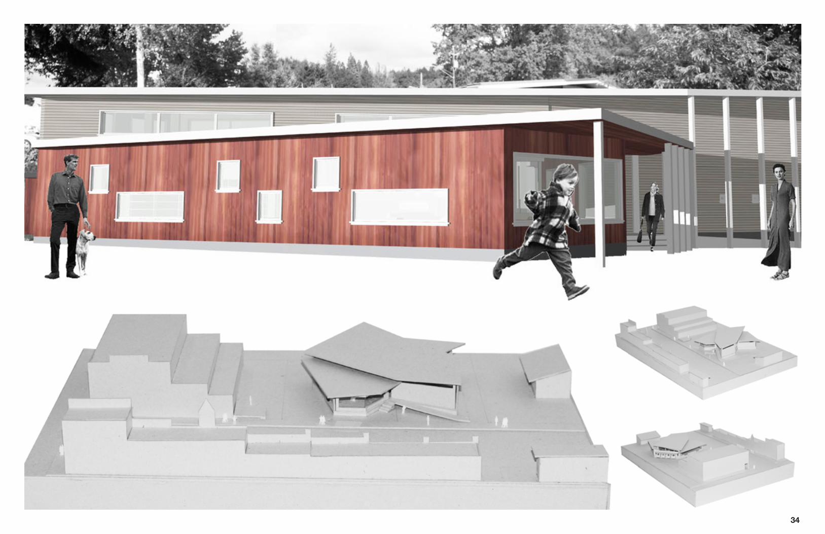
Framed GardensBrownsville Public Library
Brownsville, OR Arch 284 • Kristen Distefano Studio • Fall 2008
Media: Archicad, Photoshop, Illustrator, Physical Models
Brownsville, Oregon Overview: Brownsville is a small town located in the Southern Willamette Valley. �e town was founded in the 1840’s and is currently home to a population of 1,700.
Concept Statement: Brownsville is a town with a rich landscape and an intimate community. �ese characteristics o�er many possibilities for a public library to prosper and create a cen-tral node for the community. �e site and its commercial context is enveloped by a beautiful hillside with a dense variety of tree species. A place with such a beautiful natural setting should take advantage of the views it provides. �e Brownsville public library emcompasses the connections between the community and its landscape. �e building frames views to its outdoor gardens as well as the dense hillside to provide scenic and meditative spaces. �e building provides private/public places to read, a computer room, a childrens play area and a public conference room. �is library provides a multi-use building for the community.
31
PARTIParti
Conceptual Models
FRAMED VIEWS
Reading Room Views

32
Roof Study
�e goal was to design a roof that would maximize the daylight in the book stacks area while minimizing lighting in the other spaces.

R
DN
DN
DN
Floor Plan
View of the Reception Desk
View of the Reading Room
View of the Stacks and Reading Nook
1. Entry 5. Information Desk 9. Deck 2. Reading Room 6. Meeting Room 10. Bathrooms3. Reading Nooks 7. Computer Room 11. Kitchenette4. Book Stacks 8. Kids Room 12. Rear Entrance
1
2
3 4
5
6
3
3
3
7
8
9
10
10
11
12
33
34