Embed Size (px)
Citation preview

3
POS-E-KONTM
Pos-E-Kon™
Table of Contents
A 10A 3/4, 10, 16, 32 16, 17
B 16A 6, 10, 16, 24, 32, 48 18-21
C 35A 6, 12 22, 23
D 10A 7/8, 15, 25, 40, 50, 64, 80, 128 24-27
DD 10A 24, 42, 72, 108, 144, 216 28-31
K 16A/80A 8 + 4, 16 + 8 32, 33
V 16A 3, 6, 10, 16, 20, 26, 32 (all +2) 34-37
T 16A/200°C 6, 10, 16, 24 (200°C) 38, 39
M Spec Modular 40-50
FAQs. . . . . . . . . . . . . . . . . . . . . . . . . . . . . . . . . . . . . . . . . . . . . . . . . . . . . . . . . . . . . . . . . . . . . . . . . . . . . . . . . . . 4The System . . . . . . . . . . . . . . . . . . . . . . . . . . . . . . . . . . . . . . . . . . . . . . . . . . . . . . . . . . . . . . . . . . . . . . . . . . . . . 5Insert Selector Chart . . . . . . . . . . . . . . . . . . . . . . . . . . . . . . . . . . . . . . . . . . . . . . . . . . . . . . . . . . . . . . . . . . . . 6, 7Hood and Base Housings . . . . . . . . . . . . . . . . . . . . . . . . . . . . . . . . . . . . . . . . . . . . . . . . . . . . . . . . . . . . . . . . . . 8Using the Catalogue. . . . . . . . . . . . . . . . . . . . . . . . . . . . . . . . . . . . . . . . . . . . . . . . . . . . . . . . . . . . . . . . . . . . . . . 9Accessories. . . . . . . . . . . . . . . . . . . . . . . . . . . . . . . . . . . . . . . . . . . . . . . . . . . . . . . . . . . . . . . . . . . . . . . . . . 10-13Catalogue Numbering System . . . . . . . . . . . . . . . . . . . . . . . . . . . . . . . . . . . . . . . . . . . . . . . . . . . . . . . . . . . . . . 14Series Locator . . . . . . . . . . . . . . . . . . . . . . . . . . . . . . . . . . . . . . . . . . . . . . . . . . . . . . . . . . . . . . . . . . . . . . . . . . 15Reference and Accessories . . . . . . . . . . . . . . . . . . . . . . . . . . . . . . . . . . . . . . . . . . . . . . . . . . . . . . . . . . . . . . . . 51Fiber Optic Connections . . . . . . . . . . . . . . . . . . . . . . . . . . . . . . . . . . . . . . . . . . . . . . . . . . . . . . . . . . . . . . . . . . 72
Series Amperage Contacts + G Page@ 600VAC
1-5.pdf 3 1/5/2012 2:45:05 PM1-76.pdf 3 1/6/2012 10:52:54 AM

Pos-E-Kon™
Frequently Asked Questions
4
Answers to the Ques tions Most Frequently Askedby Users of Pos-E-Kon Connectors
International Standards, World wide Use
How?
Why?
Rectangular Circuit In ter con nec tions• Best use of space for multiple con tacts in heavy
duty housings.• Easy to assemble with many different insert
options. • Best fit for easy access in panels, machinery,
and en clo sures.• Sealed connector with quick disconnect han-
dles.• Wide variety of circuit pos si bil i ties from stan-
dard items.• Solid or stranded wire in fixed or portable
applications.
Who? • Machine tool OEMs.• Material handling equipment OEMs.• Ro bot ics systems OEMs and installations.• Packaging ma chin ery OEMs and facilities.• Control panels and PLC systems.• Mold ing, assembly, or line machinery OEMs
and facilities.• Con struc tion, mining, and weld ing apparatus.• Carnival applications.
What? • Servo controls.• Sensing and feedback loops.• Conveyor and process controls.• Low power, DC, or logic systems.• Com bi na tion power systems and other circuits.• Mod u lar controls in clud ing fiber-optics connections.
Where? Worldwide agency approvals and applications• DIN VDE 0627/86, 0110/02.79, and 0110-1/04.97.• IEC 60.664-1, DIN/IEC 512.• UL recognized (E215386) and CSA certified • Pro tec tion classes IP44 through IP65 per IEC 529.• Component use in CE marked equipment OK per
IEC Council Directive July 1999, 73/23/EEC.
• Available from Thomas & Betts–Pos-E-Kon authorized distributors.• For sales and service, contact your Thomas & Betts Regional Sales Office. Refer to back cover
for contact information.
1-5.pdf 4 1/5/2012 2:45:05 PM1-76.pdf 4 1/6/2012 10:52:54 AM

5
Pos-E-Kon™
The System
POS-E-KONTM
As Easy As 1. 2. 3. 4.
1. Hood• Separable housing for inserts.• Top or side conduit/wire entry.• Standard locking posts, dual or single.• Locks to Panel Base, Box Base or in-line
Coupler Hood
2. Base Housing (or Coupler Hood)• Surface wall mount box base (shown).• Panel Base for through-panel access.• Coupler Hood mating for portable use.• Single or dual “Lever” locking.
3. Male Insert• Male contact carrier body.• Screw terminal contacts (pins with wire
protection saddles) or crimp terminatedpins.
4. Female Insert• Female contact carrier.• Screw terminal contacts (sleeves with
wire protection saddles) or crimp terminated sleeves.
The Basic System: How to Build for an ApplicationStep 1 —Maximum voltage and amperage requirements (300V or 600V classes, 10-80 amps).Step 2 —Number of contacts or circuits needed.Step 3 —Choose wire termination style; screw terminal or crimp contacts. Select series from charts.Step 4 —Base (or Coupler) and Hood construction/mating selection per series (single or double levers).
HOOD
BASE (OR COUPLER HOOD)
MALE INSERT
FEMALEIN SERT
CABLE ENTRYWITH FITTING
CABLE ENTRY WITH FITTING
DIN Standard Configurations
• Most inserts and housings are interface compatible with other DIN standard lines.
• Pos-E-Kon construction includes standard NPT conduit adapters for hoods and bases, with manyoptions available. DIN standard hoods and bases may have “Euro Style” Pg fittings (or none) included unless specially ordered.
1-5.pdf 5 1/5/2012 2:45:05 PM1-76.pdf 5 1/6/2012 10:52:54 AM

Pos-E-Kon™
Pos-E-Kon Insert Selector Chart
6
S — Screw TerminalsC — Crimp ContactsF — Fiber Optic (POF)A — Terminal Block Wiring Adapter
Screw Terminal / Insert Types (Integral Contacts)
10 - 16A A, B, V, T
35A C
16 - 80A K
16AA & B
10AD & DD
POFD & M
Signal 1.5 AM-Coax
50 AmpM3
16 AmpM 4/5
20 AmpM5
5 AmpM20
Crimp Terminal / Insert Types (Crimp Contacts)
• All crimp types represented require contacts ordered separately.• Each section contains hand crimp tool selection notes.
Thermocouple compensated contacts (crimp) also available (Fe and Cu) for A & B series inserts.Contact your Thomas & Betts Regional Sales Office. See back cover for contact information.
10AD & DD
16A A & B
5-50A M
Screw termination is used for ease of assembly, some heavier gauge wires plusease of maintenance. No tooling beyond a screwdriver and wire strippers isrequired.
Crimp terminals offer solid, thermally cool, vibration resistant terminations for OEMequipment and critical applications. Better for smaller AWG sizes also. Crimp toolsare noted in each section.
NEW
Select the number of contacts – All inserts have separate ground contacts
AMPS VOLTS Series 3 4 6 7 8 10 12 15 16 20 24 25 26 32 40 42 48 50-216
10 50 D C, F
10 600 A S S
16 600 A S, C S, C S, C
16 600 B S, C, A S, C, A S, C, A S, C, A S, C S, C
35 600 C S S
10 600 D C, F C, F C, F C, F, A C, F, A (64)
10 600 DD C, F C, F C, F
80/16 600 K S S Combination Inserts: 4 power (80A) + 8 control (16A), 8 power (80A) + 16 control (16A).
16-T 600 T S S S S High Temp (200°C)
16-V 600 V S, C S, C S, C S, C S, C S, C S, C Includes 2 Pilot Contacts
Modular 600 M Configure to individual specs. Options: Fiber Optic, Power and Control Pin selections in sectional inserts. Contact Tech Service for Information.
6-20.pdf 1 1/5/2012 2:45:30 PM1-76.pdf 6 1/6/2012 10:52:54 AM

7
Pos-E-Kon™
Insert Selection
POS-E-KONTM
• Integral screw terminal contacts provide for easy terminal wiring, fast assembly.
• Standard wire protection saddles prevent cutting of strands during assembly.
• Provides reliable connections for long-termconfigurations.
• Contact sizes accommodate wiring from 12 - 20 AWG.
• Made of durable glass fiber-filled thermoplastic. • Contact numbers clearly marked for easy identification.• Easily installed (male or female) in either hoods or bases using captive mounting screws.
WAR, Right Ground StrapWAL, Left Ground Strap
• Allow for measuring of circuit while in operation.• Provide easy connections in panel mounting configurations.• Labels available for easy identification of circuits.• Can be mounted on DIN rails by using snap-on mount feet.• Used in switch cabinets, panel enclosures or mounted in panel
base housings – see B and D series.
WAM1 – Insert Strip Blank – WAM1BInsert Strip Nos. 1-64 – WAM1N64Insert Strip Letters A-Z – WAM1AZ
WAM2 – Insert Strip Blank – WAM2BInsert Strip Nos. 1-64 – WAM2N64Insert Strip Letters A-Z – WAM2AZ
WAM1 Marker Tab ClipsSnap-in formed label holder tabs allow terminalidentification for B Series.
WAM2 Marker Tab ClipsSnap-in formed label holder tabs allow terminalidentification for D Series.
Terminal Block Wiring Adapters
DIN Mounting Foot FE807TB
Screw Terminal Inserts Crimp Terminal Inserts
6-20.pdf 2 1/5/2012 2:45:30 PM1-76.pdf 7 1/6/2012 10:52:54 AM
Pos-E-Kon™
Hood and Base Housings
8
• Rugged cast aluminum hoods and bases: Maximum performance in many operating conditions.
• Various hood heights available: Easier assembly and wiring with low, high and standard profiles.
• Corrosion resistant finishes: Optional special materials extend life in corrosive conditions.
• Locking possibilities include single locking system and double locking system.
• Complete selection: Flexible product designs (see Hood/Base Size Cross Reference Chart below).
• Dust Covers and More: See Adapters, pp. 9-10 and Covers p. 10 (or Bases w/Covers) available inmost series (Accessories p. 66 ) see pp. 67-68 for all Adapter Plates.
• Custom Configurations: Multiple conduit entry/sizes and other configurations available to spec.
Cross Reference
Applications Standard Hood/Base Housings
AMPS VOLTS Series A4 A10 A16 A32 B6 B10 B16 B24 B32 B48
10A 50 D D8
10A 600 A A3, A4
16A 600 A A10 A16 A32
16A 600 B B6 B10 B16 B24 B32 B48
35A 600 C C6 C12
10A 600 D D7 D15 D25 D50 D40 D64 D80 D128
10A 600 DD DD24 DD42 DD72 DD108 DD144 DD216
80/16A 600 K K4/8 K8/16
ModularM 600 M M, B6 M, B10 M, B16 M, B24 M, B16 M, B24
16A-Tn 600 T T6 T10 T16 T24
16A-V* 600 V V3 V6 V10 V32
* Special isolation design allows additional control circuit capability.n Special high temperature series in Cu-Free Aluminum with special green epoxy powder-coat, Viton® seals.†
† Viton is a trademark of DuPont Dow Elastomers.
Applications Special Series Hood/Base Housings
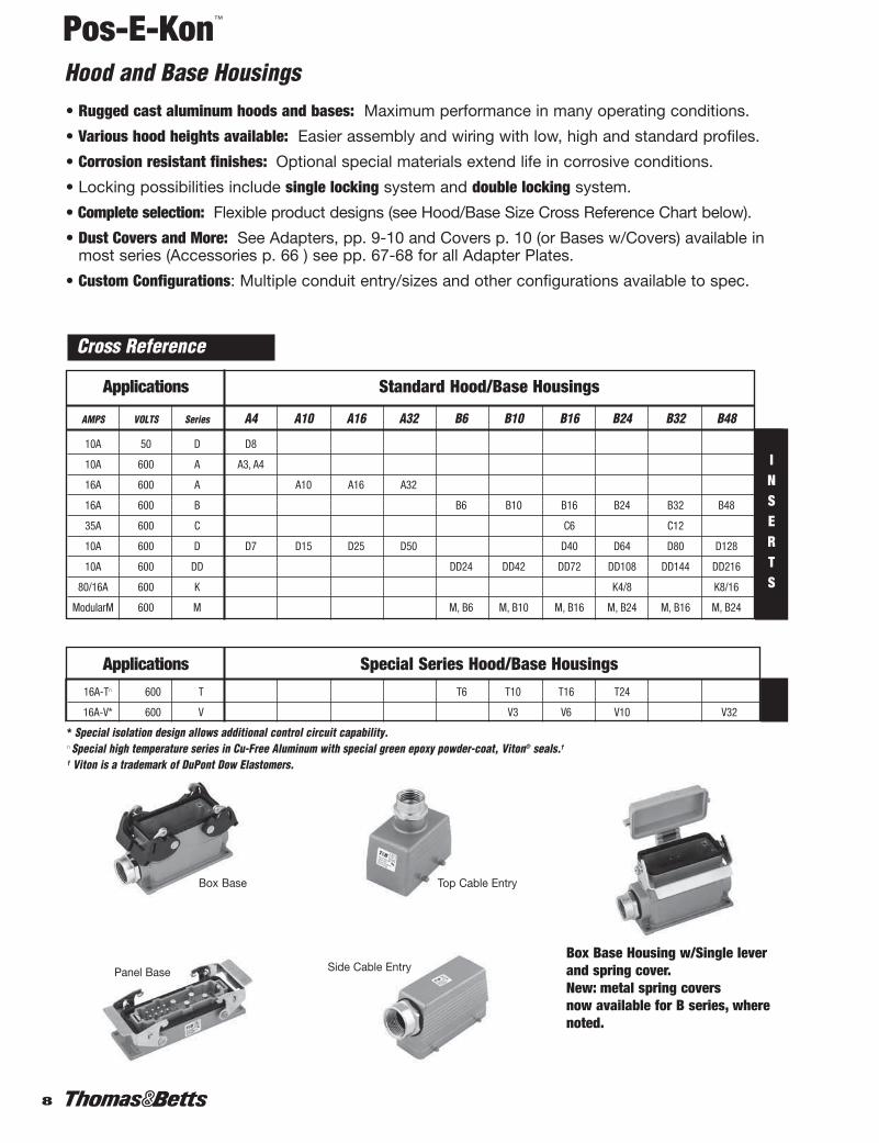
Box Base Housing w/Single leverand spring cover. New: metal spring covers now available for B series, wherenoted.
INSERTS
Panel Base Side Cable Entry
Box Base Top Cable Entry
6-20.pdf 3 1/5/2012 2:45:30 PM1-76.pdf 8 1/6/2012 10:52:54 AM

9
Pos-E-Kon™
Using the Catalogue: Series layout
POS-E-KONTM
STANDARDBASES
STANDARDHOODS
Portable Service
COUPLER HOODS
Reverse Locking
LEVER HOODS
POST BASES
1. For each series, select size (number of contacts) from the chart on the left hand page (selectedinserts), then look at corresponding right hand page columns.
2. Vertical columns note single or double locking systems available (double locking usually preferable).
3. Select base housings for mounting and/or function: conduit/cable entry, through-panel access, in-line coupler or reversed locking as shown (note profile height options).
4. Select side or top entry hoods as shown (note profile height options).
5. Review conduit and cable entry options (standard NPT adapter sizes for each series).
Note: M Series (layout) groups interior options, followed by base selection options.
Each Right Hand Page Shows:
HOODTO
BASE
HOODTO
BASE
HOODTO
COUPLER
6-20.pdf 4 1/5/2012 2:45:31 PM1-76.pdf 9 1/6/2012 10:52:54 AM
Pos-E-Kon™
Accessories
10
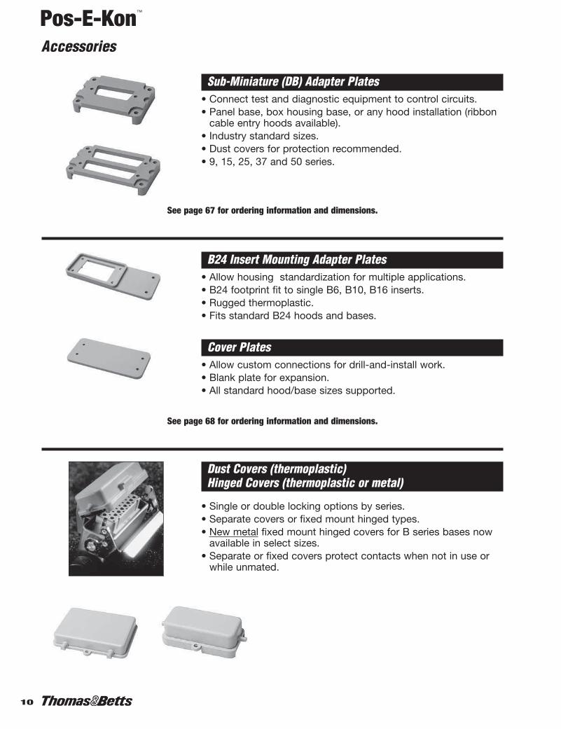
Sub-Miniature (DB) Adapter Plates• Connect test and diagnostic equipment to control circuits.• Panel base, box housing base, or any hood installation (ribbon
cable entry hoods available).• Industry standard sizes.• Dust covers for protection recommended.• 9, 15, 25, 37 and 50 series.
B24 Insert Mounting Adapter Plates• Allow housing standardization for multiple applications.• B24 footprint fit to single B6, B10, B16 inserts.• Rugged thermoplastic.• Fits standard B24 hoods and bases.
Cover Plates• Allow custom connections for drill-and-install work.• Blank plate for expansion.• All standard hood/base sizes supported.
See page 67 for ordering information and dimensions.
See page 68 for ordering information and dimensions.
• Single or double locking options by series.• Separate covers or fixed mount hinged types.• New metal fixed mount hinged covers for B series bases now
available in select sizes.• Separate or fixed covers protect contacts when not in use or
while unmated.
Dust Covers (thermoplastic) Hinged Covers (thermoplastic or metal)
6-20.pdf 5 1/5/2012 2:45:32 PM1-76.pdf 10 1/6/2012 10:52:55 AM
11
Pos-E-Kon™
Accessories
POS-E-KONTM
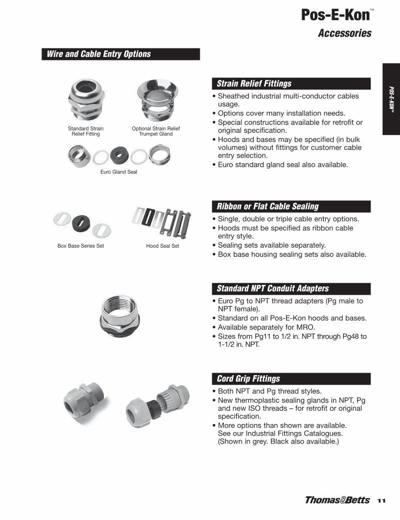
Cord Grip Fittings• Both NPT and Pg thread styles.• New thermoplastic sealing glands in NPT, Pg
and new ISO threads – for retrofit or original specification.
• More options than shown are available. See our Industrial Fittings Catalogues. (Shown in grey. Black also available.)
Ribbon or Flat Cable Sealing• Single, double or triple cable entry options.• Hoods must be specified as ribbon cable
entry style.• Sealing sets available separately.• Box base housing sealing sets also available.
Hood Seal SetBox Base Series Set
Wire and Cable Entry Options
Strain Relief Fittings• Sheathed industrial multi-conductor cables
usage.• Options cover many installation needs.• Special constructions available for retrofit or
original specification.• Hoods and bases may be specified (in bulk
volumes) without fittings for customer cable entry selection.
• Euro standard gland seal also available.
Standard Strain Relief Fitting
Euro Gland Seal
Optional Strain ReliefTrumpet Gland
Standard NPT Conduit Adapters• Euro Pg to NPT thread adapters (Pg male to
NPT female).• Standard on all Pos-E-Kon hoods and bases.• Available separately for MRO.• Sizes from Pg11 to 1/2 in. NPT through Pg48 to
1-1/2 in. NPT.
6-20.pdf 6 1/5/2012 2:45:32 PM1-76.pdf 11 1/6/2012 10:52:55 AM
Pos-E-Kon™
Accessories
12
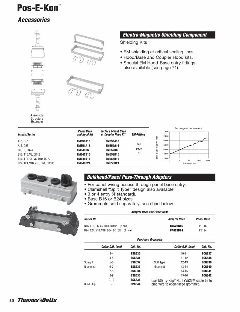
Electro-Magnetic Shielding Component Shielding Kits
• EM shielding at critical sealing lines.• Hood/Base and Coupler Hood kits.• Special EM Hood-Base entry fittings
also available (see page 71).
Rectangular connectors
Shie
ld a
bsor
ptio
n (d
B)
Frequency F (MHz)
Panel Base Surface Mount BaseInserts/Series and Hood Kit or Coupler Hood Kit EM-Fitting
A10, D15 EM650A10 EM656A10A16, D25 EM651A16 EM657A16B6, T6, DD24 EM646B6 EM652B6B10, T10, V3, DD42 EM647B10 EM653B10B16, T16, C6, V6, D40, DD72 EM648B16 EM654B16B24, T24, V10, V16, D64, DD108 EM649B24 EM655B24
Bulkhead/Panel Pass-Through Adapters• For panel wiring access through panel base entry.• Clamshell “Split Type” design also available.• 3 or 4 entry (4 standard).• Base B16 or B24 sizes.• Grommets sold separately, see chart below.
Adapter Hood and Panel Base
Series No. Adapter Hood Panel Base
B16, T16, C6, V6, D40, DD72 (3 hole) CA628B16 PB116B24, T24, V10, V16, D64, DD108 (4 hole) CA629B24 PB124
Feed-thru Grommets
Cable O.D. (mm) Cat. No. Cable O.D. (mm) Cat. No.
3-4 BSG630 10-11 BCG6374-5 BSG631 11-12 BCG638
Straight 5-6 BSG632 Split Type 12-13 BCG639Grommet 6-7 BSG633 Grommet 13-14 BCG640
7-8 BSG634 14-15 BCG6418-9 BSG635 15-16 BCG6429-10 BSG636
Blind Plug – BPG644
AssemblyStructureExample
seepage71
Use T&B Ty-Rap® No. TYV523M cable tie tobind wire to open-faced grommet.
6-20.pdf 7 1/5/2012 2:45:33 PM1-76.pdf 12 1/6/2012 10:52:55 AM

13
Pos-E-Kon™
Accessories
POS-E-KONTM
Improvements for 2001Introducing: New Ergonomic thermoplastic levers for “B” series double lever housings B10-B24
Benefits: Non-slip comfortable gripEasier locking and unlocking
And: New Laser etched labeling for all metal housings and hot-stamped labeling on contact carrier inserts.
Benefits: Permanent marking with all data combinedExternal marking vs. internal label
Metallic levers will continue to be available for all double lever housings.
(Minimum order requirements)
New “E” type levers will be standard for double lever B10through B24 size housings. All single lever housings are
constructed with metallic levers.
Reference: Catalogue Number Conversion• Add “E” suffix for Ergonomic style levers for all B10, 16 and 24 double-lever housings.
Example: PB116 (Metal levers) becomes PB116E (Thermoplastic levers)LH224 (Metal levers) becomes LH224E (Thermoplastic levers)
Catalogue Numbers affected (New catalogue number construction shown in catalogue)
B10 Series B16 Series B24 Series
PB110 PB116 LH016 PB124 CH624BB010 BB016 LH016H BB024 CH724BB110 BB116 LH116H BB124 LH124BB610 BB616 LH216 LH224BB710 BB716 LH216H LH024CH810 CH616 LH324
6-20.pdf 8 1/5/2012 2:45:33 PM1-76.pdf 13 1/6/2012 10:52:55 AM

Pos-E-Kon™
Catalogue Number System
14
Double posts (front/back) forDouble Lever locking.(single side post/lever also)
HoodsTH – Top Entry Hood w/NPT fittingSH – Side Entry Hood w/NPT fitting
Male and Female Inserts-same installation to anyhood or base orientation
MS – Male Screw Terminal Insert (shown)
FS – Female Screw TerminalInsert (shown)– OR –
MC – Male Crimp InsertFC – Female Crimp Insert >use MP –Male and FP –FemalePins
Base TypesBB – Box Base Housing
Surface Mount with NPTconduit Entry (1 or 2) fit-tings (standard)
Locking • Single lever/Single post or Double lever/Double posts locking.• “Reversed Locking” (levers on hoods) available.• New E-series ergonomic thermoplastic handles for double lever B series (B10, B16, B24).• Single lever & other series use metal levers.
PB – Panel Base HousingPanel face or bulkhead mountingwith rear wiring access
CH – Coupler HoodInline PortableConnection
Easy to use—Catalogue number construction pioneered by Thomas & Betts
Wiring Entry optionsCord or Conduit Adapter fittingsRibbon cable & Euro cable entry Housings without fittingsCustom assemblies
Male and FemaleTerminal Block Wiring AdaptersMS or FSxxxWAR/WAL(right/left ground) optionsfor Panel Base installations.
6-20.pdf 9 1/5/2012 2:45:34 PM1-76.pdf 14 1/6/2012 10:52:55 AM

15
Pos-E-Kon™
Series Locator
POS-E-KONTM
A Series: Small, Compact Size 3, 4, 10, 16, 32 16Screw Terminal or Crimp Contacts
B Series: Standard Size 6, 10, 16, 24, 32, 48 18Screw Terminal or Crimp Contacts
C Series: High Current 6 or 12 22Screw Terminal
D Series: Hi-Density 7, 8, 15, 25, 40, 24Crimp Contacts or 50, 64, 80, 128Fiber Optic Contacts
DD Series: Very Hi-Density 24, 42, 72, 108, 144, 216 28Crimp Contacts orFiber Optic Contacts
K Series: Combo, 16A: 8 + 4 32Hi-Current/Std. Current 80A: 16 + 8Screw Terminals
V Series: Control Circuit 3, 6, 10, 16, ) +2 34Contacts and B Style 20, 26, 32 Screw Terminals
T Series: B Style 6, 10, 16, 24 38Hi-Temp 200°CScrew Terminals
M Series: All Modular Several to 50A 40Crimp Contacts and 3, 5, 7 Piece Fiber Optic Contacts Insert holders
Reference & Specs, Dimensions, 51Accessories Components and
Fiber Optics
10A: 3, 416A: All other
16A
35A
10A
10A
16A
16A
(Various)
16A/80A
Series Features Contacts + G Page
6-20.pdf 10 1/5/2012 2:45:36 PM1-76.pdf 15 1/6/2012 10:52:55 AM

Pos-E-Kon™
A Series 10 and 16 Amps 600 VAC
16
Crimp Tool Contacts Selection
Crimp Terminal Inserts 10 + G 16 + G 32 + G
Male InsertMC410A MC416A
MC416A
(Order contacts below) MC432A
Female InsertFC310A FC316A
FC316A(Order contacts below) FC332A
Crimp Contacts Wire AWG (mm2) Identification
20 AWG (0.5 mm2) No Groove
18 AWG (0.75-1 mm2) 1 Groove
16 AWG (1.5 mm2) 2 Grooves
14 AWG (2.5 mm2) 3 Grooves
12 AWG (4.0 mm2) No Groove
3 or 4 Contacts + Ground: 10A10, 16 & 32 Contacts + Ground: 16A
Install toMatching Series
Hood/Base
WT611TB
DIN Rail Adapter Mount Frames 10 + G 16 + G
150mm long, with base for AMF115 AMF125snapping onto DIN rail
Adapter Mount Frames allow “open”wiring inside closed panel enclosure.They also allow Inserts to be assem-bled as a separable Terminal Blockdevice.
3 or 4 (600V) 10 16 32
For all Inserts
Screw Terminal Inserts 3 or 4 + G 10 + G 16 + G 32 + G
Male – Pins MS203A or MS216A
20-14 AWG (0.5-2.5 mm2)MS204A MS210A MS216A +
(16 AWG max) MS232A
Female – Sleeves FS103A or FS116A
20-14 AWG (0.5-2.5 mm2)FS104A FS110A FS116A +
(16 AWG max) FS132A
Female Male
FP2000 MP2000
FP1800 MP1800
FP1600 MP1600
FP1400 MP1400
FP1200 MP1200
For all Crimp Terminal “A” Inserts
Use small blade screwdriverto push in wire entry tab foreasy contact removal.
Groove
+
+
6-20.pdf 11 1/5/2012 2:45:36 PM1-76.pdf 16 1/6/2012 10:52:55 AM

17
Pos-E-Kon™
A Series 10 and 16 Amps 600 VAC
POS-E-KONTM
Top Entry
Box Base (no Cover)
Lever Locking TypeHousing
Hoods – Standard Mount
1 X 3/8" SH603A(P)s1 X 1/2" SH610A* SH616A*1 X 3/4" SH710A** SH716A** SH032A1 X 1" SH132A
1 X 3/8" TH803A(P)s1 X 1/2" TH810A* TH816A*1 X 3/4" TH910A** TH916A** TH232A1 X 1" TH332A
Side Entry
Plastic body – “A” 3-16 Series standard Hoods include Gaskets: Bases and Special Hoods do not.
Top Entry
LH032ALH132A
LH232ALH332A
PB232A
BB232ABB232A100
BB332ABB332A100
3 or 4 (600V) 10 16 32
Lever Hoods mate to Post Bases ONLY.
Number of Contacts + Ground Connection
BASE
TO
HOOD
HOOD
TO
COUPLER
COUPLER
HOOD
TO
BASE
HOODS
HOODS
BASES
BASE
Post Bases accept Lever Hoods ONLY.Bases – with Access Cover
Panel Base+Posts w/Cover
1 X 3/4"Box Base+ 1 X 1"
Posts w/Cover 2 X 3/4"2 X 1"
Lever Hoods – Rev. Lock
Side Entry 1 X 3/4"w/Lever(s) 1 X 1"
Top Entry 1 X 3/4"w/Lever(s) 1 X 1"
For In-line, Portable or Special Service ConnectionsCoupler Hoods – In-line
1 X 3/8" CH803A(P)s1 X 1/2" CH810A CH816A
Single Lever Double Lever
*Available in Standard or LOW Profile “L” configurations (add suffix L).s (P) indicates glass-filled thermoplastic construction, light grey colour (add suffix P).
(PB) indicates glass filled thermoplastic construction, black colour (add suffix PB). Minimum quantity. Purchase may be required.
Reverse Locking
NPTBases – Standard Mount Entry Single Single Single Double
Panel Base PB303A(P)s PB310A PB316A PB132A
w/Cover PB403A PB410A PB416A
Angled PB503A(P)sno Cover
1 X 3/8" BB403A(P)s1 X 1/2" BB410A BB416A1 X 3/4" BB032A1 X 1" BB832A2 X 1/2" BB510A BB516A2 X 3/4" BB132A2 X 1" BB132A100
Box Base 1 X 1/2" BB610A BB616Aw/Cover 2 X 1/2 BB710A BB716A
Coupler Hoods mate to Standard Hoods ONLY.
17-E.pdf 1 2/2/2012 10:08:21 AM

Pos-E-Kon™
B Series 16 Amps 600 VAC
18
Crimp Tool
Crimp Terminal Inserts 6 + G 10 + G 16 + G
Male Insert MC406B MC410B MC416B(Order contacts below)
Female Insert FC306B FC310B FC316B(Order contacts below)
For all Crimp Terminal “B” Inserts
Screw Terminal Inserts 6 + G 10 + G 16 + G
Male – PinsMS206B MS210B MS216B
20-14 AWG (0.5-2.5 mm2)
Female – SleevesFS106B FS110B FS116B
20-14 AWG (0.5-2.5 mm2)
Crimp Contacts Wire AWG (mm2) Identification Female Male
20 AWG (0.5 mm2) No Groove FP2000 MP2000
18 AWG (0.75-1 mm2) 1 Groove FP1800 MP1800
16 AWG (1.5 mm2) 2 Grooves FP1600 MP1600
14 AWG (2.5 mm2) 3 Grooves FP1400 MP1400
12 AWG (4.0 mm2) No Groove FP1200 MP1200
DIN Rail Adapter Mount Frames 6 + G 10 + G 16 + G
125 mm long, with baseAMF006 AMF010 AMF016
for snapping onto DIN rail
150 mm long, with baseAMF106 AMF110 AMF116
for snapping onto DIN rail
150 mm long, with baseAMF112 – –
for TWO inserts
6, 10, 16, 24, 32, 48 Contacts + Ground
Install toMatching Series
Hood/Base
6 10 16 6 10 16 6 10 16
Adapter Mount Frames allow “open” wiringinside closed panel enclosure. They alsoallow Inserts to be assembled as a separableTerminal Block device.
Accepts any Terminal Insert to same series.
Screw Terminal Wiring Adapter Blocks 6 + G 10 + G 16 + G
Male Insert, Ground L.MS206WAL MS210WAL MS216WAL
20-14 AWG (0.5-2.5 mm2)
Male Insert, Ground R.MS206WAR MS210WAR MS216WAR
20-14 AWG (0.5-2.5 mm2)
Female Insert, Ground L.FS106WAL FS110WAL FS116WAL
20-14 AWG (0.5-2.5 mm2)
Female Insert, Ground R.FS106WAR FS110WAR FS116WAR
20-14 AWG (0.5-2.5 mm2)
Foot Element mounting FE807TB FE807TB FE807TBadapter for DIN rail 2 needed 2 needed 2 needed
Contacts Selection
Accessories Catalogue No.
Label Insert Clip WAM-1Strip blank WAM1B
Strip Nos. 1-64 WAM1N64Strip Letters A - Z WAM1AZ
Wiring Adapter Insert for use with PanelBases; allows single access direction
panel-build wiring and easy terminal ID for service and testing.
For all Inserts
WT611TB
Use small blade screwdriver to push inwire entry tab for easy contact removal.
Groove
6-20.pdf 13 1/5/2012 2:45:39 PM1-76.pdf 18 1/6/2012 10:52:55 AM

19
Pos-E-Kon™
B Series 16 Amps 600 VAC
POS-E-KONTM
Lever Locking Type
For In-line, Portable or Special Service Connections
LH010ELH010EH075 LH016E*LH010EH100 LH116EH
LH210ELH210EH075 LH216E*LH210EH100 LH316EH
PB210 n PB216 n
BB210 n
BB210H075 n BB216* n
BB210H100 n BB216H100 n
BB310 n
BB310H075 n BB316* n
BB310H100 n BB316H100 n
Post Bases accept Lever Hoods ONLY.
BASE B
ASE
TO
HOOD
HOOD
TO
COUPLER
COUPLER
Box Base( no Cover )
Side Entry
Top Entry
Top Entry
Side Entryw/Lever(s)
Top Entryw/Lever(s)
Box + Postsw/Cover
Box Basew/Cover
*Available in Standard or HIGH Profile “H” configurations (add suffix H).n Add “M” final suffix for metal cover option.u Both HIGH (H) and LOW (L) profile also available (add suffix H or L).
Lever Hoods mate to Post Bases ONLY.
HOOD
TO
BASE
HOODS
HOODS
BASES
6 10 16 Number of Contacts + Ground Connection
Bases – with Access Cover
Panel + Postsw/Cover
1 X 1/2"1 X 3/4"1 X 1"2 X 1/2"2 X 3/4"2 X 1"
Lever Hoods – Reversed Lock1 X 1/2"1 X 3/4"1 X 1"
1 X 1/2"1 X 3/4"1 X 1"
Single Lever Double Lever NPTBases – Standard Mount Entry Single Single Double Single Double
Panel Base PB306 n PB310 n PB110E PB316 n PB116E
w/Cover PB406 n PB410 n PB416 n
1 X 1/2" BB406 BB410 BB010E1 X 3/4" BB406H075 BB410H075 BB010EH075 BB416* BB016E*1 X 1" BB406H100 BB410H100 BB010EH100 BB416H100 BB016EH1002 X 1/2" BB506 BB510 BB110E2 X 3/4" BB506H075 BB510H075 BB110EH075 BB516* BB116E*2 X 1" BB506H100 BB510H100 BB110EH100 BB516H100 BB116EH100
1 X 1/2" BB606 n BB610 n
1 X 3/4" BB606H075 n BB610H075 n BB616* n
1 X 1" BB606H100 n BB610H100 n BB616H100 n
2 X 1/2" BB706 n BB710 n
2 X 3/4" BB706H075 n BB710H075 n BB716* n
2 X 1" BB706H100 n BB710H100 n BB716H100 n
Hoods – Standard Mount1 X 1/2" SH606 SH610 SH0101 X 3/4" SH606H075 SH610H075 SH010H075 SH616u SH016u1 X 1" SH606H100 SH610H100 SH010H100 SH716u SH116Hu
1 X 1/2" TH806 TH810 TH2101 X 3/4" TH806H075 TH810H075 TH210H075 TH816u TH216u1 X 1" TH806H100 TH810H100 TH210H100 TH816H100 TH316H
Coupler Hoods – In-line Coupler Hoods mate to Standard Hoods ONLY.
1 X 1/2" CH806 CH810 CH610E1 X 3/4" CH806H075 CH810H075 CH610EH075 CH816H CH616EH1 X 1" CH806H100 CH810H100 CH610EH100 CH916H CH716EH
Reverse Locking
Housing
6-20.pdf 14 1/5/2012 2:45:39 PM1-76.pdf 19 1/6/2012 10:52:55 AM

Pos-E-Kon™
B Series 16 Amps 600 VAC
20
Crimp Tool Contacts SelectionCrimp Contacts Wire Gauge AWG (mm2) Identification Female Male
20 AWG (0.5 mm2) No Groove FP2000 MP2000
18 AWG (0.75-1 mm2) 1 Groove FP1800 MP1800
16 AWG (1.5 mm2) 2 Grooves FP1600 MP1600
14 AWG (2.5 mm2) 3 Grooves FP1400 MP1400
12 AWG (4.0 mm2) No Groove FP1200 MP1200
Install toMatching Series
Hood/Base
Adapter Mount Frames allow “open”wiring inside closed panel enclosure. They also allow Inserts to be assembledas a separable Terminal Block device.
For all Crimp Terminal “B” Inserts
DIN Rail Adapter Mount Frames 24 + G
150 mm long, with baseAMF124
for snapping onto 33 mm rail
Accessories Catalogue No.
Label Insert Clip WAM-1Strip blank WAM1B
Strip Nos. 1-64 WAM1N64Strip Letters A - Z WAM1AZ
Wiring Adapter Insert for use with PanelBases; allows single access direction
panel-build wiring and easy terminal IDfor service and testing.
24 32 48 6, 10, 16, 24, 32, 48 Contacts + Ground
Screw Terminal Inserts 24 + G 32 + G 48 + G
Male PinsMS224B
MS216B (1-16) MS224B (1-24)
20-14 AWG (0.5-2.5 mm2) MS232B (17-32) MS248B (25-48)
Female SleevesFS124B
FS116B (1-16) FS124B (1-24)
20-14 AWG (0.5-2.5 mm2) FS132B (17-32) FS148B (25-48)
Screw Terminal Wiring Adapter Blocks 24 + G
Male Insert, Ground L.MS224WAL
20-14 AWG (0.5-2.5 mm2)
Male Insert, Ground R.MS224WAR
20-14 AWG (0.5-2.5 mm2)
Female Insert, Ground L.FS124WAL
20-14 AWG (0.5-2.5 mm2)
Female Insert, Ground R.FS124WAR
20-14 AWG (0.5-2.5 mm2)
Foot Element mountingFE807TB
adapter for DIN rail
Crimp Terminal Inserts 24 + G 32 + G 48 + G
Male InsertMC424B
(1-16) MC416B (1-24) MC424B(Order contacts below) (17-32) MC432B (25-48) MC448B
Female InsertFC324B
(1-16) FC316B (1-24) FC324B(Order contacts below) (17-32) FC332B (25-48) FC348B
For all Inserts
WT611TB
Use small blade screwdriver to push wirein entry tab for easy contact removal.
Groove
+ +
+ +
6-20.pdf 15 1/5/2012 2:45:40 PM1-76.pdf 20 1/6/2012 10:52:55 AM

21
Pos-E-Kon™
B Series 16 Amps 600 VAC
POS-E-KONTM
Hoods – Standard Mount1 X 3/4" **SH624** **SH024** SH0321 X 1" **SH724** **SH124** SH132 SH6481 X 1-1/4" SH132-125 SH748
1 X 3/4" **TH824** **TH224** TH2321 X 1" **TH924** **TH324** TH332 TH8481 X 1-1/4" TH332-125 TH948
Ribbon CBL TH624RC‡ TH424RC‡
Coupler Hoods – In-line Service1 X 3/4" CH824 CH624E CH6321 X 1" CH924 CH724E CH732
Ribbon CBL CH824RC‡ CH724ERC‡
LH024ELH124E
LH224ELH324E
PB224 n
BB224*n
BB224H100BB324*n
BB324H100
Post Bases accept Lever Hoods ONLY.
**Available in Standard or HIGH Profile “H” configurations (add suffix H).**Available in Standard or LOW Profile “L” configurations (add suffix L).n Add “M” final suffix for metal cover option.‡ See page 71 for ribbon cable kits.
Lever Locking TypeHousing
Side Entry
Top Entry
For In-line, Portable or Special Service Connections
24 32 48
Lever Hoods mate to Post Bases ONLY.
Number of Contacts + Ground Connection
Top Entry
BASE B
ASE
TO
HOOD
HOOD
TO
COUPLER
COUPLER
HOOD
TO
BASE
HOODS
HOODS
BASES
Bases – with Access Cover
Panel Basew/Posts + Cover
1 X 3/4"Box Base 1 X 1"
w/Posts + Cover 2 X 3/4"2 X 1"
Lever Hoods – Rev. Lock
Side Entry 1 X 3/4"w /Lever(s) 1 X 1"
Top Entry 1 X 3/4"w/Lever(s) 1 X 1"
Single Lever Double Lever
Reverse Locking
NPTBases – Standard Mount Entry Single Double Double Single
Panel Base PB324 n PB124E PB132 PB348
w/Cover PB424 n PB448
1 X 3/4" BB424* BB024E*Box Base 1 X 1" BB424H100 BB024EH100 BB032 BB448
( no Cover ) 2 X 3/4" BB524* BB124E*2 X 1" BB524H100 BB124EH100 BB132 BB548
1 X 3/4" BB624* n
Box Base 1 X 1" BB624H100 n BB648w/Cover 2 X 3/4" BB724* n
2 X 1" BB724H100 n BB748
Coupler Hoods mate to Standard Hoods ONLY.
21-30.pdf 1 1/5/2012 2:45:52 PM1-76.pdf 21 1/6/2012 10:52:55 AM

22
Pos-E-Kon™
Screw Terminal Contact Carrier Inserts 6 + G 12 + G
Male – PinsMS206C
MS206C (1-6)
20-10 AWG (0.5-2.5 mm2) MS212C (7-12)
Female – SleevesFS106C
FS106C (1-6)
20-10 AWG (0.5-2.5 mm2) FS112C (7-12)
6 or 12 Contacts + Ground
Install toMatching Series
Hood/Base
6 12
C Series 35 Amps 600 VAC
+
+
21-30.pdf 2 1/5/2012 2:45:52 PM1-76.pdf 22 1/6/2012 10:52:55 AM

23
Pos-E-Kon™
C Series 35 Amps 600 VAC
POS-E-KONTM
PB216 n
BB216* n
BB216H100 n
BB316* n
BB316H100 n
NPTBases – Standard Mount Entry Single Double Double
Panel Base PB316 PB116E PB132
w/Cover PB416
1 X 3/4" BB416* BB016E*Box Base 1 X 1" BB416H100 BB016EH100 BB032
( no Cover ) 2 X 3/4" BB516* BB116E*2 X 1" BB516H100 BB116EH100 BB132
1 X 3/4" BB616* n
Box Base 1 X 1" BB616H100 n
w/Cover 2 X 3/4" BB716* n
2 X 1" BB716H100 n
Hoods – Standard Mount
1 X 3/4" SH616u SH016u SH0321 X 1" SH716 SH116H SH1321 X 1-1/4" SH132-125
1 X 3/4" TH816u TH216u TH2321 X 1" TH816H100 TH316H TH3321 X 1-1/4" TH332-125
LH016E*LH116EH
LH216E*LH316EH*
Post Bases accept Lever Hoods ONLY.
*Available in Standard or HIGH Profile “H” configurations (add suffix H).**Available in Standard or LOW Profile “L” configurations (add suffix L).n Add “M” final suffix for metal cover option.u Both HIGH (H) and LOW (L) profile also available (add suffix H or L).
Single Lever Double Lever Lever Locking TypeHousing
Side Entry
Top Entry
For In-line, Portable or Special Service Connections
Top Entry
6 12
Lever Hoods mate to Post Bases ONLY.
Number of Contacts + Ground Connection
BASE B
ASE
TO
HOOD
HOOD
TO
COUPLER
COUPLER
HOOD
TO
BASE
HOODS
HOODS
BASES
Bases – with Access Cover
Panel + Postsw/Cover
1 X 3/4"Box + Posts 1 X 1"
w/Cover 2 X 3/4"2 X 1"
Lever Hoods – Rev. Lock
Side Entry 1 X 3/4"w/Lever(s) 1 X 1"
Top Entry 1 X 3/4"w/Lever(s) 1 X 1"
Coupler Hoods – In-line Coupler Hoods mate to Standard Hoods ONLY.
1 X 3/4" CH816H CH616EH CH6321 X 1" CH916H CH716EH CH732
Reverse Locking
21-30.pdf 3 1/5/2012 2:45:52 PM1-76.pdf 23 1/6/2012 10:52:55 AM

Pos-E-Kon™
D Series 10 Amps 600 VAC
24
Extraction Tool
Crimp Tool
7 or 8, 15, 25 & 40 Contacts + Ground
Install toMatching Series
Hood/Base
Crimp Terminal Inserts 7 or 8 + G 15 + G 25 + G 40 + G
Male Insert MC407D orMC415D MC425D MC440D
(Order contacts below) MC408D
Female Insert FC307D orFC315D FC325D FC340D
(Order contacts below) FC308D
Adapter Mount Frames allow “open”wiring inside closed panel enclosure.They also allow Inserts to be assem-bled as a separable Terminal Blockdevice.
DIN Rail Adapter Mount Frames 15 + G 25 + G 40 + G
125mm long, with base AMF115 AMF125 AMF016for snapping onto DIN rail
150mm long, with base AMF116
for snapping onto DIN rail
7 or 8 15 25 40
Screw Terminal Wiring Adapter Block 40 + G
Male Insert, Ground L.MS440WAL
26 - 16 AWG (0.2-1.5mm2)
Female Insert, Ground L.FS340WAL
26 - 16 AWG (0.2-1.5mm2)
Foot Element mounting FE807TB2X per adapter for DIN rail (2x needed)
Contacts Sold Separately
Contacts Selection Chart
Crimp Contacts Wire Gauge AWG (mm2) Identification Female Male
22+ AWG (0.14-0.37 mm2) 1 FP22SD MP22SD
20 AWG (0.5 mm2) 2 FP20SD MP20SD
18 AWG (0.75-1 mm2) 3 FP18SD MP18SD
16 AWG (1.5 mm2) 4 FP16SD MP16SD
14 AWG (2.5 mm2) 5 FP14SD MP14SD
See page 72 for POF installationand tools info.
Fiber Optic Contacts
Crimp Contacts Wire Gauge AWG (mm2) Female Male
Fiber Optic Cable, Size 1 mm FPF520 MPF530
WT80
Accessories Catalogue No.
Label Insert Clip WAM-1Strip blank WAM1B
Strip Nos. 1-64 WAM1N64Strip Letters A - Z WAM1AZ
Wiring Adapter Insert for use with Panel Bases; allows single
access direction panel-build wiring and easy terminal ID for
service and testing.
For Crimp Terminal “D” Inserts
For all Inserts
RT614
I.D.
21-30.pdf 4 1/5/2012 2:45:53 PM1-76.pdf 24 1/6/2012 10:52:55 AM

25
Pos-E-Kon™
D Series 10 Amps 600 VAC
POS-E-KONTM
PB216 n
BB216* n
BB216H100 n
BB316* n
BB316H100 n
Lever Hoods mate to Post Bases ONLY.
Lever Locking TypeNPTBases – Standard Mount Entry Single Single Single Single Double
Panel Base PB303A(P)s PB310A PB316 PB116E
w/Cover PB403A PB410A PB316A PB416
Angled, PB503A(P)s PB416A( no Cover )1 X 3/8" BB403A(P)s1 X 1/2" BB410A BB416A2 X 1/2" BB510A BB516A1 X 3/4" BB416* BB016E*1 X 1" BB416H100 BB016EH1002 X 3/4" BB516* BB116E*2 X 1" BB516H100 BB116EH1001 X 1/2" BB610A BB616A2 X 1/2" BB710A BB716A1 X 3/4" BB616* n
1 X 1" BB616H100 n
2 X 3/4" BB716* n
2 X 1" BB716H100 n
Hoods – Standard Mount1 X 3/8" SH603A(P)s1 X 1/2" SH610A SH616A1 X 3/4" SH710A SH716A SH616u SH016u1 X 1" SH716u SH116H
1 X 3/8" TH803A(P)s1 X 1/2" TH810A TH816A1 X 3/4" TH910A TH916A TH816u TH216u1 X 1" TH816H100 TH316H
For In-line, Portable or Special Service Connections
Coupler Hoods – In-line Coupler Hoods mate to Standard Hoods ONLY.
1 X 3/8" CH803A(P)s1 X 1/2" CH810A CH816A1 X 3/4" CH816H CH616EH1 X 1" CH916H CH716EH
Box Base( no Cover )
Side Entry
Top Entry
Top Entry
Box Basew/Cover
“A” 7-25 Series standard Hoods include Gaskets: Bases and Special Hoods do not.
Side Entryw/Lever(s)
Top Entryw/Lever(s)
7 or 8 15 25 40 Number of Contacts + Ground Connection
BASE
TO
HOOD
HOOD
TO
COUPLER
COUPLER
HOOD
TO
BASE
HOODS
HOODS
BASES
LH016E*LH116EH
LH216E*LH316EH
Lever Hoods – Reversed Lock1 X 1/2"1 X 3/4"1 X 1"
1 X 1/2"1 X 3/4"1 X 1"
TH816RC, TH216RC(Ribbon Cable)
CH816RC, CH716ERC(Ribbon Cable)
BASE
Bases – with Access Cover
Panel + Postsw/Cover
1 X 3/4"Box + Posts 1 X 1"
w/Cover 2 X 3/4"2 X 1"
Post Bases accept Lever Hoods ONLY.
**Available in Standard or HIGH Profile “H” configurations (add suffix H).**Available in Standard or LOW Profile “L” configurations (add suffix L).s (P) indicates glass-filled thermoplastic construction.n Add “M” final suffix for metal cover option.u Both HIGH (H) and LOW (L) profile also available (add suffix H or L).
Reverse Locking
HousingSingle Lever Double Lever
21-30.pdf 5 1/5/2012 2:45:53 PM1-76.pdf 25 1/6/2012 10:52:56 AM

Pos-E-Kon™
D Series 10 Amps 600 VAC
26
50 64 80 12850, 64, 80 & 128 Contacts + Ground
Install toMatching Series
Hood/Base
Adapter Mount Frames allow“open” wiring inside closedpanel enclosure. They also allowInserts to be assembled as a sep-arable Terminal Block device.
DIN Rail Adapter Mount Frames 64 + G
AMF124150mm long, withbase for snapping onto
DIN rail
Screw Terminal Wiring Adapter Block 64 + G
Male Insert, Ground L.MS464WAL
26 - 16 AWG (0.2-1.5mm2)
Female Insert, Ground L.FS364WAL
26 - 16 AWG (0.2-1.5mm2)
Foot Element mounting FE807TB2X per adapter for DIN rail (2x needed)
Crimp Terminal Inserts 50 + G 64 + G 80 + G 128 + G
Male Insert MC425D (2x) MC464D MC440D (2x) MC464D (2x)(Order contacts below)
Female InsertFC325D (2x) FC364D FC340D (2x) FC364D (2x)
(Order contacts below)
Contacts Selection Chart
Crimp Contacts Wire Gauge AWG (mm2) Identification Female Male
22+ AWG (0.14-0.37 mm2) 1 FP22SD MP22SD
20 AWG (0.5 mm2) 2 FP20SD MP20SD
18 AWG (0.75-1 mm2) 3 FP18SD MP18SD
16 AWG (1.5 mm2) 4 FP16SD MP16SD
14 AWG (2.5 mm2) 5 FP14SD MP14SD
Accessories Catalogue No.
Label Inserts WAM-2Strip Blank WAM2B
Strip Nos. 1-64 W2N64Strip Letters A - Z WAM2AZ
Wiring Adapter Insert for use with Panel Bases; allows single
access direction panel-build wiring and easy terminal ID
for service and testing.
See page 72 for POF installation and tools info.
Fiber Optic Contacts
Crimp Contacts Wire Gauge AWG (mm2) Female Male
Fiber Optic Cable, Size 1 mm FPF520 MPF530
For Crimp Terminal “D” Inserts
WT80
RT614
Extraction ToolI.D.
Crimp Tool
21-30.pdf 6 1/5/2012 2:45:53 PM1-76.pdf 26 1/6/2012 10:52:56 AM
27
Pos-E-Kon™
D Series 10 Amps 600 VAC
POS-E-KONTM
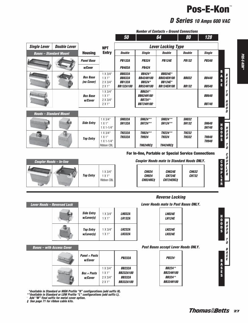
50 64 80 128
Lever Locking Type
Box Basew/Cover
Side Entry
Top Entry
NPTBases – Standard Mount Entry Double Single Double Double Single
Panel Base PB132A PB324 PB124E PB132 PB348
w/Cover PB403A PB424
1 X 3/4" BB032A BB424* BB024E*1 X 1" BB832A BB424H100 BB024EH100 BB032 BB4482 X 3/4" BB132A BB524* BB124E*2 X 1" BB132A100 BB524H100 BB124EH100 BB132 BB548
1 X 3/4" BB624* n
1 X 1" BB624H100 n BB6482 X 3/4" BB724* n
2 X 1" BB724H100 n BB748
Number of Contacts + Ground Connections
Box Base(no Cover)
For In-line, Portable or Special Service Connections
Coupler Hoods – In-line
1 X 3/4" CH824 CH624E CH6321 X 1" CH924 CH724E CH732
Ribbon CBL CH824RC‡ CH724ERC‡Top Entry
LH024ELH124E
LH224ELH324E
Coupler Hoods mate to Standard Hoods ONLY.
Lever Hoods mate to Post Bases ONLY.
PB224 n
BB224*n
BB224H100BB324*n
BB324H100
Panel + Postsw/Cover
Box + Postsw/Cover
Post Bases accept Lever Hoods ONLY.
**Available in Standard or HIGH Profile “H” configurations (add suffix H).**Available in Standard or LOW Profile “L” configurations (add suffix L).n Add “M” final suffix for metal cover option.‡ See page 71 for ribbon cable kits.
Hoods – Standard Mount1 X 3/4" SH032A SH624** SH024** SH0321 X 1" SH132A SH724** SH124** SH132 SH6481 X 1-1/4" SH748
1 X 3/4" TH232A TH824** TH224** TH2321 X 1" TH332A TH924** TH324** TH332 TH8481 X 1-1/4" TH948
Ribbon CBL TH624RC‡ TH424RC‡
BASE
BASE
TO
HOOD
HOOD
TO
COUPLER
COUPLER
HOOD
TO
BASE
HOODS
HOODS
BASES
Top Entryw/Lever(s)
Side Entryw/Lever(s)
Lever Hoods – Reversed Lock
1 X 3/4" LH032A1 X 1" LH132A
1 X 3/4" LH232A1 X 1" LH332A
Bases – with Access Cover
PB232A
1 X 3/4" BB232A1 X 1" BB232A1002 X 3/4" BB332A2 X 1" BB332A100
Reverse Locking
Housing
Single Lever Double Lever
21-30.pdf 7 1/5/2012 2:45:54 PM1-76.pdf 27 1/6/2012 10:52:56 AM

Pos-E-Kon™
DD Series 10 Amps 600 VAC
28
Install toMatching Series
Hood/Base
Crimp Terminal Inserts 24 + G 42 + G 72 + G
Male InsertMC224DD MC242DD MC272DD
(Order contacts below)
Female InsertFC124DD FC142DD FC172DD
(Order contacts below)
24 42 72 24, 42, 72 Contacts + Ground
Contacts Selection Chart
Crimp Contacts Wire Gauge AWG (mm2) Identification Female Male
22+ AWG (0.14-0.37 mm2) 1 FP22SD MP22SD
20 AWG (0.5 mm2) 2 FP20SD MP20SD
18 AWG (0.75-1 mm2) 3 FP18SD MP18SD
16 AWG (1.5 mm2) 4 FP16SD MP16SD
14 AWG (2.5 mm2) 5 FP14SD MP14SD
Adapter Mount Frames allow “open”wiring inside closed panel enclosure.They also allow Inserts to be assembledas a separable Terminal Block device.
DIN Rail Adapter Mount Frames 24 + G 42 + G 72 + G
150 mm long, with baseAMF106 AMF110 AMF116
for snapping onto DIN rail
125 mm long style AMF006 AMF010 AMF016
150 mm long; doubleAMF112
for Dual Inserts Mounting
See page 72 for POF installation and tools info.
Fiber Optic Contacts
Crimp Contacts Wire Gauge AWG (mm2) Female Male
Fiber Optic Cable, Size 1 mm FPF520 MPF530
For all Inserts
WT80
Crimp Tool
RT614
Extraction ToolI.D.
For all Crimp Terminal “DD” Inserts
21-30.pdf 8 1/5/2012 2:45:54 PM1-76.pdf 28 1/6/2012 10:52:56 AM

29
Pos-E-Kon™
DD Series 10 Amps 600 VAC
POS-E-KONTM
Box Basew/Cover
Box Base(no Cover)
24 42 72
Lever Locking Type
Side Entry
Top Entry
Number of Contacts + Ground Connection
Housing
Hoods – Standard Mount1 X 1/2" SH606 SH610 SH0101 X 3/4" SH606H075 SH610H075 SH010H075 SH616u SH016u1 X 1" SH606H100 SH610H100 SH010H100 SH716u SH116H
1 X 1/2" TH806 TH810 TH2101 X 3/4" TH806H075 TH810H075 TH210H075 TH816u TH216u1 X 1" TH806H100 TH810H100 TH210H100 TH816H100 TH316H
Ribbon CBL TH816RC‡ TH216RC‡
For In-line, Portable or Special Service Connections
Top Entryw/Lever(s)
* Available in Standard or HIGH Profile “H” configurations (add suffix H).n Add “M” final suffix for metal cover option.u Both HIGH (H) and LOW (L) profile also available (add suffix H or L).‡ See page 71 for ribbon cable kits.
Coupler Hoods – In-line Coupler Hoods mate to Standard Hoods ONLY.
1 X 1/2" CH806 CH810 CH610E1 X 3/4" CH806H075 CH810H075 CH610EH075 CH816H CH616EH1 X 1" CH806H100 CH810H100 CH610EH100 CH916H CH716EH
Ribbon CBL CH816RC‡ CH616ERC‡
BASE
BASE
TO
HOOD
HOOD
TO
COUPLER
COUPLER
HOODS
NPTBases – Standard Mount Entry Single Single Double Single Double
Panel Base PB306 n PB310 n PB110E PB316 PB116E
w/Cover PB406 n PB410 n PB416
1 X 1/2" BB406 BB410 BB010E1 X 3/4" BB406H075 BB410H075 BB010EH075 BB416* BB016E*1 X 1" BB406H100 BB410H100 BB010EH100 BB416H100 BB016EH1002 X 1/2" BB506 BB510 BB110E2 X 3/4" BB506H075 BB510H075 BB110EH075 BB516* BB116E*2 X 1" BB506H100 BB510H100 BB110EH100 BB516H100 BB116EH100
1 X 1/2" BB606 n BB610 n
1 X 3/4" BB606H075 n BB610H075 n BB616* n
1 X 1" BB606H100 n BB610H100 n BB616H100 n
2 X 1/2" BB706 n BB710 n
2 X 3/4" BB706H075 n BB710H075 n BB716* n
2 X 1" BB706H100 n BB710H100 n BB716H100 n
LH010ELH010EH075 LH016E*LH010EH100 LH116EH
LH210ELH210EH075 LH216E*LH210EH100 LH316EH
PB210 n PB216 n
BB210 n
BB210H075 n BB216* n
BB210H100 n BB216H100 n
BB310n
BB310H075 n BB316* n
BB310H100 n BB316H100 n
Post Bases accept Lever Hoods ONLY.
Side Entryw/Lever(s)
Top Entryw/Lever(s)
Box + Postsw/Cover
Lever Hoods mate to Post Bases ONLY.
HOOD
TO
BASE
HOODS
BASES
Bases – with Access Cover
Panel + Postsw/Cover
1 X 1/2"1 X 3/4"1 X 1"2 X 1/2"2 X 3/4"2 X 1"
Lever Hoods – Reversed Lock1 X 1/2"1 X 3/4"1 X 1"
1 X 1/2"1 X 3/4"1 X 1"
Reverse Locking
Single Lever Double Lever
21-30.pdf 9 1/5/2012 2:45:55 PM1-76.pdf 29 1/6/2012 10:52:56 AM

Pos-E-Kon™
DD Series 10 Amps 600 VAC
30
Install toMatching Series
Hood/Base
Crimp Terminal Inserts 108 + G 144 + G 216 + G
Male InsertMC208DD
MC272DD+ MC208DD+(Order contacts below) MC244DD MC216DD
Female InsertFC108DD
FC172DD+ FC108DD+(Order contacts below) FC144DD FC116DD
108 144 216 108, 144 & 216 Contacts + Ground
Contacts Selection
Crimp Contacts Wire Gauge AWG (mm2) Identification Female Male
22+ AWG (0.14-0.37 mm2) 1 FP22SD MP22SD
20 AWG (0.5 mm2) 2 FP20SD MP20SD
18 AWG (0.75-1 mm2) 3 FP18SD MP18SD
16 AWG (1.5 mm2) 4 FP16SD MP16SD
14 AWG (2.5 mm2) 5 FP14SD MP14SD
Adapter Mount Frames allow “open” wiringinside closed panel enclosure. They also allowInserts to be assembled as a separableTerminal Block device.
See page 72 for POF installation and tools info.
Fiber Optic Contacts
Crimp Contacts Wire Gauge AWG (mm2) Female Male
Fiber Optic Cable, Size 1 mm FPF520 MPF530
For all Crimp Terminal “DD”Inserts
For all Inserts
DIN Rail Adapter Mount Frames 108 + G
150 mm long, with baseAMF124
for snapping onto DIN rail
WT80
Crimp Tool
RT614
Extraction ToolI.D.
21-30.pdf 10 1/5/2012 2:45:55 PM1-76.pdf 30 1/6/2012 10:52:56 AM

31
Pos-E-Kon™
DD Series 10 Amps 600 VAC
POS-E-KONTM
NPTBases – Standard Mount Entry Single Double Double Single
Panel Base PB324 PB124E PB132 PB348
w/Cover PB424 n PB448
1 X 3/4" BB424* BB024E*Box Base 1 X 1" BB424H100 BB024EH100 BB032 BB448
( no Cover ) 2 X 3/4" BB524* BB124E*2 X 1" BB524H100 BB124EH100 BB132 BB548
1 X 3/4" BB624* n
Box Base 1 X 1" BB624H100 n BB648w/Cover 2 X 3/4" BB724* n
2 X 1" BB724H100 n BB748
Hoods – Standard Mount1 X 3/4" **SH624** *SH024** SH0321 X 1" SH724** SH124** SH132 SH6481 X 1-1/4" SH132-125 SH748
1 X 3/4" **TH824** **TH224** TH2321 X 1" TH924 TH324 TH332 TH8481 X 1-1/4" TH332-125 TH948
Ribbon CBL TH624RC‡ TH424RC‡
Coupler Hoods – In-line Service Coupler Hoods mate to Standard Hoods ONLY.
1 X 3/4" CH824 CH624E CH6321 X 1" CH924 CH724E CH732
Ribbon CBL CH824RC‡ CH624ERC‡
Lever Locking TypeHousing
Side Entry
Top Entry
For In-line, Portable or Special Service Connections
108 144 216
Top Entry
BASE
BASE
TO
HOOD
HOOD
TO
COUPLER
COUPLER
HOODS
LH024ELH124E
LH224ELH324E
PB224 n
BB224*n
BB224H100BB324*n
BB324H100
Post Bases accept Lever Hoods ONLY.
**Available in Standard or HIGH Profile “H” configurations (add suffix H).**Available in Standard or LOW Profile “L” configurations (add suffix L).n Add “M” final suffix for metal cover option.‡ See page 71 for ribbon cable kits.
Lever Hoods mate to Post Bases ONLY.
HOOD
TO
BASE
HOODS
BASES
Bases – with Access Cover
Panel Basew/Posts + Cover
1 X 3/4"Box Base 1 X 1"
w/Posts + Cover 2 X 3/4"2 X 1"
Lever Hoods – Rev. Lock
Side Entry 1 X 3/4"w /Lever(s) 1 X 1"
Top Entry 1 X 3/4"w/Lever(s) 1 X 1"
Reverse Locking
Number of Contacts + Ground Connections
Single Lever Double Lever
31-40.pdf 1 1/5/2012 2:46:05 PM1-76.pdf 31 1/6/2012 10:52:56 AM

Pos-E-Kon™
K Series 80 + 16 Amps 600 VAC
32
4 Contacts @ 80A + 8 Contacts @ 16A8 Contacts @ 80A + 16 Contacts @ 16A+ Ground
Install toMatching Series
Hood/Base
Wiring Note: 6 AWG (16mm2) for 80A Contacts14 AWG (2.5mm2) for 16A Contacts
4 @80A +8 @16A + G
8 @80A +16 @16A + G
Screw Terminal Contact Carrier Inserts 4 @80A+ 8 @80A+8 @216A+G 16 @16A+G
Male – Pins MS212K MS212K (x2)
Female – Sleeves FS112K FS112K (x2)
Other Configurations
Special order high amperage and/or combo configurations may beavailable. Contact your RegionalSales Office.
31-40.pdf 2 1/5/2012 2:46:05 PM1-76.pdf 32 1/6/2012 10:52:56 AM

33
Pos-E-Kon™
K Series 80 + 16 Amps 600 VAC
POS-E-KONTM
NPTBases – Standard Mount Entry Single Double Single
Panel Base PB324 PB124E PB348
w/Cover PB424
1 X 3/4" BB424* BB024E*Box Base 1 X 1" BB424H100 BB024EH100 BB448
( no Cover ) 2 X 3/4" BB524* BB124E*2 X 1" BB524H100 BB124EH100 BB548
1 X 3/4" BB624 n*Box Base 1 X 1" BB624H100 n BB648w/Cover 2 X 3/4" BB724 n*
2 X 1" BB724H100 n BB748
LH024ELH124E
LH224ELH324E
PB224 n
BB224 n*BB324 n*
Post Bases accept Lever Hoods ONLY.
Lever Locking TypeHousing
Side Entry
Top Entry
For In-line, Portable or Special Service Connections
Coupler Hoods – In-line Coupler Hoods mate to Standard Hoods ONLY.
1 X 3/4" CH824 CH624E1 X 1" CH924 CH724E
Top Entry
K-12 K-248 @16A + G 16 @16A, + G4 @80A + G 8 @80A + G
Lever Hoods mate to Post Bases ONLY.
Number of Contacts + Ground Connection
Box Basew/Posts + Cover
BASE
BASE
TO
HOOD
HOOD
TO
COUPLER
COUPLER
HOOD
TO
BASE
HOODS
HOODS
BASES
Bases – with Access Cover
Panel Basew/Posts + Cover
1 X 3/4"2 X 3/4"
Lever Hoods – Rev. Lock
Side Entry 1 X 3/4"w/Lever(s) 1 X 1"
Top Entry 1 X 3/4"w/Lever(s) 1 X 1"
Hoods – Standard Mount1 X 3/4" SH624** SH024**1 X 1" SH724** SH124** SH6481 X 1-1/4" SH748
1 X 3/4" TH824** TH224**1 X 1" TH924** TH324** TH8481 X 1-1/4" TH948
Reverse Locking
**Available in Standard or HIGH Profile “H” configurations (add suffix H).**Available in Standard or LOW Profile “L” configurations (add suffix L).n Add “M” final suffix for metal cover option.
Single Lever Double Lever
31-40.pdf 3 1/5/2012 2:46:06 PM1-76.pdf 33 1/6/2012 10:52:56 AM

Pos-E-Kon™
V Series 16 Amps 600 VAC
34
Crimp Tool
3, 6, 10, 16, 20, 26 & 32 Contacts+ Control Contacts & Ground
Install toMatching Series
Hood/Base
Screw Terminal Inserts 3 + G 6 + G+ 2 Control + 2 Control
Male – PinsMS203V MS206V
20-14 AWG (0.5-2.5 mm2)
Female – SleevesFS103V FS106V
20-14 AWG (0.5-2.5 mm2)
Crimp Terminal Inserts 3 + G 6 + G+ 2 Control + 2 Control
Male InsertMC403V MC406V
(Order contacts below)
Female InsertFC303V FC306V
(Order contacts below)
Crimp Contacts Wire AWG (mm2) Identification Female Male Switch/Control
20 AWG (0.5 mm2) No Groove FP2000 MP2000 –
18 AWG (0.75-1 mm2) 1 Groove FP1800 MP1800 CP1800
16 AWG (1.5 mm2) 2 Grooves FP1600 MP1600 CP1600
14 AWG (2.5 mm2) 3 Grooves FP1400 MP1400 CP1400
12 AWG (4.0 mm2) No Groove FP1200 MP1200 –
DIN Rail Adapter Mount Frames 3 + G 6 + G+ 2 Control + 2 Control
125mm long, with base for AMF010 AMF016
snapping onto DIN rail
150mm long, with base for AMF110 AMF116
snapping onto DIN railF
Adapter Mount Frames allow “open”wiring inside closed panel enclosure.They also allow Inserts to be assembledas a separable Terminal Block device.
3 + G+ 2 Control
6 + G+ 2 Control
Contacts Selection
ControlContacts
Make Last,Break First
WT611TB
Use small blade screwdriver to pushin wire entry tab for easy contactremoval.
Groove
For all Inserts
For “V” Series Inserts
31-40.pdf 4 1/5/2012 2:46:06 PM1-76.pdf 34 1/6/2012 10:52:56 AM
35
Pos-E-Kon™
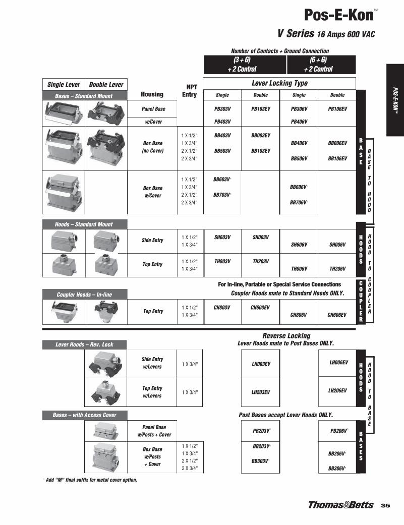
V Series 16 Amps 600 VAC
POS-E-KONTM
NPTBases – Standard Mount Entry Single Double Single Double
Panel Base PB303V PB103EV PB306V PB106EV
w/Cover PB403V PB406V
1 X 1/2" BB403V BB003EV1 X 3/4" BB406V BB006EV2 X 1/2" BB503V BB103EV2 X 3/4" BB506V BB106EV
1 X 1/2" BB603V n
1 X 3/4" BB606V n
2 X 1/2" BB703V n
2 X 3/4" BB706V n
Hoods – Standard Mount
1 X 1/2" SH603V SH003V1 X 3/4" SH606V SH006V
1 X 1/2" TH803V TH203V1 X 3/4" TH806V TH206V
Coupler Hoods – In-line Coupler Hoods mate to Standard Hoods ONLY.
1 X 1/2" CH803V CH603EV1 X 3/4" CH806V CH606EV
LH003EV
LH203EV
PB203V n
BB203V n
BB303V n
Post Bases accept Lever Hoods ONLY.
Lever Locking TypeHousing
Side Entry
Top Entry
For In-line, Portable or Special Service Connections
Lever Hoods mate to Post Bases ONLY.
Top Entry
Number of Contacts + Ground Connection(3 + G)
+ 2 Control(6 + G)
+ 2 Control
Box Base(no Cover)
Box Basew/Cover
Side Entryw/Levers
Top Entryw/Levers
LH006EV
LH206EV
Box Basew/Posts+ Cover
PB206V n
BB206V n
BB306V n
BASE
BASE
TO
HOOD
HOOD
TO
COUPLER
COUPLER
HOOD
TO
BASE
HOODS
HOODS
BASES
Bases – with Access Cover
Panel Basew/Posts + Cover
1 X 1/2"1 X 3/4"2 X 1/2"2 X 3/4"
Lever Hoods – Rev. Lock
1 X 3/4"
1 X 3/4"
Reverse Locking
n Add “M” final suffix for metal cover option.
Single Lever Double Lever
31-40.pdf 5 1/5/2012 2:46:06 PM1-76.pdf 35 1/6/2012 10:52:56 AM

Pos-E-Kon™
V Series 16 Amps 600 VAC
36
Crimp Tool Contacts Selection
3, 6, 10, 16, 20, 26 & 32 Contacts+2 Control Contacts & Ground
Install toMatching Series
Hood/Base
Screw Terminal Inserts10 + G 16 + G 20 + G 26 + G 32 + G
+2 Control +2 Control +2 Control +2 Control +2 Control
Male – PinsMS210V MS216V FS110V x2
MS210V+2x MS216V
20-14 AWG (0.5-2.5 mm2) MS216V
Female – SleevesFS110V FS116V FS210V x2
FS110V+2x FS116V
20-14 AWG (0.5-2.5 mm2) FS116V
Crimp Contacts Wire AWG (mm2) Identification Female Male Switch/Control
20 AWG (0.5 mm2) No Groove FP2000 MP2000 –
18 AWG (0.75-1 mm2) 1 Groove FP1800 MP1800 CP1800
16 AWG (1.5 mm2) 2 Grooves FP1600 MP1600 CP1800
14 AWG (2.5 mm2) 3 Grooves FP1400 MP1400 CP1400
12 AWG (4.0 mm2) No Groove FP1200 MP1200 –
DIN Rail Adapter Mount Frames 10 + G 16 + G
150mm long, with base AMF124 AMF124for snapping onto DIN rail
Adapter Mount Framesallow “open” wiringinside closed panel enclosure. They alsoallow Inserts to beassembled as a separableTerminal Block device.
10 + G+ 2 Control
16 + G+ 2 Control
20 + G+ 2 Control
26 + G+ 2 Control
32 + G+ 2 Control
Crimp Terminal Inserts10 + G 16 + G 20 + G 26 + G 32 + G
+2 Control +2 Control +2 Control +2 Control +2 Control
Male InsertMC410V MC416V MC410V x2
MC410V+2x MC416V
(Order contacts below) MC416V
Female InsertFC310V FC316V FC310V x2
FC310V+2x FC316V
(Order contacts below) FC316V
WT611TB
Use small bladescrewdriver to push inwire entry tab for easycontact removal.
Grooves
For all “V” Series Inserts
31-40.pdf 6 1/5/2012 2:46:06 PM1-76.pdf 36 1/6/2012 10:52:56 AM

37
Pos-E-Kon™
V Series 16 Amps 600 VAC
POS-E-KONTM
Hoods – Standard Mount1 X 3/4" SH010V1 X 1" SH010V100 SH6481 X 1-1/4" SH748
1 X 1/2" TH210V1 X 3/4" TH8481 X 1" TH948
Post Bases accept Lever Hoods ONLY.
Lever Locking TypeHousing
Side Entry
Top Entry
Lever Hoods mate to Post Bases ONLY.
Top Entry
Number of Contacts + Ground ConnectionV10: (10 + G) or (16 + G)
+ 2 ControlV20: (20 + G) or (26 + G)or (32 + G) + 2 Control
Box Base(no Cover)
Box Basew/Cover
Side Entryw/Levers
Top Entryw/Levers
Box Basew/Posts + Cover
BASE
BASE
TO
HOOD
HOOD
TO
COUPLER
COUPLER
HOOD
TO
BASE
HOODS
HOODS
BASES
Bases – with Access Cover
Panel Basew/Posts + Cover
PB210V n
1 X 3/4" BB210V n
2 X 3/4" BB310V n
Lever Hoods – Rev. Lock
1 X 3/4" LH010EV
1 X 3/4" LH210EV1 X 1" LH210V100
For In-line, Portable or Special Service Connections
Coupler Hoods – In-line Coupler Hoods mate to Standard Hoods ONLY.
1 X 3/4" CH610EV1 X 1" CH610EV1001 X 1-1/4" CH610EV125
Reverse Locking
Single Lever Double Lever NPTBases – Standard Mount Entry Double Single
PB110EV PB348Panel Base
w/Cover PB448V
1 X 3/4" BB010EV1 X 1" BB4482 X 3/4" BB110EV2 X 1" BB548
1 X 3/4" 1 X 1" BB6482 X 3/4" 2 X 1" BB748
31-40.pdf 7 1/5/2012 2:46:07 PM1-76.pdf 37 1/6/2012 10:52:56 AM

Pos-E-Kon™
T Series 16 Amps 600 VAC
38
• High Temp 200°C Components• Corrosion Resistant
Housings
6 10 16 246, 10, 16 & 24 Contacts + Ground
Install toMatching Series
Hood/Base
Screw Terminal Inserts 6 + G 10 + G 16 + G 24 + G
Male – PinsMS206T MS210T MS216T MS224T
20-14 AWG (0.5-2.5 mm2)
Female – SleevesFS106T FS110T FS116T FS124T
20-14 AWG (0.5-2.5 mm2)
T Series Benefits• High temp 200°C rated inserts• Silicone Viton® seals for molded edge gaskets*• Corrosion resistant copper-free aluminum housings with special finish• New ergonomic thermoplastic handles rated UL94V-O • Electrostatic epoxy powder coated finish
*Viton is a trademark of DuPont Dow Elastomers.
31-40.pdf 8 1/5/2012 2:46:07 PM1-76.pdf 38 1/6/2012 10:52:56 AM

39
Pos-E-Kon™
T Series 16 Amps 600 VAC
POS-E-KONTM
Box Base (no Cover)
Lever Locking TypeHousing
6 10 16 24Number of Contacts + Ground Connection
High Temp 200°C
Hoods – Standard Mount1 X 16 SH606T SH010T1 X 21 SH016T SH024T1 X 29 SH124T
1 X 16 TH806T TH210T1 X 21 TH216T TH224T1 X 29 TH324T
Coupler Hoods – In-line Coupler Hoods mate to Standard Hoods ONLY.
1 X 16 CH806T CH610ET1 X 21 CH616ET CH624ET1 X 29 CH716ET CH724ET
Side Entry
Top Entry
For In-line, Portable or Special Service Connections
Top Entry
BASE
BASE
TO
HOOD
HOOD
TO
COUPLER
COUPLER
HOODS
Note: Hoods and Bases are green colored to denote special T series.
Bases – Standard Mount Single Double Double Double
Panel Base PB306T PB110ET PB116ET PB124ET
1 X 16 BB406T BB010ET1 X 21 BB016ET BB024ET2 X 16 BB506T BB110ET2 X 21 BB116ET BB124ET
Single Lever Double LeverPg
MetricEntry
31-40.pdf 9 1/5/2012 2:46:07 PM1-76.pdf 39 1/6/2012 10:52:56 AM

Pos-E-Kon™
M Series
40
Mix and Match Modular Connections• Signal, fiber optic, control and power connections
all in one connection point.
• 2, 3, 5 and 7 slot insert holders provide unlimitedflexibility.
• Standard single inserts:
› 3 pole Coax Signal› 3 pole, 50A, 600 VAC› 4 pole +G, 5 pole 16A, 600VAC› 5 pole, 20A, 400VAC› 10 pole, 10A, 250VAC or 10 pole, POF
(fiber optic)› 20 pole, 5A, 63VAC › Dummy block
• Standard B series Hoods and Bases
How to Specify© Select types of contacts/circuits (see above).
© Select number of each (per insert above).
© Add up to get holder sizee.g.: 2-POF + 2-50A + 8-10A = 3 inserts plus 3-slot holders.
© Match holder size required to hood and baseoptions (mating).
Easy insert removalContacts + Inserts + Insert Holder + Housing
31-40.pdf 10 1/5/2012 2:46:08 PM1-76.pdf 40 1/6/2012 10:52:56 AM

41
Pos-E-Kon™
M (3P Coax) Series 1.5 Amps 50 VAC
POS-E-KONTM
Tools
Dummy Inserts 0
Male Blind Insert: MC100Mfor place keeping in Insert Holder
Female Blind Insert: FC000M
for place keeping in Insert Holder
Male Crimp Contacts
Coax Pin & Sleeve 3 Positions
Male Coax Pin Contact MCX500
RG-174Cable Size/Type RG-179
RG-316
Male Coax Pin Cotact MCX510
Cable Size/Type RG-58
Female Coax Pin Contact FCX400
RG-174Cable Size/Type RG-179
RG-316
Female Coax Pin Cotact FCX410
Cable Size/Type RG-58
Specifications
Number of Poles 3
Termination Method Crimp (or solder)
Contacts Solid Drilled,3.6mm CoAxialCopper Alloy, GoldPlated
Rated Current 1.5A
Rated Voltage 50V
Volume Resistance ≤6 milliohms
Surge Impedance 50 Ohms
Frequency Range 2 GHz
Crimp Terminal Inserts 3P CoAx
Male Insert MC303M
Female Insert FC203M
Female Crimp Contacts
Crimping Tool CT700TB
RG174, 179, 316 Crimp Die CD710TBRG58 Crimp Die CD720TB
Contact Removal Tool RT000TB
Insert Puller PT300TB
Inserts
Contacts
41-45.pdf 1 1/5/2012 2:46:18 PM1-76.pdf 41 1/6/2012 10:52:56 AM

Pos-E-Kon™
M (3P) Series 50 Amps 600 VAC
42
Female Crimp Pins
Male Crimp PinsTools
Pin & Sleeve 3 Positions
1.5 mm2 16 AWG MP16SD50
2.5 mm2 14 AWG MP14SD50
4 mm2 12 AWG MP12SD50
6 mm2 10 AWG MP10SD50
10 mm2 8 AWG MP08SD50
Specifications
Number of Poles 3
Termination Method Crimp
Contacts Solid Drilled, 3.6mmCopper Alloy, SilverPlated
Rated Current 50 Amp
Rated Voltage 600V
Rated Impulse Voltage 8.0 kV
Test Voltage 4 kV
Volume Resistance ≤1 milliohm
1.5 mm2 16 AWG FP16SD50
2.5 mm2 14 AWG FP14SD50
4 mm2 12 AWG FP12SD50
6 mm2 10 AWG FP10SD50
10 mm2 8 AWG FP08SD50
Dummy Inserts 0
Male Blind Insert: MC100Mfor place keeping in Insert Holder
Female Blind Insert: FC000M
for place keeping in Insert Holder
Crimp Terminal Inserts 3P
Male Insert MC103M
Female Insert FC003M
Crimping Tool CT400TB
RG174, 179, 316 Crimp Die CD710TB
Contact Removal Tool RT000TB
Insert Puller PT300TB
Inserts
Contacts
41-45.pdf 2 1/5/2012 2:46:18 PM1-76.pdf 42 1/6/2012 10:52:56 AM

43
Pos-E-Kon™
M (4/5P) Series 16 Amps 600 VAC
POS-E-KONTM
Female Crimp Pins
Male Crimp Pins
Crimp Terminal Inserts 4P +G
Male Insert MC704M
Female Insert FC604M
CrimpingCT700TB
Tool
Crimping 20 – 16 AWG CD730TBDie 16 – 14 AWG CD740TB
Contact 20 – 16 AWG CL010TBLocator 16 – 14 AWG CL020TB
RT800TB
PT300TB
Pin & Sleeve
0.5 – 1.5 mm2 20 – 16 AWG MP16RF16
1.5 – 2.5 mm2 16 – 14 AWG MP14RF16
2.5 – 4 mm2 12 AWG MP12RF16
Specifications
Number of Poles 4 +G5
Termination Method Crimp
Contacts Stamped & Rolled,2.5 mm CopperAlloy, Silver Plated
Rated Current 16A
Rated Voltage 600V
Rated Impulse Voltage 8.0 kV
Test Voltage 5.7 kV
Volume Resistance ≤5 milliohms
0.5 – 1.5 mm2 20 – 16 AWG FP16RF16
1.5 – 2.5 mm2 16 – 14 AWG FP14RF16
2.5 – 4 mm2 12 AWG FP12RF16
Dummy Inserts 0
Male Blind Insert: MC100Mfor place keeping in Insert Holder
Female Blind Insert: FC000M
for place keeping in Insert Holder
Tools
Crimp Terminal Inserts 5P
Male Insert MC705M
Female Insert FC605M
ContactRemoval
Tool
InsertPuller
Inserts
Contacts
4&5 Positions
41-45.pdf 3 1/5/2012 2:46:18 PM1-76.pdf 43 1/6/2012 10:52:56 AM

Pos-E-Kon™
M (5P) Series 20 Amps 400 VAC
44
Female Crimp Pins
Male Crimp Pins
Pin & Sleeve 5 Positions
Crimp Terminal Inserts 5P
Male Insert MC105M
Female Insert FC005M
0.5 mm2 20 AWG MP20SD20
1.0 mm2 18 AWG MP18SD20
1.5 mm2 16 AWG MP16SD20
2.5 mm2 14 AWG MP14SD20
4 mm2 12 AWG MP12SD20
Specifications
Number of Poles 5
Termination Method Crimp
Contacts Solid Drilled, 2.5 mmCopper Alloy, SilverPlated
Rated Current 20A
Rated Voltage 400V
Rated Impulse Voltage 6.0 kV
Test Voltage 3.5 kV
Volume Resistance ≤2 milliohms
0.5 mm2 20 AWG FP20SD20
1.0 mm2 18 AWG FP18SD20
1.5 mm2 16 AWG FP16SD20
2.5 mm2 14 AWG FP14SD20
4 mm2 12 AWG FP12SD20
Dummy Inserts 0
Male Blind Insert: MC100Mfor place keeping in Insert Holder
Female Blind Insert: FC000M
for place keeping in Insert Holder
Inserts
Contacts
CrimpingCT700TB
Tool
Crimping 20 – 14 AWG CD750TBDie 12 AWG CD760TB
Contact 20 – 14 AWG CL430TBLocator 12 AWG CL040TB
RT000TB
PT300TB
Tools
ContactRemoval
Tool
InsertPuller
41-45.pdf 4 1/5/2012 2:46:18 PM1-76.pdf 44 1/6/2012 10:52:57 AM
45
Pos-E-Kon™
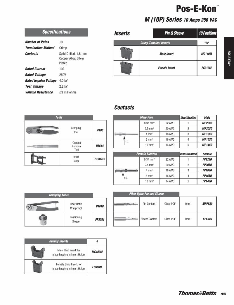
M (10P) Series 10 Amps 250 VAC
POS-E-KONTM
Pin Contact Glass POF 1mm MPF530
Sleeve Contact Glass POF 1mm FPF520
Pin & Sleeve 10 Positions
Identification Male
0.37 mm2 22 AWG 1 MP22SD
2.5 mm2 20 AWG 2 MP20SD
4 mm2 18 AWG 3 MP18SD
6 mm2 16 AWG 4 MP16SD
10 mm2 14 AWG 5 MP14SD
Specifications
Number of Poles 10
Termination Method Crimp
Contacts Solid Drilled, 1.6 mmCopper Alloy, SilverPlated
Rated Current 10A
Rated Voltage 250V
Rated Impulse Voltage 4.0 kV
Test Voltage 2.2 kV
Volume Resistance ≤3 milliohms
Fiber Optic Pin and Sleeve
Identification Female
0.37 mm2 22 AWG 1 FP22SD
2.5 mm2 20 AWG 2 FP20SD
4 mm2 18 AWG 3 FP18SD
6 mm2 16 AWG 4 FP16SD
10 mm2 14 AWG 5 FP14SD
Crimp Terminal Inserts 10P
Male Insert MC110M
Female Insert FC010M
Female Sleeves
Dummy Inserts 0
Male Blind Insert: for MC100Mplace keeping in Insert Holder
Female Blind Insert: for FC000Mplace keeping in Insert Holder
Tools
CrimpingWT80
Tool
RT614
InsertPT300TB
Puller
Crimping Tools
Fiber OpticCT610
Crimp Tool
PositioningFPS701
Sleeve
I.D.
I.D.
Male Pins
ContactRemoval
Tool
Inserts
Contacts
41-45.pdf 5 1/5/2012 2:46:18 PM1-76.pdf 45 1/6/2012 10:52:57 AM

Pos-E-Kon™
M(20P) Series 5 Amps 63 VAC
46
Male Pins
CrimpingCT500TB
Tool
RT200TB
InsertPT300TB
Puller
Pin & Sleeve 20 Positions
0.25 mm2 28-24 AWG MP24GS
0.5 mm2 24-20 AWG MP20GS
Specifications
Number of Poles 20
Termination Method Crimp
Contacts Stamped, Formed,1.0 mm Copper Alloy,Gold Plated
Rated Current 5A
Rated Voltage 63V
Rated Impulse Voltage 4.0 kV
Test Voltage 1.68 kV
Volume Resistance ≤5 milliohms
Tools
0.25 mm2 28-24 AWG FP24GS
0.5 mm2 24-20 AWG FP20GS
Crimp Terminal Inserts 20P
Male Insert MC120M
Female Insert FC020M
Female Sleeves
Dummy Inserts 0
Male Blind Insert: for MC100Mplace keeping in Insert Holder
Female Blind Insert: for FC000Mplace keeping in Insert Holder
ContactRemoval
Tool
Inserts
Contacts
46-50.pdf 1 1/5/2012 2:46:28 PM1-76.pdf 46 1/6/2012 10:52:57 AM

47
Pos-E-Kon™
M Series B6 Housing 600 VAC: 2 Inserts
POS-E-KONTM
n Add “M” final suffix for metal cover option.
Lever Locking Type
Housing
Side Entry
Top Entry
For In-line, Portable or Special Service Connections
Coupler Hoods Coupler Hoods mate to Standard Hoods ABOVE.
1 X 1/2" CH8061 X 3/4" CH806H0751 X 1" CH806H100
Top Entry
Insert Holders + HousingsSelect one each male and female 2-slot insert holders for B6 housings, then
select two each of any male and female M series inserts from pp. 41-46.
Hoods – Standard Mount
1 X 1/2" SH6061 X 3/4" SH606H0751 X 1" SH606H100
1 X 1/2" TH8061 X 3/4" TH806H0751 X 1" TH806H100
2-slot Female Insert Holder
F2F006M
2-slot Male Insert Holder
F2M106M
BASE
BASE
TO
HOOD
HOOD
TO
COUPLER
COUPLER
HOODS
NPTBases – Standard Mount Entry Single
Panel Base PB306 n
w/Cover PB406 n
1 X 1/2" BB4061 X 3/4" BB406H075
Box Base 1 X 1" BB406H100( no Cover ) 2 X 1/2" BB506
2 X 3/4" BB506H0752 X 1" BB506H100
1 X 1/2" BB606 n
1 X 3/4" BB606H075 n
Box Base 1 X 1" BB606H100 n
w/Cover 2 X 1/2" BB706 n
2 X 3/4" BB706H075 n
2 X 1" BB706H100 n
Single Lever
46-50.pdf 2 1/5/2012 2:46:28 PM1-76.pdf 47 1/6/2012 10:52:57 AM

Pos-E-Kon™
M Series B10 Housing 600 VAC: 3 Inserts
48
Lever Locking TypeHousing
Side Entry
Top Entry
For In-line, Portable or Special Service Connections
Coupler Hoods – In-line Coupler Hoods mate to Standard Hoods.
1 X 1/2" CH810 CH610E1 X 3/4" CH810H075 CH610EH0751 X 1" CH810H100 CH610EH100
Top Entry
Select one each male and female 3-slot insert holders for B10 housings, then select three each of any male and female M series inserts from pp. 41-46.
Hoods – Standard Mount1 X 1/2" SH610 SH0101 X 3/4" SH610H075 SH010H0751 X 1" SH610H100 SH010H100
1 X 1/2" TH810 TH2101 X 3/4" TH810H075 TH210H0751 X 1" TH810H100 TH210H100
3-slot Female Insert Holder
F3F010M
3-slot Male Insert Holder
F3M110M Side Entryw/Lever(s)
Top Entryw/Lever(s)
PB210 n
BB210 n
BB210H075 n
BB210H100 n
BB310 n
BB310H075 n
BB310H100 n
Post Bases accept Lever Hoods ONLY.
Box + Postsw/Cover
BASE
BASE
TO
HOOD
HOOD
TO
COUPLER
COUPLER
HOOD
TO
BASE
HOODS
HOODS
BASES
Lever Hoods – Reversed Lock Lever Hoods mate to Post Bases ONLY.
1 X 1/2" LH010E1 X 3/4" LH010EH0751 X 1" LH010EH100
1 X 1/2" LH210E1 X 3/4" LH210EH0751 X 1" LH210EH100
Reverse Locking
NPTBases – Standard Mount Entry Single Double
Panel Base PB310 PB110E
w/Cover PB410
1 X 1/2" BB410 BB010E1 X 3/4" BB410H075 BB010EH075
Box Base 1 X 1" BB410H100 BB010EH100( no Cover ) 2 X 1/2" BB510 BB110E
2 X 3/4" BB510H075 BB110EH0752 X 1" BB510H100 BB110EH100
1 X 1/2" BB610 n
1 X 3/4" BB610H075 n
Box Base 1 X 1" BB610H100 n
w/Cover 2 X 1/2" BB710 n
2 X 3/4" BB710H075 n
2 X 1" BB710H100 n
Bases – with Access Cover
Panel Basew/Cover
1 X 1/2"1 X 3/4"1 X 1"2 X 1/2"2 X 3/4"2 X 1"
Single Lever Double Lever
Insert Holders + Housings
n Add “M” final suffix for metal cover option.
46-50.pdf 3 1/5/2012 2:46:28 PM1-76.pdf 48 1/6/2012 10:52:57 AM

49
Pos-E-Kon™
M Series B16 Housing 600 VAC: 5 Inserts
POS-E-KONTM
Lever Locking Type
Housing
Side Entryw/Posts
Top Entryw/Posts
Top Entryw/Lever(s)
Select one each male and female 5-slot insert holders for B16 housings, then select five each of any male and female M series inserts from pp.41-46.
Hoods – Standard Mount
1 X 3/4" SH616* SH016*1 X 1" SH716 SH116H
1 X 3/4" TH816* TH216*1 X 1" TH816H100 TH316H
5-slot Female Insert Holder
F5F016MNote: AF10F216M Optional InsertHolder available (+5 insert) Positions V -Z for B32 Housings.
5-slot Male Insert Holder
F5M116MNote: AF10M316M Optional InsertHolder available (+5 insert) Positions V -Z for B32 Housings.
Side Entryw/Lever(s)
Top Entryw/Lever(s)
PB216 n
BB216* n
BB216H100 n
BB316* n
BB316H100 n
Post Bases accept Lever Hoods ONLY.
Box + Postsw/Cover
*Available in Standard or HIGH Profile “H” configurations (add suffix).n Add “M” suffix for metal cover option.
BASE
BASE
TO
HOOD
HOOD
TO
COUPLER
COUPLER
HOOD
TO
BASE
HOODS
HOODS
BASES
For In-line, Portable or Special Service ConnectionsCoupler Hoods – In-line Coupler Hoods mate to Standard Hoods ABOVE.
1 X 3/4" CH816H CH616EH1 X 1" CH916H CH716EH
Bases – with Access Cover
Panel Basew/Cover
1 X 3/4"1 X 1"2 X 1/2"2 X 3/4"2 X 1"
Lever Hoods – Reversed Lock Lever Hoods mate to Post Bases ONLY.
1 X 3/4" LH016E1 X 1" LH116EH
1 X 3/4" LH216E1 X 1" LH316EH
Reverse Locking
NPTBases – Standard Mount Entry Single Double
Panel Base PB316 PB116E
w/Cover PB416
1 X 3/4" BB416* BB016E*Box Base w/Lever 1 X 1" BB416H100 BB016EH100
( no Cover ) 2 X 3/4" BB516* BB116E*2 X 1" BB516H100 BB116EH100
1 X 3/4" BB616* n
Box Base w/Cover 1 X 1" BB616H100 n
& Lever 2 X 3/4" BB716* n
2 X 1" BB716H100 n
Single Lever Double Lever
Insert Holders + Housings
46-50.pdf 4 1/5/2012 2:46:28 PM1-76.pdf 49 1/6/2012 10:52:57 AM

Pos-E-Kon™
M Series B24 Housing 600 VAC: 7 Inserts
50
Single Lever Double Lever Lever Locking TypeHousing
Side Entryw/Posts
Top Entryw/Posts
Top Entryw/Lever(s)
Select one each male and female 7-slot insert holders for B24 housings, then select seven each of any male and female M series inserts from pp.41-46.
Hoods – Standard Mount1 X 3/4" SH624 SH0241 X 1" SH724 SH1241 X 1-1/4"
1 X 3/4" TH824 TH2241 X 1" TH924 TH3241 X 1-1/4"RIBBON CBL TH624RC‡ TH424RC‡
7-slot Female Insert Holder
F7F024MNote: AF1024M Optional InsertHolder available (+7 insert)Positions T-Z for B48Housings.
7-slot Male Insert Holder
F7M124MNote: F104M324M OptionalInsert Holder available (+7 insert) Positions T -Z for B48 Housings.
Side Entryw/Lever(s)
Top Entryw/Lever(s)
PB224 n
BB224 n
BB324 n
Post Bases accept Lever Hoods ONLY.
Box Basew/Posts and
Cover
*Available in Standard or HIGH Profile “H” configurations (add suffix).n Add “M” final suffix for metal cover option.‡ See page 71 for ribbon cable kits.
For In-line, Portable or Special Service Connections
Coupler Hoods – In-line Coupler Hoods mate to Standard Hoods ONLY.
1 X 3/4" CH824 CH624E1 X 1" CH924 CH724E
RIBBON CBL CH824RC‡ CH724ERC‡
BASE
BASE
TO
HOOD
HOOD
TO
COUPLER
COUPLER
HOOD
TO
BASE
HOODS
HOODS
BASES
Bases – with Access Cover
Panel Basew/Posts and Cover
1 X 3/4"2 X 3/4"
Lever Hoods – Reversed Lock Lever Hoods mate to Post Bases ONLY.
1 X 3/4" LH024E1 X 1" LH124E
1 X 3/4" LH224E1 X 1" LH324E
Reverse Locking
NPTBases – Standard Mount Entry Single Double
Panel Base PB324 PB124E
w/Cover PB424
1 X 3/4" BB424* BB024E*Box Base w/Lever 1 X 1" BB424H100 BB024EH100
( no Cover ) 2 X 3/4" BB524* BB124E*2 X 1" BB524H100 BB124EH100
1 X 3/4" BB624* n
Box Base w/Cover 1 X 1" BB624H100 n
& Lever 2 X 3/4" BB724* n
2 X 1" BB724H100 n
Insert Holders + Housings
46-50.pdf 5 1/5/2012 2:46:29 PM1-76.pdf 50 1/6/2012 10:52:57 AM

51
Pos-E-Kon™
Reference and Accessories
POS-E-KONTM
Engineering Reference Data . . . . . . . . . . . . . . . . . . . . . . . . . . . . . . . . . . . . . . . . . . . . . . . . . . . . . . . . . . . . . 52-55Dimensions/Lay-In Charts . . . . . . . . . . . . . . . . . . . . . . . . . . . . . . . . . . . . . . . . . . . . . . . . . . . . . . . . . . . . . . . 56-68Dust Covers. . . . . . . . . . . . . . . . . . . . . . . . . . . . . . . . . . . . . . . . . . . . . . . . . . . . . . . . . . . . . . . . . . . . . . . . . . . . . 66Adapter Plate Selection. . . . . . . . . . . . . . . . . . . . . . . . . . . . . . . . . . . . . . . . . . . . . . . . . . . . . . . . . . . . . . . . . . . . 67Gaskets . . . . . . . . . . . . . . . . . . . . . . . . . . . . . . . . . . . . . . . . . . . . . . . . . . . . . . . . . . . . . . . . . . . . . . . . . . . . . . . . 68Insert Coding and Guide Pins . . . . . . . . . . . . . . . . . . . . . . . . . . . . . . . . . . . . . . . . . . . . . . . . . . . . . . . . . . . . . . . 69Cable and Conduit Entry Options/Fittings . . . . . . . . . . . . . . . . . . . . . . . . . . . . . . . . . . . . . . . . . . . . . . . . . . 70, 71Fiber Optic Cable Installation . . . . . . . . . . . . . . . . . . . . . . . . . . . . . . . . . . . . . . . . . . . . . . . . . . . . . . . . . . . . 72, 73
51.pdf 1 1/5/2012 2:46:37 PM1-76.pdf 51 1/6/2012 10:52:57 AM

Pos-E-Kon™
Engineering Reference
52
SpecificationsDIN VDE 0627/86 DIN VDE 0627/86DIN VDE 0110/02.79 DIN VDE 0110/02.79DIN VDE 0110-1/04.97 DIN VDE 0110-1/04.97IEC 60-664-1, DIN/IEC 512 IEC 60-664-1, DIN/IEC 512
ApprovalsMEIE, EZU, SEV
InsertsContacts ( +Ground ) 3,4,10,16,32 (2x16)Working current A3,A4 @ 10A max.
A10 - A32 @ 16A max.Rated Voltage 600VACTest Voltage 4 kV eff.Pollution Degree 3Material Glass Filled ThermoplasticTemperature Range -40°C/-40°F to +125°C/+257°FFlammability UL94 V-0
ContactsMaterial Solid drilled Copper alloySurface Hard Silver Plated
Hard Gold Plated availableContact Resistance ≤ 1 milliohmScrew Terminals Wire AWG
with Wire Protection 20-14 AWG (0.5-2.5mm2)Crimp Terminals 20-12 AWG (0.5-4.0mm2)
HousingsMaterials Die Cast Aluminum alloy(EPDM Seal Gaskets) Epoxy Powder Coat FinishLocking Mechanisms
> Single Locking Levers A3, 4, 10, 16Steel, Zinc or Chrome Plated
> Double Locking Levers A32Steel, Zinc or Chrome Plated
Temperature Range -40°C/-40°F to +125°C/+257°FInternal Protection A3,4: IP44 A10,16,32: IP65
per DIN VDE 0470, IEC 529
Thermal Capacity per DIN/IEC 512
A Series
SpecificationsDIN VDE 0627/86DDIN VDE 0110/02.79DIN VDE 0110-1/04.97IEC 60-664-1, DIN/IEC 512
ApprovalsMEIE, EZU, SEV
InsertsContacts ( +Ground ) 6,10,16,24, 32 (2x16), 48 (2x24)
Working current 16A max.Rated Voltage 600VACTest Voltage 3 kV eff.Pollution Degree 3Material Glass Filled ThermoplasticTemperature Range -40°C/-40°F to +125°C/+257°FFlammability UL94 V-0
ContactsMaterial Solid drilled Copper alloySurface Hard Silver Plated
Hard Gold Plated availableContact Resistance ≤ 1 milliohmScrew Terminals Wire AWG
with Wire Protection 20-14 AWG (0.5-2.5mm2)Crimp Terminals 20-12 AWG (0.5-4.0mm2)
HousingsMaterials Die Cast Aluminum alloy(EPDM Seal Gaskets) Epoxy Powder Coat FinishLocking Mechanisms
> Single Locking Levers B6, 10, 24, 32, 48Steel, Zinc or Chrome Plated
> Double Locking Levers B10, 16, 24Stainless Steel w/ high impact
Thermoplastic Split Grips> Double Locking Levers B32
Steel, Zinc or Chrome PlatedTemperature Range -40°C/-40°F to +125°C/+257°FInternal Protection IP65 Locked Positions
per DIN VDE 0470, IEC 529
Thermal Capacity per DIN/IEC 512
® ®
Conductor size 1mm Conductor size 2.5mmConductor size 1.5mm2 22
Ambient temperature (° C )
Rat
ed o
pera
ting
curr
ent p
er c
onta
ct (
A )
0
2
4
6
8
I N 10
12
14
16
20 40 60 80 100 120 20 40 60 80 100 120 20 40 60 80 100 120
A 10Crimp
A 3
A 16CrimpA 10
Screw
A 10Screw
A 16Crimp
A 10Screw
A 3
A 16Screw
A 10Crimp
A 16Screw
A 10Crimp
A 10Screw
A 16Crimp
A 3
Conductor size 1mm2 Conductor size 2.5mm
2
Ambient temperature (° C )
Rat
ed o
pera
ting
curr
ent p
er c
onta
ct (
A )
0
I N 16
14
12
10
8
6
4
2
20 40 60 80 100 120 20 40 60 80 100 120
B 24
B 16
B 6
B 10
B 16
B 24
B 10
B 6
B Series
52.pdf 1 1/5/2012 2:46:44 PM1-76.pdf 52 1/6/2012 10:52:57 AM
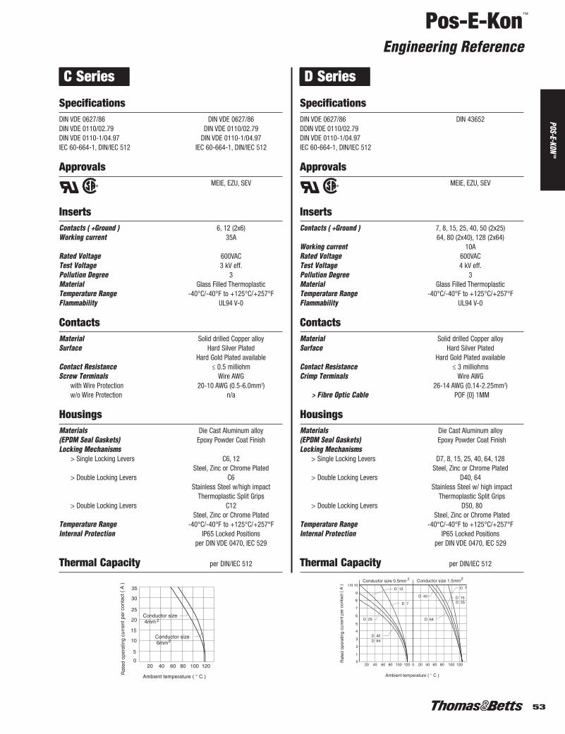
53
Pos-E-Kon™
Engineering Reference
POS-E-KONTM
SpecificationsDIN VDE 0627/86 DIN VDE 0627/86DIN VDE 0110/02.79 DIN VDE 0110/02.79DIN VDE 0110-1/04.97 DIN VDE 0110-1/04.97IEC 60-664-1, DIN/IEC 512 IEC 60-664-1, DIN/IEC 512
ApprovalsMEIE, EZU, SEV
InsertsContacts ( +Ground ) 6, 12 (2x6)Working current 35A
Rated Voltage 600VACTest Voltage 3 kV eff.Pollution Degree 3Material Glass Filled ThermoplasticTemperature Range -40°C/-40°F to +125°C/+257°FFlammability UL94 V-0
ContactsMaterial Solid drilled Copper alloySurface Hard Silver Plated
Hard Gold Plated availableContact Resistance ≤ 0.5 milliohmScrew Terminals Wire AWG
with Wire Protection 20-10 AWG (0.5-6.0mm2)w/o Wire Protection n/a
HousingsMaterials Die Cast Aluminum alloy(EPDM Seal Gaskets) Epoxy Powder Coat FinishLocking Mechanisms
> Single Locking Levers C6, 12Steel, Zinc or Chrome Plated
> Double Locking Levers C6Stainless Steel w/high impact
Thermoplastic Split Grips> Double Locking Levers C12
Steel, Zinc or Chrome PlatedTemperature Range -40°C/-40°F to +125°C/+257°FInternal Protection IP65 Locked Positions
per DIN VDE 0470, IEC 529
Thermal Capacity per DIN/IEC 512
SpecificationsDIN VDE 0627/86 DIN 43652DDIN VDE 0110/02.79DIN VDE 0110-1/04.97IEC 60-664-1, DIN/IEC 512
ApprovalsMEIE, EZU, SEV
InsertsContacts ( +Ground ) 7, 8, 15, 25, 40, 50 (2x25)
64, 80 (2x40), 128 (2x64)Working current 10ARated Voltage 600VACTest Voltage 4 kV eff.Pollution Degree 3Material Glass Filled ThermoplasticTemperature Range -40°C/-40°F to +125°C/+257°FFlammability UL94 V-0
ContactsMaterial Solid drilled Copper alloySurface Hard Silver Plated
Hard Gold Plated availableContact Resistance ≤ 3 milliohmsCrimp Terminals Wire AWG
26-14 AWG (0.14-2.25mm2)> Fibre Optic Cable POF {0} 1MM
HousingsMaterials Die Cast Aluminum alloy(EPDM Seal Gaskets) Epoxy Powder Coat FinishLocking Mechanisms
> Single Locking Levers D7, 8, 15, 25, 40, 64, 128Steel, Zinc or Chrome Plated
> Double Locking Levers D40, 64Stainless Steel w/ high impact
Thermoplastic Split Grips> Double Locking Levers D50, 80
Steel, Zinc or Chrome PlatedTemperature Range -40°C/-40°F to +125°C/+257°FInternal Protection IP65 Locked Positions
per DIN VDE 0470, IEC 529
Thermal Capacity per DIN/IEC 512
® ®
Ambient temperature ( ° C )
Rat
ed o
pera
ting
curr
ent p
er c
onta
ct (
A )
0
35
30
25
20
15
10
5
20 40 60 80 100 120
Conductor size 4mm 2
Conductor size 6mm2
Conductor size 0.5mm 2 Conductor size 1.5mm2
Ambient temperature ( ° C )
Rat
ed o
pera
ting
curr
ent p
er c
onta
ct (
A )
0
1
2
8
4
I N 10
9
5
7
6
3
20 40 60 80 100 120 0 20 40 60 80 100 120
D 64D 40
D 25
D 7
D 15
D 64
D 40
D 7
D 15D 25
C Series D Series
53-55.pdf 1 1/5/2012 2:46:53 PM1-76.pdf 53 1/6/2012 10:52:57 AM

Pos-E-Kon™
Engineering Reference
54
SpecificationsDIN VDE 0627/86DIN VDE 0110/02.79DIN VDE 0110-1/04.97IEC 60-664-1, DIN/IEC 512
ApprovalsMEIE, EZU, SEV
InsertsContacts ( +Ground ) 24, 42, 72, 108, 144 (2x72)
216 (2x10⁸)Working current 10ARated Voltage 600VACTest Voltage 2 kV eff.Pollution Degree 3Material Glass Filled ThermoplasticTemperature Range -40°C/-40°F to +125°C/+257°FFlammability UL94 V-0
ContactsMaterial Solid drilled Copper alloySurface Hard Silver Plated
Hard Gold Plated availableContact Resistance ≤ 3 milliohmsCrimp Terminals Wire AWG
26-14 AWG (0.14-2.5mm2)> Fibre Optic Cable POF {0} 1mm
HousingsMaterials Die Cast Aluminum alloy(EPDM Seal Gaskets) Epoxy Powder Coat FinishLocking Mechanisms
> Single Locking Levers DD24, 42, 72, 108, 216Steel, Zinc or Chrome Plated
> Double Locking Levers DD42, 72, 108Stainless Steel w/high impact
Thermoplastic Split Grips> Double Locking Levers DD144
Steel, Zinc or Chrome PlatedTemperature Range -40°C/-40°F to +125°C/+257°FInternal Protection IP65 Locked Positions
per DIN VDE 0470, IEC 529
Thermal Capacity
SpecificationsDIN VDE 0627/86DDIN VDE 0110/4VDE 0100/5.73-42aIEC 60-664-1, DIN/IEC 512VDE o113/1.73-10.1.3
ApprovalsMEIE, EZU, SEV
InsertsContacts ( +Ground ) 8 (16A) + 4 (80A)
16 (16A) + 8 (80A)Working current 16A and 80A dualRated Voltage 600VACTest Voltage 2 kV eff.Pollution Degree 3Material Glass Filled ThermoplasticTemperature Range -40°C/-40°F to +125°C/+257°FFlammability UL94 V-0
ContactsMaterial Solid drilled Copper alloySurface Hard Silver Plated
Hard Gold Plated availableContact Resistance ≤ 1 milliohmScrew Terminals Wire AWG
with Wire Protection (16A) 20-14 AWG (0.5-2.5mm2)(80A contacts) 18-4 AWG (1.5-16.0mm2)
HousingsMaterials Die Cast Aluminum alloy(EPDM Seal Gaskets) Epoxy Powder Coat FinishLocking Mechanisms
> Single Locking Levers K12, K24Steel, Zinc or Chrome Plated
> Double Locking Levers K12Stainless Steel w/ high impact
Thermoplastic Split Grips
Temperature Range -40°C/-40°F to +125°C/+257°FInternal Protection IP65 Locked Positions
per DIN VDE 0470, IEC 529
® ®
Conductor size 0.7mm2 Conductor size 1.5mm 2
Ambient temperature ( ° C )
Rat
ed o
pera
ting
curr
ent p
er c
onta
ct (
A )
0
10
9
8
7
6
5
4
3
2
1
20 40 60 80 100 120 0 20 40 60 80 100 120
DD 108
DD 72
DD 24
DD 42
DD 108
DD 72
DD 24
DD 42
DD Series K Series
53-55.pdf 2 1/5/2012 2:46:53 PM1-76.pdf 54 1/6/2012 10:52:57 AM

55
Pos-E-Kon™
Engineering Reference
POS-E-KONTM
SpecificationsDIN VDE 0627/86DIN VDE 0110/02.79DIN VDE 0110-1/04.97IEC 60-664-1, DIN/IEC 512
ApprovalsMEIE, EZU, SEV
InsertsContacts ( +Ground ) 3, 6, 10, 16, 20 (2x10)
26 (10+16), 32 (2x16).Working current 16A max.Rated Voltage 600VAC, Switch contacts 400 VACTest Voltage 3 kV eff.Pollution Degree 3Material Glass Filled ThermoplasticTemperature Range -40°C/-40°F to +125°C/+257°FFlammability UL94 V-0
ContactsMaterial Solid drilled Copper alloySurface Hard Silver Plated
Hard Gold Plated availableContact Resistance ≤ 1 milliohmScrew Terminals Wire AWG
with Wire Protection 20-14 AWG (0.5-2.5mm2)Crimp Terminals: 20-12 AWG (0.5-4.0mm2)
HousingsMaterials Die Cast Aluminum alloy(EPDM Seal Gaskets) Epoxy Powder Coat FinishLocking Mechanisms
> Single Locking Levers V3, 6, 10, 16, 20, 26, 32Steel, Zinc or Chrome Plated
> Double Locking Levers V3, 6, 10, 16Stainless Steel w/high impact
Thermoplastic Split Grips
Temperature Range -40°C/-40°F to +125°C/+257°FInternal Protection IP65 Locked Positions
per DIN VDE 0470, IEC 529
Thermal Capacity
SpecificationsDIN VDE 0627/86DDIN VDE 0110/02.79DIN VDE 0110-1/04.97IEC 60-664-1, DIN/IEC 512
ApprovalsMEIE, EZU, SEV
InsertsContacts ( +Ground ) 6, 10, 16, 24
Working current 16A max.Rated Voltage 600VAC, Switch contacts 400VACTest Voltage 3 kV eff.Pollution Degree 3Material Hi-Temp ThermoplasticTemperature Range -40°C/-40°F to +200°C/+392°FFlammability UL94 V-0
ContactsMaterial Solid drilled Copper alloySurface Hard Silver Plated
Hard Gold Plated availableContact Resistance ≤ 1 milliohmScrew Terminals Wire AWG
with Wire Protection 20-14 AWG (0.5-2.5mm2)
HousingsMaterials Copper-Free Die Cast Aluminum alloy(Viton® Seal Gaskets) Green Epoxy Powder CoatingLocking Mechanisms
> Single Locking Levers T6Stainless Steel, Black Coated
> Double Locking Levers T10, 16, 24Stainless Steel, with HighTemp Thermoplastic Grips
Temperature Range -40°C/-40°F to +200°C/+392°FInternal Protection IP65 Locked Positions
per DIN VDE 0470, IEC 529
Thermal Capacity per DIN/IEC 512
® ®
Conductor size 1.5mm Conductor size 2.5mm2 2
Ambient temperature ( ° C )
Rat
ed o
pera
ting
curr
ent p
er c
onta
ct (
A )
0
2
14
4
6
12
16
8
10
20 40 60 80 100 120 0 20 40 60 80 100 120
BV 3
BV 6
BV 10BV 16
BV 3
BV 6
BV 10BV 16
V Series T Series
53-55.pdf 3 1/5/2012 2:46:53 PM1-76.pdf 55 1/6/2012 10:52:57 AM
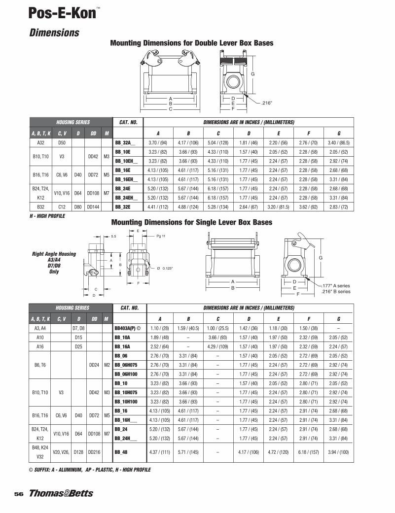
Pos-E-Kon™
Dimensions
56
BA
G
DE
F
.177" A series
.216" B series
BA
C
D
E
F
Pg 11
.Ø 0.125"
5.5
HOUSING SERIES CAT. NO. DIMENSIONS ARE IN INCHES / (MILLIMETERS)
A, B, T, K C, V D DD M A B C D E F G
A3, A4 D7, D8 BB403A(P) © 1.10 / (28) 1.59 / (40.5) 1.00 / (25.5) 1.42 / (36) 1.18 / (30) 1.50 / (38) –
A10 D15 BB_10A 1.89 / (48) – 3.66 / (93) 1.57 / (40) 1.97 / (50) 2.32 / (59) 2.05 / (52)
A16 D25 BB_16A 2.52 / (64) – 4.29 / (109) 1.57 / (40) 1.97 / (50) 2.32 / (59) 2.24 / (57)
BB_06 2.76 / (70) 3.31 / (84) – 1.57 / (40) 2.05 / (52) 2.72 / (69) 2.05 / (52)
B6, T6 DD24 M2 BB_06H075 2.76 / (70) 3.31 / (84) – 1.77 / (45) 2.24 / (57) 2.72 / (69) 2.92 / (74)
BB_06H100 2.76 / (70) 3.31 / (84) – 1.77 / (45) 2.24 / (57) 2.72 / (69) 2.92 / (74)
BB_10 3.23 / (82) 3.66 / (93) – 1.57 / (40) 2.05 / (52) 2.80 / (71) 2.05 / (52)
B10, T10 V3 DD42 M3 BB_10H075 3.23 / (82) 3.66 / (93) – 1.77 / (45) 2.24 / (57) 2.80 / (71) 2.92 / (74)
BB_10H100 3.23 / (82) 3.66 / (93) – 1.77 / (45) 2.24 / (57) 2.80 / (71) 2.92 / (74)
B16, T16 C6, V6 D40 DD72 M5BB_16 4.13 / (105) 4.61 / (117) – 1.77 / (45) 2.24 / (57) 2.91 / (74) 2.68 / (68)
BB_16H___ 4.13 / (105) 4.61 / (117) – 1.77 / (45) 2.24 / (57) 2.91 / (74) 3.31 / (84)
B24, T24, V10, V16 D64 DD108 M7
BB_24 5.20 / (132) 5.67 / (144) – 1.77 / (45) 2.24 / (57) 2.91 / (74) 2.68 / (68)
K12 BB_24H___ 5.20 / (132) 5.67 / (144) – 1.77 / (45) 2.24 / (57) 2.91 / (74) 3.31 / (84)
B48, K24V20, V26, D128 DD216 BB_48 4.37 / (111) 5.71 / (145) – 4.17 / (106) 4.72 / (120) 6.18 / (157) 3.94 / (100)
V32
© SUFFIX: A - ALUMINUM, AP - PLASTIC, H - HIGH PROFILE
Mounting Dimensions for Double Lever Box Bases
Mounting Dimensions for Single Lever Box Bases
BA
C
G
DEF
.216"
HOUSING SERIES CAT. NO. DIMENSIONS ARE IN INCHES / (MILLIMETERS)
A, B, T, K C, V D DD M A B C D E F G
A32 D50 BB_32A__ 3.70 / (94) 4.17 / (106) 5.04 / (128) 1.81 / (46) 2.20 / (56) 2.76 / (70) 3.40 / (86.5)
B10, T10 V3 DD42 M3BB_10E 3.23 / (82) 3.66 / (93) 4.33 / (110) 1.57 / (40) 2.05 / (52) 2.28 / (58) 2.05 / (52)
BB_10EH__ 3.23 / (82) 3.66 / (93) 4.33 / (110) 1.77 / (45) 2.24 / (57) 2.28 / (58) 2.92 / (74)
B16, T16 C6, V6 D40 DD72 M5BB_16E 4.13 / (105) 4.61 / (117) 5.16 / (131) 1.77 / (45) 2.24 / (57) 2.28 / (58) 2.68 / (68)
BB_16EH__ 4.13 / (105) 4.61 / (117) 5.16 / (131) 1.77 / (45) 2.24 / (57) 2.28 / (58) 3.31 / (84)
B24, T24,V10, V16 D64 DD108 M7
BB_24E 5.20 / (132) 5.67 / (144) 6.18 / (157) 1.77 / (45) 2.24 / (57) 2.28 / (58) 2.68 / (68)
K12 BB_24EH__ 5.20 / (132) 5.67 / (144) 6.18 / (157) 1.77 / (45) 2.24 / (57) 2.28 / (58) 3.31 / (84)
B32 C12 D80 DD144 BB_32E 4.41 / (112) 4.88 / (124) 5.28 / (134) 2.64 / (67) 3.20 / (81.5) 3.62 / (92) 2.83 / (72)
H - HIGH PROFILE
Right Angle HousingA3/A4D7/D8Only
56-60.pdf 1 1/5/2012 2:45:18 PM1-76.pdf 56 1/6/2012 10:52:57 AM

57
Pos-E-Kon™
Dimensions
POS-E-KONTM
HOUSING SERIES CAT. NO. DIMENSIONS ARE IN INCHES / (MILLIMETERS)
A, B, T, K C, V D DD M A B C D E F G
PB303A (P)© – 1.10 / (28) 1.34 / (34) 1.18 / (30) 1.50 / (38) 1.67 / (42.5) .95 / (24)
A3, A4 D7, D8 PB403A (P)© – 1.10 / (28) 1.38 / (35) 1.18 / (30) 1.58 / (40) 1.85 / (47) .95 / (24)
PB503A (P) – 1.10 / (28) 1.59 / (40.5) 1.00 / (25.5) 1.42 / (36) 1.18 / (30) 1.50 / (38)
A10 D15PB310A 2.76 / (70) 3.19 / (81) – .68 / (17.5) 1.20 / (30.5) 1.93 / (49) 1.02 / (26)
PB410A 2.76 / (70) 3.19 / (81) – .68 / (17.5) 1.20 / (30.5) 2.95 / (75) 1.02 / (26)
A16 D25PB316A 3.39 / (86) 3.78 / (96) – .68 / (17.5) 1.20 / (30.5) 1.93 / (49) 1.02 / (26)
PB416A 3.39 / (86) 3.78 / (96) – .68 / (17.5) 1.20 / (30.5) 2.95 / (75) 1.02 / (26)
B6, T6 DD24 M2PB306 2.76 / (70) 3.15 / (80) – 1.26 / (32) 1.69 / (43) 2.56 / (65) 1.06 / (27)
PB406 2.76 / (70) 3.15 / (80) – 1.26 / (32) 1.69 / (43) 3.54 / (90) 1.06 / (27)
B10, T10 V3 DD42 M3PB310 3.27 / (83) 3.66 / (93) – 1.26 / (32) 1.69 / (43) 2.64 / (67) 1.06 / (27)
PB410 3.27 / (83) 3.66 / (93) – 1.26 / (32) 1.69 / (43) 3.62 / (92) 1.06 / (27)
B16, T16 C6, V6 D40 DD72 M5PB316 4.06 / (103) 4.49 / (114) – 1.26 / (32) 1.69 / (43) 2.64 / (67) 1.06 / (27)
PB416 4.06 / (103) 4.49 / (114) – 1.26 / (32) 1.69 / (43) 3.62 / (92) 1.06 / (27)
B24, T24, V10, V16 D64 DD108 M7
PB324 5.12 / (130) 5.51 / (140) – 1.26 / (32) 1.69 / (43) 2.64 / (67) 1.06 / (27)
K12 PB424 5.12 / (130) 5.51 / (140) – 1.26 / (32) 1.69 / (43) 3.62 / (92) 1.06 / (27)
B48, K24V20, V26, D128 DD216
PB348 5.83 / (148) 6.50 / (165) – 2.76 / (70) 3.54 / (90) 6.18 / (157) 1.61 / (41)
V32 PB448 5.83 / (148) 6.50 / (165) – 2.76 / (70) 3.54 / (90) 6.81 / (173) 1.61 / (41)
© SUFFIX: A - ALUMINUM, P - PLASTIC
HOUSING SERIES CAT. NO. DIMENSIONS ARE IN INCHES / (MILLIMETERS)
A, B, T, K C, V D DD M A B C D E F G
A32 D50 PB132A 3.62 / (92) 4.02 / (102) 5.04 / (128) 1.65 / (28) 2.24 / (57) 2.76 / (70) 1.10 / (28)
B10, T10 V3 DD42 M3 PB110E 3.27 / (83) 3.66 / (93) 4.33 / (110) 1.26 / (32) 1.69 / (43) 2.28 / (58) 1.06 / (27)
B16, T16 C6, V6 D40 DD72 M5 PB116E 4.05 / (103) 4.49 / (114) 5.16 / (131) 1.26 / (32) 1.69 / (43) 2.28 / (58) 1.06 / (27)
B24, T24,V10, V16 D64 DD108 M7 PB124E 5.12 / (130) 5.51 / (140) 6.19 / (157) 1.26 / (32) 1.69 / (43) 2.28 / (58) 1.06 / (27)
K12
B32 C12 D80 DD144 PB132E 4.33 / (110) 4.88 / (124) 5.28 / (134) 2.56 / (65) 3.11 / (79) 3.62 / (92) 1.18 / (30)
Mounting Dimensions for Double Lever Panel Bases
Mounting Dimensions for Single Lever Panel Bases
BA
C
G
DEF
.177"
.216" B32 series
B
C
G
D
E
F
.Ø 0.125"
3
B
A
G
DE
F A series .134"B series .177"
B48 series .248"
A3/A4D7/D8Only
56-60.pdf 2 1/5/2012 2:45:18 PM1-76.pdf 57 1/6/2012 10:52:57 AM

Pos-E-Kon™
Dimensions
58
INSERT SERIES MATING DIMENSIONS ARE IN INCHES / (MILLIMETERS)
A, B, T, K C, V D DD M A B C D E
A3, A4 BOTH – 0.83 / (21) – 0.83 / (21) 0.98 / (25)
D7, D8FEMALE – 0.83 / (21) – 0.83 / (21) 1.25 / (31.8)
MALE – 0.83 / (21) – 0.83 / (21) 1.19 / (30.2)
A10 D15FEMALE 1.95 / (49.5) 2.22 / (56.5) 0.63 / (16) 1.34 / (34) 1.14 / (29)
MALE 1.95 / (49.5) 2.22 / (56.5) 0.63 / (16) 1.34 / (34) 1.26 / (32)
A16 D25FEMALE 2.60 / (66) 2.87 / (73) 0.63 / (16) 1.34 / (34) 1.14 / (29)
MALE 2.60 / (66) 2.87 / (73) 0.63 / (16) 1.34 / (34) 1.26 / (32)
A32 D50FEMALE 2.60 / (66) 2.87 / (73) 0.63 / (16) x 2 1.34 / (34) 1.14 / (29)
MALE 2.60 / (66) 2.87 / (73) 0.63 / (16) x 2 1.34 / (34) 1.26 / (32)
B6, T6 DD24 M2FEMALE 1.73 / (44) 2.01 / (51) 1.063 / (27) 1.34 / (34) 1.46 / (37)
MALE 1.73 / (44) 2.01 / (51) 1.063 / (27) 1.34 / (34) 1.38 / (35)
B10, T10 V3 DD42 M3FEMALE 2.24 / (57) 2.52 / (64) 1.063 / (27) 1.34 / (34) 1.46 / (37)
MALE 2.24 / (57) 2.52 / (64) 1.063 / (27) 1.34 / (34) 1.38 / (35)
B16, T16 C6, V6 D40 DD72 M5FEMALE 3.05 / (77.5) 3.33 / (84.5) 1.063 / (27) 1.34 / (34) 1.48 / (37.5)
MALE 3.05 / (77.5) 3.33 / (84.5) 1.063 / (27) 1.34 / (34) 1.40 / (35.5)
B24, T24,V10, V16 D64 DD108 M7
FEMALE 4.09 / (104) 4.37 / (111) 1.063 / (27) 1.34 / (34) 1.48 / (37.5)
K12 MALE 4.09 / (104) 4.37 / (111) 1.063 / (27) 1.34 / (34) 1.40 / (35.5)
B32 C12 D80 DD144FEMALE 3.05 / (77.5) 3.33 / (84.5) 1.063 / (27) x 2 1.34 / (34) 1.48 / (37.5)
MALE 3.05 / (77.5) 3.33 / (84.5) 1.063 / (27) x 2 1.34 / (34) 1.40 / (35.5)
B48, K24V20, V26,
D128 DD216FEMALE 4.09 / (104) 4.37 / (111) 1.063 / (27) x 2 1.34 / (34) 1.48 / (37.5)
V32 MALE 4.09 / (104) 4.37 / (111) 1.063 / (27) x 2 1.34 / (34) 1.40 / (35.5)
Mounting Dimensions for Screw and Crimp Terminal Inserts
B
A CD
E
56-60.pdf 3 1/5/2012 2:45:19 PM1-76.pdf 58 1/6/2012 10:52:58 AM

59
Pos-E-Kon™
Dimensions
POS-E-KONTM
Insert Screw Torque Specifications
SERIES Screw Location Unit of Measure Pozi-Drive point Std. Straight-bladeScrewdriver Screwdriver
wire termination screwNewton meters 0.4 0.9
A3 Inch ounces 57 127
A4insert grounding screw
Newton meters 0.6 0.8
Inch ounces 85 113
D7 insert grounding screwNewton meters 0.4 0.4
D8 Inch ounces 57 57
wire termination screwNewton meters 0.4 0.9
Inch ounces 57 127
insert fastening screwNewton meters 0.7 1.1
Inch ounces 99 156
insert grounding screwNewton meters 0.7 1.3
Inch ounces 99 184
insert fastening screwNewton meters 0.7 1.1
Inch ounces 99 156
insert grounding screwNewton meters 0.7 1.3
Inch ounces 99 184
wire termination screwNewton meters 0.6 0.4
Inch ounces 85 57
insert fastening screwNewton meters 0.7 1.1
Inch ounces 99 156
insert grounding screwNewton meters 1.2 1.9
Inch ounces 170 269
wire termination screwNewton meters 0.7 1.3
Inch ounces 99 184
C insert fastening screwNewton meters 0.7 1.1
Inch ounces 99 156
insert grounding screwNewton meters 2.3 2.3
Inch ounces 326 326
wire termination screwNewton meters *0.5 / 1.4 -
Inch ounces *71 / 198 -
K insert fastening screwNewton meters 0.7 -
Inch ounces 99 -
insert grounding screwNewton meters 2.3 -
Inch ounces 326 -
* 16A / 80A contacts
Insert Mounting Screws accept a blade, cross-point or Pozi-drive screwdriver heads. Specifications refer to Pozi-drive or bladed common torque only.
A10A16A32
D15D25D50
BTV
56-60.pdf 4 1/5/2012 2:45:19 PM1-76.pdf 59 1/6/2012 10:52:58 AM

Pos-E-Kon™
Dimensions
60
INSERT SERIES CAT. NO.DIMENSIONS ARE IN INCHES / (MILLIMETERS)
A B C D E F G H
FS106WAL
B6FS106WAR
1.73 / (44) 2.01 / (51) 1.03 / (26.3) 1.06 / (27) 1.34 / (34) 1.77 / (45) 2.28 / (58) 3.54 / (90)MS206WAL
MS206WAR
FS110WAL
B10FS110WAR
2.13 / (54) 2.52 / (64) 1.55 / (39.5) 1.06 / (27) 1.34 / (34) 1.77 / (45) 2.28 / (58) 3.54 / (90)MS210WAL
MS210WAR
FS116WAL
B16FS116WAR
3.05 / (77.5) 3.32 / (84.5) 2.33 / (59.3) 1.06 / (27) 1.34 / (34) 1.77 / (45) 2.28 / (58) 3.54 / (90)MS216WAL
MS216WAR
FS124WAL
B24FS124WAR
4.09 / (104) 4.37 / (111) 3.36 / (85.7) 1.06 / (27) 1.34 / (34) 1.77 / (45) 2.28 / (58) 3.54 / (90)MS224WAL
MS224WAR
D40FS340WAL
3.05 / (77.5) 3.27 / (83) 2.21 / (56) 1.06 / (27) 1.34 / (34) 3.19 / (81) 4.53 / (115) 5.12 / (130)MS440WAL
D64FS364WAL
4.09 / (104) 4.33 / (110) 3.39 / (86.3) 1.06 / (27) 1.34 / (34) 3.19 / (81) 4.53 / (115) 5.12 / (130)MS464WAL
(-WAL) - GROUND LEFT (-WAR) - GROUND RIGHT
Mounting Dimensions for Wiring Adapters
56-60.pdf 5 1/5/2012 2:45:19 PM1-76.pdf 60 1/6/2012 10:52:58 AM

61
Pos-E-Kon™
Dimensions
POS-E-KONTM
HOUSING SERIES DIMENSIONS ARE IN INCHES / (MILLIMETERS)
A, B, T, K C, V D DD M A B C D E
A3, A4 D7, D8 0.83 / (21) 1.18 / (30) 0.83 / (21) – 0.125 / (3.2)
A10 D15 1.71 / (43.5) 2.76 / (70) 0.95 / (24) 0.68 / (17.5) 0.134 / (3.4)
A16 D25 2.36 / (60) 3.39 / (86) 0.95 / (24) 0.68 / (17.5) 0.134 / (3.4)
A32 D50 2.36 / (60) 3.62 / (92) 1.89 / (48) 1.65 / (28) 0.177 / (4.5)
B6, T6 DD24 M2 1.42 / (36) 2.76 / (70) 1.38 / (35) 1.26 / (32) 0.177 / (4.5)
B10, T10 V3 DD42 M3 1.93 / (49) 3.27 / (83) 1.38 / (35) 1.26 / (32) 0.177 / (4.5)
B16, T16 C6, V6 D40 DD72 M5 2.84 / (72) 4.06 / (103) 1.38 / (35) 1.26 / (32) 0.177 / (4.5)
B24, T24,V10, V16 D64 DD108 M7 3.86 / (98) 5.12 / (130) 1.38 / (35) 1.26 / (32) 0.177 / (4.5)
K12
B32 C12 D80 DD144 2.84 / (72) 4.33 / (110) 2.80 / (71) 2.56 / (65) 0.216 / (5.5)
B48, K24V20, V26,
D128 DD216 3.86 / (98) 5.83 / (148) 2.80 / (71) 2.76 / (70) 0.248 / (6.3)V32
* Dimensions reflect dual inserts mounting.
Panel Cut Out Dimensions for Panel Bases
A3/A4D7/D8Only
61-76.pdf 1 1/5/2012 2:44:50 PM1-76.pdf 61 1/6/2012 10:52:58 AM
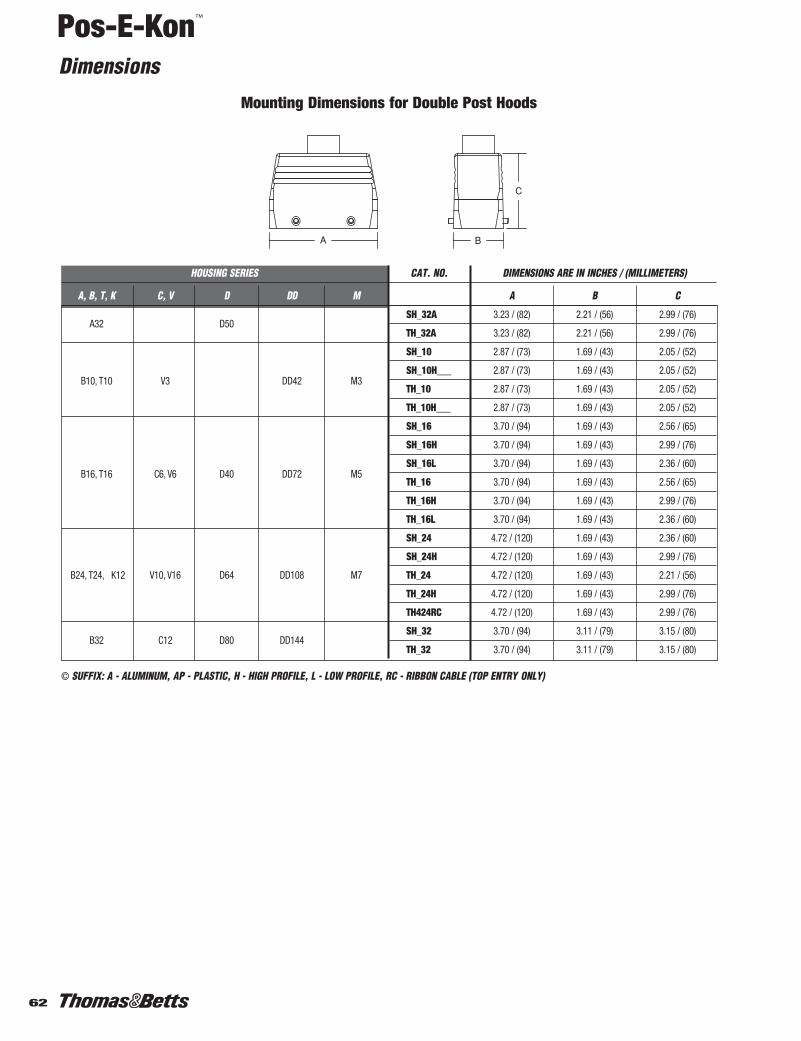
Pos-E-Kon™
Dimensions
62
HOUSING SERIES CAT. NO. DIMENSIONS ARE IN INCHES / (MILLIMETERS)
A, B, T, K C, V D DD M A B C
A32 D50SH_32A 3.23 / (82) 2.21 / (56) 2.99 / (76)
TH_32A 3.23 / (82) 2.21 / (56) 2.99 / (76)
SH_10 2.87 / (73) 1.69 / (43) 2.05 / (52)
B10, T10 V3 DD42 M3SH_10H___ 2.87 / (73) 1.69 / (43) 2.05 / (52)
TH_10 2.87 / (73) 1.69 / (43) 2.05 / (52)
TH_10H___ 2.87 / (73) 1.69 / (43) 2.05 / (52)
SH_16 3.70 / (94) 1.69 / (43) 2.56 / (65)
SH_16H 3.70 / (94) 1.69 / (43) 2.99 / (76)
B16, T16 C6, V6 D40 DD72 M5SH_16L 3.70 / (94) 1.69 / (43) 2.36 / (60)
TH_16 3.70 / (94) 1.69 / (43) 2.56 / (65)
TH_16H 3.70 / (94) 1.69 / (43) 2.99 / (76)
TH_16L 3.70 / (94) 1.69 / (43) 2.36 / (60)
SH_24 4.72 / (120) 1.69 / (43) 2.36 / (60)
SH_24H 4.72 / (120) 1.69 / (43) 2.99 / (76)
B24, T24, K12 V10, V16 D64 DD108 M7 TH_24 4.72 / (120) 1.69 / (43) 2.21 / (56)
TH_24H 4.72 / (120) 1.69 / (43) 2.99 / (76)
TH424RC 4.72 / (120) 1.69 / (43) 2.99 / (76)
B32 C12 D80 DD144SH_32 3.70 / (94) 3.11 / (79) 3.15 / (80)
TH_32 3.70 / (94) 3.11 / (79) 3.15 / (80)
© SUFFIX: A - ALUMINUM, AP - PLASTIC, H - HIGH PROFILE, L - LOW PROFILE, RC - RIBBON CABLE (TOP ENTRY ONLY)
Mounting Dimensions for Double Post Hoods
61-76.pdf 2 1/5/2012 2:44:50 PM1-76.pdf 62 1/6/2012 10:52:58 AM

63
Pos-E-Kon™
Dimensions
POS-E-KONTM
HOUSING SERIES CAT. NO. DIMENSIONS ARE IN INCHES / (MILLIMETERS)
A, B, T, K C, V D DD M A B C
A3, A4 D7, D8SH603A(P) © 1.04 / (26.5) 1.04 / (26.5) 1.89 / (48)
TH803A(P) © 1.04 / (26.5) 1.04 / (36.5) 1.89 / (48)
SH_10A 2.48 / (63) 1.42 / (36) 2.60 / (66)
A10 D15SH_10AL 2.48 / (63) 1.16 / (29.5) 2.09 / (53)
TH_10A 2.48 / (63) 1.42 / (36) 2.60 / (66)
TH_10AL 2.48 / (63) 1.16 / (29.5) 2.09 / (53)
SH_16A 3.13 / (79.5) 1.42 / (36) 2.84 / (72)
A16 D25SH_16AL 3.13 / (79.5) 1.16 / (29.5) 2.28 / (58)
TH_16A 3.13 / (79.5) 1.42 / (36) 2.84 / (72)
TH_16AL 3.13 / (79.5) 1.16 / (29.5) 2.28 / (58)
SH_606 2.36 / (60) 1.69 / (43) 1.69 / (43)
B6, T6 DD24 M2SH_606Hxxx 2.36 / (60) 1.69 / (43) 2.84 / (72)
TH_806 2.36 / (60) 1.69 / (43) 1.69 / (43)
TH_806Hxxx 2.36 / (60) 1.69 / (43) 2.84 / (72)
SH_610 2.87 / (73) 1.69 / (43) 2.05 / (52)
B10, T10 V3 DD42 M3SH_610Hxxx 2.87 / (73) 1.69 / (43) 2.84 / (72)
TH_810 2.87 / (73) 1.69 / (43) 2.05 / (52)
TH_810Hxxx 2.87 / (73) 1.69 / (43) 2.84 / (72)
SH_616 3.70 / (94) 1.69 / (43) 2.56 / (65)
SH_616H 3.70 / (94) 1.69 / (43) 2.99 / (76)
SH_616L 3.70 / (94) 1.69 / (43) 2.36 / (60)
B16, T16 C6, V6 D40 DD72 M5 TH_816 3.70 / (94) 1.69 / (43) 2.56 / (65)
TH_816H 3.70 / (94) 1.69 / (43) 2.99 / (76)
TH_816L 3.70 / (94) 1.69 / (43) 2.36 / (60)
TH816RC 3.70 / (94) 1.69 / (43) 2.99 / (76)
SH_624 4.72 / (120) 1.69 / (43) 2.99 / (76)
B24, T24 V10, V16 D64 DD108 M7SH_624L 4.72 / (120) 1.69 / (43) 2.36 / (60)
TH_824 4.72 / (120) 1.69 / (43) 2.99 / (76)K12
TH824L 4.72 / (120) 1.69 / (43) 2.36 / (60)
TH624RC 4.72 / (120) 1.69 / (43) 2.99 / (76)
B48, K24V20, V26,
D128 DD216SH_48 5.16 / (131.5) 3.50 / (89) 3.78 / (96)
V32 TH_48 5.16 / (131.5) 3.50 / (89) 3.78 / (96)
© SUFFIX: AP - PLASTIC, H - HIGH PROFILE, L - LOW PROFILE, RC - RIBBON CABLE (TOP ENTRY ONLY)
Mounting Dimensions for Single Post Hoods
61-76.pdf 3 1/5/2012 2:44:50 PM1-76.pdf 63 1/6/2012 10:52:58 AM

Pos-E-Kon™
Dimensions
64
HOUSING SERIES CAT. NO. DIMENSIONS ARE IN INCHES / (MILLIMETERS)
A, B, T, K C, V D DD M A B C D E
B10, T10 V3 DD42 M3CH610E 2.87 / (73) 4.33 / (110) 1.69 / (43) 2.28 / (58) 2.02 / (51.5)
CH610EHxxx 2.87 / (73) 4.33 / (110) 1.69 / (43) 2.28 / (58) 2.87 / (73)
CH_16E 3.70 / (94) 5.16 / (131) 1.69 / (43) 2.28 / (58) 2.72 / (69)
B16, T16 C6, V6 D40 DD72 M5 CH_16EH 3.70 / (94) 5.16 / (131) 1.69 / (43) 2.28 / (58) 3.15 / (80)
CH616ERC 3.70 / (94) 5.16 / (131) 1.69 / (43) 2.28 / (58) 3.15 / (80)
B24, T24,V10, V16 D64 DD108 M7
CH_24E 4.72 / (120) 6.18 / (157) 1.69 / (43) 2.28 / (58) 3.15 / (80)
K12 CH624ERC 4.72 / (120) 6.18 / (157) 1.69 / (43) 2.28 / (58) 3.15 / (80)
B32 C12 D80 DD144 CH_32E 3.70 / (94) 5.28 / (134) 3.11 / (79) 3.62 / (92) 3.23 / (82)
H - HIGH PROFILE, RC - RIBBON CABLE (TOP ENTRY)
Mounting Dimensions for Double Lever Coupler Hoods
Mounting Dimensions for Single Lever Coupler Hoods
HOUSING SERIES CAT. NO. DIMENSIONS ARE IN INCHES / (MILLIMETERS)
A, B, T, K C, V D DD M A B C D E
A3, A4 D7, D8 CH803A(P) © 1.34 / (34) – 1.04 / (26.5) 1.43 / (36.5) 2.02 / (51.5)
A10 D15 CH810A 2.48 / (63) – 1.16 / (29.5) 1.92 (49) 1.89 / (48)
A16 D25 CH816A 3.13 / (79.5) – 1.16 / (29.5) 1.92 (49) 2.09 / (53)
B6, T6 DD24 M2CH806 2.36 / (60) – 1.69 / (43) 2.56 / (65) 2.02 / (51.5)
CH806Hxxx 2.36 / (60) – 1.69 / (43) 2.56 / (65) 2.87 / (73)
B10, T10 V3 DD42 M3CH810 2.87 / (73) – 1.69 / (43) 2.64 / (67) 2.02 / (51.5)
CH810Hxxx 2.87 / (73) – 1.69 / (43) 2.64 / (67) 2.87 / (73)
CH_16 3.70 / (94) – 1.69 / (43) 2.64 / (67) 2.72 / (69)
B16, T16 C6, V6 D40 DD72 M5 CH_16H 3.70 / (94) – 1.69 / (43) 2.64 / (67) 3.15 / (80)
CH616RC 3.70 / (94) – 1.69 / (43) 2.64 / (67) 3.15 / (80)
B24, T24,V10, V16 D64 DD108 M7
CH_24 4.72 / (120) – 1.69 / (43) 2.64 / (67) 3.15 / (80)
K12 CH824RC 4.72 / (120) – 1.69 / (43) 2.64 / (67) 3.15 / (80)
© SUFFIX: A - ALUMINUM, AP - PLASTIC, H - HIGH PROFILE, L - LOW PROFILE, RC - RIBBON CABLE (TOP ENTRY ONLY)
A3/A4D7/D8Only
61-76.pdf 4 1/5/2012 2:44:50 PM1-76.pdf 64 1/6/2012 10:52:58 AM
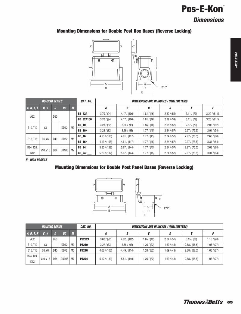
65
Pos-E-Kon™
Dimensions
POS-E-KONTM
HOUSING SERIES CAT. NO. DIMENSIONS ARE IN INCHES / (MILLIMETERS)
A, B, T, K C, V D DD M A B C D E F
A32 D50BB_32A 3.70 / (94) 4.17 / (106) 1.81 / (46) 2.32 / (59) 3.11 / (79) 3.20 / (81.5)
BB_32A100 3.70 / (94) 4.17 / (106) 1.81 / (46) 2.32 / (59) 3.11 / (79) 3.20 / (81.5)
B10, T10 V3 DD42 M3BB_10 3.23 / (82) 3.66 / (93) 1.56 / (40) 2.05 / (52) 2.87 / (73) 2.05 / (52)
BB_10H___ 3.23 / (82) 3.66 / (93) 1.77 / (45) 2.24 / (57) 2.97 / (75.5) 2.91 / (74)
B16, T16 C6, V6 D40 DD72 M5BB_16 4.13 / (105) 4.61 / (117) 1.77 / (45) 2.24 / (57) 2.97 / (75.5) 2.68 / (68)
BB_16H___ 4.13 / (105) 4.61 / (117) 1.77 / (45) 2.24 / (57) 2.97 / (75.5) 3.31 / (84)
B24, T24,V10, V16 D64 DD108 M7
BB_24 5.20 / (132) 5.67 / (144) 1.77 / (45) 2.24 / (57) 2.97 / (75.5) 2.68 / (68)
K12 BB_24H___ 5.20 / (132) 5.67 / (144) 1.77 / (45) 2.24 / (57) 2.97 / (75.5) 3.31 / (84)
H - HIGH PROFILE
Mounting Dimensions for Double Post Box Bases (Reverse Locking)
HOUSING SERIES CAT. NO. DIMENSIONS ARE IN INCHES / (MILLIMETERS)
A, B, T, K C, V D DD M A B C D E F
A32 D50 PB232A 3.62 / (92) 4.02 / (102) 1.65 / (42) 2.24 / (57) 3.15 / (80) 1.10 / (28)
B10, T10 V3 DD42 M3 PB210 3.27 / (83) 3.66 / (93) 1.26 / (32) 1.69 / (43) 2.68 / (68.5) 1.06 / (27)
B16, T16 C6, V6 D40 DD72 M5 PB216 4.06 / (103) 4.49 / (114) 1.26 / (32) 1.69 / (43) 2.68 / (68.5) 1.06 / (27)
B24, T24,V10, V16 D64 DD108 M7 PB224 5.12 / (130) 5.51 / (140) 1.26 / (32) 1.69 / (43) 2.68 / (68.5) 1.06 / (27)
K12
Mounting Dimensions for Double Post Panel Bases (Reverse Locking)
61-76.pdf 5 1/5/2012 2:44:51 PM1-76.pdf 65 1/6/2012 10:52:58 AM

Pos-E-Kon™
Dimensions
66
HOUSING SERIES CAT. NO. DIMENSIONS ARE IN INCHES / (MILLIMETERS)
A, B, T, K C, V D DD M A B C D E
A32 D50 LH_32A 3.23 / (82) 5.04 / (128) 2.21 / (56) 2.76 / (70) 2.99 / (76)
B10, T10 V3 DD42 M3LH_10E 2.87 / (73) 4.33 / (110) 1.69 / (43) 2.28 / (58) 1.89 / (48)
LH_10EH___ 2.87 / (73) 4.33 / (110) 1.69 / (43) 2.28 / (58) 2.84 / (72)
B16, T16 C6, V6 D40 DD72 M5LH_16E 3.70 / (94) 5.16 / (131) 1.69 / (43) 2.28 / (58) 2.56 / (65)
LH_16EH 3.70 / (94) 5.16 / (131) 1.69 / (43) 2.28 / (58) 2.99 / (76)
B24, T24,V10, V16 D64 DD108 M7 LH_24E 4.72 / (120) 6.18 / (157) 1.69 / (43) 2.28 / (58) 2.99 / (76)
K12
H - HIGH PROFILE
Mounting Dimensions for Double Lever Hoods (Reverse Locking)
Dust Covers for Housings
HOUSING SERIES FOR SINGLE LEVER FOR DOUBLE LEVER FOR SINGLE FOR DOUBLEA, B, T, K C, V D DD M HOUSINGS HOUSINGS POST HOUSINGS POST HOUSINGS
A3, A4 D7, D8 DCL103A-1
A10 D15 DCL110A-1 DCS110A-1
A16 D25 DCL116A-1 DCS116A-1
A32 D50 DCL232A-1/DCL432A-1* DCS232A-1
B6, T6 q DD24 M2 DCL106B-1
B10, T10 q V3 DD42 M3 DCL110B-1 DCL210B-1/DCL410B-1*
B16, T16 q C6, V6 D40 DD72 M5 DCL116B-1 DCL216B-1/DCL416B-1*
B24, T24 q, K12 V10, V16 D64 DD108 M7 DCL124B-1 DCL224B-1/DCL424B-1*
* COMES WITH GASKET FOR NON-GASKETED HOODS W/LEVERSq DUST COVERS TESTED ONLY TO 125°C
61-76.pdf 6 1/5/2012 2:44:51 PM1-76.pdf 66 1/6/2012 10:52:58 AM

67
Pos-E-Kon™
Dimensions
POS-E-KONTM
HOUSING SERIES SUB-MINIATURE CONNECTOR
A, B, T, K C, V D DD M DB9 DB15 DB25 DB37 DB50
A3, A4 D7, D8 NO ADAPTER FOR THIS SERIES
A10 D15 AP681A10 AP677A10 AP678A10
A16 D25 AP682A16 AP683A16
A32 D50
B6, T6 DD24 M2AP796B6 AP797B6
AP802B6* AP803B6*
B10, T10 V3 DD42 M3AP798B10
AP804B10*
B16, T16 C6, V6 D40 DD72 M5AP799B16 AP800B16
AP805B16* AP806B16*
B24, T24, K12 V10, V16 D64 DD108 M7 N/A
B32 C12 D80 DD144 N/A
B48, K24 V20, V26, V32 D128 DD216 N/A
* DUAL MOUNTING
Sub-Miniature Adapter Plate Selection Guide
Sub-Miniature Adapter Plate Mounting Dimensions
BA
D C
DIMENSIONS ARE IN INCHES / (MILLIMETERS)
CAT. NO. A B C D
AP677A10 2.22 / (56.5) 0.91 / (23) 1.95 / (49.5) 0.63 / (16)
AP678A10 2.22 / (56.5) 0.91 / (23) 1.95 / (49.5) 0.63 / (16)
AP681A10 2.22 / (56.5) 0.91 / (23) 1.95 / (49.5) 0.63 / (16)
AP682A16 2.87 / (73) 0.91 / (23) 2.60 / (66) 0.63 / (16)
AP683A16 2.87 / (73) 0.91 / (23) 2.60 / (66) 0.63 / (16)
AP796B6 2.03 / (51.5) 1.73 / (44) 1.36 / (34.5) 1.06 / (27)
AP797B6 2.03 / (51.5) 1.73 / (44) 1.36 / (34.5) 1.06 / (27)
AP798B10 2.54 / (64.5) 2.24 / (57) 1.36 / (34.5) 1.06 / (27)
AP799B16 3.35 / (85) 3.05 / (77.5) 1.36 / (34.5) 1.06 / (27)
AP800B16 3.35 / (85) 3.05 / (77.5) 1.36 / (34.5) 1.06 / (27)
AP802B6* 2.03 / (51.5) 1.73 / (44) 1.36 / (34.5) 1.06 / (27)
AP803B6* 2.03 / (51.5) 1.73 / (44) 1.36 / (34.5) 1.06 / (27)
AP804B10* 2.54 / (64.5) 2.24 / (57) 1.36 / (34.5) 1.06 / (27)
AP805B16* 3.35 / (85) 3.05 / (77.5) 1.36 / (34.5) 1.06 / (27)
AP806B16* 3.35 / (85) 3.05 / (77.5) 1.36 / (34.5) 1.06 / (27)
* DUAL MOUNTING
BA
D C * DUAL MOUNTING
61-76.pdf 7 1/5/2012 2:44:51 PM1-76.pdf 67 1/6/2012 10:52:59 AM

Pos-E-Kon™
Dimensions
68
Size Adapter Plate: Selection Guide for Panel Installation
A
C
D B
ADAPTER SIZE CAT. NO.DIMENSIONS ARE IN INCHES / (MILLIMETERS)
A B C D
B24 to B6 AP650B6 5.90 / (150) 2.05 / (52) 5.12 / (130) 1.26 / (32)
B24 to B10 AP651B10 5.90 / (150) 2.05 / (52) 5.12 / (130) 1.26 / (32)
B24 to B16 AP652B16 5.90 / (150) 2.05 / (52) 5.12 / (130) 1.26 / (32)
NOTE: ADAPTER PLATES ARE FORUSE WITH PANEL BASES IN SERIESB24, D64, DD108, M7, V10, AND
V16
Cover Plate Selection Guide
A
B
D C
HOUSING SERIES CAT. NO. DIMENSIONS ARE IN INCHES / (MILLIMETERS)
A, B, T, K C, V D DD M A B C D
A3, A4 D7, D8
A10 D15 CP684A10 3.43 / (87) 2.76 / (70) 1.57 / (40) 0.69 / (17.5)
A16 D25 CP685A16 3.94 / (100) 3.39 / (86) 1.77 / (45) 0.69 / (17.5)
B6, T6 DD24 M2 CP638B6 3.39 / (86) 2.76 / (70) 2.05 / (52) 1.26 / (32)
B10, T10 V3 DD42 M3 CP639B10 4.02 / (102) 3.27 / (83) 2.05 / (52) 1.26 / (32)
B16, T16 C6, V6 D40 DD72 M5 CP640B16 4.84 / (123) 4.06 / (103) 2.05 / (52) 1.26 / (32)
B24, T24, K12 V10, V16 D64 DD108 M7 CP641B24 5.91 / (150) 5.12 / (130) 2.05 / (52) 1.26 / (32)
NOTE: COVER PLATES ARE FOR USE ON PANEL BASES ONLY
Gaskets
HOUSING SERIES CAT. NOS.
PANEL BASE, *MOLDED EDGE A, B, T, K C, V D DD M FLAT CONTOUR
A3, A4 D7, D8 A04XFGP A04XMEC
A10 D15 A10VFGP A10XMEC
A16 D25 A16XFGP A16XMEC
A32 D50 A32XFGP A32XMEC
B6, T6 q DD24 M2 B6XFGP B6XMEC
B10, T10 q V3 DD42 M3 B10XFGP B10XMEC
B16, T16 q V6, C6 D40 DD72 M5 B16XFGP B16XMEC
B24, T24 q, K12 V10, V16 D64 DD108 M7 B24XFGP B24XMEC
B32 C12 D80 DD144 B32XFGP B32XMEC
B48, K24 V20, V26, V32 D128 DD216 B48XFGP B48XMEC
* INSTALL WITH SILICONE SEALANT/ADHESIVE FOR INDUSTRIAL USE.q FOR T SERIES 200°C APPLICATIONS, CHANGE PREFIX IN CATALOGUE NUMBER FROM B TO T. EX: “T16XFGP” FOR PANEL BASE GASKETS.
61-76.pdf 8 1/5/2012 2:44:51 PM1-76.pdf 68 1/6/2012 10:52:59 AM

69
Pos-E-Kon™
Multiple Installation Coding Options
POS-E-KONTM
Guide Sleeve
Coding Pins, Guide Pins and Sleeves can be used in all series housings, with all inserts.
PC600
Coding Pin
F M
1
F M
2
F M
3
F M
4
F M
5
F M
6
Coding possibilities for single insert series
F F
1 2 3 4 5 6
M M F F M M F F M M F F M M F F M M F F M M
Coding possibilities for double insert series
MG601
Guide Pin
FG602
1
F M
2
F M
3
F M
4
F M
6
F M
5
F M
7
F M
Coding possibilities for single insert series
F F
1 2 3 4 5 6
M M F F M M F F M M F F M M F F M M F F M M
Coding possibilities for double insert series
Coding Pins: Used as key pins in multiple “same size or series”insert/hood installations. Patterns show examples of key pin codingpins installed.
Guide Pins and Sleeves: Perform same func-tion as coding pins and/or aid hi-densityinsert mating as well.
– Male Guide Pins or Coding Pins
– Female Guide Sleeves
– Mounting Screw
61-76.pdf 9 1/5/2012 2:44:51 PM1-76.pdf 69 1/6/2012 10:52:59 AM

Pos-E-Kon™
Cable and Conduit Entry
70
Metric Pg-to-NPT Thread AdaptersCat. No. NPT Thread (mating) Thread (at housing)
PG11-38 c" Pg11PG16-50 d" Pg16PG21-75 f" Pg21PG29-100 1" Pg29PG29-125 1b" Pg29PG36-125 1b" Pg36PG36-150 1d" Pg36PG42-200 2" Pg42
Metric Two-Screw Clamp ConnectorsCable O.D. (in.)
Cat. No. Min. Max. Thread (at housing)
CC11-38 0.400 0.470 Pg11CC11-38P* 0.250 0.325 Pg11CC135-50 0.400 0.535 Pg13.5CC16-50 0.455 0.625 Pg16CC21-75 0.513 0.815 Pg21CC29-100 0.800 0.175 Pg291CC36-125 1.050 0.450 Pg361CC42-150 1.500 0.800 Pg421
* Plastic
Metric Cord Grip ConnectorsCord O.D. (in.)
Cat. No. Min. Max. Thread (at housing)
CG11-38 0.200 0.470 Pg11CG11-38P* 0.325 0.340 Pg11CG135-50 0.285 0.545 Pg13.5CG16-50 0.285 0.625 Pg16CG21-75 0.395 0.790 Pg21CG29-100 0.780 0.060 Pg291CG36-125 0.960 0.375 Pg361CG42-150 1.630 0.650 Pg421
* Plastic
Conduit Entry Blind PlugCat. No. Thread (at housing)
CXP722 Pg13.5CXP723 Pg16CXP724 Pg21CXP725 Pg29CXP726 Pg36CXP727 Pg42
Supplied standard with all hoodsand bases. Special sizes/hoodcombinations available.
Style may vary depending on size.
Standard European style – can bespecified/supplied with hoods andbases.
61-76.pdf 10 1/5/2012 2:44:51 PM1-76.pdf 70 1/6/2012 10:52:59 AM

71
Pos-E-Kon™
Cable and Conduit Entry
POS-E-KONTM
Ribbon Cable Entry Strain Relief Kit for Hoods
Cat. No. Description Entry
RHK 601 One cable entry 40 x 5mmRHK 602 Two cable entry 40 x 10mmRHK 603 Three cable entry 40 x 15mm
Ribbon Cable Entry Strain Relief Kit for BasesCat. No. Hub Size
RBK 708 Pg 16RBK 709 Pg 21RBK 710 Pg 29RBK 711 Pg 36RBK 712 Pg 42
Other sizes available as specials.
Nonmetallic Cord Grip FittingsNPT Threads Cord Range
Cat. No. ln. mm Thread Size (in.)
CC-NPT38-G 0.197-0.394 5-10 cCC-NPT12-G 0.394-0.551 10-14 dCC-NPT34-G 0.512-0.709 13-18 fCC-NPT1-G 0.709-0.984 18-25 1
Pg Threads Cord Range
Cat. No. ln. mm Thread Size
CC-PG11-G 0.197-0.394 5-10 11CC-PG135-G 0.336-0.473 6-12 13.5CC-PG16-G 0.394-0.551 10-14 16CC-PG21-G 0.512-0.709 13-18 21CC-PG29-G 0.709-0.984 18-25 29CC-PG36-G 0.867-1.26 22-32 36
EM—Shielding Fitting (For externally shielded cable)Cat. No. Hub Size
GEM672 Pg 13.5GEM673 Pg 16GEM674 Pg 21GEM675 Pg 29
61-76.pdf 11 1/5/2012 2:44:51 PM1-76.pdf 71 1/6/2012 10:52:59 AM

Pos-E-Kon™
Connection with Fiber Optic (POF) Cable
72
Instructions1. Before crimping the 1,0 mm POF* cable
to the optic contact, the end of the fiberhas to be polished. Stick end of POF* cableinto polishing tool and grind on a plane sur-face (e.g. glass plate). Wipe off anyresidues after polishing. The best opticaldamping values are achieved with wet-pol-ishing-procedure.
polishing tool
4. Optical Fiber crimpingAdjust the positioning sleeve into the corre-sponding inlet of the crimping tool with thestop screw at 1,45 mm (if necessary checkwith gauge pin, diameter 1,45 mm, withclosed crimping tool).Insert the optic contact, together with thePOF* cable, through the crimp opening of thecrimping tool into the positioning sleeve.By pressure on the contact, the fiber insidewill be locked into the right position for crimp-ing. Continue pressure until the release mech-anism is heard.
*POF = Polymer Optical Fiber
2. Strip the 1,0 mm POF* cable as follows: minimum 14 mm for D sleeve contacts andminimum 19 mm for D pin contacts.
for sleeve contacts min. 14 mmfor pin contacts min. 19 mm
sleeve contact about 1,0 mm
pin contact about 1,0 mm
crimping area pin contact
positioning sleevefibre optic contact
3. Insert stripped POF* cable in sleeve or pincontact until stop. The optical fiber shouldthen stick about 1 mm out of the contact.
crimping area sleeve contact
61-76.pdf 12 1/5/2012 2:44:52 PM1-76.pdf 72 1/6/2012 10:52:59 AM

73
Pos-E-Kon™
Fiber Optic Connection Components
POS-E-KONTM
For use in M10 Series Inserts
Crimp Tool CT610
4 Indents
Positioning sleeve FPS701
Glass Fiber Cable
Stripper 1,0 mm FST700
Polishing Tool FPT702
Polishing Sheet FSS7031000 Grain
Male Pin Female Sleeve
61-76.pdf 13 1/5/2012 2:44:52 PM1-76.pdf 73 1/6/2012 10:52:59 AM