Embed Size (px)
Citation preview
International Journal of Advances in Engineering & Technology, May 2012.
©IJAET ISSN: 2231-1963
253 Vol. 3, Issue 2, pp. 253-264
POSITION ANALYSIS BASED APPROACH FOR TRAJECTORY
TRACKING CONTROL OF SCORBOT-ER-V PLUS ROBOT
MANIPULATOR
Himanshu Chaudhary1, Rajendra Prasad
2 and N. Sukavanum
3
1&2Department of Electrical Engineering, IIT Roorkee, India
3Department of Mathematics, IIT Roorkee, India
ABSTRACT
One of the most common requirements in robotics is to move the end-effector smoothly from initiallocation to
goallocation. In this paper, two approaches to generating such trajectories: straight lines in joint space and
straight lines in Cartesian space have been discussed. These are known respectively as jointspace and
Cartesianspacetracking. Two user defined algorithms are developed for Joint space as well as Cartesian space
trajectory tracking. The algorithm has been tested in simulation yielding fair results, which have also been
compared with each otherto check the accuracy and results of both.
KEYWORDS: Dof, Matlab, Trajectory Planning, Smoothness, Singularities Avoidance, Cartesian Path
Generation,
I. INTRODUCTION
Position analysis based solutionsare veryvitalwhen one wants to performmodelling of robotic arm. It
turns out to be a difficult task to find the solution through inverse kinematics with increase in Degree
of Freedom (DOF) of robot. The conventional methods used for calculating inverse kinematics of any
robot manipulator are: geometric [1-2], algebraic [3-5] and iterative [6] approaches. While algebraic
methods cannot promise closed form solutions. Geometric methods must be able to produce closed
form solutions for the first three joints of the manipulator geometrically. The iterative methods on the
other hand approach only to a single solution and that solution also depends on the starting point.To
solve the inverse kinematics problem for three different cases of threeDOF manipulator in three
dimensionalspaces,a solution was proposed in [7]usingfeed-forward neural networks.This introduces
the fault-tolerant and highspeed advantages of neural networks to the inverse kinematics problem.A
threelayer partially recurrent neural network was proposed by [8]for trajectory planning and to solve
the inverse kinematics as well as the inverse dynamics problems in a single processing stage for the
PUMA 560 manipulator. Hierarchical control technique based on the establishment of a non-linear
mapping between Cartesian and joint coordinates using fuzzy logic in order to direct each individual
jointwas proposed in[9],for controlling a robotic manipulator. Commercial Microbot with 3-DOF was
utilized to evaluate the proposed method. A novel modular neural network systemto overcome the
discontinuity of the inverse kinematics function was proposed in [10] that consist of a number of
expert neural networks. Neural network based three-joint robotic manipulator simulation software was
developed in [11] for inverse kinematics solution of a robotic manipulator. Then a designed neural
network was used to solve the inverse kinematics problem. An Artificial Neural Network (ANN)
based on Bees Algorithm using backpropagation algorithm was applied in [12] to solve inverse
kinematics problems of industrial robot manipulator. That in turns used to train multi-layer perceptron
neural networks in[13]to model the inverse kinematics of an articulated robot manipulator arm. An

International Journal of Advances in Engineering & Technology, May 2012.
©IJAET ISSN: 2231-1963
254 Vol. 3, Issue 2, pp. 253-264
Artificial Neural Network (ANN) based approach for fast inverse kinematics computation and
effective geometrically bounded singularities prevention of redundant manipulators was presented in
[14]. First some bounded geometrical concepts were used to establish some characterizing matrices, to
get a simple performance index, and a null space vector for singularities avoidance/prevention and
secure way generation. Then inverse kinematics based on above assumptions was computed using a
properly trained ANN. A reliability neural network based inverse kinematics solution approach was
presented in [15], which in turns applied to a 6-DOF robot manipulator. The structure of the proposed
method was based on Elman network using three networks designed parallel to minimize the error of
the whole system. An adaptive learning strategy using an artificial neural network (ANN) to control
the motion of a 6-DOF manipulator robot by overcoming the inverse kinematics problem was
proposed in[16] which mainly included singularities and uncertainties in arm configurations. The
proposed control technique didnot require any prior knowledge of the kinematics model of the system
being controlled. An Adaptive NeuroFuzzy Inference System (ANFIS) method based on the Artificial
Neural Network (ANN) was applied in [17] to design an Inverse Kinematic based controller for the
inverse kinematical control of SCORBOT-ER-V Plus. The proposed ANFIS controller combined the
advantages of a fuzzy controller as well as the quick response and adaptability nature of an ANN.
Computer Simulation was carried out to demonstrate the accuracy of the proposed controller to
generate an appropriate joint angle for reaching desired Cartesian state, without any error.
A path tracking algorithm to compensate for path deviation due to torque limits was proposed by [18]
which in turns used a disturbance observer to obtain a Simple Equivalent Robot Dynamic (SERD)
model to modify the desired acceleration of the nominal trajectory in Cartesian space.A technique
based on Continuous Genetic Algorithms (CGA) to solve the path generation problem for robot
manipulators was presented in [19]. The inverse kinematics problem was formulated as an
optimization problem based on the concept of the minimization of the accumulative path deviation
and is then solved by the presented technique.A unified approach to optimal pose trajectory planning
for robot manipulators in Cartesian space through a genetic algorithm (GA) enhanced optimization of
the pose ruled surface was presented in[20]. The optimization model is established based on
functional analysis and dynamics planning, and instantiated by using highorder parametric space
curves as position and orientation trajectories. [21] discussed the problem of minimum cost trajectory
planning for robotic manipulators, in which the generic optimal control problem was transformed into
a non-linear constrained optimization problem which is treated then by the Sequential Quadratic
Programming (SQP) method. Simulated Annealing (SA) technique was applied to the problem of
robot path planning in [22]. Three situations were considered: the path is represented as a polyline; as
a BAzier curve; and, as a spline interpolated curve. In order to ensure that the resulting trajectory is
smooth enough, an objective function containing a term proportional to the integral of the squared
jerk (defined as the derivative of the acceleration) along the trajectory was considered in [23]. Then
another term proportional to the total execution time was added to the expression of the objective
function. Fifthorder B-splines were then used to compose the overall trajectory. The path planning
problem with general end-effector constraints for robot manipulators was addressed in [24]. Two
approaches were proposed. The first approach was the Adapted Randomized Gradient Descent
(ARGD) method, and the second approach was radically different as it worked in both task space and
Cartesian space in comparison with first which searches purely in Cartesian space. A planning mode
of trajectory motion for seriallink manipulators with higherdegree polynomials application was
discussed in [25]. The linear acceleration profiles of end-effector, for each coordinate, were planned
as the polynomials of degrees 9, 7 and 5. This approach to polynomial form structure necessitates the
determination of only one polynomial coefficient, irrespective of its order. Method based on trajectory
planning to avoid the detachment of joint elements of a manipulator with clearances was offered in
[26]. An improved detachment criterion for the revolute and spherical joints was proposed. An
analysis based on cubic splines or fifthorder B-splines trajectory of an algorithm for optimal trajectory
planning of robot manipulators was presented in [27]. The objective function to be minimized is a
weighted sum of the integral squared jerk and the execution time. The proposed technique allowed
setting constraints on the robot motion, expressed as upper bounds on the absolute values of velocity,
acceleration and jerk. A robust and fast procedure that could be used to identify the joint stiffness
values of any sixrevolute serial robots was presented in [28]. The proposed method aimed to evaluate
joint stiffness values by considering both translational and rotational displacements of the robot end-
International Journal of Advances in Engineering & Technology, May 2012.
©IJAET ISSN: 2231-1963
255 Vol. 3, Issue 2, pp. 253-264
effector for a given applied wrench (force and torque).An experimental investigation on a robot
manipulator, using neural network for analyzing the vibration condition on joints was done in [29].
Firstly, robot manipulator’s joints were tested with prescribed of trajectory end-effectors for the
different joints speeds. Furthermore, noise and vibration of each joint were measured. And then, the
related parameters were tested with neural network predictor to predict servicing period.
Whileexposing some of the issues associated withshortcuts-like post-processing algorithms, the [30]
addressed the optimization of paths generated using an iterative user defined randomized
algorithms.[31] proposed a new method for inverse kinematics for hyper-redundant manipulators, to
plan the path of the end-effector. The inverse kinematics was computed for a given smooth
pathconsisting of points close enough to each other.[32] proposed a new approach for solving the
problem of obstacle avoidance during manipulation tasks performed by redundant manipulators,
which solution is based on a double neural network that uses Q-learning reinforcement technique. Q-
learning has been applied in robotics for attaining obstacle free navigation or computing path planning
problems.
In this paper, we present a simulation based solution for trajectory tracking of SCORBOT- ER-V
PLUS robot manipulator. It can efficiently solve practical and real size problems. Robot positional
analysis singularities and workspace constraints were considered in developing the model. The
method was tested on a SCORBOT-ER-V PLUS robot in the Control System and Robotics
Laboratory at IIT Roorkee.
This paper is organized into four sections. In the next section, the Positional analysis (Forward as well
as inverse kinematics) of SCORBOT-ER-V Plus has been briefed with the help of DH algorithm as
well as conventional techniques methods. The trajectory planning based on the positional analysis is
introduced in section2. It also explains about the two approaches used for trajectory tracking with the
help of flow charts. Simulation results are discussed in section3. Section 4 gives concluding remarks.
II. POSITION ANALYSIS OF SCORBOT-ER-V PLUS [17]
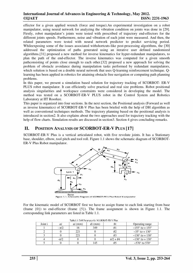
SCORBOT-ER-V Plus is a vertical articulated robot, with five revolute joints. It has a Stationary
base, shoulder, elbow, tool pitch and tool roll. Figure 1.1 shows the schematic diagram of SCORBOT-
ER-V Plus Robot manipulator.
For the kinematic model of SCORBOT first we have to assign frame to each link starting from base
(frame {0}) to end-effector (frame {5}). The frame assignment is shown in Figure 1.1. The
corresponding link parameters are listed in Table 1.1.
Joint i �� �� (��) �� (��) �� Operating range
1 - �/2 16 349 �1 −155° � + 155°
2 0 221 0 �2 −35° � + 130°
3 0 221 0 �3 −130° � + 130°
4 -�/2 0 0 �/2 + �4 −130° � + 130°
5 0 0 145 �5 −570° � 570°
International Journal of Advances in Engineering & Technology, May 2012.
©IJAET ISSN: 2231-1963
256 Vol. 3, Issue 2, pp. 253-264
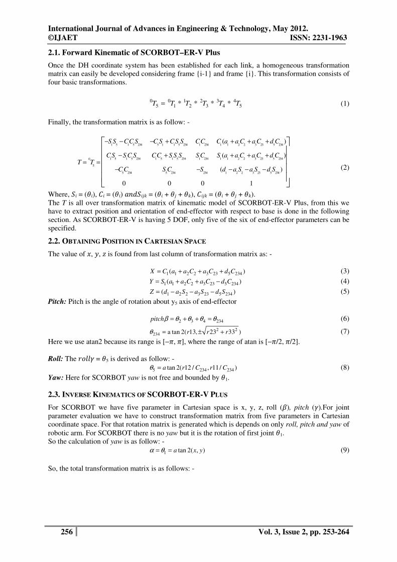
2.1. Forward Kinematic of SCORBOT–ER-V Plus
Once the DH coordinate system has been established for each link, a homogeneous transformation
matrix can easily be developed considering frame {i-1} and frame {i}. This transformation consists of
four basic transformations.
0 0 1 2 3 4
5 1 2 3 4 5* * * *T T T T T T=
(1)
Finally, the transformation matrix is as follow: -
1 5 1 5 234 5 1 1 5 234 1 234 1 1 2 2 3 23 5 234
1 5 1 5 234 1 5 1 5 234 1 234 1 1 2 2 3 23 5 2340
5
5 234 5 234 234 1 2 2 3 23 5 234
( )
( )
( )
0 0 0 1
S S CC S C S CS S CC C a a C a C d C
CS S C S CC S S S S C S a a C a C d CT T
C C S C S d a S a S d S
− − − + + + +
− + + + += =
− − − − −
(2)
Where, �� = (��), �� = (��) � ����� = (�� + �� + ��), ���� = (�� + �� + ��).
The T is all over transformation matrix of kinematic model of SCORBOT-ER-V Plus, from this we
have to extract position and orientation of end-effector with respect to base is done in the following
section. As SCORBOT-ER-V is having 5 DOF, only five of the six of end-effector parameters can be
specified.
2.2. OBTAINING POSITION IN CARTESIAN SPACE
The value of �, �, � is found from last column of transformation matrix as: -
1 1 2 2 3 23 5 234( )X C a a C a C d C= + + +
(3)
1 1 2 2 3 23 5 234( )Y S a a C a C d C= + + − (4)
1 2 2 3 23 5 234( )Z d a S a S d S= − − −
(5)
Pitch: Pitch is the angle of rotation about y5 axis of end-effector
2 3 4 234pitchβ θ θ θ θ= + + = (6)
2 2234 a tan 2( 13, 23 33 )r r rθ = ± + (7)
Here we use atan2 because its range is [−�, �], where the range of atan is [−�/2, �/2].
Roll: The ���� = �5 is derived as follow: -
5 234 234tan 2( 12 / , 11/ )a r C r Cθ = (8)
Yaw: Here for SCORBOT yaw is not free and bounded by �1.
2.3. INVERSE KINEMATICS OF SCORBOT-ER-V PLUS
For SCORBOT we have five parameter in Cartesian space is x, y, z, roll (�), pitch (�).For joint
parameter evaluation we have to construct transformation matrix from five parameters in Cartesian
coordinate space. For that rotation matrix is generated which is depends on only roll, pitch and yaw of
robotic arm. For SCORBOT there is no yaw but it is the rotation of first joint �1.
So the calculation of yaw is as follow: -
1 tan 2( , )a x yα θ= = (9)
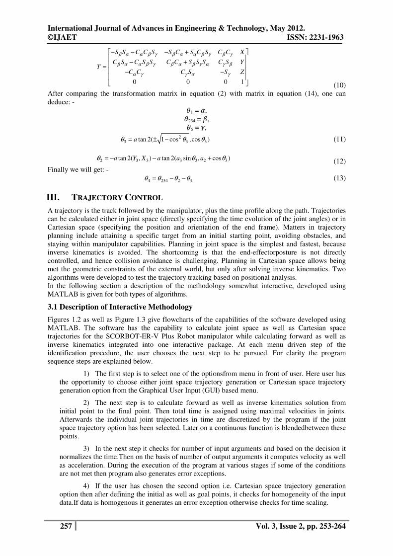
So, the total transformation matrix is as follows: -
International Journal of Advances in Engineering & Technology, May 2012.
©IJAET ISSN: 2231-1963
257 Vol. 3, Issue 2, pp. 253-264
0 0 0 1
S S C C S S C S C S C C X
C S C S S C C S S S C S YT
C C C S S Z
β α α β γ β α α β γ β γ
β α α β γ β α β γ α γ β
α γ γ α γ
− − − +
− + = − − (10)
After comparing the transformation matrix in equation (2) with matrix in equation (14), one can
deduce: -
�1 = �,
�234 = �,
�5 = �,
23 3 3tan 2( 1 cos ,cos )aθ θ θ= ± − (11)
2 3 3 3 3 2 3tan 2( , ) tan 2( sin , cos )a Y X a a aθ θ θ= − − + (12)
Finally we will get: -
4 234 2 3θ θ θ θ= − − (13)
III. TRAJECTORY CONTROL
A trajectory is the track followed by the manipulator, plus the time profile along the path. Trajectories
can be calculated either in joint space (directly specifying the time evolution of the joint angles) or in
Cartesian space (specifying the position and orientation of the end frame). Matters in trajectory
planning include attaining a specific target from an initial starting point, avoiding obstacles, and
staying within manipulator capabilities. Planning in joint space is the simplest and fastest, because
inverse kinematics is avoided. The shortcoming is that the end-effectorposture is not directly
controlled, and hence collision avoidance is challenging. Planning in Cartesian space allows being
met the geometric constraints of the external world, but only after solving inverse kinematics. Two
algorithms were developed to test the trajectory tracking based on positional analysis.
In the following section a description of the methodology somewhat interactive, developed using
MATLAB is given for both types of algorithms.
3.1 Description of Interactive Methodology
Figures 1.2 as well as Figure 1.3 give flowcharts of the capabilities of the software developed using
MATLAB. The software has the capability to calculate joint space as well as Cartesian space
trajectories for the SCORBOT-ER-V Plus Robot manipulator while calculating forward as well as
inverse kinematics integrated into one interactive package. At each menu driven step of the
identification procedure, the user chooses the next step to be pursued. For clarity the program
sequence steps are explained below.
1) The first step is to select one of the optionsfrom menu in front of user. Here user has
the opportunity to choose either joint space trajectory generation or Cartesian space trajectory
generation option from the Graphical User Input (GUI) based menu.
2) The next step is to calculate forward as well as inverse kinematics solution from
initial point to the final point. Then total time is assigned using maximal velocities in joints.
Afterwards the individual joint trajectories in time are discretized by the program if the joint
space trajectory option has been selected. Later on a continuous function is blendedbetween these
points.
3) In the next step it checks for number of input arguments and based on the decision it
normalizes the time.Then on the basis of number of output arguments it computes velocity as well
as acceleration. During the execution of the program at various stages if some of the conditions
are not met then program also generates error exceptions.
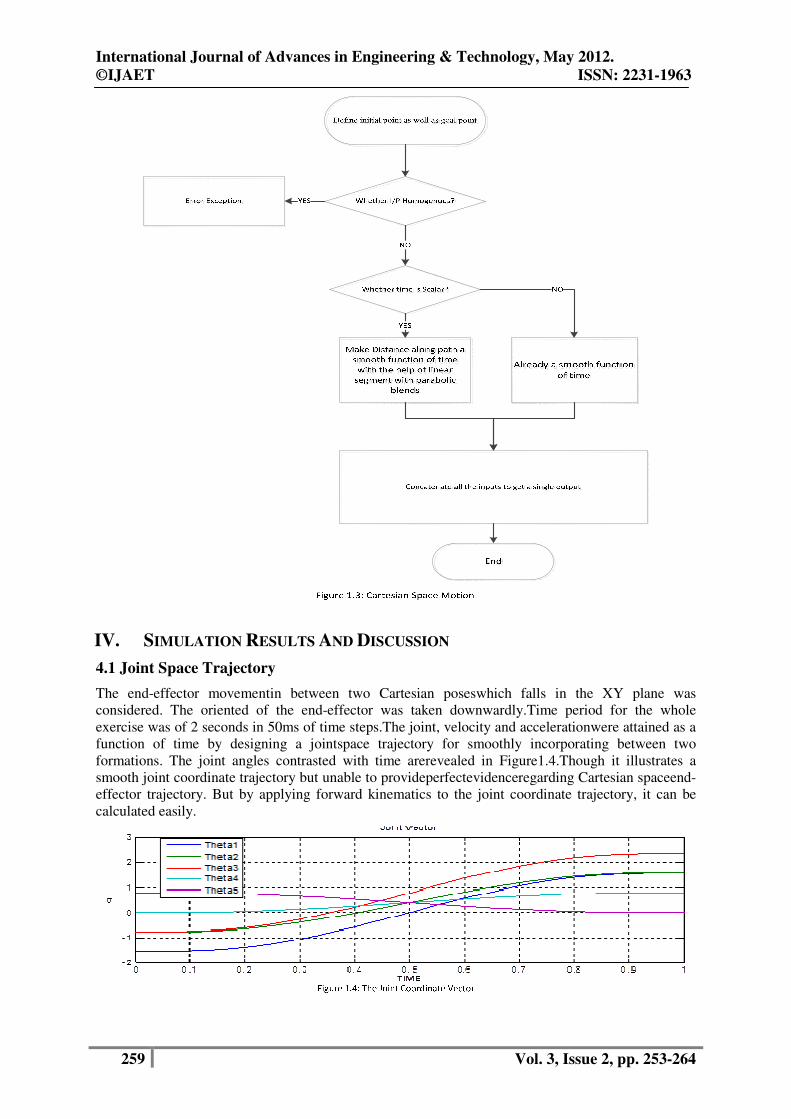
4) If the user has chosen the second option i.e. Cartesian space trajectory generation
option then after defining the initial as well as goal points, it checks for homogeneity of the input
data.If data is homogenous it generates an error exception otherwise checks for time scaling.
International Journal of Advances in Engineering & Technology, May 2012.
©IJAET ISSN: 2231-1963
258 Vol. 3, Issue 2, pp. 253-264
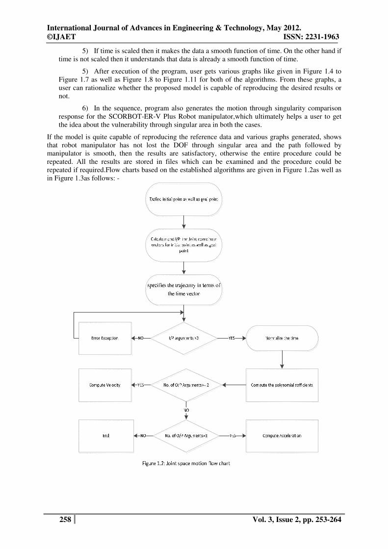
5) If time is scaled then it makes the data a smooth function of time. On the other hand if
time is not scaled then it understands that data is already a smooth function of time.
5) After execution of the program, user gets various graphs like given in Figure 1.4 to
Figure 1.7 as well as Figure 1.8 to Figure 1.11 for both of the algorithms. From these graphs, a
user can rationalize whether the proposed model is capable of reproducing the desired results or
not.
6) In the sequence, program also generates the motion through singularity comparison
response for the SCORBOT-ER-V Plus Robot manipulator,which ultimately helps a user to get
the idea about the vulnerability through singular area in both the cases.
If the model is quite capable of reproducing the reference data and various graphs generated, shows
that robot manipulator has not lost the DOF through singular area and the path followed by
manipulator is smooth, then the results are satisfactory, otherwise the entire procedure could be
repeated. All the results are stored in files which can be examined and the procedure could be
repeated if required.Flow charts based on the established algorithms are given in Figure 1.2as well as
in Figure 1.3as follows: -
International Journal of Advances in Engineering & Technology, May 2012.
©IJAET ISSN: 2231-1963
259 Vol. 3, Issue 2, pp. 253-264
IV. SIMULATION RESULTS AND DISCUSSION
4.1 Joint Space Trajectory
The end-effector movementin between two Cartesian poseswhich falls in the XY plane was
considered. The oriented of the end-effector was taken downwardly.Time period for the whole
exercise was of 2 seconds in 50ms of time steps.The joint, velocity and accelerationwere attained as a
function of time by designing a jointspace trajectory for smoothly incorporating between two
formations. The joint angles contrasted with time arerevealed in Figure1.4.Though it illustrates a
smooth joint coordinate trajectory but unable to provideperfectevidenceregarding Cartesian spaceend-
effector trajectory. But by applying forward kinematics to the joint coordinate trajectory, it can be
calculated easily.
International Journal of Advances in Engineering & Technology, May 2012.
©IJAET ISSN: 2231-1963
260 Vol. 3, Issue 2, pp. 253-264
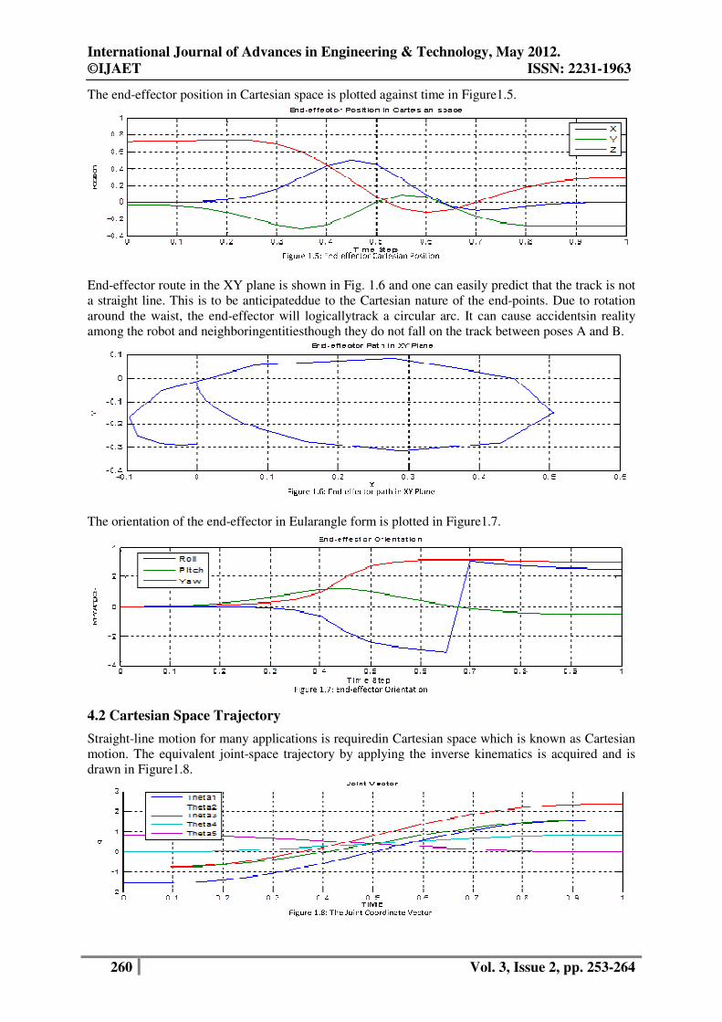
The end-effector position in Cartesian space is plotted against time in Figure1.5.
End-effector route in the XY plane is shown in Fig. 1.6 and one can easily predict that the track is not
a straight line. This is to be anticipateddue to the Cartesian nature of the end-points. Due to rotation
around the waist, the end-effector will logicallytrack a circular arc. It can cause accidentsin reality
among the robot and neighboringentitiesthough they do not fall on the track between poses A and B.
The orientation of the end-effector in Eularangle form is plotted in Figure1.7.
4.2 Cartesian Space Trajectory
Straight-line motion for many applications is requiredin Cartesian space which is known as Cartesian
motion. The equivalent joint-space trajectory by applying the inverse kinematics is acquired and is
drawn in Figure1.8.
International Journal of Advances in Engineering & Technology, May 2012.
©IJAET ISSN: 2231-1963
261 Vol. 3, Issue 2, pp. 253-264
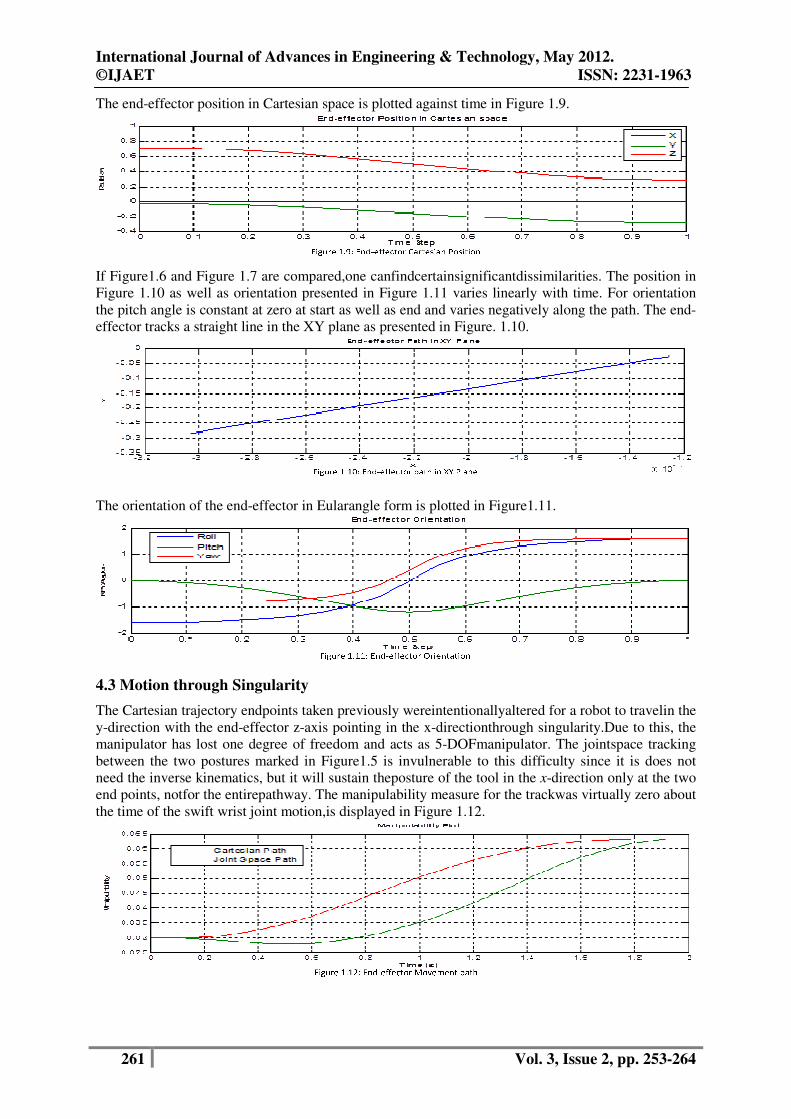
The end-effector position in Cartesian space is plotted against time in Figure 1.9.
If Figure1.6 and Figure 1.7 are compared,one canfindcertainsignificantdissimilarities. The position in
Figure 1.10 as well as orientation presented in Figure 1.11 varies linearly with time. For orientation
the pitch angle is constant at zero at start as well as end and varies negatively along the path. The end-
effector tracks a straight line in the XY plane as presented in Figure. 1.10.
The orientation of the end-effector in Eularangle form is plotted in Figure1.11.
4.3 Motion through Singularity
The Cartesian trajectory endpoints taken previously wereintentionallyaltered for a robot to travelin the
y-direction with the end-effector z-axis pointing in the x-directionthrough singularity.Due to this, the
manipulator has lost one degree of freedom and acts as 5-DOFmanipulator. The jointspace tracking
between the two postures marked in Figure1.5 is invulnerable to this difficulty since it is does not
need the inverse kinematics, but it will sustain theposture of the tool in the x-direction only at the two
end points, notfor the entirepathway. The manipulability measure for the trackwas virtually zero about
the time of the swift wrist joint motion,is displayed in Figure 1.12.
International Journal of Advances in Engineering & Technology, May 2012.
©IJAET ISSN: 2231-1963
262 Vol. 3, Issue 2, pp. 253-264
V. CONCLUSION
Two methodologiesprincipallycentered on joint space as well as Cartesian space trackingfortracking
the end-effector effortlessly between dissimilarpostures were presented. The precision of the output of
the projected algorithms for effective positional tracking control of industrial robot can be
experiencedfrom the simulation results. Joint space trajectorymay be challenging for some
applicationsdue to not result in Cartesian space straight line trajectory. Due tosingularities in the
workspace, though straight line Cartesian space trajectory can be established but may lead to very
high joint rates.Collision avoidance is difficult due to non-operability of end-effector in case of joint
space trajectory tracking. On the other to realize thegeometric constraints of the external world in
Cartesian space one has to solve the inverse kinematics. The methodology presented here can be
extended to be used for trajectory planning and quite a few tracking applications based on positional
analysis with real world disturbances. The present work did not make use of dynamics of robot
manipulator, so it could be extended for the same also.
ACKNOWLEDGEMENTS
As it is the case in almost all parts of human endeavour so also the development in the field of
robotics has been carried on by engineers and scientists all over the world. It can be regarded as a duty
to express the appreciation for such relevant, interesting and outstanding work to which ample
reference is made in this paper.
REFERENCES
[1] Featherstone R, "Position and velocity transformation between robot end-effector coordinate and joint
angle," International Journal of Robotics, vol. 2, no. 2, pp. 35-45, 1983.
[2] Lee G. C. S., "Robot arm kinematics, dynamics and control," IEEE, vol. 15, no. 12, pp. 62-79, 1982.
[3] Duffy J., Analysis of Mechanism and Robot Manipulators. New York, USA: Wiley, 1980.
[4] D. Manocha and JF Canny, "Efficient inverse kinematics for general 6r manipulators," IEEE Transaction
on Robotics Automation, IEEE, vol. 10, no. 5, pp. 648-657, 1994.
[5] RP Paul, B. Shimano, and GE Mayer, "Kinematic control equations for simple manipulators," IEEE
Transaction on System, Man and Cybernetics, IEEE, vol. SMC-11, no. 6, pp. 66-72, 1982.
[6] JU Korein and NI Balder, "Techniques for generating the goal-directed motion of articulated structures,"
IEEE Computer Graphics and Application, IEEE, vol. 2, no. 9, pp. 71-81, 1982.
[7] D. M. A. Lee, R. O. Buchal, W. H. Elmaraghy H. Jack, "Neural Networks and The Inverse Kinematics
Problem," Journal of Intelligent Manufacturing, vol. 4, pp. 43-66, 1993.
[8] Aluizio F. R. Arahjo and Hclio D'arbo Jr., "A Partially Recurrent Neural Network To Perform Trajectory
Planning, Inverse Kinematics and Inverse Dynamics," Systems, Man and Cybernetics, IEEE, vol. 2, pp.
1784 - 1789, 1998.
[9] David W. Howard and Ali Zilouchian, "Application of Fuzzy Logic for The Solution Of Inverse
Kinematics And Hierarchical Controls Of Robotic Manipulators," Journal of Intelligent and Robotic
Systems, Kluwer Academic Publishers, vol. 23, pp. 217–247, 1998.
[10] Eimei Oyama, Nak Young Chong, Arvin Agah, Taro Maeda, and Susumu Tachi, "Inverse Kinematics
Learning By Modular Architecture Neural Networks With Performance Prediction Networks,"
International Conference On Robotics & Automation, IEEE, pp. 1006-1012, 2001.
[11] Rasit Koker, Cemil Oz, Tarik Cakar, and Huseyin Ekiz, "A Study Of Neural Network Based Inverse
Kinematics Solution For A Three-Joint Robot," Robotics and Autonomous Systems, Elsvier, vol. 49, pp.
227–234, 2004.
[12] Z. Bingul, H.M. Ertunc, and C. Oysu, "Comparison Of Inverse Kinematics Solutions Using Neural
Network For 6r Robot Manipulator With Offset," Computational Intelligence Methods And Applications,
IEEE, pp. 1-5, 2005.
[13] D.T. Pham, M. Castellani, and A. A. Fahmy, "Learning The Inverse Kinematics Of A Robot Manipulator
Using The Bees Algorithm," International Conference On Industrial Informatics, IEEE, pp. 493-498, 2008.
[14] Ren e V. Mayorga and Pronnapa Sanongboon, "Inverse kinematics and geometrically bounded singularities
prevention of redundant manipulators: An Artificial Neural Network approach," Elsevier, Robotics and
Autonomous Systems, vol. 53, pp. 164–176, 2005.
International Journal of Advances in Engineering & Technology, May 2012.
©IJAET ISSN: 2231-1963
263 Vol. 3, Issue 2, pp. 253-264
[15] Rasit Koker, "Reliability-based approach to the inverse kinematics solution of robots using Elman’s
networks," Elsevier, Engineering Applications of Artificial Intelligence, vol. 18, pp. 685–693, 2005.
[16] Ali T. Hasan, A.M.S. Hamouda, N. Ismail, and H.M.A.A. Al-Assadi, "An adaptive-learning algorithm to
solve the inverse kinematics problem of a 6 D.O.F serial robot manipulator," Elsevier, Advances in
Engineering Software, vol. 37, pp. 432–438, 2006.
[17] Himanshu Chaudhary and Rajendra Prasad, "Intelligent Inverse Kinematic Control of SCORBOT-ER-V
Plus Robot Manipulator," International Journal of Advances in Engineering & Technology, vol. 1, no. 5,
pp. 158-169, November 2011.
[18] Kwang Sik Eoma, Il Hong Suha, and Wan Kyun Chungb, "Disturbance observer based path tracking
control of robot manipulator considering," PERGAMON, MECHATRONICS, vol. 11 , pp. 325-343, 2000.
[19] Zaer S. Abo-Hammoura, Nasir M. Mirza, Sikander M. Mirza, and Muhammad Arif, "Cartesian path
generation of robot manipulators using continuous genetic algorithms," Elsevier, Robotics and Autonomous
Systems, vol. 41, pp. 179–223, 2002.
[20] Xuan F. Zha, "Optimal pose trajectory planning for robot manipulators," PERGAMON, Mechanism and
Machine Theory, vol. 37, pp. 1063–1086, 2002.
[21] T. Chettibi, H.E. Lehtihet, M. Haddada, and S. Hanchi b, "Minimum cost trajectory planning for industrial
robots," Elsevier, European Journal of Mechanics A/Solids, vol. 23, pp. 703–715, 2004.
[22] Marcos de Sales Guerra Tsuzuki, Thiago de Castro Martins, and Fdbio Kawaoka Takase, "ROBOT PATH
PLANNING USING SIMULATED ANNEALING," Elsevier, Information Control Problems in
Manufacturing - MCOM, pp. 173-178, 2006.
[23] A. Gasparetto and V. Zanotto, "A new method for smooth trajectory planning of robot manipulators,"
Elsevier, Mechanism and Machine Theory, vol. 42, pp. 455–471, 2007.
[24] Zhenwang Yao and Kamal Gupta, "Path planning with general end-effector constraints," Elsevier, Robotics
and Autonomous Systems, vol. 55, pp. 316–327, 2007.
[25] M. Boryga and A. Grabos, "Planning of manipulator motion trajectory with higher-degree polynomials
use," Elsevier, Mechanism and Machine Theory, vol. 44, pp. 1400–1419, 2009.
[26] Wanghui Bu, Zhenyu Liu, Jianrong Tan, and Shuming Gao, "Detachment avoidance of joint elements of a
robotic manipulator with clearances based on trajectory planning," Elsevier, Mechanism and Machine
Theory, vol. 45, pp. 925–940, 2010.
[27] A. Gasparetto and V. Zanotto, "Optimal trajectory planning for industrial robots," Elsevier, Advances in
Engineering Software, vol. 41, pp. 548–556, 2010.
[28] Claire Dumas, Stephane Caro, Sebastien Garnier, and Benoıt Furet, "Joint stiffness identification of six-
revolute industrial serial robots," Elsevier, Robotics and Computer-Integrated Manufacturing, vol. 27, pp.
881–888, 2011.
[29] Eski, Ikbal, et al., "Fault detection on robot manipulators using artificial neural networks." Robotics and
Computer-Integrated Manufacturing, s.l. : Elsevier , 2011, Vol. 27, pp. 115–123.
[30] Guernanea, R. and Achourb, N., "Generating optimized paths for motion planning." Robotics and
Autonomous Systems, s.l. : Elsevier, 2011, Vol. 59, pp. 789–800.
[31] Yahya, Samer, Moghavvemi, M. and Mohamed, Haider A. F., "Geometrical approach of planar hyper-
redundant manipulators:Inverse kinematics, path planning and workspace." Simulation Modelling Practice
and Theory, s.l. : Elsevier, 2011, Vol. 19, pp. 406–422.
[32] Duguleana, Mihai, et al., "Obstacle avoidance of redundant manipulators using neural networks based
reinforcement learning." Robotics and Computer-Integrated Manufacturing, s.l. : Elsevier, 2012, Vol. 28,
pp. 132–146.
Authors
Himanshu Chaudhary received his B.E. in Electronics and Telecommunication from Amravati
University, Amravati, India in 1996, M.E. in Automatic Controls and Robotics from M.S.
University, Baroda, Gujarat, India in 2000. Presently he is a research scholar in Electrical
Engineering Department, IIT Roorkee, India. His area of interest includes industrial robotics,
computer networks and embedded systems.
International Journal of Advances in Engineering & Technology, May 2012.
©IJAET
264
Rajendra Prasad received B.Sc. (Hons.) degree from Meerut University, India in 1973. He
received B.E.,M.E. and Ph.D. degree in Electrical Engineering from the University of Roorkee,
India in 1977, 1979 and 1990 respectively.
Pradesh Electricity Board (MPEB) from 1979
Department of Electrical Engineering, Indian Institute of Technology Roorkee, Roorkee
(India).He has more than 32 years of experience of teaching as well as industry.
published 176 papers in various Journals/conferences and received eight awards on his publications in various
National/International Journals/Conferences Proceeding papers. He has gui
PhD’s are under progress. His research interests include Control, Optimization, System Engineering and Model
Order Reduction of Large Scale Systems
N. Sukavanum was born in India in 1957. He re
Madras, India in 1977 and M.Sc. (Maths) from the same university in 1979 and Ph.D. (Maths)
from IISC Bangalore, India in 1985 respectively. He has served as a Scientist
and Technological Laboratory, DRDO, Vizag
also worked as a Lecturer at Birla Institute of Technology and Science, Pilani, Rajasthan from
1990 to 1996. He worked as an Assistant Professor in Mathematics Department at Indian Inst
of Technology, Roorkee during May 1996
Department of Mathematics, Indian Institute of Technology Roorkee, Roorkee (India). He has published
papers in various Journals/conferences. He has g
His research interests include Nonlinear Analysis, Control theory and Robotics and control.
International Journal of Advances in Engineering & Technology, May 2012.
Vol. 3, Issue 2, pp.
received B.Sc. (Hons.) degree from Meerut University, India in 1973. He
received B.E.,M.E. and Ph.D. degree in Electrical Engineering from the University of Roorkee,
India in 1977, 1979 and 1990 respectively. . He also served as an Assistant Engineer in Ma
Pradesh Electricity Board (MPEB) from 1979- 1983. Currently, he is a Professor in the
Department of Electrical Engineering, Indian Institute of Technology Roorkee, Roorkee
more than 32 years of experience of teaching as well as industry. He has
published 176 papers in various Journals/conferences and received eight awards on his publications in various
National/International Journals/Conferences Proceeding papers. He has guided Seven PhD
are under progress. His research interests include Control, Optimization, System Engineering and Model
Order Reduction of Large Scale Systems and industrial robotics.
was born in India in 1957. He received B.Sc. (Maths) degree from University of
M.Sc. (Maths) from the same university in 1979 and Ph.D. (Maths)
, India in 1985 respectively. He has served as a Scientist-B in Naval Science
oratory, DRDO, Vizag, and as a Research Scientist in I I T, Bombay
also worked as a Lecturer at Birla Institute of Technology and Science, Pilani, Rajasthan from
1990 to 1996. He worked as an Assistant Professor in Mathematics Department at Indian Inst
of Technology, Roorkee during May 1996–April 2004. Presently, he is an Associate Professor in the
Department of Mathematics, Indian Institute of Technology Roorkee, Roorkee (India). He has published
papers in various Journals/conferences. He has guided nine PhD’s, and presently six Ph. D’s are under progress.
His research interests include Nonlinear Analysis, Control theory and Robotics and control.
International Journal of Advances in Engineering & Technology, May 2012.
ISSN: 2231-1963
Vol. 3, Issue 2, pp. 253-264
received B.Sc. (Hons.) degree from Meerut University, India in 1973. He
received B.E.,M.E. and Ph.D. degree in Electrical Engineering from the University of Roorkee,
served as an Assistant Engineer in Madhya
, he is a Professor in the
Department of Electrical Engineering, Indian Institute of Technology Roorkee, Roorkee
He has
published 176 papers in various Journals/conferences and received eight awards on his publications in various
PhD’s, and presently six
are under progress. His research interests include Control, Optimization, System Engineering and Model
ceived B.Sc. (Maths) degree from University of
M.Sc. (Maths) from the same university in 1979 and Ph.D. (Maths)
B in Naval Science
as a Research Scientist in I I T, Bombay. He
also worked as a Lecturer at Birla Institute of Technology and Science, Pilani, Rajasthan from
1990 to 1996. He worked as an Assistant Professor in Mathematics Department at Indian Institute
April 2004. Presently, he is an Associate Professor in the
Department of Mathematics, Indian Institute of Technology Roorkee, Roorkee (India). He has published 60
Ph. D’s are under progress.
His research interests include Nonlinear Analysis, Control theory and Robotics and control.